EP3748829A1 - Topology unit parallel-connection protection method, device and system - Google Patents
Topology unit parallel-connection protection method, device and system Download PDFInfo
- Publication number
- EP3748829A1 EP3748829A1 EP19897575.7A EP19897575A EP3748829A1 EP 3748829 A1 EP3748829 A1 EP 3748829A1 EP 19897575 A EP19897575 A EP 19897575A EP 3748829 A1 EP3748829 A1 EP 3748829A1
- Authority
- EP
- European Patent Office
- Prior art keywords
- signal
- power module
- controller
- sub
- line
- Prior art date
- Legal status (The legal status is an assumption and is not a legal conclusion. Google has not performed a legal analysis and makes no representation as to the accuracy of the status listed.)
- Pending
Links
Images





Classifications
-
- H—ELECTRICITY
- H02—GENERATION; CONVERSION OR DISTRIBUTION OF ELECTRIC POWER
- H02M—APPARATUS FOR CONVERSION BETWEEN AC AND AC, BETWEEN AC AND DC, OR BETWEEN DC AND DC, AND FOR USE WITH MAINS OR SIMILAR POWER SUPPLY SYSTEMS; CONVERSION OF DC OR AC INPUT POWER INTO SURGE OUTPUT POWER; CONTROL OR REGULATION THEREOF
- H02M1/00—Details of apparatus for conversion
- H02M1/32—Means for protecting converters other than automatic disconnection
-
- H—ELECTRICITY
- H02—GENERATION; CONVERSION OR DISTRIBUTION OF ELECTRIC POWER
- H02H—EMERGENCY PROTECTIVE CIRCUIT ARRANGEMENTS
- H02H7/00—Emergency protective circuit arrangements specially adapted for specific types of electric machines or apparatus or for sectionalised protection of cable or line systems, and effecting automatic switching in the event of an undesired change from normal working conditions
- H02H7/26—Sectionalised protection of cable or line systems, e.g. for disconnecting a section on which a short-circuit, earth fault, or arc discharge has occured
- H02H7/267—Sectionalised protection of cable or line systems, e.g. for disconnecting a section on which a short-circuit, earth fault, or arc discharge has occured for parallel lines and wires
-
- H—ELECTRICITY
- H02—GENERATION; CONVERSION OR DISTRIBUTION OF ELECTRIC POWER
- H02H—EMERGENCY PROTECTIVE CIRCUIT ARRANGEMENTS
- H02H7/00—Emergency protective circuit arrangements specially adapted for specific types of electric machines or apparatus or for sectionalised protection of cable or line systems, and effecting automatic switching in the event of an undesired change from normal working conditions
- H02H7/10—Emergency protective circuit arrangements specially adapted for specific types of electric machines or apparatus or for sectionalised protection of cable or line systems, and effecting automatic switching in the event of an undesired change from normal working conditions for converters; for rectifiers
- H02H7/12—Emergency protective circuit arrangements specially adapted for specific types of electric machines or apparatus or for sectionalised protection of cable or line systems, and effecting automatic switching in the event of an undesired change from normal working conditions for converters; for rectifiers for static converters or rectifiers
- H02H7/122—Emergency protective circuit arrangements specially adapted for specific types of electric machines or apparatus or for sectionalised protection of cable or line systems, and effecting automatic switching in the event of an undesired change from normal working conditions for converters; for rectifiers for static converters or rectifiers for inverters, i.e. DC/AC converters
- H02H7/1225—Emergency protective circuit arrangements specially adapted for specific types of electric machines or apparatus or for sectionalised protection of cable or line systems, and effecting automatic switching in the event of an undesired change from normal working conditions for converters; for rectifiers for static converters or rectifiers for inverters, i.e. DC/AC converters responsive to internal faults, e.g. shoot-through
Definitions
- the present disclosure relates to the technical field of new energy, and in particular to a method, a device, and a system for protecting parallel-connected topology units.
- topology units are connected in parallel in a power electronic converter system to achieve rapid expansion of capacity.
- input terminals of two topology units are connected in parallel, and output terminals of the two topology units are also connected in parallel.
- fault protection may be performed by connecting a fuse in series in the topology unit.
- a communication line may be established between topology units. Fault information is transmitted via the communication line when fault occurs in one topology unit, thereby avoiding damaging the other topology unit.
- the technical problem that is urgently to be solved by those skilled in the art is how to provide a method and a system for protecting parallel-connected topology units for rapidly performing fault protection without increasing the cost of a converter system.
- a method and a system for protecting parallel-connected topology units are provided according to the embodiments of the present disclosure for rapidly performing fault protection without increasing the cost of a converter system.
- a method for protecting parallel-connected topology units, applied to a system for protecting parallel-connected topology units is provided.
- the system for protecting parallel-connected topology units includes topology units connected in parallel, each of the topology units includes a controller and a power module, the controller performs signal transmission with at least one of other controllers via a signal synchronization line, and the method for protecting parallel-connected topology units includes:
- the method for protecting parallel-connected topology units further includes, if the target signal is the carrier synchronization signal, determining a fault state of the power module. If the fault state is a normal state, the target signal is transmitted to the other controllers, the current power module is controlled to perform carrier synchronization and is controlled to be in the working mode. If the fault state is a faulty state, the power module fault signal is sent to the other controllers and the current power module is controlled to be in the shutdown mode.
- the controller is a single controller, the single controller is connected to the power module via a state acquisition signal line, the single controller acquires the power module fault signal sent by the power module and sends the power module fault signal via the signal synchronization line.
- the obtaining the target signal transmitted via the signal synchronization line includes:
- the controller includes a first sub-controller and a second sub-controller, the first sub-controller is connected to the second sub-controller via a feedback signal line, the second sub-controller performs signal transmission with at least one of other second sub-controllers via the signal synchronization line, and the second sub-controller is connected to the power module via a state acquisition signal line.
- the second sub-controller obtains the target signal transmitted via the signal synchronization line.
- the second sub-controller acquires a fault state of the power module via the state acquisition signal line. If the fault state is a normal state, the second sub-controller transmits the target signal to the other second sub-controllers via the signal synchronization line and transmits the target signal to the first sub-controller via the feedback signal line, and the first sub-controller performs carrier synchronization and controls the current power module to be in the working mode.
- the second sub-controller transmits the power module fault signal to the other second sub-controllers via the signal synchronization line and transmits the power module fault signal to the first sub-controller via the feedback signal line, and the first sub-controller controls the current power module to be in the shutdown mode.
- the second sub-controller sends the target signal to the other second sub-controllers via the signal synchronization line and transmits the target signal to the first sub-controller via the feedback signal line, and the first sub-controller controls the current power module to be in the shutdown mode.
- the first sub-controller is a DSP and the second sub-controller is a CPLD.
- a device for protecting parallel-connected topology units applied to a system for protecting parallel-connected topology units is provided.
- the system for protecting parallel-connected topology units includes topology units connected in parallel, each of the topology units includes a controller and a power module, the controller performs signal transmission with at least one of other controllers via a signal synchronization line, and the device for protecting parallel-connected topology units includes an obtaining module, a sending module, and a control module.
- the obtaining module is configured to obtain a target signal transmitted via the signal synchronization line,
- the sending module is configured to send the target signal to the other controllers based on a type of the target signal.
- the control module is configured to control a current power module to perform carrier synchronization and control the current power module to be in a working mode if the target signal is a carrier synchronization signal, and control the current power module to be in a shutdown mode if the target signal is a power module fault signal.
- the device for protecting parallel-connected topology units further includes a determining module.
- the determining module is configured to, if the target signal is the carrier synchronization signal, determine a fault state of the power module.
- the determining module is configured to transmit the target signal to the other controllers, control the current power module to perform carrier synchronization and control the current power module to be in the working mode if the fault state is a normal state, and send the power module fault signal to the other controllers and control the current power module to be in the shutdown mode if the fault state is a faulty state.
- the controller is a single controller, the single controller is connected to the power module via a state acquisition signal line, the single controller acquires the power module fault signal sent by the power module and sends the power module fault signal via the signal synchronization line.
- the obtaining module includes: a first acquiring unit and a determining unit.
- the first acquiring unit is configured to acquire, by controller, the carrier synchronization signal or the power module fault signal transmitted via the signal synchronization line, and
- the determining unit is configured to determine the power module fault signal or the carrier synchronization signal as the target signal.
- a system for protecting parallel-connected topology units including topology units connected in parallel, each of the topology units includes a controller and a power module, the controller performs signal transmission with at least one of other controllers via a signal synchronization line.
- the controller obtains a target signal transmitted via the signal synchronization line.
- the controller sends the target signal to the other controllers based on a type of the target signal.
- the controller controls a current power module to perform carrier synchronization and controls the current power module to be in a working mode if the target signal is a carrier synchronization signal, and controls the current power module to be in a shutdown mode if the target signal is a power module fault signal.
- the controller is a single controller, the single controller is connected to the power module via a state acquisition signal line, the single controller acquires the power module fault signal sent by the power module and sends the power module fault signal via the signal synchronization line.
- the controller obtaining the target signal transmitted via the signal synchronization line includes the single controller being configured to: acquire the carrier synchronization signal or the power module fault signal transmitted via the signal synchronization line, and determine the power module fault signal or the carrier synchronization signal as the target signal.
- the controller includes a first sub-controller and a second sub-controller, the first sub-controller is connected to the second sub-controller via a feedback signal line, the second sub-controller performs signal transmission with at least one of other second sub-controllers via the signal synchronization line, and the second sub-controller is connected to the power module via a state acquisition signal line.
- the controller obtaining the target signal transmitted via the signal synchronization line includes:
- the second sub-controller acquiring a fault state of the power module via the state acquisition signal line. If the fault state is a normal state, the second sub-controller transmits the target signal to the other second sub-controllers via the signal synchronization line and transmits the target signal to the first sub-controller via the feedback signal line, and the first sub-controller performs carrier synchronization and controls the current power module to be in the working mode.
- the second sub-controller transmits the power module fault signal to the other second sub-controllers via the signal synchronization line and transmits the power module fault signal to the first sub-controller via the feedback signal line, and the first sub-controller controls the current power module to be in the shutdown mode.
- the second sub-controller sends the target signal to the other second sub-controllers via the signal synchronization line and transmits the target signal to the first sub-controller via the feedback signal line, and the first sub-controller controls the current power module to be in the shutdown mode.
- the first sub-controller is a DSP and the second sub-controller is a CPLD.
- the method for protecting parallel-connected topology units applied to a system for protecting parallel-connected topology units, is provided according to the embodiments of the present disclosure.
- the system for protecting parallel-connected topology units includes topology units connected in parallel.
- Each of the topology units includes a controller and a power module.
- the controller performs signal transmission with at least one of other controllers via a signal synchronization line.
- the target signal transmitted via the signal synchronization line is first obtained, and the target signal is sent to the other controllers based on a type of the target signal. If the target signal is the carrier synchronization signal, the current power module is controlled to perform carrier synchronization and is controlled to be in a working mode.
- the target signal is the power module fault signal
- the current power module is controlled to be in the shutdown mode.
- the signal synchronization lines between the topology units connected in parallel are shared in a time-sharing manner.
- the carrier synchronization signal is transmitted via the signal synchronization line if the power module works normally, and the power module fault signal is transmitted via the signal synchronization line if the power module is faulty.
- Each of the topology units monitors the transmitted target signal in a real time manner to achieve fast synchronous protection.
- FIG. 5 is a schematic structural diagram of a system for protecting parallel-connected topology units according to an embodiment of the present disclosure.
- the system for protecting parallel-connected topology units includes multiple topology units connected in parallel.
- Signal synchronization lines are arranged between the multiple topology units for transmitting carrier synchronization signals, thereby implementing PWM carrier synchronization and suppressing circulating currents.
- the topology unit may be an inverter unit, a rectifier, or a DC/DC converter.
- an inverter unit is used as an example of the topology unit for describing the principle of a method for protecting parallel-connected topology units according to the present disclosure.
- the signal synchronization lines may be implemented by optical fibers or wires for transmitting an optical signal or an electrical signal at high transmission rates.
- the topology unit includes a controller and a power module.
- the controller is a single controller.
- the single controller is connected to the power module via a state acquisition signal line to acquire a power module fault signal sent by the power module and sends the power module fault signal via the signal synchronization line.
- the single controller may be implemented as any CPU.
- a method for protecting parallel-connected topology units is provided according to an embodiment. As shown in Figure 7 , the method includes following steps S1 to S4.
- step S1 a target signal transmitted via the signal synchronization line is obtained.
- step S2 the target signal is sent to the other controllers based on a type of the target signal.
- step S3 a current power module is controlled to perform carrier synchronization and controlled to be in a working mode if the target signal is a carrier synchronization signal.
- step S4 the current power module is controlled to be in a shutdown mode if the target signal is a power module fault signal.
- the controller CPU detects the type of the target signal transmitted via the signal synchronization line. If the target signal transmitted via the signal synchronization line is the carrier synchronization signal, the controller CPU performs PWM carrier synchronization and causes the current power module, that is, the power module connected to the controller CPU, to operate normally. If the target signal transmitted via the signal synchronization line is a power module fault signal, the controller CPU controls the current power module to be in a shutdown mode.
- the signal synchronization lines between the topology units connected in parallel are shared in a time-sharing manner.
- the carrier synchronization signal is transmitted through the signal synchronization line if the power module work normally, and the power module fault signal is transmitted through the signal synchronization line if the power module is faulty.
- Each of the topology units monitors the transmitted target signal in a real-time manner to achieve fast synchronous protection.
- the method according to the embodiment further includes following steps S31 to S33.
- step S31 a fault state of the power module is determined.
- step S32 if the fault state is a normal state, the target signal is transmitted to the other controllers, and the current power module is controlled to perform carrier synchronization and is controlled to be in the working mode.
- step S33 if the fault state is a faulty state, the power module fault signal is sent to the other controllers and the current power module is controlled to be in the shutdown mode.
- the controller CPU detects the type of the target signal transmitted via the signal synchronization line. If the target signal transmitted via the signal synchronization line is the carrier synchronization signal, the controller CPU detects whether the power module in the topology unit where the controller CPU is located is faulty via the state acquisition signal line. If all power modules operate normally, the controller CPU transmits the carrier synchronization signal to a next controller. The controller CPU performs PWM carrier synchronization and causes the power module to operate normally. If the power module is faulty, the controller CPU suspends sending the carrier synchronization signal and sends the power module fault signal via the signal synchronization line. If the target signal transmitted via the signal synchronization line is the power module fault signal, the power module fault signal is transparently transmitted to the next controller. The controller CPU receives the power module fault signal and the power module is shut down for protection.
- multiple controllers may form a ring signal network by using the signal synchronization lines.
- a controller CPU1 transmits the target signal to a controller CPU2 via a signal synchronization line
- the controller CPU2 transmits the target signal to a controller CPU3 via a signal synchronization line
- the controller CPU3 transmits the target signal to a controller CPU4 via a signal synchronization line
- the controller CPU4 transmits the target signal to the controller CPU1 via a signal synchronization line.
- multiple controllers may form a non-ring signal network via signal synchronization lines.
- a controller CPU1 transmits the target signal to a controller CPU2 via a signal synchronization line
- the controller CPU2 transmits the target signal to a controller CPU3 via a signal synchronization line
- the controller CPU3 transmits the target signal to a controller CPU4 via a signal synchronization line.
- the controller CPU4 does not transmit the target signal to the controller CPU1 via a signal synchronization line.
- an implementation for obtaining the target signal transmitted via the signal synchronization line is provided according to an embodiment of the present disclosure. As shown in Figure 10 , the implementation includes following step S101 and S102.
- step S101 the single controller acquires the carrier synchronization signal or the power module fault signal transmitted via the signal synchronization line.
- step S102 the power module fault signal or the carrier synchronization signal is determined as the target signal.
- the carrier synchronization signal is transmitted via the signal synchronization line.
- the target signal is the carrier synchronization signal, for performing PWM carrier synchronization. If the power module fault signal is transmitted via the signal synchronization line, the target signal is the power module fault signal, for notifying another controller to control the corresponding power module to be shut down.
- the controller may be a combination of a first sub-controller and a second sub-controller.
- the first sub-controller is defined as a main controller DSP
- the second sub-controller is defined as an auxiliary controller CPLD
- the first sub-controller is connected to the second sub-controller via a feedback signal line
- the second sub-controller is connected to at least one of other second sub-controllers via the signal synchronization line
- the second sub-controller is connected to the power module via the state acquisition signal line.
- FIG. 12 another implementation for obtaining the target signal transmitted via the signal synchronization line is provided according to an embodiment of the present disclosure.
- the implementation includes following step S121 and S123.
- step S121 the second sub-controller obtains the target signal transmitted via the signal synchronization line.
- step S122 if the target signal is the carrier synchronization signal, the second sub-controller acquires the fault state of the power module via the state acquisition signal line. If the fault state is the normal state, the second sub-controller transmits the target signal to the other second sub-controllers via the signal synchronization line and transmits the target signal to the first sub-controller via the feedback signal line, and the first sub-controller controls the current power module to perform carrier synchronization and controls the current power module to be in the working mode.
- the second sub-controller transmits the power module fault signal to the other second sub-controllers via the signal synchronization line and transmits the power module fault signal to the first sub-controller via the feedback signal line, and the first sub-controller controls the current power module to be in the shutdown mode.
- step S123 if the target signal is the power module fault signal, the second sub-controller sends the target signal to the other second sub-controllers via the signal synchronization line and transmits the target signal to the first sub-controller via the feedback signal line, and the first sub-controller controls the current power module to be in the shutdown mode.
- the second sub-controller may constantly acquire the fault state of the power module via the state acquisition signal line.
- the acquisition of the fault state is not limited to being performed in the case that the target signal is the carrier synchronization signal.
- a method for protecting parallel-connected topology units is provided according to another embodiment of the present disclosure. As shown in Figure 13 , the method includes following steps S131 to S139.
- an auxiliary controller CPLD detects the type of a signal transmitted via a ring network of signal synchronization lines.
- step S132 if the carrier synchronization signal is transmitted via the ring network, the auxiliary controller CPLD detects whether the power module in the unit where the auxiliary controller CPLD is located is faulty via the state acquisition signal line.
- step S133 if none of other power modules in the ring network and the power module in the unit where the auxiliary controller CPLD is located is faulty, the carrier synchronization signal is transmitted to a next unit in the ring network.
- step S134 the carrier synchronization signal is sent to the main controller DSP via the feedback signal line.
- step S135 the main controller DSP performs PWM carrier synchronization and the power module runs normally.
- step S136 if the power module fault signal is transmitted via the ring network, the power module fault signal is transparently transmitted to the next unit.
- step S137 if the power module in the unit where the auxiliary controller CPLD is located is faulty, the auxiliary controller CPLD suspends sending the carrier synchronization signal and sends the power module fault signal via the ring network.
- step S138 the power module fault signal is sent to the main controller DSP via the feedback signal line.
- step S139 the main controller DSP receives the power module fault signal, and the power module is shut down for protection.
- the power module fault signal is not detected by auxiliary controllers CPLD in all the units, and the carrier synchronization signal is transmitted via the ring network of signal synchronization lines.
- the auxiliary controllers CPLD feed the carrier synchronization signal back to respective main controllers DSP to ensure PWM carrier synchronization and normal operation of all the units.
- the auxiliary controller CPLD in the topology unit detects the power module fault signal, suspends sending the carrier synchronization signal and sends the power module fault signal, for example, high-frequency pulses, via the ring network of signal synchronization lines.
- auxiliary controllers CPLD in other units transparently transmit the power module fault signal to a next unit in the ring network, and feed the power module fault signal back to respective main controllers DSP.
- the signal transmitted via the signal synchronization line is changed from the carrier synchronization pulse to the power module fault signal, for example, as shown in Figure 16 , changed from low-frequency pulses to high-frequency pulses.
- the carrier synchronization signal is transmitted via the ring network of signal synchronization lines, for example, as shown in Figure 17 , the high-frequency pulses is replaced by low-frequency pulses.
- the carrier synchronization signal and the power module fault signal may be signals in other forms.
- the controller includes a first sub-controller and a second sub-controller, all the second sub-controllers may be connected into a ring network as shown in Figure 11 or may be connected into a non-ring network as shown in Figure 18 .
- a device for protecting parallel-connected topology units applied to a system for protecting parallel-connected topology units includes topology units connected in parallel, each of the topology units includes a controller and a power module, the controller performs signal transmission with at least one of other controllers via a signal synchronization line, and the device for protecting parallel-connected topology units includes: an obtaining module, a sending module, and a control module.
- the obtaining module is configured to obtain a target signal transmitted via the signal synchronization line.
- the sending module is configured to send the target signal to the other controllers based on a type of the target signal.
- the control module is configured to control a current power module to perform carrier synchronization and control the current power module to be in a working mode if the target signal is a carrier synchronization signal, and control the current power module to be in a shutdown mode if the target signal is a power module fault signal.
- the device for protecting parallel-connected topology units may further include a determining module.
- the determining module is configured to, if the target signal is the carrier synchronization signal, determine a fault state of the power module.
- the determining module is configured to, if the fault state is a normal state, transmit the target signal to the other controllers, control the current power module to perform carrier synchronization and control the current power module to be in the working mode, and if the fault state is a faulty state, send the power module fault signal to the other controllers and control the current power module to be in the shutdown mode.
- the controller is a single controller, the single controller is connected to the power module via a state acquisition signal line, the single controller acquires the power module fault signal sent by the power module and sends the power module fault signal via the signal synchronization line.
- the obtaining module includes: a first acquiring unit and a determining unit.
- the first acquiring unit is configured to acquire, by controller, the carrier synchronization signal or the power module fault signal transmitted via the signal synchronization line.
- the determining unit is configured to determine the power module fault signal or the carrier synchronization signal as the target signal.
- each of the topology units includes a controller and a power module, the controller performs signal transmission with at least one of other controllers via a signal synchronization line.
- the controller obtains a target signal transmitted via the signal synchronization line.
- the controller sends the target signal to the other controllers based on a type of the target signal.
- the controller controls a current power module to perform carrier synchronization and controls the current power module to be in a working mode if the target signal is a carrier synchronization signal, and controls the current power module to be in a shutdown mode if the target signal is a power module fault signal.
- the controller is a single controller, the single controller is connected to the power module via a state acquisition signal line, the single controller acquires the power module fault signal sent by the power module and sends the power module fault signal via the signal synchronization line.
- the controller obtaining the target signal transmitted via the signal synchronization line includes the single controller being configured to: acquire the carrier synchronization signal or the power module fault signal transmitted via the signal synchronization line, and determine the power module fault signal or the carrier synchronization signal as the target signal.
- the controller includes a first sub-controller and a second sub-controller, the first sub-controller is connected to the second sub-controller via a feedback signal line, the second sub-controller performs signal transmission with at least one of other second sub-controllers via the signal synchronization line, and the second sub-controller is connected to the power module via a state acquisition signal line.
- the controller obtaining the target signal transmitted via the signal synchronization line includes: if the target signal is the carrier synchronization signal, the second sub-controller acquiring a fault state of the power module via the state acquisition signal line.
- the second sub-controller transmits the target signal to the other second sub-controllers via the signal synchronization line and transmits the target signal to the first sub-controller via the feedback signal line, and the first sub-controller controls the current power module to perform carrier synchronization and controls the current power module to be in the working mode. If the fault state is a faulty state, the second sub-controller transmits the power module fault signal to the other second sub-controllers via the signal synchronization line and transmits the power module fault signal to the first sub-controller via the feedback signal line, and the first sub-controller controls the current power module to be in the shutdown mode.
- the second sub-controller sends the target signal to the other second sub-controllers via the signal synchronization line and transmits the target signal to the first sub-controller via the feedback signal line, and the first sub-controller controls the current power module to be in the shutdown mode.
- the signal synchronization lines between the topology units connected in parallel are shared in a time-sharing manner.
- the carrier synchronization signal is transmitted via the signal synchronization line if the power module works normally, and the power module fault signal is transmitted via the signal synchronization line if the power module is faulty.
- Each of the topology units monitors the transmitted target signal in a real time manner to achieve fast synchronous protection.
- a method, a device, and a system for protecting parallel-connected topology units are provided according to the present disclosure.
- the target signal transmitted via the signal synchronization line is first obtained, and the target signal is sent to the other controllers based on a type of the target signal. If the target signal is the carrier synchronization signal, the current power module is controlled to perform carrier synchronization and is controlled to be in a working mode. If the target signal is the power module fault signal, the current power module is controlled to be in the shutdown mode. It can be seen that in the present disclosure, the signal synchronization lines between the topology units connected in parallel are shared in a time-sharing manner.
- the carrier synchronization signal is transmitted via the signal synchronization line if the power module works normally, and the power module fault signal is transmitted via the signal synchronization line if the power module is faulty.
- Each of the topology units monitors the transmitted target signal in a real time manner to achieve fast synchronous protection.
- the steps of the methods or algorithms described in conjunction with the embodiments of the present disclosure can be implemented with hardware, software modules executed by a processor, or a combination thereof.
- the software modules may reside in a Random Access Memory (RAM), an internal memory, a Read Only Memory (ROM), an Electrically Programmable ROM, an Electrically-Erasable Programmable ROM, a register, a hard disk, a removable disk drive, CD-ROM, or other types of storage media well known in the technical field.
Landscapes
- Engineering & Computer Science (AREA)
- Power Engineering (AREA)
- Inverter Devices (AREA)
- Emergency Protection Circuit Devices (AREA)
- Small-Scale Networks (AREA)
Abstract
Description
- The present application claims priority to Chinese Patent Application No.
201910237668.0 - The present disclosure relates to the technical field of new energy, and in particular to a method, a device, and a system for protecting parallel-connected topology units.
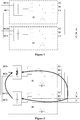
- In order to meet the requirement for high power, multiple topology units are connected in parallel in a power electronic converter system to achieve rapid expansion of capacity. As shown in
Figure 1 , input terminals of two topology units are connected in parallel, and output terminals of the two topology units are also connected in parallel. - However, due to the input terminals connected in parallel and the output terminals connected in parallel, a fault of one of the topology units in the power electronic converter system causes a fault current passing through the other topology unit as shown in
Figure 2 , resulting in a short circuit in the system, which damages the other topology unit. - Currently, as shown in
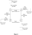
Figure 3 , fault protection may be performed by connecting a fuse in series in the topology unit. Alternatively, as shown inFigure 4 , a communication line may be established between topology units. Fault information is transmitted via the communication line when fault occurs in one topology unit, thereby avoiding damaging the other topology unit. - However, the inventers found that, with the fault protection shown in
Figure 3 , multiple fuses are required since the power electronic converter system generally includes multiple topology units. In addition, the fuse of a faulty topology needs to be replaced, increasing the cost of a power electronic converter and causing difficulties in maintenance. With the fault protection shown inFigure 4 , it is required to establish a communication line between the topology units, increasing cost of the system. In addition, since the communication line has low signal transmission efficiency, the topology units may not be protected due to a delayed communication signal. - Therefore, the technical problem that is urgently to be solved by those skilled in the art is how to provide a method and a system for protecting parallel-connected topology units for rapidly performing fault protection without increasing the cost of a converter system.
- In view of the above, a method and a system for protecting parallel-connected topology units are provided according to the embodiments of the present disclosure for rapidly performing fault protection without increasing the cost of a converter system.
- To achieve the above objective, following technical solutions are provided according to the embodiments the present disclosure.
- A method for protecting parallel-connected topology units, applied to a system for protecting parallel-connected topology units is provided. The system for protecting parallel-connected topology units includes topology units connected in parallel, each of the topology units includes a controller and a power module, the controller performs signal transmission with at least one of other controllers via a signal synchronization line, and the method for protecting parallel-connected topology units includes:
- obtaining a target signal transmitted via the signal synchronization line,
- sending the target signal to the other controllers based on a type of the target signal, and
- controlling a current power module to perform carrier synchronization and controlling the current power module to be in a working mode if the target signal is a carrier synchronization signal, and controlling the current power module to be in a shutdown mode if the target signal is a power module fault signal.
- In an embodiment, the method for protecting parallel-connected topology units further includes, if the target signal is the carrier synchronization signal, determining a fault state of the power module. If the fault state is a normal state, the target signal is transmitted to the other controllers, the current power module is controlled to perform carrier synchronization and is controlled to be in the working mode. If the fault state is a faulty state, the power module fault signal is sent to the other controllers and the current power module is controlled to be in the shutdown mode.
- In an embodiment, the controller is a single controller, the single controller is connected to the power module via a state acquisition signal line, the single controller acquires the power module fault signal sent by the power module and sends the power module fault signal via the signal synchronization line. Correspondingly, the obtaining the target signal transmitted via the signal synchronization line includes:
- acquiring, by the single controller, the carrier synchronization signal or the power module fault signal transmitted via the signal synchronization line, and
- determining the power module fault signal or the carrier synchronization signal as the target signal.
- In an embodiment, the controller includes a first sub-controller and a second sub-controller, the first sub-controller is connected to the second sub-controller via a feedback signal line, the second sub-controller performs signal transmission with at least one of other second sub-controllers via the signal synchronization line, and the second sub-controller is connected to the power module via a state acquisition signal line.
- Correspondingly, the second sub-controller obtains the target signal transmitted via the signal synchronization line.
- If the target signal is the carrier synchronization signal, the second sub-controller acquires a fault state of the power module via the state acquisition signal line. If the fault state is a normal state, the second sub-controller transmits the target signal to the other second sub-controllers via the signal synchronization line and transmits the target signal to the first sub-controller via the feedback signal line, and the first sub-controller performs carrier synchronization and controls the current power module to be in the working mode. If the fault state is a faulty state, the second sub-controller transmits the power module fault signal to the other second sub-controllers via the signal synchronization line and transmits the power module fault signal to the first sub-controller via the feedback signal line, and the first sub-controller controls the current power module to be in the shutdown mode.
- If the target signal is the power module fault signal, the second sub-controller sends the target signal to the other second sub-controllers via the signal synchronization line and transmits the target signal to the first sub-controller via the feedback signal line, and the first sub-controller controls the current power module to be in the shutdown mode.
- In an embodiment, the first sub-controller is a DSP and the second sub-controller is a CPLD.
- A device for protecting parallel-connected topology units applied to a system for protecting parallel-connected topology units is provided. The system for protecting parallel-connected topology units includes topology units connected in parallel, each of the topology units includes a controller and a power module, the controller performs signal transmission with at least one of other controllers via a signal synchronization line, and the device for protecting parallel-connected topology units includes an obtaining module, a sending module, and a control module.
- The obtaining module is configured to obtain a target signal transmitted via the signal synchronization line,
- The sending module is configured to send the target signal to the other controllers based on a type of the target signal.
- The control module is configured to control a current power module to perform carrier synchronization and control the current power module to be in a working mode if the target signal is a carrier synchronization signal, and control the current power module to be in a shutdown mode if the target signal is a power module fault signal.
- In an embodiment, the device for protecting parallel-connected topology units further includes a determining module. The determining module is configured to, if the target signal is the carrier synchronization signal, determine a fault state of the power module. The determining module is configured to transmit the target signal to the other controllers, control the current power module to perform carrier synchronization and control the current power module to be in the working mode if the fault state is a normal state, and send the power module fault signal to the other controllers and control the current power module to be in the shutdown mode if the fault state is a faulty state.
- In an embodiment, the controller is a single controller, the single controller is connected to the power module via a state acquisition signal line, the single controller acquires the power module fault signal sent by the power module and sends the power module fault signal via the signal synchronization line. The obtaining module includes: a first acquiring unit and a determining unit.
- The first acquiring unit is configured to acquire, by controller, the carrier synchronization signal or the power module fault signal transmitted via the signal synchronization line, and
The determining unit is configured to determine the power module fault signal or the carrier synchronization signal as the target signal. - A system for protecting parallel-connected topology units is provided. The system including topology units connected in parallel, each of the topology units includes a controller and a power module, the controller performs signal transmission with at least one of other controllers via a signal synchronization line.
- The controller obtains a target signal transmitted via the signal synchronization line.
- The controller sends the target signal to the other controllers based on a type of the target signal. The controller controls a current power module to perform carrier synchronization and controls the current power module to be in a working mode if the target signal is a carrier synchronization signal, and controls the current power module to be in a shutdown mode if the target signal is a power module fault signal.
- In an embodiment, the controller is a single controller, the single controller is connected to the power module via a state acquisition signal line, the single controller acquires the power module fault signal sent by the power module and sends the power module fault signal via the signal synchronization line. Correspondingly, the controller obtaining the target signal transmitted via the signal synchronization line includes the single controller being configured to:
acquire the carrier synchronization signal or the power module fault signal transmitted via the signal synchronization line, and determine the power module fault signal or the carrier synchronization signal as the target signal. - In an embodiment, the controller includes a first sub-controller and a second sub-controller, the first sub-controller is connected to the second sub-controller via a feedback signal line, the second sub-controller performs signal transmission with at least one of other second sub-controllers via the signal synchronization line, and the second sub-controller is connected to the power module via a state acquisition signal line. Correspondingly, the controller obtaining the target signal transmitted via the signal synchronization line includes:
- if the target signal is the carrier synchronization signal, the second sub-controller acquiring a fault state of the power module via the state acquisition signal line. If the fault state is a normal state, the second sub-controller transmits the target signal to the other second sub-controllers via the signal synchronization line and transmits the target signal to the first sub-controller via the feedback signal line, and the first sub-controller performs carrier synchronization and controls the current power module to be in the working mode. If the fault state is a faulty state, the second sub-controller transmits the power module fault signal to the other second sub-controllers via the signal synchronization line and transmits the power module fault signal to the first sub-controller via the feedback signal line, and the first sub-controller controls the current power module to be in the shutdown mode.
- If the target signal is the power module fault signal, the second sub-controller sends the target signal to the other second sub-controllers via the signal synchronization line and transmits the target signal to the first sub-controller via the feedback signal line, and the first sub-controller controls the current power module to be in the shutdown mode.
- In an embodiment, the first sub-controller is a DSP and the second sub-controller is a CPLD.
- Based on the above technical solutions, the method for protecting parallel-connected topology units, applied to a system for protecting parallel-connected topology units, is provided according to the embodiments of the present disclosure. The system for protecting parallel-connected topology units includes topology units connected in parallel. Each of the topology units includes a controller and a power module. The controller performs signal transmission with at least one of other controllers via a signal synchronization line. In the method for protecting parallel-connected topology units, the target signal transmitted via the signal synchronization line is first obtained, and the target signal is sent to the other controllers based on a type of the target signal. If the target signal is the carrier synchronization signal, the current power module is controlled to perform carrier synchronization and is controlled to be in a working mode. If the target signal is the power module fault signal, the current power module is controlled to be in the shutdown mode. It can be seen that in the present disclosure, the signal synchronization lines between the topology units connected in parallel are shared in a time-sharing manner. The carrier synchronization signal is transmitted via the signal synchronization line if the power module works normally, and the power module fault signal is transmitted via the signal synchronization line if the power module is faulty. Each of the topology units monitors the transmitted target signal in a real time manner to achieve fast synchronous protection.
- The drawings to be used in the description of the embodiments or the conventional technology are described briefly as follows, so that the technical solutions according to the embodiments of the present disclosure or according to the conventional technology become clearer. It is apparent that the drawings in the following description only illustrate some embodiments of the present disclosure. For those skilled in the art, other drawings may be obtained according to these drawings without any creative work.
-
Figure 1 is a schematic structural diagram of a topology unit in the conventional technology; -
Figure 2 is a schematic diagram of a faulty topology unit in the conventional technology; -
Figure 3 is a schematic structural diagram of another topology unit in the conventional technology; -
Figure 4 is a schematic structural diagram of another topology unit in the conventional technology; -
Figure 5 is a schematic structural diagram of a system for protecting parallel-connected topology units according to an embodiment of the present disclosure; -
Figure 6 is a schematic structural diagram of a topology unit according to an embodiment of the present disclosure; -
Figure 7 is a flow chart of a method for protecting parallel-connected topology units according to an embodiment of the present disclosure; -
Figure 8 is a flow chart of a method for protecting parallel-connected topology units according to another embodiment of the present disclosure; -
Figure 9 is a schematic structural diagram of a topology unit according to another embodiment of the present disclosure; -
Figure 10 is a flow chart of a method for protecting parallel-connected topology units according to another embodiment of the present disclosure; -
Figure 11 is a schematic structural diagram of a topology unit according to another embodiment of the present disclosure; -
Figure 12 is a flow chart of a method for protecting parallel-connected topology units according to another embodiment of the present disclosure; -
Figure 13 is a flow chart of a method for protecting parallel-connected topology units according to another embodiment of the present disclosure; -
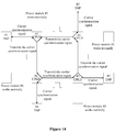
Figure 14 is a schematic structural diagram of a topology unit according to another embodiment of the present disclosure; -
Figure 15 is a schematic structural diagram of a topology unit according to another embodiment of the present disclosure; -
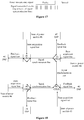
Figure 16 is a schematic diagram of a carrier synchronization signal and a power module fault signal according to an embodiment of the present disclosure; -
Figure 17 is a schematic diagram of a carrier synchronization signal and a power module fault signal according to another embodiment of the present disclosure; and -
Figure 18 is a schematic structural diagram of a topology unit according to another embodiment of the present disclosure. - Reference is made to
Figure 5 , which is a schematic structural diagram of a system for protecting parallel-connected topology units according to an embodiment of the present disclosure. The system for protecting parallel-connected topology units includes multiple topology units connected in parallel. Signal synchronization lines are arranged between the multiple topology units for transmitting carrier synchronization signals, thereby implementing PWM carrier synchronization and suppressing circulating currents. In the embodiment, the topology unit may be an inverter unit, a rectifier, or a DC/DC converter. In this embodiment, an inverter unit is used as an example of the topology unit for describing the principle of a method for protecting parallel-connected topology units according to the present disclosure. In addition, the signal synchronization lines may be implemented by optical fibers or wires for transmitting an optical signal or an electrical signal at high transmission rates. - Based on this, as shown in
Figure 6 , the topology unit includes a controller and a power module. The controller is a single controller. The single controller is connected to the power module via a state acquisition signal line to acquire a power module fault signal sent by the power module and sends the power module fault signal via the signal synchronization line. In this embodiment, the single controller may be implemented as any CPU. - Based on the system for protecting parallel-connected topology units, a method for protecting parallel-connected topology units is provided according to an embodiment. As shown in
Figure 7 , the method includes following steps S1 to S4. - In step S1, a target signal transmitted via the signal synchronization line is obtained.
- In step S2, the target signal is sent to the other controllers based on a type of the target signal.
- In step S3, a current power module is controlled to perform carrier synchronization and controlled to be in a working mode if the target signal is a carrier synchronization signal.
- In step S4, the current power module is controlled to be in a shutdown mode if the target signal is a power module fault signal.
- In this embodiment, the controller CPU detects the type of the target signal transmitted via the signal synchronization line. If the target signal transmitted via the signal synchronization line is the carrier synchronization signal, the controller CPU performs PWM carrier synchronization and causes the current power module, that is, the power module connected to the controller CPU, to operate normally. If the target signal transmitted via the signal synchronization line is a power module fault signal, the controller CPU controls the current power module to be in a shutdown mode.
- It can be seen that according to the present disclosure, the signal synchronization lines between the topology units connected in parallel are shared in a time-sharing manner. The carrier synchronization signal is transmitted through the signal synchronization line if the power module work normally, and the power module fault signal is transmitted through the signal synchronization line if the power module is faulty. Each of the topology units monitors the transmitted target signal in a real-time manner to achieve fast synchronous protection.
- Based on the above embodiments, as shown in
Figure 8 , if the target signal is the carrier synchronization signal, the method according to the embodiment further includes following steps S31 to S33. - In step S31, a fault state of the power module is determined.
- In step S32, if the fault state is a normal state, the target signal is transmitted to the other controllers, and the current power module is controlled to perform carrier synchronization and is controlled to be in the working mode.
- In step S33, if the fault state is a faulty state, the power module fault signal is sent to the other controllers and the current power module is controlled to be in the shutdown mode.
- In this embodiment, the controller CPU detects the type of the target signal transmitted via the signal synchronization line. If the target signal transmitted via the signal synchronization line is the carrier synchronization signal, the controller CPU detects whether the power module in the topology unit where the controller CPU is located is faulty via the state acquisition signal line. If all power modules operate normally, the controller CPU transmits the carrier synchronization signal to a next controller. The controller CPU performs PWM carrier synchronization and causes the power module to operate normally. If the power module is faulty, the controller CPU suspends sending the carrier synchronization signal and sends the power module fault signal via the signal synchronization line. If the target signal transmitted via the signal synchronization line is the power module fault signal, the power module fault signal is transparently transmitted to the next controller. The controller CPU receives the power module fault signal and the power module is shut down for protection.
- In an embodiment, multiple controllers may form a ring signal network by using the signal synchronization lines. As shown in
Figure 6 , a controller CPU1 transmits the target signal to a controller CPU2 via a signal synchronization line, the controller CPU2 transmits the target signal to a controller CPU3 via a signal synchronization line, the controller CPU3 transmits the target signal to a controller CPU4 via a signal synchronization line, and the controller CPU4 transmits the target signal to the controller CPU1 via a signal synchronization line. - Alternatively, multiple controllers may form a non-ring signal network via signal synchronization lines. As shown in
Figure 9 , a controller CPU1 transmits the target signal to a controller CPU2 via a signal synchronization line, the controller CPU2 transmits the target signal to a controller CPU3 via a signal synchronization line, and the controller CPU3 transmits the target signal to a controller CPU4 via a signal synchronization line. The controller CPU4 does not transmit the target signal to the controller CPU1 via a signal synchronization line. - Based on the above embodiments, an implementation for obtaining the target signal transmitted via the signal synchronization line is provided according to an embodiment of the present disclosure. As shown in
Figure 10 , the implementation includes following step S101 and S102. - In step S101, the single controller acquires the carrier synchronization signal or the power module fault signal transmitted via the signal synchronization line.
- In step S102, the power module fault signal or the carrier synchronization signal is determined as the target signal.
- In a normal state, the carrier synchronization signal is transmitted via the signal synchronization line. In this case, the target signal is the carrier synchronization signal, for performing PWM carrier synchronization. If the power module fault signal is transmitted via the signal synchronization line, the target signal is the power module fault signal, for notifying another controller to control the corresponding power module to be shut down.
- In an embodiment, as shown in
Figure 11 , the controller may be a combination of a first sub-controller and a second sub-controller. In this embodiment, the first sub-controller is defined as a main controller DSP, and the second sub-controller is defined as an auxiliary controller CPLD, the first sub-controller is connected to the second sub-controller via a feedback signal line, the second sub-controller is connected to at least one of other second sub-controllers via the signal synchronization line, and the second sub-controller is connected to the power module via the state acquisition signal line. - Correspondingly, as shown in
Figure 12 , another implementation for obtaining the target signal transmitted via the signal synchronization line is provided according to an embodiment of the present disclosure. The implementation includes following step S121 and S123. - In step S121, the second sub-controller obtains the target signal transmitted via the signal synchronization line.
- In step S122, if the target signal is the carrier synchronization signal, the second sub-controller acquires the fault state of the power module via the state acquisition signal line. If the fault state is the normal state, the second sub-controller transmits the target signal to the other second sub-controllers via the signal synchronization line and transmits the target signal to the first sub-controller via the feedback signal line, and the first sub-controller controls the current power module to perform carrier synchronization and controls the current power module to be in the working mode. If the fault state is a faulty state, the second sub-controller transmits the power module fault signal to the other second sub-controllers via the signal synchronization line and transmits the power module fault signal to the first sub-controller via the feedback signal line, and the first sub-controller controls the current power module to be in the shutdown mode.
- In step S123, if the target signal is the power module fault signal, the second sub-controller sends the target signal to the other second sub-controllers via the signal synchronization line and transmits the target signal to the first sub-controller via the feedback signal line, and the first sub-controller controls the current power module to be in the shutdown mode.
- It should be noted that in this embodiment, the second sub-controller may constantly acquire the fault state of the power module via the state acquisition signal line. The acquisition of the fault state is not limited to being performed in the case that the target signal is the carrier synchronization signal.
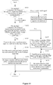
- A method for protecting parallel-connected topology units is provided according to another embodiment of the present disclosure. As shown in
Figure 13 , the method includes following steps S131 to S139. - In step S131, an auxiliary controller CPLD detects the type of a signal transmitted via a ring network of signal synchronization lines.
- In step S132, if the carrier synchronization signal is transmitted via the ring network, the auxiliary controller CPLD detects whether the power module in the unit where the auxiliary controller CPLD is located is faulty via the state acquisition signal line.
- In step S133, if none of other power modules in the ring network and the power module in the unit where the auxiliary controller CPLD is located is faulty, the carrier synchronization signal is transmitted to a next unit in the ring network.
- In step S134, the carrier synchronization signal is sent to the main controller DSP via the feedback signal line.
- In step S135, the main controller DSP performs PWM carrier synchronization and the power module runs normally.
- In step S136, if the power module fault signal is transmitted via the ring network, the power module fault signal is transparently transmitted to the next unit.
- In step S137, if the power module in the unit where the auxiliary controller CPLD is located is faulty, the auxiliary controller CPLD suspends sending the carrier synchronization signal and sends the power module fault signal via the ring network.
- In step S138, the power module fault signal is sent to the main controller DSP via the feedback signal line.
- In step S139, the main controller DSP receives the power module fault signal, and the power module is shut down for protection.
- Referring to
Figure 14 , if the power module works normally, the power module fault signal is not detected by auxiliary controllers CPLD in all the units, and the carrier synchronization signal is transmitted via the ring network of signal synchronization lines. On reception of the carrier synchronization signal, the auxiliary controllers CPLD feed the carrier synchronization signal back to respective main controllers DSP to ensure PWM carrier synchronization and normal operation of all the units. - If the power module in one of the topology units (for example, #1) is faulty, the auxiliary controller CPLD in the topology unit detects the power module fault signal, suspends sending the carrier synchronization signal and sends the power module fault signal, for example, high-frequency pulses, via the ring network of signal synchronization lines. As shown in
Figure 15 , on reception of the power module fault signal, auxiliary controllers CPLD in other units transparently transmit the power module fault signal to a next unit in the ring network, and feed the power module fault signal back to respective main controllers DSP. - It should be noted that in this embodiment, if the power module switches from the normal state to the faulty state, the signal transmitted via the signal synchronization line is changed from the carrier synchronization pulse to the power module fault signal, for example, as shown in
Figure 16 , changed from low-frequency pulses to high-frequency pulses. When the fault of the power module is cleared, the carrier synchronization signal is transmitted via the ring network of signal synchronization lines, for example, as shown inFigure 17 , the high-frequency pulses is replaced by low-frequency pulses. - The carrier synchronization signal and the power module fault signal may be signals in other forms. In addition, if the controller includes a first sub-controller and a second sub-controller, all the second sub-controllers may be connected into a ring network as shown in
Figure 11 or may be connected into a non-ring network as shown inFigure 18 . - Based on the above embodiments, a device for protecting parallel-connected topology units applied to a system for protecting parallel-connected topology units is provided according to an embodiment. The system for protecting parallel-connected topology units includes topology units connected in parallel, each of the topology units includes a controller and a power module, the controller performs signal transmission with at least one of other controllers via a signal synchronization line, and the device for protecting parallel-connected topology units includes: an obtaining module, a sending module, and a control module.
- The obtaining module is configured to obtain a target signal transmitted via the signal synchronization line.
- The sending module is configured to send the target signal to the other controllers based on a type of the target signal.
- The control module is configured to control a current power module to perform carrier synchronization and control the current power module to be in a working mode if the target signal is a carrier synchronization signal, and control the current power module to be in a shutdown mode if the target signal is a power module fault signal.
- The device for protecting parallel-connected topology units according to this embodiment may further include a determining module.
- The determining module is configured to, if the target signal is the carrier synchronization signal, determine a fault state of the power module. The determining module is configured to, if the fault state is a normal state, transmit the target signal to the other controllers, control the current power module to perform carrier synchronization and control the current power module to be in the working mode, and if the fault state is a faulty state, send the power module fault signal to the other controllers and control the current power module to be in the shutdown mode.
- In an embodiment, the controller is a single controller, the single controller is connected to the power module via a state acquisition signal line, the single controller acquires the power module fault signal sent by the power module and sends the power module fault signal via the signal synchronization line. Correspondingly, the obtaining module includes: a first acquiring unit and a determining unit.
- The first acquiring unit is configured to acquire, by controller, the carrier synchronization signal or the power module fault signal transmitted via the signal synchronization line.
- The determining unit is configured to determine the power module fault signal or the carrier synchronization signal as the target signal.
- One can refer to the above method embodiments for the working principle of the device, which is not repeated herein.
- In addition, a system for protecting parallel-connected topology units is provided. The system including topology units connected in parallel, each of the topology units includes a controller and a power module, the controller performs signal transmission with at least one of other controllers via a signal synchronization line.
- The controller obtains a target signal transmitted via the signal synchronization line.
- The controller sends the target signal to the other controllers based on a type of the target signal. The controller controls a current power module to perform carrier synchronization and controls the current power module to be in a working mode if the target signal is a carrier synchronization signal, and controls the current power module to be in a shutdown mode if the target signal is a power module fault signal.
- In an embodiment, the controller is a single controller, the single controller is connected to the power module via a state acquisition signal line, the single controller acquires the power module fault signal sent by the power module and sends the power module fault signal via the signal synchronization line. Correspondingly, the controller obtaining the target signal transmitted via the signal synchronization line includes the single controller being configured to:
acquire the carrier synchronization signal or the power module fault signal transmitted via the signal synchronization line, and determine the power module fault signal or the carrier synchronization signal as the target signal. - In an embodiment, the controller includes a first sub-controller and a second sub-controller, the first sub-controller is connected to the second sub-controller via a feedback signal line, the second sub-controller performs signal transmission with at least one of other second sub-controllers via the signal synchronization line, and the second sub-controller is connected to the power module via a state acquisition signal line. Correspondingly, the controller obtaining the target signal transmitted via the signal synchronization line includes:
if the target signal is the carrier synchronization signal, the second sub-controller acquiring a fault state of the power module via the state acquisition signal line. If the fault state is a normal state, the second sub-controller transmits the target signal to the other second sub-controllers via the signal synchronization line and transmits the target signal to the first sub-controller via the feedback signal line, and the first sub-controller controls the current power module to perform carrier synchronization and controls the current power module to be in the working mode. If the fault state is a faulty state, the second sub-controller transmits the power module fault signal to the other second sub-controllers via the signal synchronization line and transmits the power module fault signal to the first sub-controller via the feedback signal line, and the first sub-controller controls the current power module to be in the shutdown mode. - If the target signal is the power module fault signal, the second sub-controller sends the target signal to the other second sub-controllers via the signal synchronization line and transmits the target signal to the first sub-controller via the feedback signal line, and the first sub-controller controls the current power module to be in the shutdown mode.
- It can be seen that in the system for protecting parallel-connected topology units, the signal synchronization lines between the topology units connected in parallel are shared in a time-sharing manner. The carrier synchronization signal is transmitted via the signal synchronization line if the power module works normally, and the power module fault signal is transmitted via the signal synchronization line if the power module is faulty. Each of the topology units monitors the transmitted target signal in a real time manner to achieve fast synchronous protection.
- In summary, a method, a device, and a system for protecting parallel-connected topology units are provided according to the present disclosure. The target signal transmitted via the signal synchronization line is first obtained, and the target signal is sent to the other controllers based on a type of the target signal. If the target signal is the carrier synchronization signal, the current power module is controlled to perform carrier synchronization and is controlled to be in a working mode. If the target signal is the power module fault signal, the current power module is controlled to be in the shutdown mode. It can be seen that in the present disclosure, the signal synchronization lines between the topology units connected in parallel are shared in a time-sharing manner. The carrier synchronization signal is transmitted via the signal synchronization line if the power module works normally, and the power module fault signal is transmitted via the signal synchronization line if the power module is faulty. Each of the topology units monitors the transmitted target signal in a real time manner to achieve fast synchronous protection.
- The embodiments in this specification are described in a progressive way, each of which emphasizes the differences from others, and the same or similar parts among the embodiments can be referred to each other. Since the device disclosed in the embodiments corresponds to the method therein, the description thereof is relatively simple, and for relevant matters references may be made to the description of the method.
- It may be known by those skilled in the art that, units and algorithm steps in each examples described in conjunction with the embodiments disclosed herein can be realized by electronic hardware, computer software or a combination thereof. In order to clearly illustrate interchangeability of the hardware and the software, steps and composition of each embodiment have been described generally in view of functions in the above specification. Whether the function is executed in a hardware way or in a software way depends on application of the technical solution and design constraint condition. Those skilled in the art can use different method for each application to realize the described function, and this is not considered to be beyond the scope of the application.
- The steps of the methods or algorithms described in conjunction with the embodiments of the present disclosure can be implemented with hardware, software modules executed by a processor, or a combination thereof. The software modules may reside in a Random Access Memory (RAM), an internal memory, a Read Only Memory (ROM), an Electrically Programmable ROM, an Electrically-Erasable Programmable ROM, a register, a hard disk, a removable disk drive, CD-ROM, or other types of storage media well known in the technical field.
- With the above descriptions of the disclosed embodiments, the skilled in the art may practice or use the present disclosure. Various modifications to the embodiments are apparent for the skilled in the art. The general principle suggested herein can be implemented in other embodiments without departing from the spirit or scope of the disclosure. Therefore, the present disclosure should not be limited to the embodiments disclosed herein, but has the widest scope that is conformity with the principle and the novel features disclosed herein.
Claims (10)
- A method for protecting parallel-connected topology units, applied to a system for protecting parallel-connected topology units, wherein the system for protecting parallel-connected topology units comprises topology units connected in parallel, each of the topology units comprises a controller and a power module, the controller performs signal transmission with at least one of other controllers via a signal synchronization line, and the method for protecting parallel-connected topology units comprises:obtaining a target signal transmitted via the signal synchronization line,sending the target signal to the other controllers based on a type of the target signal, andcontrolling a current power module to perform carrier synchronization and controlling the current power module to be in a working mode if the target signal is a carrier synchronization signal, and controlling the current power module to be in a shutdown mode if the target signal is a power module fault signal.
- The method for protecting parallel-connected topology units according to claim 1, further comprising, if the target signal is the carrier synchronization signal:determining a fault state of the power module,if the fault state is a normal state, transmitting the target signal to the other controllers, controlling the current power module to perform carrier synchronization and controlling the current power module to be in the working mode, andif the fault state is a faulty state, sending the power module fault signal to the other controllers and controlling the current power module to be in the shutdown mode.
- The method for protecting parallel-connected topology units according to claim 1, wherein
the controller is a single controller, the single controller is connected to the power module via a state acquisition signal line, the single controller acquires the power module fault signal sent by the power module and sends the power module fault signal via the signal synchronization line, and
the obtaining the target signal transmitted via the signal synchronization line comprises:acquiring, by the single controller, the carrier synchronization signal or the power module fault signal transmitted via the signal synchronization line, anddetermining the power module fault signal or the carrier synchronization signal as the target signal. - The method for protecting parallel-connected topology units according to claim 1, wherein
the controller comprises a first sub-controller and a second sub-controller, the first sub-controller is connected to the second sub-controller via a feedback signal line, the second sub-controller performs signal transmission with at least one of other second sub-controllers via the signal synchronization line, and the second sub-controller is connected to the power module via a state acquisition signal line, and
the second sub-controller obtains the target signal transmitted via the signal synchronization line, if the target signal is the carrier synchronization signal, the second sub-controller acquires a fault state of the power module via the state acquisition signal line, wherein
if the fault state is a normal state, the second sub-controller transmits the target signal to the other second sub-controllers via the signal synchronization line and transmits the target signal to the first sub-controller via the feedback signal line, and the first sub-controller performs carrier synchronization and controls the current power module to be in the working mode, and
if the fault state is a faulty state, the second sub-controller transmits the power module fault signal to the other second sub-controllers via the signal synchronization line and transmits the power module fault signal to the first sub-controller via the feedback signal line, and the first sub-controller controls the current power module to be in the shutdown mode,
if the target signal is the power module fault signal, the second sub-controller sends the target signal to the other second sub-controllers via the signal synchronization line and transmits the target signal to the first sub-controller via the feedback signal line, and the first sub-controller controls the current power module to be in the shutdown mode. - A device for protecting parallel-connected topology units, applied to a system for protecting parallel-connected topology units, wherein the system for protecting parallel-connected topology units comprises topology units connected in parallel, each of the topology units comprises a controller and a power module, the controller performs signal transmission with at least one of other controllers via a signal synchronization line, and the device for protecting parallel-connected topology units comprises:an obtaining module configured to obtain a target signal transmitted via the signal synchronization line,a sending module configured to send the target signal to the other controllers based on a type of the target signal, anda control module configured to control a current power module to perform carrier synchronization and control the current power module to be in a working mode if the target signal is a carrier synchronization signal, and control the current power module to be in a shutdown mode if the target signal is a power module fault signal.
- The device for protecting parallel-connected topology units according to claim 5, further comprising:
a determining module configured to, if the target signal is the carrier synchronization signal, determine a fault state of the power module, whereinthe determining module is configured to,
if the fault state is a normal state, transmit the target signal to the other controllers, control the current power module to perform carrier synchronization and control the current power module to be in the working mode, andif the fault state is a faulty state, send the power module fault signal to the other controllers and control the current power module to be in the shutdown mode. - The device for protecting parallel-connected topology units according to claim 5, wherein
the controller is a single controller, the single controller is connected to the power module via a state acquisition signal line, the single controller acquires the power module fault signal sent by the power module and sends the power module fault signal via the signal synchronization line, and the obtaining module comprises:a first acquiring unit configured to acquire, by controller, the carrier synchronization signal or the power module fault signal transmitted via the signal synchronization line, anda determining unit configured to determine the power module fault signal or the carrier synchronization signal as the target signal. - A system for protecting parallel-connected topology units, comprising topology units connected in parallel, each of the topology units comprises a controller and a power module, the controller performs signal transmission with at least one of other controllers via a signal synchronization line, and the controller:obtains a target signal transmitted via the signal synchronization line,sends the target signal to the other controllers based on a type of the target signal, andcontrols a current power module to perform carrier synchronization and controls the current power module to be in a working mode if the target signal is a carrier synchronization signal, and controls the current power module to be in a shutdown mode if the target signal is a power module fault signal.
- The system for protecting parallel-connected topology units according to claim 8, wherein
the controller is a single controller, the single controller is connected to the power module via a state acquisition signal line, the single controller acquires the power module fault signal sent by the power module and sends the power module fault signal via the signal synchronization line, and the controller obtaining the target signal transmitted via the signal synchronization line comprises the single controller being configured to:acquire the carrier synchronization signal or the power module fault signal transmitted via the signal synchronization line, anddetermine the power module fault signal or the carrier synchronization signal as the target signal. - The system for protecting parallel-connected topology units according to claim 8, wherein
the controller comprises a first sub-controller and a second sub-controller, the first sub-controller is connected to the second sub-controller via a feedback signal line, the second sub-controller performs signal transmission with at least one of other second sub-controllers via the signal synchronization line, and the second sub-controller is connected to the power module via a state acquisition signal line, and the controller obtaining the target signal transmitted via the signal synchronization line comprises:if the target signal is the carrier synchronization signal, the second sub-controller acquiring a fault state of the power module via the state acquisition signal line, whereinif the fault state is a normal state, the second sub-controller transmits the target signal to the other second sub-controllers via the signal synchronization line and transmits the target signal to the first sub-controller via the feedback signal line, and the first sub-controller performs carrier synchronization and controls the current power module to be in the working mode, andif the fault state is a faulty state, the second sub-controller transmits the power module fault signal to the other second sub-controllers via the signal synchronization line and transmits the power module fault signal to the first sub-controller via the feedback signal line, and the first sub-controller controls the current power module to be in the shutdown mode,if the target signal is the power module fault signal, the second sub-controller sends the target signal to the other second sub-controllers via the signal synchronization line and transmits the target signal to the first sub-controller via the feedback signal line, and the first sub-controller controls the current power module to be in the shutdown mode.
Applications Claiming Priority (2)
| Application Number | Priority Date | Filing Date | Title |
|---|---|---|---|
| CN201910237668.0A CN109787464B (en) | 2019-03-27 | 2019-03-27 | Topological unit parallel protection method, device and system |
| PCT/CN2019/130494 WO2020192224A1 (en) | 2019-03-27 | 2019-12-31 | Topology unit parallel-connection protection method, device and system |
Publications (2)
| Publication Number | Publication Date |
|---|---|
| EP3748829A1 true EP3748829A1 (en) | 2020-12-09 |
| EP3748829A4 EP3748829A4 (en) | 2022-01-26 |
Family
ID=66491259
Family Applications (1)
| Application Number | Title | Priority Date | Filing Date |
|---|---|---|---|
| EP19897575.7A Pending EP3748829A4 (en) | 2019-03-27 | 2019-12-31 | METHOD, DEVICE AND SYSTEM FOR PROTECTION OF PARALLEL CONNECTION OF TOPOLOGICAL UNITS |
Country Status (5)
| Country | Link |
|---|---|
| US (1) | US11387643B2 (en) |
| EP (1) | EP3748829A4 (en) |
| JP (1) | JP7028512B2 (en) |
| CN (1) | CN109787464B (en) |
| WO (1) | WO2020192224A1 (en) |
Families Citing this family (3)
| Publication number | Priority date | Publication date | Assignee | Title |
|---|---|---|---|---|
| CN109787464B (en) * | 2019-03-27 | 2022-07-12 | 阳光电源股份有限公司 | Topological unit parallel protection method, device and system |
| EP3886897A1 (en) | 2020-02-04 | 2021-10-06 | CureVac AG | Coronavirus vaccine |
| CN118677238B (en) * | 2023-03-16 | 2025-11-04 | 比亚迪股份有限公司 | Control method of power factor correction circuit |
Family Cites Families (19)
| Publication number | Priority date | Publication date | Assignee | Title |
|---|---|---|---|---|
| US3823362A (en) * | 1973-02-02 | 1974-07-09 | Gen Electric | Coordinated master-slave converter system for variable-power tank loads |
| DE2742997C2 (en) * | 1977-09-22 | 1982-08-26 | Licentia Patent-Verwaltungs-Gmbh, 6000 Frankfurt | Procedure for overcurrent protection of inverters in high-voltage direct current transmission systems |
| JPH081350A (en) | 1994-06-17 | 1996-01-09 | Toshiba Corp | Inverter resistance welding machine parallel system |
| US6285572B1 (en) * | 1999-04-20 | 2001-09-04 | Sanyo Electric Co., Ltd. | Method of operating a power supply system having parallel-connected inverters, and power converting system |
| JP2005176558A (en) | 2003-12-15 | 2005-06-30 | Taiyo Yuden Co Ltd | Multi-output power supply device |
| EP1575156B1 (en) * | 2004-02-16 | 2015-06-17 | Vacon Oyj | Synchronization of parallel-connected inverter units or frequency converters |
| JP5787127B2 (en) * | 2010-09-03 | 2015-09-30 | 富士電機株式会社 | Power converter protection circuit |
| JP5615734B2 (en) | 2011-02-23 | 2014-10-29 | 株式会社日立製作所 | Control device for parallel multiple power converter |
| CN203117691U (en) | 2013-01-21 | 2013-08-07 | 中国人民解放军63963部队 | An intelligent power module and a high-voltage power switch |
| CN103368182B (en) * | 2013-08-08 | 2015-01-21 | 东南大学 | Modularized multi-machine parallel-connection large-power APF (active power filter) control system and realization method |
| CN104486059B (en) * | 2015-01-04 | 2018-07-03 | 阳光电源股份有限公司 | A kind of photovoltaic DC-to-AC converter parallel system carrier synchronization method and device |
| US9762143B2 (en) * | 2015-04-29 | 2017-09-12 | Toshiba Mitsubishi-Electric Industrial Systems Corporation | Devices and methods for controlling current in inverters |
| CN104950765B (en) | 2015-06-23 | 2017-09-22 | 合肥工业大学 | A kind of inverter parallel system and its carrier synchronization method based on CAN |
| CN105391089B (en) * | 2015-12-21 | 2018-06-26 | 中国西电电气股份有限公司 | The control method for parallel and circuit of a kind of inverter |
| CN105743634B (en) * | 2016-03-28 | 2019-02-01 | 阳光电源股份有限公司 | A parallel device system and its carrier synchronization control method |
| CN106067848A (en) * | 2016-07-25 | 2016-11-02 | 易事特集团股份有限公司 | Microgrid inverter phase-shifting carrier wave synchronizes system and phase-shifting carrier wave synchronous method |
| JP2019024300A (en) | 2017-07-21 | 2019-02-14 | 富士電機株式会社 | Power conversion system |
| CN109302091B (en) * | 2018-12-03 | 2020-09-22 | 中冶南方(武汉)自动化有限公司 | An AC drive inverter parallel control system and method |
| CN109787464B (en) | 2019-03-27 | 2022-07-12 | 阳光电源股份有限公司 | Topological unit parallel protection method, device and system |
-
2019
- 2019-03-27 CN CN201910237668.0A patent/CN109787464B/en active Active
- 2019-12-31 WO PCT/CN2019/130494 patent/WO2020192224A1/en not_active Ceased
- 2019-12-31 US US16/959,982 patent/US11387643B2/en active Active
- 2019-12-31 JP JP2020528884A patent/JP7028512B2/en active Active
- 2019-12-31 EP EP19897575.7A patent/EP3748829A4/en active Pending
Also Published As
| Publication number | Publication date |
|---|---|
| CN109787464A (en) | 2019-05-21 |
| CN109787464B (en) | 2022-07-12 |
| WO2020192224A1 (en) | 2020-10-01 |
| US20210257830A1 (en) | 2021-08-19 |
| JP7028512B2 (en) | 2022-03-02 |
| EP3748829A4 (en) | 2022-01-26 |
| JP2021520175A (en) | 2021-08-12 |
| US11387643B2 (en) | 2022-07-12 |
Similar Documents
| Publication | Publication Date | Title |
|---|---|---|
| US11081885B2 (en) | Battery energy storage grid-load interactive method, terminal, system and medium for superimposed control | |
| US11334136B1 (en) | Power loss siren | |
| US20160064938A1 (en) | Dynamically Configurable Power-Over-Ethernet Apparatus and Method | |
| US11387643B2 (en) | Method, device and system for protecting parallel-connected topology units | |
| CN104486059B (en) | A kind of photovoltaic DC-to-AC converter parallel system carrier synchronization method and device | |
| EP4057471B1 (en) | PHOTOVOLTAIC SYSTEM AND METHOD FOR SETTING AN OPTIMIZER'S OPERATING STATE | |
| JP6904026B2 (en) | Power system, control method, and control program | |
| CN119182174A (en) | Master-slave control motor micro-grid host autonomous distribution method and system | |
| JP2014220551A (en) | Node device and optical communication system | |
| CN121097791A (en) | Control method, control device and storage medium for multi-inverter parallel operation system | |
| US8965993B2 (en) | Entrusted management method for a plurality of rack systems | |
| CN109149777A (en) | A kind of shutdown control system and method | |
| CN119828446A (en) | Electrical control device for an underwater vehicle | |
| US20190250687A1 (en) | Method for Monitoring, Control and Graceful Shutdown of Control and/or Computer Units | |
| CN117032186B (en) | Controller system with power supply abnormality early warning protection function | |
| CN114335764B (en) | Control method and device, energy storage system and non-volatile computer readable storage medium | |
| CN108650068B (en) | Synchronous signal transmission method and system for parallel operation of uninterruptible power supplies | |
| CN109245298A (en) | A kind of shutdown control system and method | |
| JP2011227786A (en) | Microcomputer control system, charging device using the same and photovoltaic power supply system | |
| CN210807323U (en) | Redundant dual master control network device | |
| CN120896246B (en) | Grid-connected power scheduling synchronization method for inversion parallel operation system | |
| CN220421644U (en) | Power supply system | |
| CN219937962U (en) | New energy control system | |
| CN119051191B (en) | Energy storage system and communication control method thereof | |
| CN106020304A (en) | Self-adaptive master slave multimode type parallel operation current-sharing control method |
Legal Events
| Date | Code | Title | Description |
|---|---|---|---|
| STAA | Information on the status of an ep patent application or granted ep patent |
Free format text: STATUS: UNKNOWN |
|
| STAA | Information on the status of an ep patent application or granted ep patent |
Free format text: STATUS: THE INTERNATIONAL PUBLICATION HAS BEEN MADE |
|
| PUAI | Public reference made under article 153(3) epc to a published international application that has entered the european phase |
Free format text: ORIGINAL CODE: 0009012 |
|
| STAA | Information on the status of an ep patent application or granted ep patent |
Free format text: STATUS: REQUEST FOR EXAMINATION WAS MADE |
|
| 17P | Request for examination filed |
Effective date: 20200902 |
|
| AK | Designated contracting states |
Kind code of ref document: A1 Designated state(s): AL AT BE BG CH CY CZ DE DK EE ES FI FR GB GR HR HU IE IS IT LI LT LU LV MC MK MT NL NO PL PT RO RS SE SI SK SM TR |
|
| AX | Request for extension of the european patent |
Extension state: BA ME |
|
| A4 | Supplementary search report drawn up and despatched |
Effective date: 20220104 |
|
| RIC1 | Information provided on ipc code assigned before grant |
Ipc: H02M 1/32 20070101AFI20211221BHEP |
|
| DAV | Request for validation of the european patent (deleted) | ||
| DAX | Request for extension of the european patent (deleted) | ||
| STAA | Information on the status of an ep patent application or granted ep patent |
Free format text: STATUS: EXAMINATION IS IN PROGRESS |
|
| 17Q | First examination report despatched |
Effective date: 20230512 |