EP3748658B1 - Agencement de contacts pour résistance de pré-insertion - Google Patents
Agencement de contacts pour résistance de pré-insertion Download PDFInfo
- Publication number
- EP3748658B1 EP3748658B1 EP19178265.5A EP19178265A EP3748658B1 EP 3748658 B1 EP3748658 B1 EP 3748658B1 EP 19178265 A EP19178265 A EP 19178265A EP 3748658 B1 EP3748658 B1 EP 3748658B1
- Authority
- EP
- European Patent Office
- Prior art keywords
- movable contact
- tulip
- control rod
- latching ring
- pir
- Prior art date
- Legal status (The legal status is an assumption and is not a legal conclusion. Google has not performed a legal analysis and makes no representation as to the accuracy of the status listed.)
- Active
Links
- 238000003780 insertion Methods 0.000 title claims description 9
- 230000037431 insertion Effects 0.000 title 1
- 241000722921 Tulipa gesneriana Species 0.000 claims description 50
- 230000015572 biosynthetic process Effects 0.000 claims description 22
- 238000005755 formation reaction Methods 0.000 claims description 22
- 238000000034 method Methods 0.000 claims description 7
- 230000006835 compression Effects 0.000 claims description 3
- 238000007906 compression Methods 0.000 claims description 3
- 229910001220 stainless steel Inorganic materials 0.000 claims description 2
- 239000010935 stainless steel Substances 0.000 claims description 2
- 230000008878 coupling Effects 0.000 description 7
- 238000010168 coupling process Methods 0.000 description 7
- 238000005859 coupling reaction Methods 0.000 description 7
- 230000000295 complement effect Effects 0.000 description 3
- 239000000463 material Substances 0.000 description 2
- OAWXYINGQXLWOE-UHFFFAOYSA-N (2-acetyloxybenzoyl) 2-acetyloxybenzoate Chemical compound CC(=O)OC1=CC=CC=C1C(=O)OC(=O)C1=CC=CC=C1OC(C)=O OAWXYINGQXLWOE-UHFFFAOYSA-N 0.000 description 1
- 229920002943 EPDM rubber Polymers 0.000 description 1
- 230000001052 transient effect Effects 0.000 description 1
Images

Classifications
-
- H—ELECTRICITY
- H01—ELECTRIC ELEMENTS
- H01H—ELECTRIC SWITCHES; RELAYS; SELECTORS; EMERGENCY PROTECTIVE DEVICES
- H01H33/00—High-tension or heavy-current switches with arc-extinguishing or arc-preventing means
- H01H33/02—Details
- H01H33/04—Means for extinguishing or preventing arc between current-carrying parts
- H01H33/16—Impedances connected with contacts
- H01H33/166—Impedances connected with contacts the impedance being inserted only while closing the switch
-
- H—ELECTRICITY
- H01—ELECTRIC ELEMENTS
- H01H—ELECTRIC SWITCHES; RELAYS; SELECTORS; EMERGENCY PROTECTIVE DEVICES
- H01H33/00—High-tension or heavy-current switches with arc-extinguishing or arc-preventing means
- H01H33/02—Details
- H01H33/04—Means for extinguishing or preventing arc between current-carrying parts
- H01H33/12—Auxiliary contacts on to which the arc is transferred from the main contacts
-
- H—ELECTRICITY
- H01—ELECTRIC ELEMENTS
- H01H—ELECTRIC SWITCHES; RELAYS; SELECTORS; EMERGENCY PROTECTIVE DEVICES
- H01H33/00—High-tension or heavy-current switches with arc-extinguishing or arc-preventing means
- H01H33/02—Details
- H01H33/04—Means for extinguishing or preventing arc between current-carrying parts
- H01H33/16—Impedances connected with contacts
- H01H33/161—Variable impedances
-
- H—ELECTRICITY
- H01—ELECTRIC ELEMENTS
- H01H—ELECTRIC SWITCHES; RELAYS; SELECTORS; EMERGENCY PROTECTIVE DEVICES
- H01H33/00—High-tension or heavy-current switches with arc-extinguishing or arc-preventing means
- H01H33/02—Details
- H01H33/28—Power arrangements internal to the switch for operating the driving mechanism
- H01H33/40—Power arrangements internal to the switch for operating the driving mechanism using spring motor
-
- H—ELECTRICITY
- H01—ELECTRIC ELEMENTS
- H01H—ELECTRIC SWITCHES; RELAYS; SELECTORS; EMERGENCY PROTECTIVE DEVICES
- H01H33/00—High-tension or heavy-current switches with arc-extinguishing or arc-preventing means
- H01H33/02—Details
- H01H33/42—Driving mechanisms
-
- H—ELECTRICITY
- H02—GENERATION; CONVERSION OR DISTRIBUTION OF ELECTRIC POWER
- H02B—BOARDS, SUBSTATIONS OR SWITCHING ARRANGEMENTS FOR THE SUPPLY OR DISTRIBUTION OF ELECTRIC POWER
- H02B5/00—Non-enclosed substations; Substations with enclosed and non-enclosed equipment
- H02B5/06—Non-enclosed substations; Substations with enclosed and non-enclosed equipment gas-insulated
-
- H—ELECTRICITY
- H01—ELECTRIC ELEMENTS
- H01H—ELECTRIC SWITCHES; RELAYS; SELECTORS; EMERGENCY PROTECTIVE DEVICES
- H01H33/00—High-tension or heavy-current switches with arc-extinguishing or arc-preventing means
- H01H33/02—Details
- H01H33/42—Driving mechanisms
- H01H2033/426—Details concerning the connection of the isolating driving rod to a metallic part
-
- H—ELECTRICITY
- H01—ELECTRIC ELEMENTS
- H01H—ELECTRIC SWITCHES; RELAYS; SELECTORS; EMERGENCY PROTECTIVE DEVICES
- H01H7/00—Devices for introducing a predetermined time delay between the initiation of the switching operation and the opening or closing of the contacts
- H01H7/08—Devices for introducing a predetermined time delay between the initiation of the switching operation and the opening or closing of the contacts with timing by mechanical speed-control devices
- H01H7/10—Devices for introducing a predetermined time delay between the initiation of the switching operation and the opening or closing of the contacts with timing by mechanical speed-control devices by escapement
- H01H7/12—Devices for introducing a predetermined time delay between the initiation of the switching operation and the opening or closing of the contacts with timing by mechanical speed-control devices by escapement mechanical
Definitions
- the invention relates to the field of circuit breakers for switchgears. More particularly, the invention relates to the contact arrangement for a Pre-Insertion Resistor arranged in parallel to the interrupter of the circuit breaker. The invention also relates to a method of temporarily connecting with a Pre-Insertion Resistor.
- PIRs Pre-Insertion Resistors
- the contact arrangements for such PIRs are arranged to connect to the PIR to establish current flow therethrough just prior to the interrupter closing, and then disconnect from the PIR just after.
- the temporary connection to the PIR must be long enough to damp out the abovementioned transients, but short enough so as not to overheat the PIRs. It typically lasts 8 to 20ms.
- US-2013/119022-A1 discloses a switchgear circuit breaker having a contact arrangement in which a control rod can mechanically couple to a movable contact to push it, against the bias of a return spring, until it connects to a PIR.
- the mechanical coupling is achieved by a toroidal spring which resides in a groove provided on the control rod, and projects outwards to engage a groove in the movable contact.
- the toroidal spring deforms, disengaging from the groove in the movable contact, thus mechanically decoupling it from the control rod.
- the movable contact then returns under the bias of the return spring to its original position. In this way, a parallel-connected PIR can be connected and disconnected.
- the present invention relates to a contact arrangement for a Pre-Insertion Resistor (PIR) comprising a control rod and a movable contact arranged to be moved along an axis, against the force of a biasing member, into temporary connection with a PIR, wherein the control rod is able to move the movable contact when mechanically coupled to it, and wherein the movable contact is arranged to decouple from the control rod, and return under the force of the biasing member, once the resistance to movement exceeds a predetermined value, the control rod comprising a tulip with a plurality of resilient fingers, and the movable contact comprising a latching ring, the tulip having a first diameter where it is able to engage the latching ring to mechanically couple the control rod to the movable contact, the fingers arranged to be deflected inwards such that the tulip is deformed to a second diameter, wherein the latching ring is able to pass over the tulip to
- the invention also relates to a method of temporarily connecting a movable contact with a Pre-Insertion Resistor (PIR) comprising providing a control rod comprising a tulip with a plurality of resilient fingers, providing a movable contact comprising a latching ring, engaging the latching ring with the tulip at a first diameter to mechanically couple the control rod to the movable contact, moving the movable contact along an axis, against a biasing force, into temporary connection with a PIR, and when the resistance to movement exceeds a predetermined value, deforming the tulip from the first diameter to a second diameter by deflecting its fingers inwards and passing the latching ring over the tulip to decouple movable contact from the control rod, and returning the movable contact under the biasing force.
- PIR Pre-Insertion Resistor
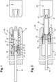
- Figures 1-4 show a contact arrangement 50 for a Pre-Insertion Resistor (PIR) according to a preferred embodiment of the invention. They show in particular details of the mechanical coupling between the control rod 20 and the movable contact 30 at consecutive stages of temporary connection with a PIR 60.
- PIR Pre-Insertion Resistor
- the contact arrangement 50 is provided in a circuit breaker installed in a Gas-Insulated Switchgear (GIS), the GIS circuit breaker comprising a double-motion interrupter and a parallel-connected PIR 60, i.e. a PIR arranged to be connected and disconnected in parallel to said interrupter. It comprises a control rod 20 operated by an actuator, and a movable contact 30 arranged to be moved by the control rod 20 into temporary electrical connection with a PIR 60 just before the interrupter is closed and disconnected from the PIR 60 just after.
- GIS Gas-Insulated Switchgear
- the movable contact 30 is slidably located in a tubular housing 10, and movable along an axis in a range between a start position and an end position.
- the movable contact 30 is tubular and comprises an external shoulder 36.
- the housing 10 has an internal shoulder 16.
- a helical spring 18 is located between the internal shoulder 16 and the external shoulder 36, such that the movement of the movable contact 30 towards the end position will compress the spring 18.
- the movable contact 30 also comprises an external step 38, arranged to abut against the internal shoulder 16 of the housing at the end position.
- the control rod 20 is located in the housing 10 and partly within the movable contact 30. It can move along the axis in a range allowing it to push the movable contact 30 between the start position and end position.
- the control rod 20 and the movable contact 30 are arranged such that they can be mechanically coupled to and decoupled from each other.
- the control rod 20 has a tulip 21, while the movable contact 30 has a latching ring 31.
- the tulip 21 and the latching ring 31 are the components that engage and disengage, to mechanically couple and decouple the control rod 20 and the movable contact 30.
- the tulip 21 is provided at the distal end of the control rod 20, aligned with the axis, and comprises a hub 22, a flange 23 located on the hub 22 and extending radially to the axis, and a plurality of fingers 24.
- the fingers 24 extend towards the PIR 60 and are attached at their base to the periphery of the flange 23 such that they are substantially parallel to, and surround, the axis.
- the tip of each finger 24 has a wedge-shaped formation 25, as seen in figure 1 , projecting radially outwards (away from the axis). These fingers 24 are resilient, and able to deflect inwards towards the axis.
- the flange 23 may also be made resilient to facilitate their deflection.
- the tulip 21 When the fingers 24 are undeflected, the tulip 21 has a first diameter (outer), and when the fingers 24 are deflected towards the axis, the tulip 21 has a second diameter. The tulip 21 therefore can be deformed from a first diameter to a second diameter smaller than the first.
- the latching ring 31 on the other hand is provided on the movable contact 30, near or at the proximal end. It is located such that it also surrounds the axis and is aligned with the tulip 21.
- the latching ring 31 has a wedge-shaped formation 35 projecting radially inwards (towards the axis). As it is generally rigid and not intended to deform, a single annular wedge-shaped formation 35 is sufficient, although it will be understood that the wedge-shape formation 35 may in cases be made up of several arc sections.
- the diameter (internal) of the latching ring 31 is such that it is smaller than the first diameter of the tulip 21, but larger than the second diameter.
- the control rod 20 When the movable contact 30 is to be brought into connection with the PIR 60, the control rod 20 is first moved towards the movable contact 30.
- the fingers 24 on the tulip 21 of the control rod 20 engage the latching ring 31 on the movable contact 30.
- the tulip 21 is at the first (larger) diameter at this point, and so the wedge-shape formations 25 on the fingers 24 abut the complementary wedge-shape formation 35 on the latching ring 31.
- This engagement is such that the control rod 20 is mechanically coupled to the movable contact 30, and able to move it in the axial direction towards the PIR 60.
- the control rod 20 then begins to push the movable contact 30 in the direction of the PIR 60.
- the resistance to the movement increases due to the helical spring 18 being compressed.
- the fingers 24 begin deflecting, although only minimally, maintaining the engagement with the latching ring 31, and thus the mechanical coupling between the control rod 20 and the movable contact 30.
- the end position shown in figure 2 , where the external step 38 of the movable contact 30 is in abutment engagement with the internal shoulder 16 of the housing 10 and thus the movable contact 30 prevented from moving further towards the PIR 60.
- the helical spring 18 is completely compressed, and a pin 37 provided at the distal end of the movable contact 30 is in complete connection with a terminal 67 on the PIR 60.
- the resistance to the axial movement exceeds a predetermined value, which is the engagement force between the tulip 21 and the latching ring 31, or more precisely, the axial component of the frictional force between the wedge-shaped formations 25 on the tulip 21 and the wedge-shaped formation 35 on the latching ring 31.
- a predetermined value which is the engagement force between the tulip 21 and the latching ring 31, or more precisely, the axial component of the frictional force between the wedge-shaped formations 25 on the tulip 21 and the wedge-shaped formation 35 on the latching ring 31.
- an elastomeric ring 28 may be secured with a fastener to the hub 22, between the tips of the fingers 24 and the axis. This helps to ensure that the fingers 24 of the tulip 21 are not damaged or permanently deformed when the latching ring 31 passes over.
- the latching ring 31 is thereby disengaged from the tulip 21, mechanically decoupling thus the movable contact 30 from the control rod 20.
- the movable contact 30 disconnects from the PIR 60 and returns back towards its start position, as can be seen in figure 4 , the latching ring 31 passing over the entire deformed tulip 21.
- the temporary connection with the PIR 60 typically lasts 8 to 20ms.
- the resilient fingers 24 of the tulip 24 revert to their undeflected state, restoring the tulip 21 to its first diameter.
- the control rod 20 however remains stationary, located now deeper within the returned movable contact 30.
- the actuator merely retracts the control rod 20 until the tulip 21 passes back through the latching ring 31, wherein it is returned to a position where it can recouple to the movable contact 30 (as shown in figure 1 ).
- the complementary wedge-shaped formations 25, 35 on the latching ring 31 and tulip 21 are shaped such that it is easier to pull the tulip 21 back through the latching ring 31 compared to pushing it through.
- the angle on the sides of the wedge-shaped formations 25, 35 that engage during mechanical coupling is more inclined, making it more difficult for the wedge-shaped formations 25, 35 to slide over one another, while the angle on the reverse sides is less inclined, allowing them to slide over one another more easily.
- the range of the control rod 20 is ideally slightly larger than that of the movable contact 30, so as to be able to push the movable contact 30 within its range.
- the tulip 21 and latching ring 31 are preferably made of stainless steel, although other materials can be envisaged.
- the elastomeric ring 28 is preferably made of EPDM rubber, although other materials can also be envisaged.
- the contact arrangement 50 for PIR of the present invention represents a significant improvement over known contact arrangements, the tulip 21 and latching ring 31 being far better suited to mechanically coupling and decoupling the control rod 20 and the movable contact 30.
- the fingers 24 of the tulip 21 experience minimal angular deflection, owing to their length being much greater than what the tip of the finger 24 is displaced during deflection. This in turn implies that the stress experienced at the connection between the fingers 24 and the flange 23, or the hub 22, is also minimal.
- the wedge-shaped formations 25, 35 are particularly advantageous for engagement and disengagement between the tulip 21 and the latching ring 31. Consequently, the mechanical coupling is better adapted to withstand deformation.
- This contact arrangement 50 therefore possesses the necessary mechanical endurance and reliability to last an extended number of cycles, allowing thus a superior circuit breaker to be attained.
Claims (15)
- Agencement de contact (50) pour une résistance de pré-insertion (PIR) comprenant une tige de commande (20) et un contact mobile (30) agencés pour être déplacés le long d'un axe, contre la force d'un organe de sollicitation (18), en liaison provisoire avec une PIR (60), dans lequel la tige de commande (20) est apte à déplacer le contact mobile (30) lorsqu'elle est couplée mécaniquement à celui-ci, et dans lequel le contact mobile (30) est agencé pour se découpler de la tige de commande (20), et retourner sous l'effet de la force de l'organe de sollicitation (18), une fois que la résistance au déplacement dépasse une valeur prédéterminée, caractérisé en ce que la tige de commande (20) comprend une tulipe (21) avec une pluralité de doigts élastiques (24), et le contact mobile (30) comprend un anneau de verrouillage (31), la tulipe (21) présentant un premier diamètre auquel elle est apte à se mettre en prise avec l'anneau de verrouillage (31) pour coupler mécaniquement la tige de commande (20) au contact mobile (30), les doigts (24) étant agencés pour être déviés vers l'intérieur de sorte que la tulipe (21) soit déformée en un second diamètre, dans lequel l'anneau de verrouillage (31) est apte à passer sur la tulipe (21) pour découpler le contact mobile (30) de la tige de commande (20).
- Agencement de contact selon la revendication 1, caractérisé en ce que la tulipe (21) comprend en outre un moyeu (22) et une bride (23) située sur le moyeu (22), la pluralité de doigts élastiques (24) étant attachés sur la périphérie de la bride (23) et s'étendant parallèlement à, et entourant, l'axe, et agencés pour être déviés vers l'axe.
- Agencement de contact selon la revendication 2, caractérisé en ce que la tulipe (21) comprend en outre un anneau élastomère (28) fixé au moyeu (22), situé entre les bouts des doigts (24) et l'axe.
- Agencement de contact selon la revendication 2 ou 3, caractérisé en ce que la tulipe (21) comprend des formations cunéiformes saillantes vers l'extérieur (25) aux bouts de la pluralité de doigts (24), les formations cunéiformes (25) étant agencées pour se mettre en prise avec l'anneau de verrouillage (31).
- Agencement de contact selon la revendication 4, caractérisé en ce que l'anneau de verrouillage (31) comporte une formation cunéiforme saillante vers l'intérieur (35) agencée pour être mise en prise par les formations cunéiformes (25) de la pluralité de doigts (24).
- Agencement de contact selon une quelconque revendication précédente, caractérisé en ce que le contact mobile (30) comporte un épaulement externe (36) et est agencé pour se déplacer dans un logement (10) avec un épaulement interne (16), l'organe de sollicitation (18) étant prévu entre l'épaulement externe (36) et l'épaulement interne (16).
- Agencement de contact selon la revendication 6, caractérisé en ce que le contact mobile (30) comprend en outre un pas externe (38).
- Agencement de contact selon la revendication 6 ou 7, caractérisé en ce que la quantité prédéterminée de la résistance au déplacement qui est dépassée est déterminée par la compression de l'organe de sollicitation (18), ou par le moment auquel le pas externe (38) du contact mobile (30) vient en butée contre l'épaulement interne (16) du logement (10).
- Agencement de contact selon une quelconque revendication précédente, caractérisé en ce que l'organe de sollicitation (18) est un ressort hélicoïdal.
- Agencement de contact selon une quelconque revendication précédente, caractérisé en ce que la tulipe (21) et l'anneau de verrouillage (31) sont constitués principalement d'acier inoxydable.
- Disjoncteur comportant un interrupteur et une PIR reliée en parallèle, le disjoncteur comprenant en outre un agencement de contact (50) selon une quelconque revendication précédente pour se relier à la PIR (60).
- Disjoncteur selon la revendication 11, caractérisé en ce que l'interrupteur est un interrupteur à double mouvement.
- Procédé de liaison provisoire d'un contact mobile (30) à une résistance de pré-insertion (PIR), le procédé comprenant la fourniture d'une tige de commande (20) comprenant une tulipe (21) avec une pluralité de doigts élastiques (24), la fourniture d'un contact mobile (30) comprenant un anneau de verrouillage (31), la mise en prise de l'anneau de verrouillage (31) avec la tulipe (21) à un premier diamètre pour coupler mécaniquement la tige de commande (20) au contact mobile (30), le déplacement du contact mobile (30) le long d'un axe, contre une force de sollicitation, en liaison provisoire avec une PIR (60) et, lorsque la résistance au déplacement dépasse une valeur prédéterminée, la déformation de la tulipe (21) du premier diamètre en un second diamètre en déviant ses doigts (24) vers l'intérieur et en faisant passer l'anneau de verrouillage (31) sur la tulipe (21) pour découpler le contact mobile (30) de la tige de commande (20), et le retour du contact mobile (30) sous l'effet de la force de sollicitation.
- Procédé selon la revendication 13, comprenant la mise en prise d'une formation cunéiforme saillante vers l'intérieur (35) sur l'anneau de verrouillage (31) avec des formations cunéiformes saillantes vers l'extérieur (25) aux bouts de la pluralité de doigts (24).
- Procédé selon la revendication 13 ou 14, comprenant la détermination de la valeur prédéterminée de la résistance au déplacement par la compression d'un organe de sollicitation (18) ou par la mise en butée du contact mobile (30) contre un logement (10) du contact mobile (30).
Priority Applications (2)
| Application Number | Priority Date | Filing Date | Title |
|---|---|---|---|
| EP19178265.5A EP3748658B1 (fr) | 2019-06-04 | 2019-06-04 | Agencement de contacts pour résistance de pré-insertion |
| US16/893,031 US11127550B2 (en) | 2019-06-04 | 2020-06-04 | Contact arrangement for pre-insertion resistor |
Applications Claiming Priority (1)
| Application Number | Priority Date | Filing Date | Title |
|---|---|---|---|
| EP19178265.5A EP3748658B1 (fr) | 2019-06-04 | 2019-06-04 | Agencement de contacts pour résistance de pré-insertion |
Publications (2)
| Publication Number | Publication Date |
|---|---|
| EP3748658A1 EP3748658A1 (fr) | 2020-12-09 |
| EP3748658B1 true EP3748658B1 (fr) | 2022-03-23 |
Family
ID=66770259
Family Applications (1)
| Application Number | Title | Priority Date | Filing Date |
|---|---|---|---|
| EP19178265.5A Active EP3748658B1 (fr) | 2019-06-04 | 2019-06-04 | Agencement de contacts pour résistance de pré-insertion |
Country Status (2)
| Country | Link |
|---|---|
| US (1) | US11127550B2 (fr) |
| EP (1) | EP3748658B1 (fr) |
Family Cites Families (10)
| Publication number | Priority date | Publication date | Assignee | Title |
|---|---|---|---|---|
| US4324959A (en) * | 1978-10-16 | 1982-04-13 | S&C Electric Company | Pre-insertion resistor mechanism for a circuit interrupting device |
| FR2553926B1 (fr) * | 1983-10-24 | 1986-08-01 | Merlin Gerin | Disjoncteur haute tension a resistances de fermeture |
| US5245145A (en) * | 1991-07-23 | 1993-09-14 | Abb Power T&D Company Inc. | Modular closing resistor |
| DE19547098A1 (de) * | 1995-12-16 | 1997-06-19 | Asea Brown Boveri | Leistungsschalter mit einem Einschaltwiderstand |
| FR2744283B1 (fr) * | 1996-01-31 | 1998-02-27 | Gec Alsthom T & D Sa | Disjoncteur a haute tension a resistance inseree a la fermeture |
| FR2748597B1 (fr) * | 1996-05-13 | 1998-06-12 | Gec Alsthom T & D Sa | Disjoncteur a haute tension avec insertion de resistance a la fermeture |
| US7078643B2 (en) * | 2003-12-15 | 2006-07-18 | Rostron Joseph R | Capacitor switch with internal retracting impedance contactor |
| CN101855694B (zh) * | 2007-09-10 | 2014-04-23 | Abb技术有限公司 | 具有用于接入合闸电阻的开关的高压功率开关 |
| FR2957451A1 (fr) | 2010-03-09 | 2011-09-16 | Areva T & D Sas | Interrupteur electrique haute tension avec retour sur fermeture et dispositif d'insertion d'une resistance |
| FR3016470B1 (fr) * | 2014-01-14 | 2016-02-26 | Alstom Technology Ltd | Sectionneur a detection de defaillance d'un ressort d'acceleration d'un contact d'arc |
-
2019
- 2019-06-04 EP EP19178265.5A patent/EP3748658B1/fr active Active
-
2020
- 2020-06-04 US US16/893,031 patent/US11127550B2/en active Active
Also Published As
| Publication number | Publication date |
|---|---|
| US11127550B2 (en) | 2021-09-21 |
| EP3748658A1 (fr) | 2020-12-09 |
| US20200388454A1 (en) | 2020-12-10 |
Similar Documents
| Publication | Publication Date | Title |
|---|---|---|
| US20130008873A1 (en) | Electrical high-voltage on-load disconnector and method for opening the same | |
| KR101313375B1 (ko) | 고전압 스위치를 위한 플렉서블 밀봉 | |
| CN104851757B (zh) | 三重稳定挠曲机构 | |
| US9263199B2 (en) | Electrical contact arrangement and air insulated medium voltage circuit breaker including the electrical contact arrangement | |
| US7902478B2 (en) | Switching chamber for a gas-insulated high-voltage switch | |
| EP3748658B1 (fr) | Agencement de contacts pour résistance de pré-insertion | |
| US20100012624A1 (en) | High-Voltage Disconnecting Circuit Breaker And Method Of Operating The Same | |
| US5359161A (en) | Non-linear spring for circuit interrupters | |
| CN111448635A (zh) | 真空开关管 | |
| WO2014076040A1 (fr) | Système de contact | |
| CN111989757B (zh) | 中央开断开关中用于母线传输切换的弹簧加载的辅助触头系统 | |
| US9543087B2 (en) | Contact system | |
| CN102779702A (zh) | 一种具有温度保护功能的气体绝缘式堵头 | |
| US8952285B2 (en) | Medium and high-voltage electric switch with return on closure and an insertion device for inserting a resistance | |
| US5302784A (en) | Circuit breaker inertia contact assembly for resistance insertion during opening and closing operations | |
| KR20200001928U (ko) | 가스 절연 차단기 | |
| KR102346992B1 (ko) | 스프링 유닛 및 디버터 스위치 | |
| KR20140097165A (ko) | 전기 아크 형성을 제한하기 위한 수단을 포함하는 전기 기구 | |
| CN115346824A (zh) | 三位置隔离开关 | |
| JPS5857227A (ja) | 断路器 |
Legal Events
| Date | Code | Title | Description |
|---|---|---|---|
| PUAI | Public reference made under article 153(3) epc to a published international application that has entered the european phase |
Free format text: ORIGINAL CODE: 0009012 |
|
| STAA | Information on the status of an ep patent application or granted ep patent |
Free format text: STATUS: THE APPLICATION HAS BEEN PUBLISHED |
|
| AK | Designated contracting states |
Kind code of ref document: A1 Designated state(s): AL AT BE BG CH CY CZ DE DK EE ES FI FR GB GR HR HU IE IS IT LI LT LU LV MC MK MT NL NO PL PT RO RS SE SI SK SM TR |
|
| AX | Request for extension of the european patent |
Extension state: BA ME |
|
| STAA | Information on the status of an ep patent application or granted ep patent |
Free format text: STATUS: REQUEST FOR EXAMINATION WAS MADE |
|
| 17P | Request for examination filed |
Effective date: 20210607 |
|
| RBV | Designated contracting states (corrected) |
Designated state(s): AL AT BE BG CH CY CZ DE DK EE ES FI FR GB GR HR HU IE IS IT LI LT LU LV MC MK MT NL NO PL PT RO RS SE SI SK SM TR |
|
| GRAP | Despatch of communication of intention to grant a patent |
Free format text: ORIGINAL CODE: EPIDOSNIGR1 |
|
| STAA | Information on the status of an ep patent application or granted ep patent |
Free format text: STATUS: GRANT OF PATENT IS INTENDED |
|
| RIC1 | Information provided on ipc code assigned before grant |
Ipc: H01H 33/16 20060101ALI20210930BHEP Ipc: H01H 33/12 20060101ALI20210930BHEP Ipc: H01H 7/12 20060101AFI20210930BHEP |
|
| INTG | Intention to grant announced |
Effective date: 20211014 |
|
| GRAS | Grant fee paid |
Free format text: ORIGINAL CODE: EPIDOSNIGR3 |
|
| GRAA | (expected) grant |
Free format text: ORIGINAL CODE: 0009210 |
|
| STAA | Information on the status of an ep patent application or granted ep patent |
Free format text: STATUS: THE PATENT HAS BEEN GRANTED |
|
| AK | Designated contracting states |
Kind code of ref document: B1 Designated state(s): AL AT BE BG CH CY CZ DE DK EE ES FI FR GB GR HR HU IE IS IT LI LT LU LV MC MK MT NL NO PL PT RO RS SE SI SK SM TR |
|
| REG | Reference to a national code |
Ref country code: GB Ref legal event code: FG4D |
|
| REG | Reference to a national code |
Ref country code: CH Ref legal event code: EP |
|
| REG | Reference to a national code |
Ref country code: IE Ref legal event code: FG4D |
|
| REG | Reference to a national code |
Ref country code: DE Ref legal event code: R096 Ref document number: 602019012729 Country of ref document: DE |
|
| REG | Reference to a national code |
Ref country code: AT Ref legal event code: REF Ref document number: 1478028 Country of ref document: AT Kind code of ref document: T Effective date: 20220415 |
|
| REG | Reference to a national code |
Ref country code: SE Ref legal event code: TRGR |
|
| REG | Reference to a national code |
Ref country code: LT Ref legal event code: MG9D |
|
| REG | Reference to a national code |
Ref country code: NL Ref legal event code: MP Effective date: 20220323 |
|
| PG25 | Lapsed in a contracting state [announced via postgrant information from national office to epo] |
Ref country code: RS Free format text: LAPSE BECAUSE OF FAILURE TO SUBMIT A TRANSLATION OF THE DESCRIPTION OR TO PAY THE FEE WITHIN THE PRESCRIBED TIME-LIMIT Effective date: 20220323 Ref country code: NO Free format text: LAPSE BECAUSE OF FAILURE TO SUBMIT A TRANSLATION OF THE DESCRIPTION OR TO PAY THE FEE WITHIN THE PRESCRIBED TIME-LIMIT Effective date: 20220623 Ref country code: LT Free format text: LAPSE BECAUSE OF FAILURE TO SUBMIT A TRANSLATION OF THE DESCRIPTION OR TO PAY THE FEE WITHIN THE PRESCRIBED TIME-LIMIT Effective date: 20220323 Ref country code: HR Free format text: LAPSE BECAUSE OF FAILURE TO SUBMIT A TRANSLATION OF THE DESCRIPTION OR TO PAY THE FEE WITHIN THE PRESCRIBED TIME-LIMIT Effective date: 20220323 Ref country code: BG Free format text: LAPSE BECAUSE OF FAILURE TO SUBMIT A TRANSLATION OF THE DESCRIPTION OR TO PAY THE FEE WITHIN THE PRESCRIBED TIME-LIMIT Effective date: 20220623 |
|
| REG | Reference to a national code |
Ref country code: AT Ref legal event code: MK05 Ref document number: 1478028 Country of ref document: AT Kind code of ref document: T Effective date: 20220323 |
|
| PG25 | Lapsed in a contracting state [announced via postgrant information from national office to epo] |
Ref country code: LV Free format text: LAPSE BECAUSE OF FAILURE TO SUBMIT A TRANSLATION OF THE DESCRIPTION OR TO PAY THE FEE WITHIN THE PRESCRIBED TIME-LIMIT Effective date: 20220323 Ref country code: GR Free format text: LAPSE BECAUSE OF FAILURE TO SUBMIT A TRANSLATION OF THE DESCRIPTION OR TO PAY THE FEE WITHIN THE PRESCRIBED TIME-LIMIT Effective date: 20220624 Ref country code: FI Free format text: LAPSE BECAUSE OF FAILURE TO SUBMIT A TRANSLATION OF THE DESCRIPTION OR TO PAY THE FEE WITHIN THE PRESCRIBED TIME-LIMIT Effective date: 20220323 |
|
| PG25 | Lapsed in a contracting state [announced via postgrant information from national office to epo] |
Ref country code: NL Free format text: LAPSE BECAUSE OF FAILURE TO SUBMIT A TRANSLATION OF THE DESCRIPTION OR TO PAY THE FEE WITHIN THE PRESCRIBED TIME-LIMIT Effective date: 20220323 |
|
| PG25 | Lapsed in a contracting state [announced via postgrant information from national office to epo] |
Ref country code: SM Free format text: LAPSE BECAUSE OF FAILURE TO SUBMIT A TRANSLATION OF THE DESCRIPTION OR TO PAY THE FEE WITHIN THE PRESCRIBED TIME-LIMIT Effective date: 20220323 Ref country code: SK Free format text: LAPSE BECAUSE OF FAILURE TO SUBMIT A TRANSLATION OF THE DESCRIPTION OR TO PAY THE FEE WITHIN THE PRESCRIBED TIME-LIMIT Effective date: 20220323 Ref country code: RO Free format text: LAPSE BECAUSE OF FAILURE TO SUBMIT A TRANSLATION OF THE DESCRIPTION OR TO PAY THE FEE WITHIN THE PRESCRIBED TIME-LIMIT Effective date: 20220323 Ref country code: PT Free format text: LAPSE BECAUSE OF FAILURE TO SUBMIT A TRANSLATION OF THE DESCRIPTION OR TO PAY THE FEE WITHIN THE PRESCRIBED TIME-LIMIT Effective date: 20220725 Ref country code: ES Free format text: LAPSE BECAUSE OF FAILURE TO SUBMIT A TRANSLATION OF THE DESCRIPTION OR TO PAY THE FEE WITHIN THE PRESCRIBED TIME-LIMIT Effective date: 20220323 Ref country code: EE Free format text: LAPSE BECAUSE OF FAILURE TO SUBMIT A TRANSLATION OF THE DESCRIPTION OR TO PAY THE FEE WITHIN THE PRESCRIBED TIME-LIMIT Effective date: 20220323 Ref country code: CZ Free format text: LAPSE BECAUSE OF FAILURE TO SUBMIT A TRANSLATION OF THE DESCRIPTION OR TO PAY THE FEE WITHIN THE PRESCRIBED TIME-LIMIT Effective date: 20220323 Ref country code: AT Free format text: LAPSE BECAUSE OF FAILURE TO SUBMIT A TRANSLATION OF THE DESCRIPTION OR TO PAY THE FEE WITHIN THE PRESCRIBED TIME-LIMIT Effective date: 20220323 |
|
| PG25 | Lapsed in a contracting state [announced via postgrant information from national office to epo] |
Ref country code: PL Free format text: LAPSE BECAUSE OF FAILURE TO SUBMIT A TRANSLATION OF THE DESCRIPTION OR TO PAY THE FEE WITHIN THE PRESCRIBED TIME-LIMIT Effective date: 20220323 Ref country code: IS Free format text: LAPSE BECAUSE OF FAILURE TO SUBMIT A TRANSLATION OF THE DESCRIPTION OR TO PAY THE FEE WITHIN THE PRESCRIBED TIME-LIMIT Effective date: 20220723 Ref country code: AL Free format text: LAPSE BECAUSE OF FAILURE TO SUBMIT A TRANSLATION OF THE DESCRIPTION OR TO PAY THE FEE WITHIN THE PRESCRIBED TIME-LIMIT Effective date: 20220323 |
|
| REG | Reference to a national code |
Ref country code: DE Ref legal event code: R097 Ref document number: 602019012729 Country of ref document: DE |
|
| PLBE | No opposition filed within time limit |
Free format text: ORIGINAL CODE: 0009261 |
|
| STAA | Information on the status of an ep patent application or granted ep patent |
Free format text: STATUS: NO OPPOSITION FILED WITHIN TIME LIMIT |
|
| PG25 | Lapsed in a contracting state [announced via postgrant information from national office to epo] |
Ref country code: MC Free format text: LAPSE BECAUSE OF FAILURE TO SUBMIT A TRANSLATION OF THE DESCRIPTION OR TO PAY THE FEE WITHIN THE PRESCRIBED TIME-LIMIT Effective date: 20220323 Ref country code: DK Free format text: LAPSE BECAUSE OF FAILURE TO SUBMIT A TRANSLATION OF THE DESCRIPTION OR TO PAY THE FEE WITHIN THE PRESCRIBED TIME-LIMIT Effective date: 20220323 |
|
| REG | Reference to a national code |
Ref country code: BE Ref legal event code: MM Effective date: 20220630 |
|
| 26N | No opposition filed |
Effective date: 20230102 |
|
| PG25 | Lapsed in a contracting state [announced via postgrant information from national office to epo] |
Ref country code: LU Free format text: LAPSE BECAUSE OF NON-PAYMENT OF DUE FEES Effective date: 20220604 Ref country code: IE Free format text: LAPSE BECAUSE OF NON-PAYMENT OF DUE FEES Effective date: 20220604 Ref country code: FR Free format text: LAPSE BECAUSE OF NON-PAYMENT OF DUE FEES Effective date: 20220630 |
|
| PG25 | Lapsed in a contracting state [announced via postgrant information from national office to epo] |
Ref country code: SI Free format text: LAPSE BECAUSE OF FAILURE TO SUBMIT A TRANSLATION OF THE DESCRIPTION OR TO PAY THE FEE WITHIN THE PRESCRIBED TIME-LIMIT Effective date: 20220323 Ref country code: BE Free format text: LAPSE BECAUSE OF NON-PAYMENT OF DUE FEES Effective date: 20220630 |
|
| P01 | Opt-out of the competence of the unified patent court (upc) registered |
Effective date: 20230522 |
|
| PG25 | Lapsed in a contracting state [announced via postgrant information from national office to epo] |
Ref country code: IT Free format text: LAPSE BECAUSE OF FAILURE TO SUBMIT A TRANSLATION OF THE DESCRIPTION OR TO PAY THE FEE WITHIN THE PRESCRIBED TIME-LIMIT Effective date: 20220323 |
|
| PGFP | Annual fee paid to national office [announced via postgrant information from national office to epo] |
Ref country code: DE Payment date: 20230523 Year of fee payment: 5 |
|
| PGFP | Annual fee paid to national office [announced via postgrant information from national office to epo] |
Ref country code: SE Payment date: 20230523 Year of fee payment: 5 |
|
| PGFP | Annual fee paid to national office [announced via postgrant information from national office to epo] |
Ref country code: CH Payment date: 20230702 Year of fee payment: 5 |
|
| GBPC | Gb: european patent ceased through non-payment of renewal fee |
Effective date: 20230604 |