EP3748399A1 - Systèmes et procédés permettant de déterminer la croissance de cellules par convection à partir de données de réflectivité de radar météorologique - Google Patents
Systèmes et procédés permettant de déterminer la croissance de cellules par convection à partir de données de réflectivité de radar météorologique Download PDFInfo
- Publication number
- EP3748399A1 EP3748399A1 EP20177624.2A EP20177624A EP3748399A1 EP 3748399 A1 EP3748399 A1 EP 3748399A1 EP 20177624 A EP20177624 A EP 20177624A EP 3748399 A1 EP3748399 A1 EP 3748399A1
- Authority
- EP
- European Patent Office
- Prior art keywords
- weather
- reflectivity
- values
- display
- vir
- Prior art date
- Legal status (The legal status is an assumption and is not a legal conclusion. Google has not performed a legal analysis and makes no representation as to the accuracy of the status listed.)
- Granted
Links
- 238000002310 reflectometry Methods 0.000 title claims abstract description 117
- 230000010261 cell growth Effects 0.000 title claims abstract description 45
- 238000000034 method Methods 0.000 title claims abstract description 32
- 239000000872 buffer Substances 0.000 claims abstract description 23
- 238000012545 processing Methods 0.000 claims description 38
- 230000004044 response Effects 0.000 claims description 2
- 239000007853 buffer solution Substances 0.000 description 13
- 230000006870 function Effects 0.000 description 10
- 238000007726 management method Methods 0.000 description 10
- 230000033001 locomotion Effects 0.000 description 9
- 230000012010 growth Effects 0.000 description 6
- 238000004040 coloring Methods 0.000 description 5
- 230000010354 integration Effects 0.000 description 4
- 238000004364 calculation method Methods 0.000 description 3
- 238000004891 communication Methods 0.000 description 3
- 238000001556 precipitation Methods 0.000 description 3
- 238000013459 approach Methods 0.000 description 2
- 230000003190 augmentative effect Effects 0.000 description 2
- 230000009087 cell motility Effects 0.000 description 2
- 238000013500 data storage Methods 0.000 description 2
- 238000010438 heat treatment Methods 0.000 description 2
- 239000007788 liquid Substances 0.000 description 2
- 230000003287 optical effect Effects 0.000 description 2
- XLYOFNOQVPJJNP-UHFFFAOYSA-N water Substances O XLYOFNOQVPJJNP-UHFFFAOYSA-N 0.000 description 2
- 206010000369 Accident Diseases 0.000 description 1
- 230000001149 cognitive effect Effects 0.000 description 1
- 239000003086 colorant Substances 0.000 description 1
- 238000009833 condensation Methods 0.000 description 1
- 230000005494 condensation Effects 0.000 description 1
- 238000001514 detection method Methods 0.000 description 1
- 238000011161 development Methods 0.000 description 1
- 238000010586 diagram Methods 0.000 description 1
- 230000000694 effects Effects 0.000 description 1
- 230000003993 interaction Effects 0.000 description 1
- 239000004973 liquid crystal related substance Substances 0.000 description 1
- 230000003137 locomotive effect Effects 0.000 description 1
- 238000005259 measurement Methods 0.000 description 1
- 238000012986 modification Methods 0.000 description 1
- 230000004048 modification Effects 0.000 description 1
- 230000000737 periodic effect Effects 0.000 description 1
- 230000008569 process Effects 0.000 description 1
- 239000004065 semiconductor Substances 0.000 description 1
- 230000035945 sensitivity Effects 0.000 description 1
- 239000010409 thin film Substances 0.000 description 1
- 230000007704 transition Effects 0.000 description 1
Images


Classifications
-
- G—PHYSICS
- G01—MEASURING; TESTING
- G01S—RADIO DIRECTION-FINDING; RADIO NAVIGATION; DETERMINING DISTANCE OR VELOCITY BY USE OF RADIO WAVES; LOCATING OR PRESENCE-DETECTING BY USE OF THE REFLECTION OR RERADIATION OF RADIO WAVES; ANALOGOUS ARRANGEMENTS USING OTHER WAVES
- G01S13/00—Systems using the reflection or reradiation of radio waves, e.g. radar systems; Analogous systems using reflection or reradiation of waves whose nature or wavelength is irrelevant or unspecified
- G01S13/88—Radar or analogous systems specially adapted for specific applications
- G01S13/95—Radar or analogous systems specially adapted for specific applications for meteorological use
- G01S13/953—Radar or analogous systems specially adapted for specific applications for meteorological use mounted on aircraft
-
- G—PHYSICS
- G01—MEASURING; TESTING
- G01S—RADIO DIRECTION-FINDING; RADIO NAVIGATION; DETERMINING DISTANCE OR VELOCITY BY USE OF RADIO WAVES; LOCATING OR PRESENCE-DETECTING BY USE OF THE REFLECTION OR RERADIATION OF RADIO WAVES; ANALOGOUS ARRANGEMENTS USING OTHER WAVES
- G01S13/00—Systems using the reflection or reradiation of radio waves, e.g. radar systems; Analogous systems using reflection or reradiation of waves whose nature or wavelength is irrelevant or unspecified
- G01S13/66—Radar-tracking systems; Analogous systems
- G01S13/72—Radar-tracking systems; Analogous systems for two-dimensional tracking, e.g. combination of angle and range tracking, track-while-scan radar
- G01S13/723—Radar-tracking systems; Analogous systems for two-dimensional tracking, e.g. combination of angle and range tracking, track-while-scan radar by using numerical data
-
- G—PHYSICS
- G01—MEASURING; TESTING
- G01S—RADIO DIRECTION-FINDING; RADIO NAVIGATION; DETERMINING DISTANCE OR VELOCITY BY USE OF RADIO WAVES; LOCATING OR PRESENCE-DETECTING BY USE OF THE REFLECTION OR RERADIATION OF RADIO WAVES; ANALOGOUS ARRANGEMENTS USING OTHER WAVES
- G01S7/00—Details of systems according to groups G01S13/00, G01S15/00, G01S17/00
- G01S7/02—Details of systems according to groups G01S13/00, G01S15/00, G01S17/00 of systems according to group G01S13/00
- G01S7/04—Display arrangements
- G01S7/06—Cathode-ray tube displays or other two dimensional or three-dimensional displays
- G01S7/22—Producing cursor lines and indicia by electronic means
-
- G—PHYSICS
- G01—MEASURING; TESTING
- G01S—RADIO DIRECTION-FINDING; RADIO NAVIGATION; DETERMINING DISTANCE OR VELOCITY BY USE OF RADIO WAVES; LOCATING OR PRESENCE-DETECTING BY USE OF THE REFLECTION OR RERADIATION OF RADIO WAVES; ANALOGOUS ARRANGEMENTS USING OTHER WAVES
- G01S7/00—Details of systems according to groups G01S13/00, G01S15/00, G01S17/00
- G01S7/02—Details of systems according to groups G01S13/00, G01S15/00, G01S17/00 of systems according to group G01S13/00
- G01S7/41—Details of systems according to groups G01S13/00, G01S15/00, G01S17/00 of systems according to group G01S13/00 using analysis of echo signal for target characterisation; Target signature; Target cross-section
- G01S7/411—Identification of targets based on measurements of radar reflectivity
-
- G—PHYSICS
- G01—MEASURING; TESTING
- G01S—RADIO DIRECTION-FINDING; RADIO NAVIGATION; DETERMINING DISTANCE OR VELOCITY BY USE OF RADIO WAVES; LOCATING OR PRESENCE-DETECTING BY USE OF THE REFLECTION OR RERADIATION OF RADIO WAVES; ANALOGOUS ARRANGEMENTS USING OTHER WAVES
- G01S7/00—Details of systems according to groups G01S13/00, G01S15/00, G01S17/00
- G01S7/02—Details of systems according to groups G01S13/00, G01S15/00, G01S17/00 of systems according to group G01S13/00
- G01S7/04—Display arrangements
-
- G—PHYSICS
- G01—MEASURING; TESTING
- G01W—METEOROLOGY
- G01W1/00—Meteorology
- G01W1/10—Devices for predicting weather conditions
-
- G—PHYSICS
- G01—MEASURING; TESTING
- G01W—METEOROLOGY
- G01W1/00—Meteorology
- G01W2001/003—Clear air turbulence detection or forecasting, e.g. for aircrafts
-
- G—PHYSICS
- G08—SIGNALLING
- G08G—TRAFFIC CONTROL SYSTEMS
- G08G5/00—Traffic control systems for aircraft, e.g. air-traffic control [ATC]
- G08G5/0017—Arrangements for implementing traffic-related aircraft activities, e.g. arrangements for generating, displaying, acquiring or managing traffic information
- G08G5/0021—Arrangements for implementing traffic-related aircraft activities, e.g. arrangements for generating, displaying, acquiring or managing traffic information located in the aircraft
-
- Y—GENERAL TAGGING OF NEW TECHNOLOGICAL DEVELOPMENTS; GENERAL TAGGING OF CROSS-SECTIONAL TECHNOLOGIES SPANNING OVER SEVERAL SECTIONS OF THE IPC; TECHNICAL SUBJECTS COVERED BY FORMER USPC CROSS-REFERENCE ART COLLECTIONS [XRACs] AND DIGESTS
- Y02—TECHNOLOGIES OR APPLICATIONS FOR MITIGATION OR ADAPTATION AGAINST CLIMATE CHANGE
- Y02A—TECHNOLOGIES FOR ADAPTATION TO CLIMATE CHANGE
- Y02A90/00—Technologies having an indirect contribution to adaptation to climate change
- Y02A90/10—Information and communication technologies [ICT] supporting adaptation to climate change, e.g. for weather forecasting or climate simulation
Definitions
- the present disclosure generally relates to weather detection using radar. More particularly, the present disclosure relates to systems and methods for determining convective cell growth from weather radar reflectivity data.
- Convective weather occurs when humid air is heated in an unstable atmosphere. As the air is heated, it rises. As it rises, it expands and cools, causing some of its moisture to condense as clouds. This condensation releases more heat into the air, causing it to rise further.
- the air In the unstable atmosphere, which has an adiabatic lapse rate exceeding standard, the air can remain warmer than its surrounding atmosphere for many thousands of feet vertically, causing cloud growth to propel upward at great rates of speed to a height of 40,000 - 50,000 feet or more.
- the initial heating of the air predominantly occurs when the sun heats the Earth, and the Earth radiates heat to the air immediately above it.
- convective cell growth may be of general interest to the public at large in terms of weather awareness, it is of particular interest to aviators.
- the rapid vertical growth of a convective cell is indicative of strong updrafts in the atmosphere, which at best would cause extreme turbulence to be encountered by an aircraft and at worst could be structurally catastrophic to the aircraft. Rapid horizontal growth could cause an inadvertent encounter with the cell when attempting to circumnavigate the aircraft.
- convective cells are associated with other dangers to aircraft, such as hail, which can cause damage to aircraft windscreens and turbine blades, and lightning, which can cause some localized damage.
- weather sources In the aforementioned context of aircraft, it is known to use various weather sources to obtain information regarding the location, size, and intensity of convective weather.
- One such source is the periodic reports disseminated by various weather services, such as the National Weather Service in the United States.
- Another source is a weather data-uplink, wherein data obtained from weather radar on the ground is collected and uplinked to an aircraft for display on a flight deck display of the aircraft.
- air traffic controllers often are provided with similar weather radar data, which can be relayed to the flight crew of the aircraft verbally.
- the primary and most up-to-date source of data regarding convective weather is an on-board weather radar system.
- This weather radar system usually located on a wing or in a nose-cone of the aircraft, emits radio waves forward of the aircraft within a defined horizontal angular range and a defined vertical angular range. These radio waves bounce off precipitation in the convective cell (e.g., rain, hail, snow) and return to the system in the form of a reflected signal.
- the reflected signal from all ranges of operation of the radar system are referred to as reflectivity data, and the reflectivity data is provided to the flight crew on a flight deck display to indicate the location and intensity of the precipitation in the convective cell.
- reflectivity data obtained from the on-board weather radar system has certain limitations.
- reflectivity data can be obtained from a range of altitudes for the geographic area in front of the aircraft
- the flight deck display may be limited graphically to showing the reflectivity of only a single altitude at one time.
- the vertical extent and development in terms of intensity at varying altitudes of a convective cell is often not immediately apparent to the flight crew.
- reflectivity data represents a snapshot in time, that is, of the time that the scan occurs.
- the flight deck display may lack any trend data in terms of cell growth, either in the horizontal or vertical directions.
- the flight crew is provided with information regarding the convective cell from perhaps 10 to 50 miles away as the aircraft approaches the cell, the present state of the art is that the flight crew is left with some uncertainty as to what the cell will look like later in time once the aircraft reaches the cell.
- a method for determining convective cell growth from weather radar reflectivity data includes, at a processing device, receiving first weather reflectivity values and receiving second weather reflectivity values at a point in time subsequent to receiving the first weather reflectivity values, storing the first and second weather reflectivity values in cells of a three-dimensional buffer, and, for each of the first and second weather reflectivity values, calculating a vertically-integrated reflectivity (VIR) value for a column of cells in the three-dimensional buffer, the column of cells being associated with a latitude/longitude position.
- VIR vertically-integrated reflectivity
- the method further includes, at the processing device, comparing the VIR value for the second weather reflectivity values against the VIR for the first weather reflectivity values to determine a difference in the VIR values. Still further, the method includes, at a display device coupled to the processing device, and if the difference in the sum of reflectivity values is greater than a threshold value, displaying a cell growth hazard indication at a weather display in an area of the weather display that corresponds to the latitude/longitude position.
- a system for determining convective cell growth from weather radar reflectivity data includes a display device coupled to receive display commands configured, in response to the display commands, to display one or more images, and a processing device coupled to the display device and configured to receive first weather reflectivity values and receiving second weather reflectivity values at a point in time subsequent to receiving the first weather reflectivity values, to store the first and second weather reflectivity values in cells of a three-dimensional buffer, and, for each of the first and second weather reflectivity values, to calculate a VIR value for a column of cells in the three-dimensional buffer, the column of cells being associated with a latitude/longitude position.
- the processing device is further configured to compare the VIR value for the second weather reflectivity values against the VIR for the first weather reflectivity values to determine a difference in the VIR values, and, if the difference in the VIR values is greater than a threshold value, supply display commands to the display device that cause the display device to display a cell growth hazard indication at a weather display in an area of the weather display that corresponds to the latitude/longitude position.
- Embodiments of the present disclosure may be described herein in terms of functional and/or logical block components and various processing steps. It should be appreciated that such block components may be realized by any number of hardware, software, and/or firmware components configured to perform the specified functions. For example, an embodiment of the present disclosure may employ various integrated circuit components, e.g ., memory elements, digital signal processing elements, logic elements, look-up tables, or the like, which may carry out a variety of functions under the control of one or more microprocessors or other control devices. In addition, those skilled in the art will appreciate that embodiments of the present disclosure may be practiced in conjunction with any number of systems, and that the systems described herein is merely exemplary embodiments of the present disclosure.
- the systems and methods operate by obtaining weather radar reflectivity data at various altitudes over a geographic area (for example a distance range in front of the aircraft).
- the reflectivity data is stored in a three-dimensional ("volumetric") buffer having a plurality of addresses that are indicative of the geographic location and altitude from which the reflectivity data is obtained.
- addresses that are disposed vertically with regard to one another may be summed or otherwise integrated, resulting in a vertically-integrated reflectivity (VIR) value for a particular geographic location. Multiple adjacent VIR values may define a convective cell.
- VIR vertically-integrated reflectivity
- the buffer is updated with new data over time, such data being compensated for movement of the aircraft, movement of the cell, and the curvature of the Earth.
- a comparison can be made between VIR values for a convective cell at a first time versus the VIR values at a second time to determine convective cell growth, if any. If the comparison indicates cell growth at a rate that exceeds a threshold, symbology may be displayed on a weather radar display in the flight deck of the aircraft so indicating. Such symbology may be integrated into a hierarchy of other convective cell symbology, such as lightning, hail, etc.
- FIG. 1 illustrates an aircraft 100 that includes a processing system 105, a flight management system (FMS) 110, a data buffer system 115, a position-determining system 120, a flight-deck display system 140, and a weather radar system 160.
- FMS flight management system
- Aircraft 100 may be any type of vehicle that is capable of travelling through the air ( i.e., without physical contact with terrain or water).
- aircraft 100 may be any type of airplane (regardless of size or propulsion means, ranging from large, turbine-powered commercial airplanes to small, electrically-powered drones), rotorcraft (helicopter, gyrocopter), lighter-than-air vessel (hot-air balloon, blimp), or glider, for example.
- Aircraft 100 may be "manned" in the conventional sense that the flight crew is present within the aircraft 100, or it may be manned remotely.
- Processing system 105 functions to receive and process data from the various systems of the aircraft 100 (e.g ., systems 110 - 160) during operation of the aircraft 100.
- the processing system 105 generally represents hardware, software, and/or firmware components configured to facilitate communications and/or interaction between the elements of the aircraft 100 and perform additional tasks and/or functions to support operation of the aircraft 100.
- the processing system 105 may be implemented or realized with a general-purpose processor, a content addressable memory, a digital signal processor, an application specific integrated circuit, a field programmable gate array, any suitable programmable logic device, discrete gate or transistor logic, processing core, discrete hardware components, or any combination thereof.
- the processing system 105 may also be implemented as a combination of computing devices, e.g., a plurality of processing cores, a combination of a digital signal processor and a microprocessor, a plurality of microprocessors, one or more microprocessors in conjunction with a digital signal processor core, or any other such configuration.
- the processing system 105 includes processing logic that may be configured to carry out the functions, techniques, and processing tasks associated with the operation of the aircraft 100, and in particular probabilistically determining the intended flight route of another aircraft.
- processing system 105 may be embodied with data processing functionalities utilizing any custom made or commercially available processor, a central processing unit (CPU), a graphics processing unit (GPU), an auxiliary processor among several processors, a semiconductor-based microprocessor (in the form of a microchip or chip set), a macroprocessor, any combination thereof, or generally any device for executing electronic instructions.
- CPU central processing unit
- GPU graphics processing unit
- auxiliary processor among several processors
- semiconductor-based microprocessor in the form of a microchip or chip set
- macroprocessor any combination thereof, or generally any device for executing electronic instructions.
- processing system 105 may be embodied with data storage functionalities utilizing volatile and/or nonvolatile storage such as read-only memory (ROM), random-access memory (RAM), and keep-alive memory (KAM), for example, and may be implemented using any of a number of known memory devices such as PROMs (programmable read-only memory), EPROMs (electrically PROM), EEPROMs (electrically erasable PROM), flash memory, or any other electric, magnetic, optical, or combination memory devices capable of storing data.
- PROMs programmable read-only memory
- EPROMs electrically PROM
- EEPROMs electrically erasable PROM
- flash memory or any other electric, magnetic, optical, or combination memory devices capable of storing data.
- Flight management system 110 provides the primary navigation, flight planning, and route determination and en route guidance for the aircraft 100.
- Flight management system 110 may provide navigation data associated with the aircraft's current position and flight direction (e.g., heading, course, track, etc. ) to processing system 105.
- the navigation data provided to processing system 105 may also include information about the aircraft's airspeed, ground speed, altitude ( e.g ., relative to sea level), pitch, and other important flight information if such information is desired.
- flight management system 110 may include any suitable position and direction determination devices that are capable of providing processing system 105 with at least an aircraft's current position (e.g., in latitudinal and longitudinal form), the real-time direction (heading, course, track, etc. ) of the aircraft in its flight path, and other important flight information (e.g., airspeed, altitude, pitch, attitude, etc. ) .
- Flight management system 110 and processing system 105 cooperate to guide and control aircraft 100 during all phases of operation, as well as to provide other systems of aircraft 100 with flight data generated or derived from flight management system 110.
- Data buffer system 115 functions to store weather reflectivity data from the weather radar system 160 in a plurality of three-dimensional addresses representative of geographical area and altitude.
- data buffer system may be embodied with data storage functionalities utilizing volatile and/or nonvolatile storage such as read-only memory (ROM), random-access memory (RAM), and keep-alive memory (KAM), for example, and may be implemented using any of a number of known memory devices such as PROMs (programmable read-only memory), EPROMs (electrically PROM), EEPROMs (electrically erasable PROM), flash memory, or any other electric, magnetic, optical, or combination memory devices capable of storing data.
- Data buffer system 115 may also be functional to store a time-stamp component along with the reflectivity data such that multiple reflectivity sets may be stored over time.
- Position-determining system 120 is operably connected with the processing system 105 and cooperates with the operation of flight management system 110. Position-determining system 120 is configured to obtain one or more navigational parameters associated with the operation of the aircraft 100.
- the position-determining system 120 may be realized as one or more of a global positioning system (GPS), inertial reference system (IRS), or a radio-based navigation system (e.g., VHF omni-directional radio range (VOR) or long-range aid to navigation (LORAN)), and it may include one or more navigational radios or other sensors suitably configured to support operation of the aircraft 100.
- GPS global positioning system
- IRS inertial reference system
- LORAN long-range aid to navigation
- the position-determining system 120 may also obtain and/or determine the heading of the aircraft 100 (i.e., the direction that aircraft 100 is traveling relative to some reference) using a magnet compass or a magnetometer, for example.
- the position-determining system 120 may also include a barometric altimeter such that the position of the aircraft 100 may be additionally determined with reference to a barometric altitude.
- the GPS may alternatively or additionally provide altitude information as part of the position-determining system 120.
- the position-determining system 120 is capable of obtaining and/or determining the instantaneous position and altitude of the aircraft 100, that is, the current location of the aircraft 100 ( e.g., the latitude and longitude) and the altitude and heading of the aircraft 100.
- the position-determining system 120 may provide this information to the processing system 105 and the flight management system 110 to support their operation, as described above.
- the flight-deck display system 140 may be embodied as an electronic display configured to graphically display weather information, flight information, traffic information, or other data associated with operation of the aircraft 100.
- display system 140 is operably coupled to the processing system 105, and may receive and graphically display information from the flight management system 110 (such as the flight plan), position-determining system 120 (such as the position, altitude, and heading of aircraft 100), and the weather radar system 160 (such as reflectivity data and convective cell growth symbology).
- the flight-deck display system 140 may be located within a flight-deck/cockpit of the aircraft 100.
- Flight-deck display system 140 may be embodied as one or more physical display devices of any type, and it may include a user interface that is adapted to allow a user (e.g., flight crew member) to interact with the display system 140 and more generally the FMS 110.
- display devices include various cathode ray tube (CRT) displays, and various flat panel displays such as various types of LCD (liquid crystal display) and TFT (thin film transistor) displays, panel mounted displays, and head-up display (HUD) projections.
- Non-limiting examples of such user interfaces include various keypads, touchpads, keyboards, mouses, touchscreens, joysticks, microphones, or other suitable devices adapted to receive input from a user.
- Flight-deck display system can also include other devices that are not physically integrated into the aircraft 100, such as an electronic flight bag (EFB) and the like.
- EFB electronic flight bag
- Weather radar system 160 is operably coupled with processing system 105, data buffer system 115, and flight-deck display system 140 to provide weather radar data to the flight crew of aircraft 100.
- the weather radar system 160 may be any suitable radar system that is operable to detect weather that is located within a detectable range from the aircraft 100, such as 100 miles or more.
- the weather radar system 160 is configured to sense sufficient weather radar return information in order to determine a volume of water in a given three-dimensional region of airspace.
- Weather radar system 160 may include an antenna that is operable to emit radar pulses and to receive radar returns, herein referred to as reflectivity data.
- Reflectivity data corresponds to that portion of a radar's signal reflected back to the radar by liquids (e.g., rain) and/or frozen droplets (e.g ., hail, sleet, and/or snow) residing in a weather object, such as a convective weather cell, or residing in areas proximate to a cloud or storm generating the liquids and/or frozen droplets.
- the weather radar system 160 is configured to calculate the distance of the weather object relative to the antenna based upon the length of time the transmitted signal pulse takes in the transition from the antenna to the object and back to the antenna. The relationship between distance and time is linear as the velocity of the signal is constant, approximately the speed of light in a vacuum.
- the antenna may be operable sweep in a back-and-forth motion, as well as in an up-and-down motion (tilt), such that the weather radar system 160 is able to scan an airspace region of interest in proximity to the aircraft.
- Such radar reflectivity data may be provided to data buffer system 115 for use in accordance with the presently-described embodiments, as well as processing system 105 for display on the flight-deck display system 140 along with appropriate overlaid symbology, as applicable.
- embodiments of the present disclosure employ the weather radar system 160 to obtain the three-dimensional distribution of radar reflectivity of weather for storage in the data buffer system 115.
- the embodiments may perform sums or other integrations of the stored reflectivity data in vertical columns of the data buffer system 115, and they may evaluate the integrations to obtain VIR values.
- an integration of reflectivity values stored in a column of data addresses in the three-dimensional data buffer system 115 is calculated.
- FIG. 2 is a conceptual perspective view of a portion of a three-dimensional data buffer 220 containing weather radar reflectivity data in accordance with exemplary embodiments of the present disclosure.
- Each data address or "cell" is representative of a three-dimensional, physical location in an environment 200 through which the aircraft 100 is flying.
- the data buffer 220 includes a plurality of such cells, e.g. cells 222 and 224.
- a vertical column of cells 226 is representative of a particular geographic location/area at all altitudes for which reflectivity data is available. Two or more adjacent vertical columns of reflectivity data may represent a convective weather cell.
- Variations of this embodiment may be augmented by employing other values of a to account for non-standard reflectivities obtained by the weather radar system 160, and other values of b may be used when reflectivity as a function of altitude (height) is desired.
- the data buffer system 115 is updated with new data over time, such data being compensated for movement of the aircraft, movement of the convective cell, and the curvature of the Earth.
- the amount of time between successive scans may generally depend on the time that it takes the system 160 to complete a scan, which varies from system to system.
- the compensation for aircraft movement (as well as Earth curvature, which is a known value) can be accomplished in coordination with the flight management system 110 and position-determining system 120 receiving indications of aircraft parameters such as speed, altitude, and geographic location during the course of the operation of the aircraft.
- movement of the convective cell may be accomplished in accordance with the algorithms described in commonly-assigned U.S.
- Patent 8,319,679 the contents of which are herein incorporated by reference in their entirety.
- the '679 patent generally describes a tracking function that provides a filtered convective cell position and velocity in the earth-fixed horizontal plane.
- the tracking function involves taking noisy measurements of cell position taken over time and estimating actual cell position and velocity. Thus, each successive store of new data over time is representative of the VIR values for a convective cell at successive points in time.
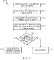
- step 302 at a first point in time, the weather radar system 160 in communication with the processing system 105 operates to obtain first reflectivity values for a volume of space in front of the aircraft. These first reflectivity values are then saved to the data buffer system 115 in its data buffer 220, wherein reflectivity values are saved in cells (222, 224) representative of the location from which particular reflectivity returns were received.
- the weather radar system 160 in communication with the processing system 105 operates to obtain second reflectivity values for a volume of space in front of the aircraft. These second reflectivity values are then saved to the data buffer system 115 in its data buffer 220 in the same manner as the first reflectivity values. It should be noted that the second reflectivity values may be corrected for aircraft movement, convective cell movement, and the curvature of the Earth, as described above, such that the second reflectivity values are representative of the same convective cell as the first reflectivity values, and not necessarily the exact same points in space.
- convective cell movement it should also be noted that, as described above, two or more adjacent columns, due to their reflectivity values, may be determined to constitute a convective cell, and thus the steps of method 300 that are described with regard to columns may be understood as applicable to the two or more adjacent columns defining a convective cell.
- the processing system 105 operating in conjunction with the data buffer system 115 calculates a sum of reflectivity values in each column of cells 226 in the three-dimensional data buffer 220. This calculation is performed for each column 226 and for both of the first and second stored reflectivity values. The result of these calculations is a VIR value for each column 226 for both of the first and second stored reflectivity values. Then, at step 308, for each column 226, the VIR value from the first reflectivity values may be compared against the VIR value for the same column 226 from the second reflectivity values, in order to determine a VIR difference. Where the VIR difference is an increase, there is thus an indication that the convective cell associated with the column(s) is growing in size, area, or intensity.
- the threshold value may be pre-programmed into the processing system 105 in advance, and the value may be determined based on flight crew preferences, operating location, and weather radar system 160 sensitivity/performance, among other considerations.
- convective cell growth symbology may be displayed to the flight crew using display system 140 as an overlay on the reflectivity imagery.
- the form of the symbology is not particularly limited in this disclosure; one illustrative example thereof is a "+" symbol, in an embodiment.
- the overlay may be located on the display at the location(s) of the reflectivity imagery where the convective cell growth is occurring. Exemplary displays with reflectivity imagery and convective cell growth symbology are provided and described below in connection with FIGS. 4 - 6 .
- the convective cell growth symbology is not displayed (whereas the reflectivity imagery and possibly other symbology, such as lightning or hail hazards, may still be displayed).
- the convective cell growth symbology displayed on the display system 140 as an overlay to the reflectivity imagery may be one of a plurality of symbology that includes others, such as lightning or hail.
- the convective cell growth symbology described herein may fall within a symbology hierarchy that includes the other symbology.
- the display of system 140 provided to the flight crew may become "cluttered” if all symbology were displayed at the same location, thus detracting from the ease of interpretation of the display, and possibly impairing flight crew situational awareness.
- the hierarchy described herein determines which symbology takes precedence of display when more than one symbology is applicable.
- the hierarch may be as follows, from lowest precedence to highest precedence: base reflectivity data; convective cell coloring in the reflectivity imagery; convective cell growth symbology overlay; lightning symbology overlay or hail symbology overlay.
- base reflectivity data convective cell coloring in the reflectivity imagery
- convective cell growth symbology overlay convective cell growth symbology overlay
- lightning symbology overlay or hail symbology overlay where reflectivity returns are received, but the values thereof are low enough such that convective weather is unlikely, only the base reflectivity returns are displayed using display system 140 (usually in various shades of green, yellow, and orange to indicated intensity).
- the coloring at the location of the suspected convective cell is changed to indicate the hazard (such as using magenta or red coloring, for contrast with the surrounding precipitation).
- the cell growth symbology e.g ., "+" may be overlaid on the convective cell imagery where the growth is occurring.
- FIG. 4 illustrates an exemplary long-range weather radar display 401 (as may be provided on display system 140) that includes a convective cell indicating cell growth above a predetermined threshold value 411. Given that the range of the scan is indicated at 320 miles (top left corner), the location of the convective cell is about 200 miles in front of the aircraft at a bearing of about 30 degrees east of the direction of travel of the aircraft. The convective cell growth symbology is shown as a "+" symbol.
- FIG. 4 illustrates an exemplary long-range weather radar display 401 (as may be provided on display system 140) that includes a convective cell indicating cell growth above a predetermined threshold value 411. Given that the range of the scan is indicated at 320 miles (top left corner), the location of the convective cell is about 200 miles in front of the aircraft at a bearing of about 30 degrees east of the direction of travel of the aircraft. The convective cell growth symbology is shown as a "+" symbol.
- FIG. 5 illustrates another exemplary long-range weather radar display 402 that includes at least one convective cell indicating cell growth 411 (about 170 miles directly in front of the aircraft), but further includes other convective cells that indicate hazards that take precedence in the hierarchy of symbology.
- FIG. 5 further includes a convective cell with indicated hail 412 (about 210 miles ahead of the aircraft at a bearing of about 10 degrees west of the direction of travel) and a convective cell with indicated lightning 413 (about 150 miles away from the aircraft at a bearing generally northeast of the direction of travel).
- FIG. 5 illustrates another exemplary long-range weather radar display 402 that includes at least one convective cell indicating cell growth 411 (about 170 miles directly in front of the aircraft), but further includes other convective cells that indicate hazards that take precedence in the hierarchy of symbology.
- FIG. 5 further includes a convective cell with indicated hail 412 (about 210 miles ahead of the aircraft at a bearing of about 10 degrees west of
- 6 provides a short-range (20 miles) weather radar display 403 that shows several convective cells indicating cell growth 411 immediately west and northwest of the aircraft, but also illustrates the difference in coloring to show convective weather (red/magenta in the inner portions of the cells, surrounded by non-convective outer rings of yellow/green; note that colors are simulated using various shading patterns in the Figures).
- convective weather red/magenta in the inner portions of the cells, surrounded by non-convective outer rings of yellow/green; note that colors are simulated using various shading patterns in the Figures.
- the present disclosure has provided several embodiments of systems and methods for determining convective cell growth from weather radar reflectivity data.
- the disclosed systems and methods beneficially provide symbology-based enhanced situational awareness to the flight crew regarding weather hazards that would otherwise require significant cognitive effort to determine and track over time as the aircraft approaches a convective weather system.
- the described embodiments are expected to positively impact aircraft operational safety and passenger comfort.
Applications Claiming Priority (1)
| Application Number | Priority Date | Filing Date | Title |
|---|---|---|---|
| US16/434,863 US11442164B2 (en) | 2019-06-07 | 2019-06-07 | Systems and methods for determining convective cell growth from weather radar reflectivity data |
Publications (2)
| Publication Number | Publication Date |
|---|---|
| EP3748399A1 true EP3748399A1 (fr) | 2020-12-09 |
| EP3748399B1 EP3748399B1 (fr) | 2023-03-01 |
Family
ID=70968871
Family Applications (1)
| Application Number | Title | Priority Date | Filing Date |
|---|---|---|---|
| EP20177624.2A Active EP3748399B1 (fr) | 2019-06-07 | 2020-05-29 | Systèmes et procédés permettant de déterminer la croissance de cellules par convection à partir de données de réflectivité de radar météorologique |
Country Status (2)
| Country | Link |
|---|---|
| US (1) | US11442164B2 (fr) |
| EP (1) | EP3748399B1 (fr) |
Cited By (2)
| Publication number | Priority date | Publication date | Assignee | Title |
|---|---|---|---|---|
| EP4067945A1 (fr) * | 2021-03-29 | 2022-10-05 | Rockwell Collins, Inc. | Interface homme-machine améliorée pour taux de croissance de tempête |
| EP4155772A1 (fr) * | 2021-09-23 | 2023-03-29 | Rockwell Collins, Inc. | Système et procédé de sélection et d'affichage d'image radar vertical à tranche azimutale priorisée |
Families Citing this family (4)
| Publication number | Priority date | Publication date | Assignee | Title |
|---|---|---|---|---|
| US20210263144A1 (en) * | 2020-02-26 | 2021-08-26 | RavenOPS, Inc. | Systems and methods of high speed scrubbing of airspace radar returns |
| US11787547B2 (en) * | 2021-02-22 | 2023-10-17 | Honeywell International Inc. | Icing detection using temperature data from an external data source |
| CN113296074B (zh) * | 2021-07-28 | 2022-02-22 | 成都远望探测技术有限公司 | 一种基于气象雷达多层cappi的光流法外推方法 |
| CN116430336B (zh) * | 2023-03-14 | 2023-10-24 | 中国气象局成都高原气象研究所 | 基于自适应阈值的对流单体识别方法 |
Citations (5)
| Publication number | Priority date | Publication date | Assignee | Title |
|---|---|---|---|---|
| US20110148692A1 (en) * | 2009-12-17 | 2011-06-23 | Honeywell International Inc. | Methods and systems for detection of hazard to aviation due to convective weather |
| US20120154209A1 (en) * | 2010-12-16 | 2012-06-21 | Honeywell International Inc. | Systems and methods for predicting locations of weather relative to an aircraft |
| EP3018492A1 (fr) * | 2014-11-06 | 2016-05-11 | Honeywell International Inc. | Radar météorologique à suppression de bande brillante |
| US9613269B2 (en) * | 2014-03-31 | 2017-04-04 | Honeywell International Inc. | Identifying and tracking convective weather cells |
| EP3330738A1 (fr) * | 2016-11-30 | 2018-06-06 | Honeywell International Inc. | Mappage de radar météorologique amélioré |
Family Cites Families (29)
| Publication number | Priority date | Publication date | Assignee | Title |
|---|---|---|---|---|
| US6266063B1 (en) | 1997-10-20 | 2001-07-24 | Baron Services, Inc. | Real-time three-dimensional weather display method and weathercast system |
| US7664601B2 (en) * | 1999-11-10 | 2010-02-16 | Honeywell International Inc. | Weather incident prediction |
| US6424288B1 (en) * | 2000-09-22 | 2002-07-23 | Rockwell Collins, Inc. | Multi-sweep method and system for detecting and displaying weather information on a weather radar system |
| US7515087B1 (en) | 2006-03-07 | 2009-04-07 | Rockwell Collins, Inc. | Weather radar system and method using data from a lightning sensor |
| US8902100B1 (en) * | 2008-03-07 | 2014-12-02 | Rockwell Collins, Inc. | System and method for turbulence detection |
| US6882302B1 (en) * | 2003-09-22 | 2005-04-19 | Rockwell Collins | Enhanced adaptive weather thresholds for identification of hazards system and method |
| US7109913B1 (en) * | 2004-05-04 | 2006-09-19 | Rockwell Collins, Inc. | Airborne weather radar system and radar display |
| US6879280B1 (en) | 2004-06-28 | 2005-04-12 | Rockwell Collins, Inc. | Vertical weather profile display system and method |
| US7242343B1 (en) * | 2004-09-15 | 2007-07-10 | Rockwell Collins, Inc. | Directed sequential hazard assessment weather radar |
| US7365673B2 (en) * | 2004-12-30 | 2008-04-29 | Honeywell International, Inc. | Compression and transmission of weather data |
| US7492305B1 (en) | 2006-09-27 | 2009-02-17 | Rockwell Collins, Inc. | Weather profile display system and method with uncertainty indication |
| US7486220B1 (en) | 2006-09-28 | 2009-02-03 | Rockwell Collins, Inc. | Storm top detection and prediction |
| US7656343B1 (en) | 2007-09-10 | 2010-02-02 | Rockwell Collins, Inc. | System and method for providing enhanced weather hazard alerting for aircraft |
| US8228227B2 (en) | 2010-12-02 | 2012-07-24 | Honeywell International Inc. | Systems and methods for improving relevant weather determination |
| US9411044B1 (en) | 2011-09-27 | 2016-08-09 | Rockwell Collins, Inc. | Auto updating of weather cell displays |
| US9019146B1 (en) | 2011-09-27 | 2015-04-28 | Rockwell Collins, Inc. | Aviation display depiction of weather threats |
| US9188700B2 (en) | 2012-03-08 | 2015-11-17 | Honeywell International Inc. | System and method to identify regions of airspace having ice crystals using an onboard weather radar system |
| CN104950186B (zh) * | 2014-03-31 | 2018-06-12 | 乌托巴斯洞察公司 | 雷电预测的方法和装置 |
| US10037124B2 (en) * | 2014-07-08 | 2018-07-31 | Honeywell International Inc. | Vertical profile display including weather icons |
| US9710218B2 (en) * | 2014-07-08 | 2017-07-18 | Honeywell International Inc. | Vertical profile display including hazard band indication |
| US10495783B2 (en) * | 2014-07-08 | 2019-12-03 | Honeywell International Inc. | Vertical profile display including weather blocks |
| KR101531246B1 (ko) * | 2014-11-27 | 2015-06-24 | 대한민국 | 기상 레이더 영상 내 대류 세포와 낙뢰 매칭 시스템 및 그의 제어 방법 |
| US10935693B2 (en) | 2015-03-18 | 2021-03-02 | Honeywell International Inc. | Prediction of ice crystal presence in a volume of airspace |
| US10139486B2 (en) | 2015-09-08 | 2018-11-27 | Korea Meteorological Administration | System for predicting path of convective cell and control method thereof |
| US10605912B1 (en) * | 2015-09-30 | 2020-03-31 | Rockwell Collins, Inc. | Storm top adaptive beam scan |
| US10302815B1 (en) * | 2015-10-01 | 2019-05-28 | Rockwell Collins, Inc. | System and method of integrating global convective weather |
| US10114381B2 (en) * | 2016-02-29 | 2018-10-30 | Garmin International, Inc. | Emergency autoload system |
| US10408972B1 (en) * | 2018-04-20 | 2019-09-10 | Adam Baker | System and method for lightning strike prediction and warning |
| US11203438B1 (en) * | 2018-12-13 | 2021-12-21 | Rockwell Collins, Inc. | System and method for deicing |
-
2019
- 2019-06-07 US US16/434,863 patent/US11442164B2/en active Active
-
2020
- 2020-05-29 EP EP20177624.2A patent/EP3748399B1/fr active Active
Patent Citations (7)
| Publication number | Priority date | Publication date | Assignee | Title |
|---|---|---|---|---|
| US20110148692A1 (en) * | 2009-12-17 | 2011-06-23 | Honeywell International Inc. | Methods and systems for detection of hazard to aviation due to convective weather |
| US8068050B2 (en) | 2009-12-17 | 2011-11-29 | Honeywell International Inc. | Methods and systems for detection of hazard to aviation due to convective weather |
| US20120154209A1 (en) * | 2010-12-16 | 2012-06-21 | Honeywell International Inc. | Systems and methods for predicting locations of weather relative to an aircraft |
| US8319679B2 (en) | 2010-12-16 | 2012-11-27 | Honeywell International Inc. | Systems and methods for predicting locations of weather relative to an aircraft |
| US9613269B2 (en) * | 2014-03-31 | 2017-04-04 | Honeywell International Inc. | Identifying and tracking convective weather cells |
| EP3018492A1 (fr) * | 2014-11-06 | 2016-05-11 | Honeywell International Inc. | Radar météorologique à suppression de bande brillante |
| EP3330738A1 (fr) * | 2016-11-30 | 2018-06-06 | Honeywell International Inc. | Mappage de radar météorologique amélioré |
Cited By (3)
| Publication number | Priority date | Publication date | Assignee | Title |
|---|---|---|---|---|
| EP4067945A1 (fr) * | 2021-03-29 | 2022-10-05 | Rockwell Collins, Inc. | Interface homme-machine améliorée pour taux de croissance de tempête |
| EP4155772A1 (fr) * | 2021-09-23 | 2023-03-29 | Rockwell Collins, Inc. | Système et procédé de sélection et d'affichage d'image radar vertical à tranche azimutale priorisée |
| US11852745B2 (en) | 2021-09-23 | 2023-12-26 | Rockwell Collins, Inc. | System and method to select and display prioritized azimuth slice vertical radar image |
Also Published As
| Publication number | Publication date |
|---|---|
| EP3748399B1 (fr) | 2023-03-01 |
| US20200386884A1 (en) | 2020-12-10 |
| US11442164B2 (en) | 2022-09-13 |
Similar Documents
| Publication | Publication Date | Title |
|---|---|---|
| EP3748399B1 (fr) | Systèmes et procédés permettant de déterminer la croissance de cellules par convection à partir de données de réflectivité de radar météorologique | |
| US8159369B1 (en) | Weather radar system and method | |
| US9535158B1 (en) | Weather radar system and method with fusion of multiple weather information sources | |
| US7492305B1 (en) | Weather profile display system and method with uncertainty indication | |
| US10175353B2 (en) | Enhancement of airborne weather radar performance using external weather data | |
| US8742952B1 (en) | Traffic awareness systems and methods | |
| US10037124B2 (en) | Vertical profile display including weather icons | |
| EP2264482B1 (fr) | Systèmes et procédés pour utiliser des informations NEXRAD pour vérifier les informations météorologiques de radars | |
| US7295901B1 (en) | System and method for indicating a position of an aircraft to a user | |
| US9869766B1 (en) | Enhancement of airborne weather radar performance using external weather data | |
| US9710218B2 (en) | Vertical profile display including hazard band indication | |
| US7109913B1 (en) | Airborne weather radar system and radar display | |
| US11181634B1 (en) | Systems and methods of intelligent weather sensing using deep learning convolutional neural networks | |
| US20090177343A1 (en) | System and method for selectable weather object display | |
| US9810770B1 (en) | Efficient retrieval of aviation data and weather over low bandwidth links | |
| US10495783B2 (en) | Vertical profile display including weather blocks | |
| US20040239550A1 (en) | Weather incident prediction | |
| US9689984B1 (en) | Weather radar system and method with latency compensation for data link weather information | |
| EP2799818A2 (fr) | Système et procédé pour afficher graphiquement les intempéries dans une vue en perspective | |
| US10605912B1 (en) | Storm top adaptive beam scan | |
| US9649935B2 (en) | Method and on-board system for viewing weather hazards | |
| US20210407306A1 (en) | Flight management system departure and arrival performance display based on weather data uplink | |
| US11790789B2 (en) | Gliding vertical margin guidance methods and systems | |
| EP4170385A1 (fr) | Prévision à court terme de radar météorologique pour affichages de cockpit en vol | |
| CN111798703A (zh) | 概率性地确定飞机预期飞行路线的系统和方法 |
Legal Events
| Date | Code | Title | Description |
|---|---|---|---|
| PUAI | Public reference made under article 153(3) epc to a published international application that has entered the european phase |
Free format text: ORIGINAL CODE: 0009012 |
|
| STAA | Information on the status of an ep patent application or granted ep patent |
Free format text: STATUS: THE APPLICATION HAS BEEN PUBLISHED |
|
| AK | Designated contracting states |
Kind code of ref document: A1 Designated state(s): AL AT BE BG CH CY CZ DE DK EE ES FI FR GB GR HR HU IE IS IT LI LT LU LV MC MK MT NL NO PL PT RO RS SE SI SK SM TR |
|
| AX | Request for extension of the european patent |
Extension state: BA ME |
|
| STAA | Information on the status of an ep patent application or granted ep patent |
Free format text: STATUS: REQUEST FOR EXAMINATION WAS MADE |
|
| 17P | Request for examination filed |
Effective date: 20210528 |
|
| RBV | Designated contracting states (corrected) |
Designated state(s): AL AT BE BG CH CY CZ DE DK EE ES FI FR GB GR HR HU IE IS IT LI LT LU LV MC MK MT NL NO PL PT RO RS SE SI SK SM TR |
|
| RAP3 | Party data changed (applicant data changed or rights of an application transferred) |
Owner name: HONEYWELL INTERNATIONAL INC. |
|
| GRAP | Despatch of communication of intention to grant a patent |
Free format text: ORIGINAL CODE: EPIDOSNIGR1 |
|
| STAA | Information on the status of an ep patent application or granted ep patent |
Free format text: STATUS: GRANT OF PATENT IS INTENDED |
|
| RIC1 | Information provided on ipc code assigned before grant |
Ipc: G01S 7/22 20060101ALI20220829BHEP Ipc: G01S 13/72 20060101ALI20220829BHEP Ipc: G01S 13/95 20060101AFI20220829BHEP |
|
| INTG | Intention to grant announced |
Effective date: 20220922 |
|
| GRAS | Grant fee paid |
Free format text: ORIGINAL CODE: EPIDOSNIGR3 |
|
| GRAA | (expected) grant |
Free format text: ORIGINAL CODE: 0009210 |
|
| STAA | Information on the status of an ep patent application or granted ep patent |
Free format text: STATUS: THE PATENT HAS BEEN GRANTED |
|
| AK | Designated contracting states |
Kind code of ref document: B1 Designated state(s): AL AT BE BG CH CY CZ DE DK EE ES FI FR GB GR HR HU IE IS IT LI LT LU LV MC MK MT NL NO PL PT RO RS SE SI SK SM TR |
|
| REG | Reference to a national code |
Ref country code: GB Ref legal event code: FG4D |
|
| REG | Reference to a national code |
Ref country code: CH Ref legal event code: EP Ref country code: AT Ref legal event code: REF Ref document number: 1551366 Country of ref document: AT Kind code of ref document: T Effective date: 20230315 |
|
| REG | Reference to a national code |
Ref country code: DE Ref legal event code: R096 Ref document number: 602020008398 Country of ref document: DE |
|
| REG | Reference to a national code |
Ref country code: IE Ref legal event code: FG4D |
|
| P01 | Opt-out of the competence of the unified patent court (upc) registered |
Effective date: 20230421 |
|
| REG | Reference to a national code |
Ref country code: LT Ref legal event code: MG9D |
|
| REG | Reference to a national code |
Ref country code: NL Ref legal event code: MP Effective date: 20230301 |
|
| PG25 | Lapsed in a contracting state [announced via postgrant information from national office to epo] |
Ref country code: RS Free format text: LAPSE BECAUSE OF FAILURE TO SUBMIT A TRANSLATION OF THE DESCRIPTION OR TO PAY THE FEE WITHIN THE PRESCRIBED TIME-LIMIT Effective date: 20230301 Ref country code: NO Free format text: LAPSE BECAUSE OF FAILURE TO SUBMIT A TRANSLATION OF THE DESCRIPTION OR TO PAY THE FEE WITHIN THE PRESCRIBED TIME-LIMIT Effective date: 20230601 Ref country code: LV Free format text: LAPSE BECAUSE OF FAILURE TO SUBMIT A TRANSLATION OF THE DESCRIPTION OR TO PAY THE FEE WITHIN THE PRESCRIBED TIME-LIMIT Effective date: 20230301 Ref country code: LT Free format text: LAPSE BECAUSE OF FAILURE TO SUBMIT A TRANSLATION OF THE DESCRIPTION OR TO PAY THE FEE WITHIN THE PRESCRIBED TIME-LIMIT Effective date: 20230301 Ref country code: HR Free format text: LAPSE BECAUSE OF FAILURE TO SUBMIT A TRANSLATION OF THE DESCRIPTION OR TO PAY THE FEE WITHIN THE PRESCRIBED TIME-LIMIT Effective date: 20230301 Ref country code: ES Free format text: LAPSE BECAUSE OF FAILURE TO SUBMIT A TRANSLATION OF THE DESCRIPTION OR TO PAY THE FEE WITHIN THE PRESCRIBED TIME-LIMIT Effective date: 20230301 |
|
| PGFP | Annual fee paid to national office [announced via postgrant information from national office to epo] |
Ref country code: FR Payment date: 20230523 Year of fee payment: 4 |
|
| REG | Reference to a national code |
Ref country code: AT Ref legal event code: MK05 Ref document number: 1551366 Country of ref document: AT Kind code of ref document: T Effective date: 20230301 |
|
| PG25 | Lapsed in a contracting state [announced via postgrant information from national office to epo] |
Ref country code: SE Free format text: LAPSE BECAUSE OF FAILURE TO SUBMIT A TRANSLATION OF THE DESCRIPTION OR TO PAY THE FEE WITHIN THE PRESCRIBED TIME-LIMIT Effective date: 20230301 Ref country code: PL Free format text: LAPSE BECAUSE OF FAILURE TO SUBMIT A TRANSLATION OF THE DESCRIPTION OR TO PAY THE FEE WITHIN THE PRESCRIBED TIME-LIMIT Effective date: 20230301 Ref country code: NL Free format text: LAPSE BECAUSE OF FAILURE TO SUBMIT A TRANSLATION OF THE DESCRIPTION OR TO PAY THE FEE WITHIN THE PRESCRIBED TIME-LIMIT Effective date: 20230301 Ref country code: GR Free format text: LAPSE BECAUSE OF FAILURE TO SUBMIT A TRANSLATION OF THE DESCRIPTION OR TO PAY THE FEE WITHIN THE PRESCRIBED TIME-LIMIT Effective date: 20230602 Ref country code: FI Free format text: LAPSE BECAUSE OF FAILURE TO SUBMIT A TRANSLATION OF THE DESCRIPTION OR TO PAY THE FEE WITHIN THE PRESCRIBED TIME-LIMIT Effective date: 20230301 |
|
| PG25 | Lapsed in a contracting state [announced via postgrant information from national office to epo] |
Ref country code: SM Free format text: LAPSE BECAUSE OF FAILURE TO SUBMIT A TRANSLATION OF THE DESCRIPTION OR TO PAY THE FEE WITHIN THE PRESCRIBED TIME-LIMIT Effective date: 20230301 Ref country code: RO Free format text: LAPSE BECAUSE OF FAILURE TO SUBMIT A TRANSLATION OF THE DESCRIPTION OR TO PAY THE FEE WITHIN THE PRESCRIBED TIME-LIMIT Effective date: 20230301 Ref country code: PT Free format text: LAPSE BECAUSE OF FAILURE TO SUBMIT A TRANSLATION OF THE DESCRIPTION OR TO PAY THE FEE WITHIN THE PRESCRIBED TIME-LIMIT Effective date: 20230703 Ref country code: EE Free format text: LAPSE BECAUSE OF FAILURE TO SUBMIT A TRANSLATION OF THE DESCRIPTION OR TO PAY THE FEE WITHIN THE PRESCRIBED TIME-LIMIT Effective date: 20230301 Ref country code: CZ Free format text: LAPSE BECAUSE OF FAILURE TO SUBMIT A TRANSLATION OF THE DESCRIPTION OR TO PAY THE FEE WITHIN THE PRESCRIBED TIME-LIMIT Effective date: 20230301 Ref country code: AT Free format text: LAPSE BECAUSE OF FAILURE TO SUBMIT A TRANSLATION OF THE DESCRIPTION OR TO PAY THE FEE WITHIN THE PRESCRIBED TIME-LIMIT Effective date: 20230301 |
|
| PG25 | Lapsed in a contracting state [announced via postgrant information from national office to epo] |
Ref country code: SK Free format text: LAPSE BECAUSE OF FAILURE TO SUBMIT A TRANSLATION OF THE DESCRIPTION OR TO PAY THE FEE WITHIN THE PRESCRIBED TIME-LIMIT Effective date: 20230301 Ref country code: IS Free format text: LAPSE BECAUSE OF FAILURE TO SUBMIT A TRANSLATION OF THE DESCRIPTION OR TO PAY THE FEE WITHIN THE PRESCRIBED TIME-LIMIT Effective date: 20230701 |
|
| REG | Reference to a national code |
Ref country code: DE Ref legal event code: R119 Ref document number: 602020008398 Country of ref document: DE |
|
| REG | Reference to a national code |
Ref country code: CH Ref legal event code: PL |
|
| PLBE | No opposition filed within time limit |
Free format text: ORIGINAL CODE: 0009261 |
|
| STAA | Information on the status of an ep patent application or granted ep patent |
Free format text: STATUS: NO OPPOSITION FILED WITHIN TIME LIMIT |
|
| PG25 | Lapsed in a contracting state [announced via postgrant information from national office to epo] |
Ref country code: MC Free format text: LAPSE BECAUSE OF FAILURE TO SUBMIT A TRANSLATION OF THE DESCRIPTION OR TO PAY THE FEE WITHIN THE PRESCRIBED TIME-LIMIT Effective date: 20230301 |
|
| REG | Reference to a national code |
Ref country code: BE Ref legal event code: MM Effective date: 20230531 |
|
| PG25 | Lapsed in a contracting state [announced via postgrant information from national office to epo] |
Ref country code: SI Free format text: LAPSE BECAUSE OF FAILURE TO SUBMIT A TRANSLATION OF THE DESCRIPTION OR TO PAY THE FEE WITHIN THE PRESCRIBED TIME-LIMIT Effective date: 20230301 Ref country code: MC Free format text: LAPSE BECAUSE OF FAILURE TO SUBMIT A TRANSLATION OF THE DESCRIPTION OR TO PAY THE FEE WITHIN THE PRESCRIBED TIME-LIMIT Effective date: 20230301 Ref country code: LU Free format text: LAPSE BECAUSE OF NON-PAYMENT OF DUE FEES Effective date: 20230529 Ref country code: LI Free format text: LAPSE BECAUSE OF NON-PAYMENT OF DUE FEES Effective date: 20230531 Ref country code: DK Free format text: LAPSE BECAUSE OF FAILURE TO SUBMIT A TRANSLATION OF THE DESCRIPTION OR TO PAY THE FEE WITHIN THE PRESCRIBED TIME-LIMIT Effective date: 20230301 Ref country code: CH Free format text: LAPSE BECAUSE OF NON-PAYMENT OF DUE FEES Effective date: 20230531 |
|
| 26N | No opposition filed |
Effective date: 20231204 |
|
| REG | Reference to a national code |
Ref country code: IE Ref legal event code: MM4A |
|
| PG25 | Lapsed in a contracting state [announced via postgrant information from national office to epo] |
Ref country code: IE Free format text: LAPSE BECAUSE OF NON-PAYMENT OF DUE FEES Effective date: 20230529 |