EP3748354A1 - Quick liquid exchange in liquid chromatography - Google Patents
Quick liquid exchange in liquid chromatography Download PDFInfo
- Publication number
- EP3748354A1 EP3748354A1 EP19178228.3A EP19178228A EP3748354A1 EP 3748354 A1 EP3748354 A1 EP 3748354A1 EP 19178228 A EP19178228 A EP 19178228A EP 3748354 A1 EP3748354 A1 EP 3748354A1
- Authority
- EP
- European Patent Office
- Prior art keywords
- pump head
- liquid
- pump
- exchange
- primary
- Prior art date
- Legal status (The legal status is an assumption and is not a legal conclusion. Google has not performed a legal analysis and makes no representation as to the accuracy of the status listed.)
- Granted
Links
Images




Classifications
-
- G—PHYSICS
- G01—MEASURING; TESTING
- G01N—INVESTIGATING OR ANALYSING MATERIALS BY DETERMINING THEIR CHEMICAL OR PHYSICAL PROPERTIES
- G01N30/00—Investigating or analysing materials by separation into components using adsorption, absorption or similar phenomena or using ion-exchange, e.g. chromatography or field flow fractionation
- G01N30/02—Column chromatography
-
- G—PHYSICS
- G01—MEASURING; TESTING
- G01N—INVESTIGATING OR ANALYSING MATERIALS BY DETERMINING THEIR CHEMICAL OR PHYSICAL PROPERTIES
- G01N30/00—Investigating or analysing materials by separation into components using adsorption, absorption or similar phenomena or using ion-exchange, e.g. chromatography or field flow fractionation
- G01N30/02—Column chromatography
- G01N30/26—Conditioning of the fluid carrier; Flow patterns
- G01N30/28—Control of physical parameters of the fluid carrier
- G01N30/32—Control of physical parameters of the fluid carrier of pressure or speed
-
- F—MECHANICAL ENGINEERING; LIGHTING; HEATING; WEAPONS; BLASTING
- F04—POSITIVE - DISPLACEMENT MACHINES FOR LIQUIDS; PUMPS FOR LIQUIDS OR ELASTIC FLUIDS
- F04B—POSITIVE-DISPLACEMENT MACHINES FOR LIQUIDS; PUMPS
- F04B49/00—Control, e.g. of pump delivery, or pump pressure of, or safety measures for, machines, pumps, or pumping installations, not otherwise provided for, or of interest apart from, groups F04B1/00 - F04B47/00
- F04B49/06—Control using electricity
- F04B49/065—Control using electricity and making use of computers
-
- F—MECHANICAL ENGINEERING; LIGHTING; HEATING; WEAPONS; BLASTING
- F04—POSITIVE - DISPLACEMENT MACHINES FOR LIQUIDS; PUMPS FOR LIQUIDS OR ELASTIC FLUIDS
- F04B—POSITIVE-DISPLACEMENT MACHINES FOR LIQUIDS; PUMPS
- F04B49/00—Control, e.g. of pump delivery, or pump pressure of, or safety measures for, machines, pumps, or pumping installations, not otherwise provided for, or of interest apart from, groups F04B1/00 - F04B47/00
- F04B49/08—Regulating by delivery pressure
-
- G—PHYSICS
- G01—MEASURING; TESTING
- G01N—INVESTIGATING OR ANALYSING MATERIALS BY DETERMINING THEIR CHEMICAL OR PHYSICAL PROPERTIES
- G01N30/00—Investigating or analysing materials by separation into components using adsorption, absorption or similar phenomena or using ion-exchange, e.g. chromatography or field flow fractionation
- G01N30/02—Column chromatography
- G01N30/04—Preparation or injection of sample to be analysed
- G01N30/16—Injection
-
- G—PHYSICS
- G01—MEASURING; TESTING
- G01N—INVESTIGATING OR ANALYSING MATERIALS BY DETERMINING THEIR CHEMICAL OR PHYSICAL PROPERTIES
- G01N30/00—Investigating or analysing materials by separation into components using adsorption, absorption or similar phenomena or using ion-exchange, e.g. chromatography or field flow fractionation
- G01N30/02—Column chromatography
- G01N30/26—Conditioning of the fluid carrier; Flow patterns
- G01N30/38—Flow patterns
- G01N30/46—Flow patterns using more than one column
-
- F—MECHANICAL ENGINEERING; LIGHTING; HEATING; WEAPONS; BLASTING
- F04—POSITIVE - DISPLACEMENT MACHINES FOR LIQUIDS; PUMPS FOR LIQUIDS OR ELASTIC FLUIDS
- F04B—POSITIVE-DISPLACEMENT MACHINES FOR LIQUIDS; PUMPS
- F04B2205/00—Fluid parameters
- F04B2205/05—Pressure after the pump outlet
-
- G—PHYSICS
- G01—MEASURING; TESTING
- G01N—INVESTIGATING OR ANALYSING MATERIALS BY DETERMINING THEIR CHEMICAL OR PHYSICAL PROPERTIES
- G01N30/00—Investigating or analysing materials by separation into components using adsorption, absorption or similar phenomena or using ion-exchange, e.g. chromatography or field flow fractionation
- G01N30/02—Column chromatography
- G01N2030/022—Column chromatography characterised by the kind of separation mechanism
- G01N2030/027—Liquid chromatography
-
- G—PHYSICS
- G01—MEASURING; TESTING
- G01N—INVESTIGATING OR ANALYSING MATERIALS BY DETERMINING THEIR CHEMICAL OR PHYSICAL PROPERTIES
- G01N30/00—Investigating or analysing materials by separation into components using adsorption, absorption or similar phenomena or using ion-exchange, e.g. chromatography or field flow fractionation
- G01N30/02—Column chromatography
- G01N30/26—Conditioning of the fluid carrier; Flow patterns
- G01N30/28—Control of physical parameters of the fluid carrier
- G01N30/32—Control of physical parameters of the fluid carrier of pressure or speed
- G01N2030/326—Control of physical parameters of the fluid carrier of pressure or speed pumps
-
- G—PHYSICS
- G01—MEASURING; TESTING
- G01N—INVESTIGATING OR ANALYSING MATERIALS BY DETERMINING THEIR CHEMICAL OR PHYSICAL PROPERTIES
- G01N30/00—Investigating or analysing materials by separation into components using adsorption, absorption or similar phenomena or using ion-exchange, e.g. chromatography or field flow fractionation
- G01N30/02—Column chromatography
- G01N30/26—Conditioning of the fluid carrier; Flow patterns
- G01N30/28—Control of physical parameters of the fluid carrier
- G01N30/34—Control of physical parameters of the fluid carrier of fluid composition, e.g. gradient
Definitions
- the present disclosure is related to a system and to a method for liquid exchange in liquid chromatography.
- kits may in part facilitate sample preparation that can be at least in part automated. Kits are however available only for a limited number of analytes of interest and the entire process from sample preparation, to separation and detection remains complex, requiring the attendance of highly trained laboratory personnel to run highly sophisticated instruments.
- U.S. Patent Application Pub. No. 2018/0292368 A1 describes a system and a method enabling automated random-access sample preparation and LC separation, thereby making use of LC coupled to mass spectrometry suitable for clinical diagnostics.
- solvent/eluent exchange in liquid chromatography is done by repeated filling of pump cylinders and subsequent expelling of the liquid. Due to the nature of pump action and to internal dead volumes, liquid exchange is a process of repeated dilution of the previously used liquid by the newly used liquid. This process is time consuming, requiring up to several minutes, and therefore represents a bottleneck if the goal is to achieve high-throughput random-access sample processing.
- liquid exchange is typically associated with a temporary loss of liquid pressure, which may reduce LC column lifetime and chromatographic performance.
- the embodiments of the present disclosure are not limited to specific advantages or functionality, it is noted that the present disclosure allows for a liquid chromatographic (LC) system and a method of exchanging a liquid in a liquid chromatographic system which enable quicker liquid exchange in liquid chromatography and therefore enable high-throughput random-access liquid chromatography, eventually coupled to mass spectrometry.
- LC liquid chromatographic
- Another advantage of the system and method herein disclosed is that a loss of liquid pressure during liquid exchange can be prevented, thereby extending LC column lifetime and improving chromatographic performance.
- the liquid chromatographic system of the present disclosure comprises a liquid chromatography pump comprising at least one pump head comprising a primary pump head and a secondary pump head, each comprising a syringe-like cylinder body having an inner wall surface and a plunger translatable through the cylinder body leaving an interspace between the inner wall surface and the plunger when the plunger is translated through the cylinder body, an upstream inlet valve configured to allow liquid into the cylinder body and a downstream outlet valve configured to allow liquid out of the cylinder body, the downstream outlet valve of the primary pump head being connected to the upstream inlet valve of the secondary pump head.
- the liquid chromatographic system further comprises at least one liquid-exchange pump connected either to the upstream inlet valve of the primary pump head or to the downstream outlet valve of the secondary pump head, the liquid exchange pump configured for exchanging a liquid present in the cylinder bodies of the primary and secondary pump heads with another liquid by purging through the interspaces left between the inner wall surfaces of the cylinder bodies and the plungers, respectively.
- Liquid chromatography or LC is an analytical process that subjects samples injected by a sample injector to chromatographic separation through a LC column in order for example to separate analytes of interest from matrix components, e.g., remaining matrix components after sample preparation that may still interfere with a subsequent detection, e.g., a mass spectrometry detection, and/or in order to separate analytes of interest from each other in order to enable their individual detection.
- a subsequent detection e.g., a mass spectrometry detection
- a "liquid chromatographic system or LC system” is an analytical apparatus or module or a unit in an analytical apparatus for carrying out liquid chromatography.
- the LC system may be embodied as a single channel or as a multi-channel system that may comprise one or a plurality of LC columns arranged in parallel and/or in series.
- the LC system may also comprise elements such as a sample injector, valves, liquid sources, fluidic connections and parts, e.g., for mixing liquids, degassing liquids, tempering liquids, and the like, one or more sensors, such as pressure sensors, temperature sensors and the like, and especially at least one LC pump.
- the list is not exhaustive.
- the LC system is an analytical module designed to prepare a sample for mass spectrometry and/or to transfer a prepared sample to a mass spectrometer, in particular for separating analytes of interest before detection by a mass spectrometer.
- the mass spectrometer may be set to scan a specific mass range.
- LC/MS data can be represented by adding up the ion current in the individual mass scans and plotting that "totaled" ion current as an intensity point against time. The resulting plot looks like an HPLC UV trace with analyte peaks.
- the LC system may otherwise comprise a detector of its own such as a UV detector.
- An "LC channel” is a fluidic line comprising at least one capillary tubing and/or LC column comprising a stationary phase selected according to the type of sample(s) and analytes and through which a mobile phase is pumped in order to trap and/or separate and elute and/or transfer analytes of interest under selected conditions, e.g., according to their polarity or log P value, size or affinity, as generally known.
- the at least one LC column in the at least one LC channel may be exchangeable.
- the LC system may comprise more LC columns than LC channels, where a plurality of LC columns may be interchangeably coupled to the same LC channel.
- Capillary tubing may be also used to bypass LC columns.
- LC column may refer to any of a column, a cartridge, a capillary and the like for performing separations of a chromatographic nature.
- Columns are typically packed or loaded with a stationary phase, through which a mobile phase is pumped in order to trap and/or separate and elute and/or transfer analytes of interest under selected conditions, e.g., according to their polarity or log P value, size or affinity, as generally known.
- This stationary phase can be particulate or beadlike or a porous monolith.
- the term “column” may also refer to capillaries which are not packed or loaded with a stationary phase but rely on the surface area of the inner capillary wall to effect separations.
- the LC column may be exchangeable and/or operate in parallel or in sequence to one or more other LC columns.
- An LC column may be for example a rapid trap and elute online LC column, a high-performance LC (HPLC) column or an ultra-high-performance LC (UHPLC) column, and may be of any size, including micro-LC columns and small-bore LC columns with an inner diameter of less than 1 mm.
- a "liquid chromatography pump or LC pump” is a high-pressure pump that may vary in pressure capacity but that can yield a consistent and reproducible volumetric flow rate though an LC channel.
- Pressure in HPLC may typically reach as high as 60 MPa or about 600 atmospheres, whereas UHPLC and ⁇ -LC systems have been developed to work at even higher pressures, e.g. up to 140 MPa or about 1400 atmospheres, and therefore are able to use much smaller particle sizes in the LC columns ( ⁇ 2 ⁇ m).
- LC pumps may be configured as binary pumps, e.g. in case of conditions requiring the use of elution gradients.
- the LC pump can yield a pressure of 60 MPa to 140 MPa, e.g. 75 MPa to 100 MPa, e.g. 80 MPa.
- the LC pump can be configured to operate with a flow rate between 1 ⁇ l/min and 500 ⁇ l/min or more, and typically operate at flow rates between 100 ⁇ l/min to 300 ⁇ l/min and an accuracy of e.g. about ⁇ 5% or less.
- the LC pump may comprise more than one pump head.
- binary pumps comprise two pump heads and each pump head typically comprises a primary pump head and a secondary pump head cooperating with each other for pumping liquid while maintaining the liquid pressure inside the pump head about constant.
- each of the primary pump head and of the secondary pump head is typically a syringe-like pump comprising a syringe-like cylinder body having an inner wall surface and a plunger translatable through the cylinder body leaving an interspace between the inner wall surface and the plunger when the plunger is translated through the cylinder body.
- each of the primary pump head and of the secondary pump head comprises a one-way upstream inlet valve for letting liquid into the cylinder body and preventing liquid from getting out through the same valve and a one-way downstream outlet valve for letting liquid out of the cylinder body and preventing liquid to get into the cylinder body through the same valve.
- the downstream outlet valve of the primary pump head is connected to the upstream inlet valve of the secondary pump head, whereas the upstream inlet valve of the primary pump head is connected to a liquid source.
- liquid can flow from the liquid source into the primary pump head through the upstream inlet valve of the primary pump head and out of the primary pump head into the secondary pump head through the downstream outlet valve of the primary pump head and the upstream inlet valve of the secondary pump head and out of the secondary pump head through the downstream outlet valve of the secondary pump head, by reciprocating action and translation of the plungers of the primary pump head and of the secondary pump head, respectively, through liquid-tight seals.
- a “liquid-exchange pump” is an auxiliary pump distinguished at least in function from the LC pump, the main or sole function being that to facilitate and to speed up liquid exchange within the pump head(s) of the LC pump.
- the liquid-exchange pump is a lower-pressure and higher-volume (higher-flow-rate) pump compared to the LC pump and is fluidically connected either to the upstream inlet valve of the primary pump head or to the downstream outlet valve of the secondary pump head, for exchanging a liquid present in the cylinder bodies of the primary and secondary pump heads with another liquid by purging through the interspaces left between the inner wall surfaces of the cylinder bodies and the plungers, respectively.
- the liquid-exchange pump according to the present disclosure is also a lower-precision pump and hence also simpler and cheaper in construction compared to an LC pump.
- liquid refers to liquids commonly used in liquid chromatography, e.g., as solvents or mixtures of solvents used, e.g., as mobile phases or eluents and as known in the art.
- the LC pump is a binary pump comprising a first pump head comprising a first primary pump head and first secondary pump head, and a second pump head comprising a second primary pump head and second secondary pump head, respectively.
- the downstream outlet valve of the first secondary pump head and the downstream outlet valve of the second secondary pump head are connected to a first purge switch valve and to a second purge switch valve, respectively, and the first and second purge switch valves are individually connected to a waste and also to each other via a junction and to an analytical input via the junction.
- the LC system comprises a first positive-pressure liquid-exchange pump connected to the upstream inlet valve of the first primary pump head and a second positive-pressure liquid-exchange pump connected to the upstream inlet valve of the second primary pump head, respectively.
- Any liquid-exchange pumps suitable to generate a positive-pressure in order to actively pump liquid from respective liquid sources into the respective first and second pump heads via the respective upstream inlet valves of the first primary pump head and second primary pump head, respectively may be used, like for example membrane/diaphragm pumps, single-plunger high-speed pumps, syringe-piston pumps, gear pumps and the like.
- positive pressure and active pumping may be achieved by applying pneumatic pressure, e.g., by pressurized gas, e.g., by a nitrogen supply, into a sealed liquid container connected to the upstream inlet valve.
- the LC system comprises a first negative-pressure liquid-exchange pump connected to the downstream outlet valve of the first secondary pump head via the first purge switch valve and a second negative-pressure liquid-exchange pump connected to the downstream outlet valve of the second secondary pump head via the second purge switch valve, respectively.
- Any liquid-exchange pumps suitable to generate a negative-pressure (vacuum source) in order to aspirate liquids from respective liquid sources connected to the respective upstream inlet valves of the first primary pump head and second primary pump head, respectively, may be used, analogously to the positive-pressure liquid-exchange pumps.
- a waste may be placed between the first purge switch valve and the first positive-pressure liquid-exchange pump and between the second purge switch valve and the second positive-pressure liquid-exchange pump, respectively, in order to trap liquids being replaced into the respective waste.
- the LC system comprises a software-driven controller and a pressure sensor cooperating with each other for alternating liquid exchange between the first pump head and the second pump head while maintaining the pressure at the analytical input constant or within a predetermined range.
- the controller is programmed to switch the first purge switch valve and the second purge switch valve in order to divert liquid from the pump head where liquid is being exchanged to waste and liquid from the other pump head to the analytical input.
- the LC pump is a binary pump comprising a first pump head comprising a first primary pump head and first secondary pump head and a second pump head comprising a second primary pump head and second secondary pump head, respectively.
- the downstream outlet valve of the first secondary pump head and the downstream outlet valve of the second secondary pump head are connected via a junction to a common purge switch valve, the common purge switch valve comprising a junction inlet port connected to the junction, two bypass ports interconnected by a bypass fluidic path, two liquid-exchange pump ports interconnected by a common liquid exchange pump and an output port.
- the output port is connected to a flow splitter for diverting part of liquid to waste and part of the liquid to an analytical input.
- the LC system comprises a software-driven controller cooperating with a pressure sensor and programmed to regulate the flow splitter for enabling simultaneous liquid exchange at both the first pump head and the second pump head while maintaining the pressure at the analytical input constant or within a predetermined range.
- the controller is further programmed to switch the common purge switch valve in order to alternately connect the junction inlet port and the output port via the bypass ports and via the liquid-exchange pump ports, respectively.
- valve refers to a flow-regulating device to control, redirect, restrict or stop flow.
- the upstream inlet valve(s) and the downstream outlet valve(s) as already mentioned are one-way valves for letting liquid into and out of the cylinder bodies of the pump head in only one direction, i.e., from upstream to downstream, and preventing liquid from flowing in the opposite direction.
- a “purge switch valve” is an LC switching valve, that is a multi-port valve that controls flow between elements connected to the ports. This is typically achieved by moving one or more valve conduits to switch communication between different elements. Elements may be fluidically connected to the ports via further conduits, like pipes, tubes, capillaries, microfluidic channels and the like and by fittings like screws/nuts and ferrules, or alternative liquid-tight seals, e.g., maintained in place by a clamp mechanism.
- An LC switching valve is normally capable of allowing liquid pressures in the order of magnitude used for HPLC or higher.
- a purge switch valve comprises a purge port connected to a waste.
- the purge switch valve has an inner valve conduit(s) with an inner diameter of less than 0.6 mm, e.g., between about 0.5 mm and 0.2 mm, e.g., about 0.4 mm or about 0.25 mm.
- the purge switch valve has a switching time of about 500 ms or less.
- flow splitter refers to a device that based on pressure feedback from a pressure sensor can vary the relative flow rate between two fluidic lines in order to maintain the liquid pressure within one of the fluidic lines constant or within a predetermined range.
- one of the fluidic lines is connected to a waste and the other fluidic line to an analytical input.
- analytical input refers to fluidic connection to an analytical part of an LC channel, comprising, e.g., a sample injector, comprising, e.g., a sample loop, and/or an LC column.
- the term "software-driven controller” as used herein encompasses any physical or virtual processing device and in particular a programmable logic controller running a computer-readable program provided with instructions to perform operations in accordance with an operation plan and in particular associated with operation of the liquid exchange pumps in order to alternate liquid exchange between the first pump head and the second pump head while maintaining the pressure at the analytical input constant or within a predetermined range, taking eventually into account readouts from one or more pressure sensors, and switching purge switch valves and/or regulating a flow splitter as needed in an automated manner.
- the controller may be a separate logic entity in communication with the LC system.
- the controller might be integral with a data management unit, may be comprised by a server computer and/or be part of one clinical diagnostic system or even distributed across a plurality of LC systems.
- the controller may be also configurable to control the LC system in a way that workflow(s) and workflow step(s) are conducted by the LC system.
- the controller may communicate and/or cooperate with a scheduler and/or data manager in order to take into account incoming analysis orders and/or received analysis orders and a number of scheduled process operations associated with the execution of the analysis orders in order to schedule and execute liquid exchange.
- the present disclosure also refers to a method of exchanging a liquid in an LC system
- an LC pump comprising at least one pump head comprising a primary pump head and a secondary pump head, each comprising a syringe-like cylinder body having an inner wall surface and a plunger translatable through the cylinder body leaving an interspace between the inner wall surface and the plunger when the plunger is translated through the cylinder body, an upstream inlet valve for letting liquid into the cylinder body and a downstream outlet valve for letting liquid out of the cylinder body, the downstream outlet valve of the primary pump head being connected to the upstream inlet valve of the secondary pump head.
- the method comprises exchanging the liquid present in the cylinder bodies of the primary and secondary pump heads with another liquid by purging through the interspaces left between the inner wall surfaces of the cylinder bodies and the plungers, respectively, by at least one liquid-exchange pump connected either to the upstream inlet valve of the primary pump head or to the downstream outlet valve of the secondary pump head.
- the liquid chromatography pump is a binary pump comprising a first pump head comprising a first primary pump head and first secondary pump head and a second pump head comprising a second primary pump head and second secondary pump head, respectively, and where the downstream outlet valve of the first secondary pump head and the downstream outlet valve of the second secondary pump head are connected to a first purge switch valve and to a second purge switch valve, respectively, and the first and second purge switch valves are individually connected to a waste and also to each other via a junction and to an analytical input via the junction, and the method comprises alternating liquid exchange between the first pump head and the second pump head while maintaining the pressure at the analytical input constant or within a predetermined range by a software-driven controller cooperating with a pressure sensor.
- the method comprises switching the first purge switch valve and the second purge switch valve in order to divert liquid from the pump head where liquid is being exchanged to waste and liquid from the other pump head to the analytical input.
- the liquid chromatography pump is a binary pump comprising a first pump head comprising a first primary pump head and first secondary pump head and a second pump head comprising a second primary pump head and second secondary pump head, respectively, and where the downstream outlet valve of the first secondary pump head and the downstream outlet valve of the second secondary pump head are connected via a junction to a common purge switch valve, the common purge switch valve comprising a junction inlet port connected to the junction, two bypass ports interconnected by a bypass fluidic path, two liquid-exchange pump ports interconnected by a common liquid exchange pump and an output port connected to a flow splitter for diverting part of liquid to waste and part of the liquid to an analytical input, and the method comprises regulating the flow splitter for enabling simultaneous liquid exchange at both the first pump head and the second pump head while maintaining the pressure at the analytical input constant or within a predetermined range by a software-driven controller cooperating with a pressure sensor.
- the method comprises switching the common purge switch valve in order to alternately connect the junction inlet port and the output port via the bypass ports and via the liquid-exchange pump ports, respectively.
- FIG. 1 shows schematically a liquid chromatographic system 100 and a method of exchanging liquid 10', 10" with another liquid 11', 11", respectively, in the liquid chromatographic system 100 according to the prior art.
- the system 100 comprises a binary liquid chromatography pump 15 comprising a first pump head 20 comprising a first primary pump head 20' and first secondary pump head 20" and a second pump head 30 comprising a second primary pump head 30' and second secondary pump head 30", respectively, each comprising a syringe-like cylinder body 21', 21", 31', 31", respectively, having an inner wall surface 22', 22", 32', 32" and a plunger 23', 23", 33', 33" translatable through the cylinder body 21', 21", 31', 31" leaving an interspace 24', 24", 34', 34" between the inner wall surface 22', 22", 32', 32” and the plunger 23', 23", 33', 33” when the plunger 23', 23", 33', 33” is translated through the
- each of the primary pump heads 20', 30' and of the secondary pump heads 20", 30" comprises a one-way upstream inlet valve 25', 35', 25", 35" for letting liquids 10', 10", 11', 11" into the respective cylinder bodies 21', 21", 31', 31" and preventing liquids 10', 10", 11', 11” from getting out through the same valves 25', 35', 25", 35" and a one-way downstream outlet valve 26', 36', 26", 36” for letting liquids 10', 10", 11', 11” out of the respective cylinder bodies 21', 21", 31', 31” and preventing liquids 10', 10", 11', 11” to get into the cylinder bodies 21', 21", 31', 31" through the same valves 25', 35', 25", 35", respectively.
- the downstream outlet valves 26', 36' of the primary pump heads 20', 30' are connected to the upstream inlet valves 25", 35" of the secondary pump heads 20", 30", respectively, whereas the upstream inlet valves 25', 35' of the primary pump head 20', 30' are connected to respective liquid sources 40, 41.
- liquids 10', 10", 11', 11" can flow from the liquid sources 40, 41 into the primary pump heads 20', 30' through the upstream inlet valves 25', 35' of the primary pump heads 20', 30' and out of the primary pump heads 20', 30' into the secondary pump heads 20", 30" through the downstream outlet valves 26', 36' of the primary pump heads 20', 30' and the upstream inlet valves 25", 35" of the secondary pump heads 20", 30" and out of the secondary pump heads 20", 30" through the downstream outlet valves 26", 36" of the secondary pump heads 20", 30", by reciprocating action and translation of the plungers 23', 33', 23", 33" of the primary pump heads 20', 30' and of the secondary pump heads 20", 30", respectively, through liquid-tight seals 27', 37', 27", 37".
- Liquid exchange occurs by repeated filling of the pump cylinders 21', 21", 31', 31" and subsequent expelling of the previous liquids 10', 11' while drawing the new liquids 10", 11". Due to the nature of pump action and to the interspaces 24', 24", 34', 34", liquid exchange is a process of repeated dilution of the previously used liquids 10', 11' by the newly used liquids 10", 11". This process is time consuming, requiring up to several minutes, and therefore represents a bottleneck if the goal is to achieve high-throughput random-access sample processing with frequent liquid exchange.
- FIGS. 2A and 2B show schematically a liquid chromatographic (LC) system 200 and a method of exchanging liquid 10', 10" with another liquid 11', 11", respectively, in the liquid chromatographic system 200 according to a first embodiment of the present disclosure.
- LC liquid chromatographic
- the system 200 comprises a binary liquid chromatography pump 50 comprising a first pump head 20 comprising a first primary pump head 20' and first secondary pump head 20" and a second pump head 30 comprising a second primary pump head 30' and second secondary pump head 30", respectively, each comprising a syringe-like cylinder body 21', 21", 31', 31", respectively, having an inner wall surface 22', 22", 32', 32" and a plunger 23', 23", 33', 33” translatable through the cylinder body 21', 21", 31', 31" leaving an interspace 24', 24", 34', 34" between the inner wall surface 22', 22", 32', 32” and the plunger 23', 23", 33', 33" when the plunger 23', 23", 33', 33" is translated through the cylinder body 21', 21", 31', 31" through a liquid-tight seal 27', 27", 37', 37", respectively.
- each of the primary pump heads 20', 30' and of the secondary pump heads 20", 30" comprises a one-way upstream inlet valve 25', 35', 25", 35" for letting liquids 10', 10", 11', 11" into the respective cylinder bodies 21', 21", 31', 31" and preventing liquids 10', 10", 11', 11” from getting out through the same valves 25', 35', 25", 35", and a one-way downstream outlet valve 26', 36', 26", 36" for letting liquids 10', 10", 11', 11” out of the respective cylinder bodies 21', 21", 31', 31” and preventing liquids 10', 10", 11', 11” to get into the cylinder bodies 21', 21", 31', 31" through the same valves 26', 36', 26", 36", respectively.
- the downstream outlet valves 26', 36' of the primary pump heads 20', 30' are connected to the upstream inlet valves 25", 35" of the secondary pump heads 20", 30", respectively, whereas the upstream inlet valves 25', 35' of the primary pump heads 20', 30' are connected to respective liquid sources 40, 41.
- liquids 10', 10", 11', 11" can flow from the liquid sources 40, 41 into the primary pump heads 20', 30' through the upstream inlet valves 25', 35' of the primary pump heads 20', 30' and out of the primary pump heads 20', 30' into the secondary pump heads 20", 30" through the downstream outlet valves 26', 36' of the primary pump heads 20', 30' and the upstream inlet valves 25", 35" of the secondary pump heads 20", 30" and out of the secondary pump heads 20", 30" through the downstream outlet valves 26", 36" of the secondary pump heads 20", 30".
- the LC system 200 further comprises a first liquid-exchange pump 60 connected to the upstream inlet valve 25' of the primary pump head 20' of the first pump head 20 and a second liquid-exchange pump 61 connected to the upstream inlet valve 35' of the primary pump head 30' of the second pump head 30, for exchanging the liquids present in the cylinder bodies 10', 11' of the primary and secondary pump heads 20', 20", 30', 30" of the first and second pump heads 20, 30, respectively, with other liquids 10", 11" by purging through the interspaces 24', 24", 34', 34" left between the inner wall surfaces 22', 22", 32', 32" of the cylinder bodies 21', 21", 31', 31" and the plungers 23', 23", 33', 33", respectively.
- downstream outlet valve 26" of the first secondary pump head 20" and the downstream outlet valve 36" of the second secondary pump head 30" are connected to a first purge switch valve 70 and to a second purge switch valve 71, respectively, and the first and second purge switch valves 70, 71 are individually connected to a waste 72, 73 and also to each other via a junction 74 and to an analytical input 75 via the junction 74.
- the first liquid-exchange pump 60 and the second liquid-exchange pump 61 are positive-pressure liquid exchange pumps configured to draw liquids 10", 11" from the liquid sources 40, 41 via additional one-way valves 28, 38 and actively pump the liquids 10", 11" through the first and second pump heads 20, 30, respectively, in order to exchange the liquids 10', 11' present therein.
- the LC system 200 further comprises a software-driven controller 80 cooperating with a pressure sensor 76 for alternating liquid exchange between the first pump head 20 and the second pump head 30 while maintaining the pressure at the analytical input 75 constant or within a predetermined range.
- the controller 80 is further programmed to control operation of the first and second pump heads 20, 30 and of the liquid-exchange pumps 60, 61, e.g., by sending and/or managing on/off signals and/or operational parameters like pressure, speed, time to/for each of them at specific times according to scheduled workflow steps or plan.
- the controller 80 is further programmed to alternately switch the first purge switch valve 70 and the second purge switch valve 71 in order to divert liquid from the pump head where liquid is being exchanged to waste while liquid from the other pump head continues to flow to the analytical input 75.
- the controller 80 is further programmed to alternately switch the first purge switch valve 70 and the second purge switch valve 71 in order to divert liquid from the pump head where liquid is being exchanged to waste while liquid from the other pump head continues to flow to the analytical input 75.
- the controller 80 switches the second purge switch valve 71 and operates the second positive-pressure liquid exchange pump 61 in order to divert liquid 11', 11" from the pump head 30 where liquid 11' is being exchanged with liquid 11" to waste 73, whereas liquid 10' from the other pump head 20 is sent to the analytical input 75 by reciprocating action of the plungers 23', 23" of the first pump head 20.
- the controller 80 may further regulate the liquid pressure by the first pump head 20 in order to maintain the liquid pressure at the analytical input 75 constant or within a predetermined range while liquid 11', 11" from the second pump head 30 is diverted to waste 73. It is easy to imagine how the controller 80 alternates switching, based on FIG. 2B .
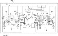
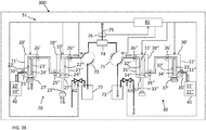
- FIGS. 3A and 3B show schematically a liquid chromatographic (LC) system 300 and a method of exchanging liquid 10', 10" with another liquid 11', 11", respectively, in the liquid chromatographic system 300 according to a second embodiment of the present disclosure.
- LC liquid chromatographic
- the LC system 300 comprises a binary liquid chromatography pump 51 comprising a first pump head 20 comprising a first primary pump head 20' and first secondary pump head 20" and a second pump head 30 comprising a second primary pump head 30' and second secondary pump head 30", respectively, each comprising a syringe-like cylinder body 21', 21", 31', 31", respectively, having an inner wall surface 22', 22", 32', 32" and a plunger 23', 23", 33', 33” translatable through the cylinder body 21', 21", 31', 31" leaving an interspace 24', 24", 34', 34" between the inner wall surface 22', 22", 32', 32" and the plunger 23', 23", 33', 33" when the plunger 23', 23", 33', 33" is translated through the cylinder body 21', 21", 31', 31" through a liquid-tight seal 27', 27", 37', 37
- each of the primary pump heads 20', 30' and of the secondary pump heads 20", 30" comprises a one-way upstream inlet valve 25', 35', 25", 35" for letting liquids 10', 10", 11', 11" into the respective cylinder bodies 21', 21", 31', 31" and preventing liquids 10', 10", 11', 11” from getting out through the same valves 25', 35', 25", 35", and a one-way downstream outlet valve 26', 36', 26", 36" for letting liquids 10', 10", 11', 11” out of the respective cylinder bodies 21', 21", 31', 31” and preventing liquids 10', 10", 11', 11” to get into the cylinder bodies 21', 21", 31', 31" through the same valves 26', 36', 26", 36", respectively.
- the downstream outlet valves 26', 36' of the primary pump heads 20', 30' are connected to the upstream inlet valves 25", 35" of the secondary pump heads 20", 30", respectively, whereas the upstream inlet valves 25', 35' of the primary pump heads 20', 30' are connected to respective liquid sources 40, 41.
- liquids 10', 10", 11', 11" can flow from the liquid sources 40, 41 into the primary pump heads 20', 30' through the upstream inlet valves 25', 35' of the primary pump heads 20', 30' and out of the primary pump heads 20', 30' into the secondary pump heads 20", 30" through the downstream outlet valves 26', 36' of the primary pump heads 20', 30' and the upstream inlet valves 25", 35" of the secondary pump heads 20", 30" and out of the secondary pump heads 20", 30" through the downstream outlet valves 26", 36" of the secondary pump heads 20", 30".
- the downstream outlet valve 26" of the first secondary pump head 20" and the downstream outlet valve 36" of the second secondary pump head 30" are connected to a first purge switch valve 70 and to a second purge switch valve 71, respectively, and the first and second purge switch valves 70, 71 are individually connected to a waste 72, 73 and also to each other via a junction 74 and to an analytical input 75 via the junction 74.
- the LC system 300 comprises a first liquid-exchange pump 62 connected to the downstream outlet valve 26" of the first secondary pump head 20" via the first purge switch valve 70 and a second liquid-exchange pump 63 connected to the downstream outlet valve 36" of the second secondary pump head 30" via the second purge switch valve 71, respectively.
- first liquid-exchange pump 62 and the second liquid-exchange pump 63 are negative-pressure liquid exchange pumps configured to generate a negative-pressure (via a vacuum source) and to draw liquids 10", 11" from the respective liquid sources 40, 41 connected to the respective upstream inlet valves 25', 35' of the first primary pump head 20' and second primary pump head 30', respectively, all the way through the first and second pump heads 20, 30, respectively, thereby exchanging the liquids 10', 11' present therein.
- the wastes 72, 73 are placed between the purge switch valves 70, 71 and the negative-pressure liquid-exchange pumps 62, 63, respectively, in order to trap liquids into the respective wastes 72, 73.
- the LC system 300 comprises a software-driven controller 81 cooperating with a pressure sensor 76 for alternating liquid exchange between the first pump head 20 and the second pump head 30 while maintaining the pressure at the analytical input 75 constant or within a predetermined range.
- the controller 81 is further programmed to control operation of the first and second pump heads 20, 30 and of the liquid exchange pumps 62, 63, e.g., by sending and/or managing on/off signals and/or operational parameters like pressure, speed, time to/for each of them at specific times according to scheduled workflow steps or plan.
- the controller 81 is further programmed to alternately switch the first purge switch valve 70 and the second purge switch valve 71 in order to divert liquid from the pump head where liquid is being exchanged to waste while liquid from the other pump head continues to flow to the analytical input 75.
- the controller 81 is further programmed to alternately switch the first purge switch valve 70 and the second purge switch valve 71 in order to divert liquid from the pump head where liquid is being exchanged to waste while liquid from the other pump head continues to flow to the analytical input 75.
- the controller 81 switches the second purge switch valve 71 and operates the second negative-pressure liquid exchange pump 63 in order to divert liquid 11', 11" from the pump head 30 where liquid 11' is being exchanged with liquid 11" to waste 73 whereas liquid 10' from the other pump head 20 is sent to the analytical input 75 by reciprocating action of the plungers 23', 23" of the first pump head 20.
- the controller 81 may further regulate the liquid pressure by the first pump head 20 in order to maintain the liquid pressure at the analytical input 75 constant or within a predetermined range while liquid 11', 11" from the second pump head 30 is diverted to waste 73. It is easy to imagine how the controller 81 alternates switching, based on FIG. 3B .
- FIG. 4A and 4B show schematically a liquid chromatographic (LC) system 400 and a method of exchanging liquid 10', 10" with another liquid 11', 11", respectively, in the liquid chromatographic system 400 according to a third embodiment of the present disclosure.
- LC liquid chromatographic
- the LC system 400 comprises a binary liquid chromatography pump 52 comprising a first pump head 20 comprising a first primary pump head 20' and first secondary pump head 20" and a second pump head 30 comprising a second primary pump head 30' and second secondary pump head 30", respectively, each comprising a syringe-like cylinder body 21', 21", 31', 31", respectively, having an inner wall surface 22', 22", 32', 32" and a plunger 23', 23", 33', 33” translatable through the cylinder body 21', 21", 31', 31" leaving an interspace 24', 24", 34', 34" between the inner wall surface 22', 22", 32', 32" and the plunger 23', 23", 33', 33" when the plunger 23', 23", 33', 33" is translated through the cylinder body 21', 21", 31', 31"
- each of the primary pump heads 20', 30' and of the secondary pump heads 20", 30" comprises a one-way upstream inlet valve 25', 35', 25", 35" for letting liquids 10', 10", 11', 11" into the respective cylinder bodies 21', 21", 31', 31" and preventing liquids 10', 10", 11', 11” from getting out through the same valves 25', 35', 25", 35", and a one-way downstream outlet valve 26', 36', 26", 36" for letting liquids 10', 10", 11', 11” out of the respective cylinder bodies 21', 21", 31', 31” and preventing liquids 10', 10", 11', 11” to get into the cylinder bodies 21', 21", 31', 31" through the same valves 26', 36', 26", 36", respectively.
- the downstream outlet valves 26', 36' of the primary pump heads 20', 30' are connected to the upstream inlet valves 25", 35" of the secondary pump heads 20", 30", respectively, whereas the upstream inlet valves 25', 35' of the primary pump heads 20', 30' are connected to respective liquid sources 40, 41.
- liquids 10', 10", 11', 11" can flow from the liquid sources 40, 41 into the primary pump heads 20', 30' through the upstream inlet valves 25', 35' of the primary pump heads 20', 30' and out of the primary pump heads 20', 30' into the secondary pump heads 20", 30" through the downstream outlet valves 26', 36' of the primary pump heads 20', 30' and the upstream inlet valves 25", 35" of the secondary pump heads 20", 30" and out of the secondary pump heads 20", 30" through the downstream outlet valves 26", 36" of the secondary pump heads 20", 30".
- the downstream outlet valve 26" of the first secondary pump head 20" and the downstream outlet valve 36" of the second secondary pump head 20" are connected via a junction 77 to a common purge switch valve 78, the common purge switch valve 78 comprising a junction inlet port 78a connected to the junction 77, two bypass ports 78b, 78c interconnected by a bypass fluidic path 79, and two liquid-exchange pump ports 78d, 78e interconnected by a common liquid exchange pump 64 and an output port 78f.
- the output port 78f is connected to a flow splitter 90 for diverting part of liquid to waste 91 and part of the liquid to the analytical input 75.
- the common liquid-exchange pump 64 is a negative-pressure liquid exchange pump configured to generate a negative-pressure and to draw liquids 10", 11" from the respective liquid sources 40, 41 connected to the respective upstream inlet valves 25', 35' of the first primary pump head 20' and second primary pump head 30', respectively, all the way through the first and second pump heads 20, 30, respectively, thereby exchanging the liquids 10', 11' present therein.
- the LC system 400 comprises a software-driven controller 82 cooperating with a pressure sensor 76 and programmed to regulate the flow splitter 90 for enabling simultaneous liquid exchange at both the first pump head 20 and the second pump head 30 while maintaining the pressure at the analytical input 75 constant or within a predetermined range.
- the controller 82 is further programmed to switch the common purge switch valve 78 in order to alternately connect the junction inlet port 78a and the output port 78f via the bypass ports 78b, 78c ( FIG. 4A ) and via the liquid-exchange pump ports 78d, 78e ( FIG. 4B ), respectively, and, at the same time, based on pressure feedback from the pressure sensor 76 can vary the relative flow rate between the analytical input 75 and the waste 91 in order to maintain the liquid pressure at the analytical input 75 constant or within a predetermined range.
Landscapes
- Engineering & Computer Science (AREA)
- General Health & Medical Sciences (AREA)
- Immunology (AREA)
- Chemical & Material Sciences (AREA)
- Analytical Chemistry (AREA)
- Biochemistry (AREA)
- Physics & Mathematics (AREA)
- General Physics & Mathematics (AREA)
- Life Sciences & Earth Sciences (AREA)
- Pathology (AREA)
- Health & Medical Sciences (AREA)
- Mechanical Engineering (AREA)
- General Engineering & Computer Science (AREA)
- Computer Hardware Design (AREA)
- Treatment Of Liquids With Adsorbents In General (AREA)
Abstract
Description
- The present disclosure is related to a system and to a method for liquid exchange in liquid chromatography.
- There is growing interest for the implementation of mass spectrometry and more specifically of liquid chromatography coupled to mass spectrometry in the clinical laboratory. However, the lack of standardized and automated procedures and the complexity of the analytical setup limit its implementation. In particular, sample preparation is typically a manual and tedious procedure. Protein precipitation with subsequent centrifugation is the most popular method to remove unwanted and potentially disturbing sample matrix. The use of kits may in part facilitate sample preparation that can be at least in part automated. Kits are however available only for a limited number of analytes of interest and the entire process from sample preparation, to separation and detection remains complex, requiring the attendance of highly trained laboratory personnel to run highly sophisticated instruments.
- Also, typically, a batch approach is followed, where a batch of samples prepared in advance under the same preparation conditions undergo consecutive chromatographic separation runs under the same separation conditions. This approach however does not enable high throughput and is not flexible, e.g., does not allow processing samples in random order and does not allow re-scheduling (changing a pre-defined processing sequence) in view for example of incoming emergency samples that have higher priority and have to be processed first.
-
U.S. Patent Application Pub. No. 2018/0292368 A1 describes a system and a method enabling automated random-access sample preparation and LC separation, thereby making use of LC coupled to mass spectrometry suitable for clinical diagnostics. - For high-throughput applications requiring many consecutive sample injection cycles, and especially for random-access analysis of different samples possibly requiring different injection conditions and different LC separation conditions, even more flexibility and speed in quickly changing and adapting the conditions for each sample in a scheduled sequence, is important.
- In particular, it may be required to frequently exchange solvent/eluent used for the LC separations. Typically, solvent/eluent exchange in liquid chromatography is done by repeated filling of pump cylinders and subsequent expelling of the liquid. Due to the nature of pump action and to internal dead volumes, liquid exchange is a process of repeated dilution of the previously used liquid by the newly used liquid. This process is time consuming, requiring up to several minutes, and therefore represents a bottleneck if the goal is to achieve high-throughput random-access sample processing.
- Moreover, liquid exchange is typically associated with a temporary loss of liquid pressure, which may reduce LC column lifetime and chromatographic performance.
- It is against the above background that the embodiments of the present disclosure provide certain unobvious advantages and advancements over the prior art. In particular, the inventors have recognized a need for improvements in quick liquid exchange in liquid chromatography.
- Although the embodiments of the present disclosure are not limited to specific advantages or functionality, it is noted that the present disclosure allows for a liquid chromatographic (LC) system and a method of exchanging a liquid in a liquid chromatographic system which enable quicker liquid exchange in liquid chromatography and therefore enable high-throughput random-access liquid chromatography, eventually coupled to mass spectrometry. Another advantage of the system and method herein disclosed is that a loss of liquid pressure during liquid exchange can be prevented, thereby extending LC column lifetime and improving chromatographic performance.
- In particular, the liquid chromatographic system of the present disclosure comprises a liquid chromatography pump comprising at least one pump head comprising a primary pump head and a secondary pump head, each comprising a syringe-like cylinder body having an inner wall surface and a plunger translatable through the cylinder body leaving an interspace between the inner wall surface and the plunger when the plunger is translated through the cylinder body, an upstream inlet valve configured to allow liquid into the cylinder body and a downstream outlet valve configured to allow liquid out of the cylinder body, the downstream outlet valve of the primary pump head being connected to the upstream inlet valve of the secondary pump head. The liquid chromatographic system further comprises at least one liquid-exchange pump connected either to the upstream inlet valve of the primary pump head or to the downstream outlet valve of the secondary pump head, the liquid exchange pump configured for exchanging a liquid present in the cylinder bodies of the primary and secondary pump heads with another liquid by purging through the interspaces left between the inner wall surfaces of the cylinder bodies and the plungers, respectively.
- "Liquid chromatography or LC" is an analytical process that subjects samples injected by a sample injector to chromatographic separation through a LC column in order for example to separate analytes of interest from matrix components, e.g., remaining matrix components after sample preparation that may still interfere with a subsequent detection, e.g., a mass spectrometry detection, and/or in order to separate analytes of interest from each other in order to enable their individual detection. "High-performance liquid chromatography" or HPLC, "ultra-high-performance liquid chromatography" or UHPLC, "micro liquid chromatography" or µLC and "small-bore liquid chromatography" or small-bore LC are forms of liquid chromatography performed under pressure.
- A "liquid chromatographic system or LC system" is an analytical apparatus or module or a unit in an analytical apparatus for carrying out liquid chromatography. The LC system may be embodied as a single channel or as a multi-channel system that may comprise one or a plurality of LC columns arranged in parallel and/or in series. The LC system may also comprise elements such as a sample injector, valves, liquid sources, fluidic connections and parts, e.g., for mixing liquids, degassing liquids, tempering liquids, and the like, one or more sensors, such as pressure sensors, temperature sensors and the like, and especially at least one LC pump. The list is not exhaustive. According to an embodiment, the LC system is an analytical module designed to prepare a sample for mass spectrometry and/or to transfer a prepared sample to a mass spectrometer, in particular for separating analytes of interest before detection by a mass spectrometer. In particular, typically, during an LC run, the mass spectrometer may be set to scan a specific mass range. LC/MS data can be represented by adding up the ion current in the individual mass scans and plotting that "totaled" ion current as an intensity point against time. The resulting plot looks like an HPLC UV trace with analyte peaks. The LC system may otherwise comprise a detector of its own such as a UV detector.
- An "LC channel" is a fluidic line comprising at least one capillary tubing and/or LC column comprising a stationary phase selected according to the type of sample(s) and analytes and through which a mobile phase is pumped in order to trap and/or separate and elute and/or transfer analytes of interest under selected conditions, e.g., according to their polarity or log P value, size or affinity, as generally known. The at least one LC column in the at least one LC channel may be exchangeable. In particular, the LC system may comprise more LC columns than LC channels, where a plurality of LC columns may be interchangeably coupled to the same LC channel. Capillary tubing may be also used to bypass LC columns.
- An "LC column" may refer to any of a column, a cartridge, a capillary and the like for performing separations of a chromatographic nature. Columns are typically packed or loaded with a stationary phase, through which a mobile phase is pumped in order to trap and/or separate and elute and/or transfer analytes of interest under selected conditions, e.g., according to their polarity or log P value, size or affinity, as generally known. This stationary phase can be particulate or beadlike or a porous monolith. However, the term "column" may also refer to capillaries which are not packed or loaded with a stationary phase but rely on the surface area of the inner capillary wall to effect separations. The LC column may be exchangeable and/or operate in parallel or in sequence to one or more other LC columns. An LC column may be for example a rapid trap and elute online LC column, a high-performance LC (HPLC) column or an ultra-high-performance LC (UHPLC) column, and may be of any size, including micro-LC columns and small-bore LC columns with an inner diameter of less than 1 mm.
- A "liquid chromatography pump or LC pump" is a high-pressure pump that may vary in pressure capacity but that can yield a consistent and reproducible volumetric flow rate though an LC channel. Pressure in HPLC may typically reach as high as 60 MPa or about 600 atmospheres, whereas UHPLC and µ-LC systems have been developed to work at even higher pressures, e.g. up to 140 MPa or about 1400 atmospheres, and therefore are able to use much smaller particle sizes in the LC columns (<2 µm). LC pumps may be configured as binary pumps, e.g. in case of conditions requiring the use of elution gradients.
- According to one embodiment, the LC pump can yield a pressure of 60 MPa to 140 MPa, e.g. 75 MPa to 100 MPa, e.g. 80 MPa.
- According to one embodiment, the LC pump can be configured to operate with a flow rate between 1 µl/min and 500 µl/min or more, and typically operate at flow rates between 100 µl/min to 300 µl/min and an accuracy of e.g. about ± 5% or less.
- The LC pump may comprise more than one pump head. For example, binary pumps comprise two pump heads and each pump head typically comprises a primary pump head and a secondary pump head cooperating with each other for pumping liquid while maintaining the liquid pressure inside the pump head about constant. In particular, each of the primary pump head and of the secondary pump head is typically a syringe-like pump comprising a syringe-like cylinder body having an inner wall surface and a plunger translatable through the cylinder body leaving an interspace between the inner wall surface and the plunger when the plunger is translated through the cylinder body. Also, each of the primary pump head and of the secondary pump head comprises a one-way upstream inlet valve for letting liquid into the cylinder body and preventing liquid from getting out through the same valve and a one-way downstream outlet valve for letting liquid out of the cylinder body and preventing liquid to get into the cylinder body through the same valve. The downstream outlet valve of the primary pump head is connected to the upstream inlet valve of the secondary pump head, whereas the upstream inlet valve of the primary pump head is connected to a liquid source. In this way, liquid can flow from the liquid source into the primary pump head through the upstream inlet valve of the primary pump head and out of the primary pump head into the secondary pump head through the downstream outlet valve of the primary pump head and the upstream inlet valve of the secondary pump head and out of the secondary pump head through the downstream outlet valve of the secondary pump head, by reciprocating action and translation of the plungers of the primary pump head and of the secondary pump head, respectively, through liquid-tight seals.
- A "liquid-exchange pump" is an auxiliary pump distinguished at least in function from the LC pump, the main or sole function being that to facilitate and to speed up liquid exchange within the pump head(s) of the LC pump. In general, the liquid-exchange pump is a lower-pressure and higher-volume (higher-flow-rate) pump compared to the LC pump and is fluidically connected either to the upstream inlet valve of the primary pump head or to the downstream outlet valve of the secondary pump head, for exchanging a liquid present in the cylinder bodies of the primary and secondary pump heads with another liquid by purging through the interspaces left between the inner wall surfaces of the cylinder bodies and the plungers, respectively. Typically, the liquid-exchange pump according to the present disclosure is also a lower-precision pump and hence also simpler and cheaper in construction compared to an LC pump.
- The term "liquid" refers to liquids commonly used in liquid chromatography, e.g., as solvents or mixtures of solvents used, e.g., as mobile phases or eluents and as known in the art.
- According to an embodiment, the LC pump is a binary pump comprising a first pump head comprising a first primary pump head and first secondary pump head, and a second pump head comprising a second primary pump head and second secondary pump head, respectively. The downstream outlet valve of the first secondary pump head and the downstream outlet valve of the second secondary pump head are connected to a first purge switch valve and to a second purge switch valve, respectively, and the first and second purge switch valves are individually connected to a waste and also to each other via a junction and to an analytical input via the junction.
- According to an embodiment, the LC system comprises a first positive-pressure liquid-exchange pump connected to the upstream inlet valve of the first primary pump head and a second positive-pressure liquid-exchange pump connected to the upstream inlet valve of the second primary pump head, respectively. Any liquid-exchange pumps suitable to generate a positive-pressure in order to actively pump liquid from respective liquid sources into the respective first and second pump heads via the respective upstream inlet valves of the first primary pump head and second primary pump head, respectively, may be used, like for example membrane/diaphragm pumps, single-plunger high-speed pumps, syringe-piston pumps, gear pumps and the like. According to an embodiment, positive pressure and active pumping may be achieved by applying pneumatic pressure, e.g., by pressurized gas, e.g., by a nitrogen supply, into a sealed liquid container connected to the upstream inlet valve.
- According to an embodiment, the LC system comprises a first negative-pressure liquid-exchange pump connected to the downstream outlet valve of the first secondary pump head via the first purge switch valve and a second negative-pressure liquid-exchange pump connected to the downstream outlet valve of the second secondary pump head via the second purge switch valve, respectively. Any liquid-exchange pumps suitable to generate a negative-pressure (vacuum source) in order to aspirate liquids from respective liquid sources connected to the respective upstream inlet valves of the first primary pump head and second primary pump head, respectively, may be used, analogously to the positive-pressure liquid-exchange pumps. Advantageously, a waste may be placed between the first purge switch valve and the first positive-pressure liquid-exchange pump and between the second purge switch valve and the second positive-pressure liquid-exchange pump, respectively, in order to trap liquids being replaced into the respective waste.
- According to an embodiment, the LC system comprises a software-driven controller and a pressure sensor cooperating with each other for alternating liquid exchange between the first pump head and the second pump head while maintaining the pressure at the analytical input constant or within a predetermined range.
- According to an embodiment, the controller is programmed to switch the first purge switch valve and the second purge switch valve in order to divert liquid from the pump head where liquid is being exchanged to waste and liquid from the other pump head to the analytical input.
- According to an embodiment, the LC pump is a binary pump comprising a first pump head comprising a first primary pump head and first secondary pump head and a second pump head comprising a second primary pump head and second secondary pump head, respectively. However, the downstream outlet valve of the first secondary pump head and the downstream outlet valve of the second secondary pump head are connected via a junction to a common purge switch valve, the common purge switch valve comprising a junction inlet port connected to the junction, two bypass ports interconnected by a bypass fluidic path, two liquid-exchange pump ports interconnected by a common liquid exchange pump and an output port.
- According to an embodiment, the output port is connected to a flow splitter for diverting part of liquid to waste and part of the liquid to an analytical input.
- According to an embodiment, the LC system comprises a software-driven controller cooperating with a pressure sensor and programmed to regulate the flow splitter for enabling simultaneous liquid exchange at both the first pump head and the second pump head while maintaining the pressure at the analytical input constant or within a predetermined range.
- According to an embodiment, the controller is further programmed to switch the common purge switch valve in order to alternately connect the junction inlet port and the output port via the bypass ports and via the liquid-exchange pump ports, respectively.
- The term "valve" refers to a flow-regulating device to control, redirect, restrict or stop flow. For example, the upstream inlet valve(s) and the downstream outlet valve(s) as already mentioned are one-way valves for letting liquid into and out of the cylinder bodies of the pump head in only one direction, i.e., from upstream to downstream, and preventing liquid from flowing in the opposite direction.
- A "purge switch valve" is an LC switching valve, that is a multi-port valve that controls flow between elements connected to the ports. This is typically achieved by moving one or more valve conduits to switch communication between different elements. Elements may be fluidically connected to the ports via further conduits, like pipes, tubes, capillaries, microfluidic channels and the like and by fittings like screws/nuts and ferrules, or alternative liquid-tight seals, e.g., maintained in place by a clamp mechanism. An LC switching valve is normally capable of allowing liquid pressures in the order of magnitude used for HPLC or higher. In particular, a purge switch valve comprises a purge port connected to a waste.
- According to an embodiment, the purge switch valve has an inner valve conduit(s) with an inner diameter of less than 0.6 mm, e.g., between about 0.5 mm and 0.2 mm, e.g., about 0.4 mm or about 0.25 mm.
- According to an embodiment, the purge switch valve has a switching time of about 500 ms or less.
- The term "flow splitter" refers to a device that based on pressure feedback from a pressure sensor can vary the relative flow rate between two fluidic lines in order to maintain the liquid pressure within one of the fluidic lines constant or within a predetermined range. Typically, one of the fluidic lines is connected to a waste and the other fluidic line to an analytical input.
- The term "analytical input" refers to fluidic connection to an analytical part of an LC channel, comprising, e.g., a sample injector, comprising, e.g., a sample loop, and/or an LC column.
- The term "software-driven controller" as used herein encompasses any physical or virtual processing device and in particular a programmable logic controller running a computer-readable program provided with instructions to perform operations in accordance with an operation plan and in particular associated with operation of the liquid exchange pumps in order to alternate liquid exchange between the first pump head and the second pump head while maintaining the pressure at the analytical input constant or within a predetermined range, taking eventually into account readouts from one or more pressure sensors, and switching purge switch valves and/or regulating a flow splitter as needed in an automated manner.
- The controller may be a separate logic entity in communication with the LC system. In some embodiments, the controller might be integral with a data management unit, may be comprised by a server computer and/or be part of one clinical diagnostic system or even distributed across a plurality of LC systems.
- The controller may be also configurable to control the LC system in a way that workflow(s) and workflow step(s) are conducted by the LC system.
- In particular, the controller may communicate and/or cooperate with a scheduler and/or data manager in order to take into account incoming analysis orders and/or received analysis orders and a number of scheduled process operations associated with the execution of the analysis orders in order to schedule and execute liquid exchange.
- The present disclosure also refers to a method of exchanging a liquid in an LC system comprising an LC pump comprising at least one pump head comprising a primary pump head and a secondary pump head, each comprising a syringe-like cylinder body having an inner wall surface and a plunger translatable through the cylinder body leaving an interspace between the inner wall surface and the plunger when the plunger is translated through the cylinder body, an upstream inlet valve for letting liquid into the cylinder body and a downstream outlet valve for letting liquid out of the cylinder body, the downstream outlet valve of the primary pump head being connected to the upstream inlet valve of the secondary pump head. The method comprises exchanging the liquid present in the cylinder bodies of the primary and secondary pump heads with another liquid by purging through the interspaces left between the inner wall surfaces of the cylinder bodies and the plungers, respectively, by at least one liquid-exchange pump connected either to the upstream inlet valve of the primary pump head or to the downstream outlet valve of the secondary pump head.
- According to an embodiment, the liquid chromatography pump is a binary pump comprising a first pump head comprising a first primary pump head and first secondary pump head and a second pump head comprising a second primary pump head and second secondary pump head, respectively, and where the downstream outlet valve of the first secondary pump head and the downstream outlet valve of the second secondary pump head are connected to a first purge switch valve and to a second purge switch valve, respectively, and the first and second purge switch valves are individually connected to a waste and also to each other via a junction and to an analytical input via the junction, and the method comprises alternating liquid exchange between the first pump head and the second pump head while maintaining the pressure at the analytical input constant or within a predetermined range by a software-driven controller cooperating with a pressure sensor.
- According to an embodiment, the method comprises switching the first purge switch valve and the second purge switch valve in order to divert liquid from the pump head where liquid is being exchanged to waste and liquid from the other pump head to the analytical input.
- According to an embodiment, the liquid chromatography pump is a binary pump comprising a first pump head comprising a first primary pump head and first secondary pump head and a second pump head comprising a second primary pump head and second secondary pump head, respectively, and where the downstream outlet valve of the first secondary pump head and the downstream outlet valve of the second secondary pump head are connected via a junction to a common purge switch valve, the common purge switch valve comprising a junction inlet port connected to the junction, two bypass ports interconnected by a bypass fluidic path, two liquid-exchange pump ports interconnected by a common liquid exchange pump and an output port connected to a flow splitter for diverting part of liquid to waste and part of the liquid to an analytical input, and the method comprises regulating the flow splitter for enabling simultaneous liquid exchange at both the first pump head and the second pump head while maintaining the pressure at the analytical input constant or within a predetermined range by a software-driven controller cooperating with a pressure sensor.
- According to an embodiment, the method comprises switching the common purge switch valve in order to alternately connect the junction inlet port and the output port via the bypass ports and via the liquid-exchange pump ports, respectively.
- Other and further objects, features and advantages will appear from the following description of exemplary embodiments in combination with the drawings and the accompanying claims. It is noted that the scope of the claims is defined by the recitations therein and not by the specific discussion of features and advantages set forth in the present description.
- The following detailed description of the embodiments of the present disclosure can be best understood when read in conjunction with the following drawings, where like structure is indicated with like reference numerals and in which:
-
FIG. 1 shows schematically a liquid chromatographic system and a method of exchanging liquid in a liquid chromatographic system according to the prior art; -
FIG. 2A shows schematically a liquid chromatographic system and a method of exchanging liquid in the liquid chromatographic system according to a first embodiment of the present disclosure; -
FIG. 2B is a continuation of the first embodiment ofFIG. 2A ; -
FIG. 3A shows schematically a liquid chromatographic system and a method of exchanging liquid in the liquid chromatographic system according to a second embodiment of the present disclosure; -
FIG. 3B is a continuation of the second embodiment ofFIG. 3A ; -
FIG. 4A shows schematically a liquid chromatographic system and a method of exchanging liquid in the liquid chromatographic system according to a third embodiment of the present disclosure; and. -
FIG. 4B is a continuation of the first embodiment ofFIG. 4A . - Skilled artisans appreciate that elements in the figures are illustrated for simplicity and clarity and have not necessarily been drawn to scale. For example, the dimensions of some of the elements in the figures may be exaggerated relative to other elements to help improve understanding of the embodiments of the present disclosure.
-
FIG. 1 shows schematically aliquid chromatographic system 100 and a method of exchangingliquid 10', 10" with another liquid 11', 11", respectively, in theliquid chromatographic system 100 according to the prior art. In particular, thesystem 100 comprises a binaryliquid chromatography pump 15 comprising afirst pump head 20 comprising a first primary pump head 20' and firstsecondary pump head 20" and asecond pump head 30 comprising a second primary pump head 30' and secondsecondary pump head 30", respectively, each comprising a syringe-like cylinder body 21', 21", 31', 31", respectively, having aninner wall surface 22', 22", 32', 32" and aplunger 23', 23", 33', 33" translatable through thecylinder body 21', 21", 31', 31" leaving aninterspace 24', 24", 34', 34" between theinner wall surface 22', 22", 32', 32" and theplunger 23', 23", 33', 33" when theplunger 23', 23", 33', 33" is translated through thecylinder body 21', 21", 31', 31". - Also, each of the primary pump heads 20', 30' and of the secondary pump heads 20", 30" comprises a one-way
upstream inlet valve 25', 35', 25", 35" for lettingliquids 10', 10", 11', 11" into therespective cylinder bodies 21', 21", 31', 31" and preventingliquids 10', 10", 11', 11" from getting out through thesame valves 25', 35', 25", 35" and a one-waydownstream outlet valve 26', 36', 26", 36" for lettingliquids 10', 10", 11', 11" out of therespective cylinder bodies 21', 21", 31', 31" and preventingliquids 10', 10", 11', 11" to get into thecylinder bodies 21', 21", 31', 31" through thesame valves 25', 35', 25", 35", respectively. The downstream outlet valves 26', 36' of the primary pump heads 20', 30' are connected to theupstream inlet valves 25", 35" of the secondary pump heads 20", 30", respectively, whereas the upstream inlet valves 25', 35' of the primary pump head 20', 30' are connected to respectiveliquid sources liquids 10', 10", 11', 11" can flow from theliquid sources upstream inlet valves 25", 35" of the secondary pump heads 20", 30" and out of the secondary pump heads 20", 30" through thedownstream outlet valves 26", 36" of the secondary pump heads 20", 30", by reciprocating action and translation of theplungers 23', 33', 23", 33" of the primary pump heads 20', 30' and of the secondary pump heads 20", 30", respectively, through liquid-tight seals 27', 37', 27", 37". - Liquid exchange occurs by repeated filling of the
pump cylinders 21', 21", 31', 31" and subsequent expelling of the previous liquids 10', 11' while drawing thenew liquids 10", 11". Due to the nature of pump action and to theinterspaces 24', 24", 34', 34", liquid exchange is a process of repeated dilution of the previously used liquids 10', 11' by the newly usedliquids 10", 11". This process is time consuming, requiring up to several minutes, and therefore represents a bottleneck if the goal is to achieve high-throughput random-access sample processing with frequent liquid exchange. -
FIGS. 2A and2B show schematically a liquid chromatographic (LC)system 200 and a method of exchangingliquid 10', 10" with another liquid 11', 11", respectively, in theliquid chromatographic system 200 according to a first embodiment of the present disclosure. In particular, thesystem 200 comprises a binaryliquid chromatography pump 50 comprising afirst pump head 20 comprising a first primary pump head 20' and firstsecondary pump head 20" and asecond pump head 30 comprising a second primary pump head 30' and secondsecondary pump head 30", respectively, each comprising a syringe-like cylinder body 21', 21", 31', 31", respectively, having aninner wall surface 22', 22", 32', 32" and aplunger 23', 23", 33', 33" translatable through thecylinder body 21', 21", 31', 31" leaving aninterspace 24', 24", 34', 34" between theinner wall surface 22', 22", 32', 32" and theplunger 23', 23", 33', 33" when theplunger 23', 23", 33', 33" is translated through thecylinder body 21', 21", 31', 31" through a liquid-tight seal 27', 27", 37', 37", respectively. - Also, each of the primary pump heads 20', 30' and of the secondary pump heads 20", 30" comprises a one-way
upstream inlet valve 25', 35', 25", 35" for lettingliquids 10', 10", 11', 11" into therespective cylinder bodies 21', 21", 31', 31" and preventingliquids 10', 10", 11', 11" from getting out through thesame valves 25', 35', 25", 35", and a one-waydownstream outlet valve 26', 36', 26", 36" for lettingliquids 10', 10", 11', 11" out of therespective cylinder bodies 21', 21", 31', 31" and preventingliquids 10', 10", 11', 11" to get into thecylinder bodies 21', 21", 31', 31" through thesame valves 26', 36', 26", 36", respectively. The downstream outlet valves 26', 36' of the primary pump heads 20', 30' are connected to theupstream inlet valves 25", 35" of the secondary pump heads 20", 30", respectively, whereas the upstream inlet valves 25', 35' of the primary pump heads 20', 30' are connected to respectiveliquid sources liquids 10', 10", 11', 11" can flow from theliquid sources upstream inlet valves 25", 35" of the secondary pump heads 20", 30" and out of the secondary pump heads 20", 30" through thedownstream outlet valves 26", 36" of the secondary pump heads 20", 30". - The
LC system 200 further comprises a first liquid-exchange pump 60 connected to the upstream inlet valve 25' of the primary pump head 20' of thefirst pump head 20 and a second liquid-exchange pump 61 connected to the upstream inlet valve 35' of the primary pump head 30' of thesecond pump head 30, for exchanging the liquids present in the cylinder bodies 10', 11' of the primary and secondary pump heads 20', 20", 30', 30" of the first and second pump heads 20, 30, respectively, withother liquids 10", 11" by purging through theinterspaces 24', 24", 34', 34" left between the inner wall surfaces 22', 22", 32', 32" of thecylinder bodies 21', 21", 31', 31" and theplungers 23', 23", 33', 33", respectively. - Also, the
downstream outlet valve 26" of the firstsecondary pump head 20" and thedownstream outlet valve 36" of the secondsecondary pump head 30" are connected to a firstpurge switch valve 70 and to a secondpurge switch valve 71, respectively, and the first and secondpurge switch valves waste junction 74 and to ananalytical input 75 via thejunction 74. - The first liquid-
exchange pump 60 and the second liquid-exchange pump 61 are positive-pressure liquid exchange pumps configured to drawliquids 10", 11" from theliquid sources way valves 28, 38 and actively pump theliquids 10", 11" through the first and second pump heads 20, 30, respectively, in order to exchange the liquids 10', 11' present therein. - The
LC system 200 further comprises a software-drivencontroller 80 cooperating with apressure sensor 76 for alternating liquid exchange between thefirst pump head 20 and thesecond pump head 30 while maintaining the pressure at theanalytical input 75 constant or within a predetermined range. Thecontroller 80 is further programmed to control operation of the first and second pump heads 20, 30 and of the liquid-exchange pumps 60, 61, e.g., by sending and/or managing on/off signals and/or operational parameters like pressure, speed, time to/for each of them at specific times according to scheduled workflow steps or plan. - In particular, as it can be seen in
FIG. 2B , which is a continuation of the first embodiment ofFIG. 2A , thecontroller 80 is further programmed to alternately switch the firstpurge switch valve 70 and the secondpurge switch valve 71 in order to divert liquid from the pump head where liquid is being exchanged to waste while liquid from the other pump head continues to flow to theanalytical input 75. InFIG. 2B , it is shown as an example when thecontroller 80 switches the secondpurge switch valve 71 and operates the second positive-pressureliquid exchange pump 61 in order to divert liquid 11', 11" from thepump head 30 where liquid 11' is being exchanged withliquid 11" to waste 73, whereas liquid 10' from theother pump head 20 is sent to theanalytical input 75 by reciprocating action of theplungers 23', 23" of thefirst pump head 20. In particular, thecontroller 80 may further regulate the liquid pressure by thefirst pump head 20 in order to maintain the liquid pressure at theanalytical input 75 constant or within a predetermined range while liquid 11', 11" from thesecond pump head 30 is diverted to waste 73. It is easy to imagine how thecontroller 80 alternates switching, based onFIG. 2B . -
FIGS. 3A and3B show schematically a liquid chromatographic (LC)system 300 and a method of exchangingliquid 10', 10" with another liquid 11', 11", respectively, in theliquid chromatographic system 300 according to a second embodiment of the present disclosure. - In particular, analogously to the
LC system 200 ofFIGS. 2A ,2B , theLC system 300 comprises a binaryliquid chromatography pump 51 comprising afirst pump head 20 comprising a first primary pump head 20' and firstsecondary pump head 20" and asecond pump head 30 comprising a second primary pump head 30' and secondsecondary pump head 30", respectively, each comprising a syringe-like cylinder body 21', 21", 31', 31", respectively, having aninner wall surface 22', 22", 32', 32" and aplunger 23', 23", 33', 33" translatable through thecylinder body 21', 21", 31', 31" leaving aninterspace 24', 24", 34', 34" between theinner wall surface 22', 22", 32', 32" and theplunger 23', 23", 33', 33" when theplunger 23', 23", 33', 33" is translated through thecylinder body 21', 21", 31', 31" through a liquid-tight seal 27', 27", 37', 37", respectively. - Also, each of the primary pump heads 20', 30' and of the secondary pump heads 20", 30" comprises a one-way
upstream inlet valve 25', 35', 25", 35" for lettingliquids 10', 10", 11', 11" into therespective cylinder bodies 21', 21", 31', 31" and preventingliquids 10', 10", 11', 11" from getting out through thesame valves 25', 35', 25", 35", and a one-waydownstream outlet valve 26', 36', 26", 36" for lettingliquids 10', 10", 11', 11" out of therespective cylinder bodies 21', 21", 31', 31" and preventingliquids 10', 10", 11', 11" to get into thecylinder bodies 21', 21", 31', 31" through thesame valves 26', 36', 26", 36", respectively. The downstream outlet valves 26', 36' of the primary pump heads 20', 30' are connected to theupstream inlet valves 25", 35" of the secondary pump heads 20", 30", respectively, whereas the upstream inlet valves 25', 35' of the primary pump heads 20', 30' are connected to respectiveliquid sources liquids 10', 10", 11', 11" can flow from theliquid sources upstream inlet valves 25", 35" of the secondary pump heads 20", 30" and out of the secondary pump heads 20", 30" through thedownstream outlet valves 26", 36" of the secondary pump heads 20", 30". - Just like for the
LC system 200 of the previous example, thedownstream outlet valve 26" of the firstsecondary pump head 20" and thedownstream outlet valve 36" of the secondsecondary pump head 30" are connected to a firstpurge switch valve 70 and to a secondpurge switch valve 71, respectively, and the first and secondpurge switch valves waste junction 74 and to ananalytical input 75 via thejunction 74. - The difference with respect to the
LC system 200 ofFIGS. 2A ,2B is that theLC system 300 comprises a first liquid-exchange pump 62 connected to thedownstream outlet valve 26" of the firstsecondary pump head 20" via the firstpurge switch valve 70 and a second liquid-exchange pump 63 connected to thedownstream outlet valve 36" of the secondsecondary pump head 30" via the secondpurge switch valve 71, respectively. - In particular, the first liquid-
exchange pump 62 and the second liquid-exchange pump 63 are negative-pressure liquid exchange pumps configured to generate a negative-pressure (via a vacuum source) and to drawliquids 10", 11" from the respectiveliquid sources - Advantageously, the
wastes purge switch valves respective wastes - Also the
LC system 300 comprises a software-drivencontroller 81 cooperating with apressure sensor 76 for alternating liquid exchange between thefirst pump head 20 and thesecond pump head 30 while maintaining the pressure at theanalytical input 75 constant or within a predetermined range. Thecontroller 81 is further programmed to control operation of the first and second pump heads 20, 30 and of the liquid exchange pumps 62, 63, e.g., by sending and/or managing on/off signals and/or operational parameters like pressure, speed, time to/for each of them at specific times according to scheduled workflow steps or plan. - In particular, as it can be seen in
FIG. 3B , which is a continuation of the second embodiment ofFIG. 3A , thecontroller 81 is further programmed to alternately switch the firstpurge switch valve 70 and the secondpurge switch valve 71 in order to divert liquid from the pump head where liquid is being exchanged to waste while liquid from the other pump head continues to flow to theanalytical input 75. InFIG. 2B , it is shown as example when thecontroller 81 switches the secondpurge switch valve 71 and operates the second negative-pressureliquid exchange pump 63 in order to divert liquid 11', 11" from thepump head 30 where liquid 11' is being exchanged withliquid 11" to waste 73 whereas liquid 10' from theother pump head 20 is sent to theanalytical input 75 by reciprocating action of theplungers 23', 23" of thefirst pump head 20. In particular, thecontroller 81 may further regulate the liquid pressure by thefirst pump head 20 in order to maintain the liquid pressure at theanalytical input 75 constant or within a predetermined range while liquid 11', 11" from thesecond pump head 30 is diverted to waste 73. It is easy to imagine how thecontroller 81 alternates switching, based onFIG. 3B . -
FIG. 4A and4B show schematically a liquid chromatographic (LC)system 400 and a method of exchangingliquid 10', 10" with another liquid 11', 11", respectively, in theliquid chromatographic system 400 according to a third embodiment of the present disclosure. - In particular, analogously to the
LC system 200 ofFIGS. 2A ,2B and to theLC system 300 ofFIGS. 3A ,3B , theLC system 400 comprises a binaryliquid chromatography pump 52 comprising afirst pump head 20 comprising a first primary pump head 20' and firstsecondary pump head 20" and asecond pump head 30 comprising a second primary pump head 30' and secondsecondary pump head 30", respectively, each comprising a syringe-like cylinder body 21', 21", 31', 31", respectively, having aninner wall surface 22', 22", 32', 32" and aplunger 23', 23", 33', 33" translatable through thecylinder body 21', 21", 31', 31" leaving aninterspace 24', 24", 34', 34" between theinner wall surface 22', 22", 32', 32" and theplunger 23', 23", 33', 33" when theplunger 23', 23", 33', 33" is translated through thecylinder body 21', 21", 31', 31" through a liquid-tight seal 27', 27", 37', 37", respectively. - Also, each of the primary pump heads 20', 30' and of the secondary pump heads 20", 30" comprises a one-way
upstream inlet valve 25', 35', 25", 35" for lettingliquids 10', 10", 11', 11" into therespective cylinder bodies 21', 21", 31', 31" and preventingliquids 10', 10", 11', 11" from getting out through thesame valves 25', 35', 25", 35", and a one-waydownstream outlet valve 26', 36', 26", 36" for lettingliquids 10', 10", 11', 11" out of therespective cylinder bodies 21', 21", 31', 31" and preventingliquids 10', 10", 11', 11" to get into thecylinder bodies 21', 21", 31', 31" through thesame valves 26', 36', 26", 36", respectively. The downstream outlet valves 26', 36' of the primary pump heads 20', 30' are connected to theupstream inlet valves 25", 35" of the secondary pump heads 20", 30", respectively, whereas the upstream inlet valves 25', 35' of the primary pump heads 20', 30' are connected to respectiveliquid sources liquids 10', 10", 11', 11" can flow from theliquid sources upstream inlet valves 25", 35" of the secondary pump heads 20", 30" and out of the secondary pump heads 20", 30" through thedownstream outlet valves 26", 36" of the secondary pump heads 20", 30". - However, unlike the
LC systems LC system 400 thedownstream outlet valve 26" of the firstsecondary pump head 20" and thedownstream outlet valve 36" of the secondsecondary pump head 20" are connected via ajunction 77 to a commonpurge switch valve 78, the commonpurge switch valve 78 comprising ajunction inlet port 78a connected to thejunction 77, twobypass ports bypass fluidic path 79, and two liquid-exchange pump ports liquid exchange pump 64 and anoutput port 78f. - The
output port 78f is connected to aflow splitter 90 for diverting part of liquid to waste 91 and part of the liquid to theanalytical input 75. - The common liquid-
exchange pump 64 is a negative-pressure liquid exchange pump configured to generate a negative-pressure and to drawliquids 10", 11" from the respectiveliquid sources - Also the
LC system 400 comprises a software-drivencontroller 82 cooperating with apressure sensor 76 and programmed to regulate theflow splitter 90 for enabling simultaneous liquid exchange at both thefirst pump head 20 and thesecond pump head 30 while maintaining the pressure at theanalytical input 75 constant or within a predetermined range. - In particular, as it can be seen in conjunction with
FIG. 4B , which is a continuation of the third embodiment ofFIG. 4A , thecontroller 82 is further programmed to switch the commonpurge switch valve 78 in order to alternately connect thejunction inlet port 78a and theoutput port 78f via thebypass ports FIG. 4A ) and via the liquid-exchange pump ports FIG. 4B ), respectively, and, at the same time, based on pressure feedback from thepressure sensor 76 can vary the relative flow rate between theanalytical input 75 and thewaste 91 in order to maintain the liquid pressure at theanalytical input 75 constant or within a predetermined range. This is achieved by controlling the operation of the first and second pump heads 20, 30, of the commonliquid exchange pump 64, theflow splitter 90 and the commonpurge switch valve 78, e.g., by sending and/or managing on/off signals and/or operational parameters like pressure, speed, time to/for each of them at specific times according to scheduled workflow steps or plan. - In the preceding specification, numerous specific details are set forth in order to provide a thorough understanding of the present disclosure. It will be apparent, however, to one having ordinary skill in the art, that the specific detail need not be employed to practice the present teaching. In other instances, well-known materials or methods have not been described in detail in order to avoid obscuring the present disclosure.
- Particularly, modifications and variations of the disclosed embodiments are certainly possible in light of the above description. It is therefore to be understood, that within the scope of the appended claims, the invention may be practiced otherwise than as specifically devised in the above examples.
- Reference throughout the preceding specification to "one embodiment", "an embodiment", "one example" or "an example", means that a particular feature, structure or characteristic described in connection with the embodiment or example is included in at least one embodiment. Thus, appearances of the phrases "in one embodiment", "in an embodiment", "one example" or "an example", in various places throughout this specification are not necessarily all referring to the same embodiment or example.
- Furthermore, the particular features, structures, or characteristics may be combined in any suitable combinations and / or sub-combinations in one or more embodiments or examples.
Claims (15)
- A liquid chromatographic (LC) system (200, 300, 400) comprising a liquid chromatography pump (50, 51, 52) comprising at least one pump head (20, 30) comprising a primary pump head (20', 30') and a secondary pump head (20", 30"), each comprising a syringe-like cylinder body (21', 21", 31', 31") having an inner wall surface (22', 22", 32', 32") and a plunger (23', 23", 33', 33") translatable through the cylinder body (21', 21", 31', 31") leaving an interspace (24', 24", 34', 34") between the inner wall surface (22', 22", 32', 32") and the plunger (23', 23", 33', 33") when the plunger (23', 23", 33', 33") is translated through the cylinder body (21', 21", 31', 31"), an upstream inlet valve (25', 25", 35', 35") for letting liquid (10', 10", 11', 11") into the cylinder body (21', 21", 31', 31") and a downstream outlet valve (26', 26", 36', 36") for letting liquid (10', 10", 11', 11") out of the cylinder body (21', 21", 31', 31"), the downstream outlet valve (26', 36') of the primary pump head (20', 30') being connected to the upstream inlet valve (25", 35") of the secondary pump head (20", 30"),
characterized in that the LC system (200, 300, 400) further comprises at least one liquid-exchange pump (60, 61, 62, 63, 64) connected either to the upstream inlet valve (25', 35') of the primary pump head (20', 30') or to the downstream outlet valve (26", 36") of the secondary pump head (20", 30"), for exchanging a liquid (10', 11') present in the cylinder bodies (21', 21", 31', 31") of the primary and secondary pump heads (20', 30', 20", 30") with another liquid (10", 11") by purging through the interspaces (24', 24", 34', 34") left between the inner wall surfaces (22', 22", 32', 32") of the cylinder bodies (21', 21", 31', 31") and the plungers (23', 23", 33', 33"), respectively. - The LC system (200, 300) according to claim 1 wherein the liquid chromatography pump (50, 51) is a binary pump comprising a first pump head (20) comprising a first primary pump head (20') and first secondary pump head (20") and a second pump head (30) comprising a second primary pump head (30') and second secondary pump head (30"), respectively, and wherein the downstream outlet valve (26") of the first secondary pump head (20") and the downstream outlet valve (36") of the second secondary pump head (30") are connected to a first purge switch valve (70) and to a second purge switch valve (71), respectively, and the first and second purge switch valves (70, 71) are individually connected to a waste (72, 73) and also to each other via a junction (74) and to an analytical input (75) via the junction (74).
- The LC system (200) according to claim 2 comprising a first positive-pressure liquid-exchange pump (60) connected to the upstream inlet valve (25') of the first primary pump head (20') and a second positive-pressure liquid-exchange pump (61) connected to the upstream inlet valve (35') of the second primary pump head (30'), respectively.
- The LC system (300) according to claim 2 comprising a first negative-pressure liquid-exchange pump (62) connected to the downstream outlet valve (26") of the first secondary pump head (20") via the first purge switch valve (70) and a second negative-pressure liquid-exchange pump (63) connected to the downstream outlet valve (36") of the second secondary pump head (30") via the second purge switch valve (71), respectively.
- The LC system (200, 300) according to any of the claims 2 to 4 comprising a software-driven controller (80, 81) cooperating with a pressure sensor (76) for alternating liquid exchange between the first pump head (20) and the second pump head (30) while maintaining the pressure at the analytical input (75) constant or within a predetermined range.
- The LC system (200, 300) according to claim 5 wherein the controller (80, 81) is programmed to switch the first purge switch valve (70) and the second purge switch valve (71) in order to divert liquid from the pump head (30) where liquid is being exchanged to waste (73) and liquid from the other pump head (20) to the analytical input (75).
- The LC system (400) according to claim 1 wherein the liquid chromatography pump (52) is a binary pump comprising a first pump head (20) comprising a first primary pump head (20') and first secondary pump head (20") and a second pump head (30) comprising a second primary pump head (30') and second secondary pump head (30"), respectively, and wherein the downstream outlet valve (26") of the first secondary pump head (20") and the downstream outlet valve (36") of the second secondary pump head (30") are connected via a junction (77) to a common purge switch valve (78), the common purge switch valve (78) comprising a junction inlet port (78a) connected to the junction (77), two bypass ports (78b, 78c) interconnected by a bypass fluidic path (79), two liquid-exchange pump ports (78d, 78e) interconnected by a common liquid exchange pump (64) and an output port (78f).
- The LC system (400) according to claim 7 wherein the output port (78f) is connected to a flow splitter (90) for diverting part of liquid to waste (91) and part of the liquid to an analytical input (75).
- The LC system (400) according to claim 8 comprising a software-driven controller (82) cooperating with a pressure sensor (76) and programmed to regulate the flow splitter (90) for enabling simultaneous liquid exchange at both the first pump head (20) and the second pump head (30) while maintaining the pressure at the analytical input (75) constant or within a predetermined range.
- The LC system (400) according to claim 9 wherein the controller (82) is further programmed to switch the common purge switch valve (78) in order to alternately connect the junction inlet port (78a) and the output port (78f) via the bypass ports (78b, 78c) and via the liquid-exchange pump ports (78d, 78e), respectively.
- A method of exchanging a liquid in a liquid chromatographic (LC) system (200, 300, 400) comprising a liquid chromatography pump (50, 51, 52) comprising at least one pump head (20, 30) comprising a primary pump head (20', 30') and a secondary pump head (20", 30"), each comprising a syringe-like cylinder body (21', 21", 31', 31") having an inner wall surface (22', 22", 32', 32") and a plunger (23', 23", 33', 33") translatable through the cylinder body (21', 21", 31', 31") leaving an interspace (24', 24", 34', 34") between the inner wall surface (22', 22", 32', 32") and the plunger (23', 23", 33', 33") when the plunger (23', 23", 33', 33") is translated through the cylinder body (21', 21", 31', 31"), an upstream inlet valve (25', 25", 35', 35") for letting liquid (10', 10", 11', 11") into the cylinder body (21', 21", 31', 31") and a downstream outlet valve (26', 26", 36', 36") for letting liquid (10', 10", 11', 11") out of the cylinder body (21', 21", 31', 31"), the downstream outlet valve (26', 36') of the primary pump head (20', 30') being connected to the upstream inlet valve (25", 35") of the secondary pump head (20", 30"),
the method comprising exchanging the liquid (10', 11') present in the cylinder bodies (21', 21", 31', 31") of the primary and secondary pump heads (20', 30', 20", 30") with another liquid (10", 11") by purging through the interspaces (24', 24", 34', 34") left between the inner wall surfaces (22', 22", 32', 32") of the cylinder bodies (21', 21", 31', 31") and the plungers (23', 23", 33', 33"), respectively, by at least one liquid-exchange pump (60, 61, 62, 63, 64) connected either to the upstream inlet valve (25', 35') of the primary pump head) or to the downstream outlet valve (26", 36") of the secondary pump head (20", 30"). - The method according to claim 11 wherein the liquid chromatography pump (50, 51) is a binary pump comprising a first pump head (20) comprising a first primary pump head (20') and first secondary pump head (20") and a second pump head (30) comprising a second primary pump head (30') and second secondary pump head (30"), respectively, and wherein the downstream outlet valve (26") of the first secondary pump head (20") and the downstream outlet valve (36") of the second secondary pump head (30") are connected to a first purge switch valve (70) and to a second purge switch valve (71), respectively, and the first and second purge switch valves (70, 71) are individually connected to a waste (72, 73) and also to each other via a junction (74) and to an analytical input (75) via the junction (74),
the method comprising alternating liquid exchange between the first pump head (20) and the second pump head (30) while maintaining the pressure at the analytical input (75) constant or within a predetermined range by a software-driven controller (80, 81) cooperating with a pressure sensor (76). - The method according to claim 12 comprising switching the first purge switch valve (70) and the second purge switch valve (71) in order to divert liquid from the pump head (30) where liquid is being exchanged to waste (73) and liquid from the other pump head (20) to the analytical input (75).
- The method according to claim 11 wherein the liquid chromatography pump (52) is a binary pump comprising a first pump head (20) comprising a first primary pump head (20') and first secondary pump head (20") and a second pump head (30) comprising a second primary pump head (30') and second secondary pump head (30"), respectively, and wherein the downstream outlet valve (26") of the first secondary pump head (20") and the downstream outlet valve (36") of the second secondary pump head (30") are connected via a junction (77) to a common purge switch valve (78), the common purge switch valve (78) comprising a junction inlet port (78a) connected to the junction (77), two bypass ports (78b, 78c) interconnected by a bypass fluidic path (79), two liquid-exchange pump ports (78d, 78e) interconnected by a common liquid exchange pump (64) and an output port (78f) connected to a flow splitter (90) for diverting part of liquid to waste (91) and part of the liquid to an analytical input (75),
the method comprising regulating the flow splitter (90) for enabling simultaneous liquid exchange at both the first pump head (20) and the second pump head (30) while maintaining the pressure at the analytical input (75) constant or within a predetermined range by a software-driven controller (82) cooperating with a pressure sensor (76). - The method according to claim 14 comprising switching the common purge switch valve (78) in order to alternately connect the junction inlet port (78a) and the output port (78f) via the bypass ports (78b, 78c) and via the liquid-exchange pump ports (78d, 78e), respectively.
Priority Applications (5)
| Application Number | Priority Date | Filing Date | Title |
|---|---|---|---|
| EP19178228.3A EP3748354B1 (en) | 2019-06-04 | 2019-06-04 | Quick liquid exchange in liquid chromatography |
| ES19178228T ES2915839T3 (en) | 2019-06-04 | 2019-06-04 | Rapid Liquid Exchange in Liquid Chromatography |
| US15/931,152 US11454615B2 (en) | 2019-06-04 | 2020-05-13 | Quick liquid exchange in liquid chromatography |
| JP2020095876A JP6955057B2 (en) | 2019-06-04 | 2020-06-02 | Rapid liquid exchange in liquid chromatography |
| CN202010494583.3A CN112034082B (en) | 2019-06-04 | 2020-06-03 | Fast liquid exchange in liquid chromatography |
Applications Claiming Priority (1)
| Application Number | Priority Date | Filing Date | Title |
|---|---|---|---|
| EP19178228.3A EP3748354B1 (en) | 2019-06-04 | 2019-06-04 | Quick liquid exchange in liquid chromatography |
Publications (2)
| Publication Number | Publication Date |
|---|---|
| EP3748354A1 true EP3748354A1 (en) | 2020-12-09 |
| EP3748354B1 EP3748354B1 (en) | 2022-04-06 |
Family
ID=66999548
Family Applications (1)
| Application Number | Title | Priority Date | Filing Date |
|---|---|---|---|
| EP19178228.3A Active EP3748354B1 (en) | 2019-06-04 | 2019-06-04 | Quick liquid exchange in liquid chromatography |
Country Status (5)
| Country | Link |
|---|---|
| US (1) | US11454615B2 (en) |
| EP (1) | EP3748354B1 (en) |
| JP (1) | JP6955057B2 (en) |
| CN (1) | CN112034082B (en) |
| ES (1) | ES2915839T3 (en) |
Cited By (1)
| Publication number | Priority date | Publication date | Assignee | Title |
|---|---|---|---|---|
| US12306147B2 (en) * | 2020-04-15 | 2025-05-20 | Roche Diagnostics Operations, Inc. | Analytical system and method including switching between liquid chromatography fluidic streams |
Families Citing this family (2)
| Publication number | Priority date | Publication date | Assignee | Title |
|---|---|---|---|---|
| JP7186113B2 (en) * | 2019-03-01 | 2022-12-08 | 株式会社日立ハイテク | liquid transfer pump, liquid chromatograph |
| CN115656354B (en) * | 2022-09-16 | 2025-06-06 | 中国烟草总公司郑州烟草研究院 | A two-dimensional liquid chromatography separation system |
Citations (5)
| Publication number | Priority date | Publication date | Assignee | Title |
|---|---|---|---|---|
| GB2338433A (en) * | 1998-06-19 | 1999-12-22 | Shimadzu Corp | Liquid Chromatograph |
| WO2009062538A1 (en) * | 2007-11-12 | 2009-05-22 | Agilent Technologies, Inc. | Hplc-system with variable flow rate |
| US20150345484A1 (en) * | 2012-09-11 | 2015-12-03 | Warner DÖBELIN | Syringe pump system for pulse-free metering and precise mixing in hplc uhplc, micro-hplc and nano-hplc |
| EP3136095A1 (en) * | 2015-08-28 | 2017-03-01 | Dionex Corporation | Systems and apparatus for reducing signal noise due to pump oscillations |
| US20180292368A1 (en) | 2015-12-18 | 2018-10-11 | Roche Diagnostics Operations, Inc. | Automated clinical diagnostic system and method |
Family Cites Families (17)
| Publication number | Priority date | Publication date | Assignee | Title |
|---|---|---|---|---|
| US4681513A (en) | 1985-02-01 | 1987-07-21 | Jeol Ltd. | Two-stage pump assembly |
| JPS61178582A (en) * | 1985-02-01 | 1986-08-11 | Jeol Ltd | Liquid feeding pump apparatus |
| CN1014549B (en) * | 1985-04-01 | 1991-10-30 | 株式会社岛津制作所 | Liquid chromatograph |
| JP3389649B2 (en) * | 1993-09-17 | 2003-03-24 | 株式会社島津製作所 | Liquid sending device |
| EP0655769A1 (en) | 1993-11-17 | 1995-05-31 | Hewlett-Packard Company | Method and apparatus for preparing an electrospray ion source sample |
| JPH10339267A (en) | 1997-06-05 | 1998-12-22 | Dkk Corp | Liquid feeding mechanism, sampling mechanism using the liquid feeding mechanism and column chromatography device |
| JP4228502B2 (en) * | 2000-03-08 | 2009-02-25 | 株式会社島津製作所 | Liquid chromatograph and flow path switching valve |
| JP3839238B2 (en) * | 2000-09-22 | 2006-11-01 | 株式会社日立製作所 | Sample introduction apparatus, liquid chromatograph apparatus using the same, and sample introduction method |
| JP2002168843A (en) | 2000-12-05 | 2002-06-14 | Metocean Environment Inc | Automatic substance purification equipment |
| JP4812524B2 (en) * | 2006-06-07 | 2011-11-09 | ジーエルサイエンス株式会社 | Liquid supply method and apparatus |
| CA2703991A1 (en) * | 2007-11-02 | 2009-05-07 | Biotrove, Inc. | Devices and methods for coupling mass spectrometry devices with chromatography systems |
| WO2018055866A1 (en) | 2016-09-26 | 2018-03-29 | 株式会社島津製作所 | Switching valve, binary pump, and liquid chromatograph provided with binary pump |
| DE102018104842A1 (en) * | 2018-03-02 | 2018-04-19 | Agilent Technologies, Inc. - A Delaware Corporation - | Fluid mixing by means of fluid supply lines with line-specific associated fluid pumps for liquid chromatography |
| US11879877B2 (en) * | 2018-03-16 | 2024-01-23 | Shimadzu Corporation | Binary pump and liquid chromatograph provided with same |
| US11808252B2 (en) * | 2018-05-16 | 2023-11-07 | Shimadzu Corporation | Liquid delivery device and liquid chromatograph |
| EP3617701B1 (en) * | 2018-08-27 | 2024-10-23 | F. Hoffmann-La Roche AG | Sample injector with sample loop and buffer loop |
| EP3896443B1 (en) * | 2020-04-15 | 2024-05-01 | F. Hoffmann-La Roche AG | Analytical system and method including switching between liquid chromatography fluidic streams |
-
2019
- 2019-06-04 EP EP19178228.3A patent/EP3748354B1/en active Active
- 2019-06-04 ES ES19178228T patent/ES2915839T3/en active Active
-
2020
- 2020-05-13 US US15/931,152 patent/US11454615B2/en active Active
- 2020-06-02 JP JP2020095876A patent/JP6955057B2/en active Active
- 2020-06-03 CN CN202010494583.3A patent/CN112034082B/en active Active
Patent Citations (5)
| Publication number | Priority date | Publication date | Assignee | Title |
|---|---|---|---|---|
| GB2338433A (en) * | 1998-06-19 | 1999-12-22 | Shimadzu Corp | Liquid Chromatograph |
| WO2009062538A1 (en) * | 2007-11-12 | 2009-05-22 | Agilent Technologies, Inc. | Hplc-system with variable flow rate |
| US20150345484A1 (en) * | 2012-09-11 | 2015-12-03 | Warner DÖBELIN | Syringe pump system for pulse-free metering and precise mixing in hplc uhplc, micro-hplc and nano-hplc |
| EP3136095A1 (en) * | 2015-08-28 | 2017-03-01 | Dionex Corporation | Systems and apparatus for reducing signal noise due to pump oscillations |
| US20180292368A1 (en) | 2015-12-18 | 2018-10-11 | Roche Diagnostics Operations, Inc. | Automated clinical diagnostic system and method |
Cited By (1)
| Publication number | Priority date | Publication date | Assignee | Title |
|---|---|---|---|---|
| US12306147B2 (en) * | 2020-04-15 | 2025-05-20 | Roche Diagnostics Operations, Inc. | Analytical system and method including switching between liquid chromatography fluidic streams |
Also Published As
| Publication number | Publication date |
|---|---|
| CN112034082A (en) | 2020-12-04 |
| ES2915839T3 (en) | 2022-06-27 |
| JP2020197532A (en) | 2020-12-10 |
| US20200386721A1 (en) | 2020-12-10 |
| US11454615B2 (en) | 2022-09-27 |
| JP6955057B2 (en) | 2021-10-27 |
| CN112034082B (en) | 2023-07-25 |
| EP3748354B1 (en) | 2022-04-06 |
Similar Documents
| Publication | Publication Date | Title |
|---|---|---|
| US11454615B2 (en) | Quick liquid exchange in liquid chromatography | |
| US9032819B2 (en) | Liquid sampling valve | |
| US9833754B2 (en) | Sample dilution to specifiable dilution ratio | |
| US11300548B2 (en) | Liquid chromatography systems | |
| EP3617701B1 (en) | Sample injector with sample loop and buffer loop | |
| EP3896443B1 (en) | Analytical system and method including switching between liquid chromatography fluidic streams | |
| US20150204828A1 (en) | Fluidic valve with selectivly switchable storage paths | |
| CN104285145A (en) | Two-dimensional fluid separation with controlled pressure | |
| US10677766B2 (en) | Volumetric flow regulation in multi-dimensional liquid analysis systems | |
| US12055526B2 (en) | Sample handling and dispatching individual sample packages for fluid processing | |
| WO2012175111A1 (en) | Two-dimensional fluid separation with first separation unit feeding to high-pressure end of second separation unit | |
| EP2788639B1 (en) | Select valve for liquid chromatography systems | |
| GB2588635A (en) | Sample injector with fluidic sample mixing | |
| US20160054273A1 (en) | Two-dimensional liquid chromatography system for heart-cut method | |
| US12123856B2 (en) | LC system and method with column backflushing | |
| US11898997B2 (en) | Sample injector | |
| CN121114255A (en) | Liquid chromatography analysis system | |
| GB2597469A (en) | Pressurizing fluid by expanding membrane |
Legal Events
| Date | Code | Title | Description |
|---|---|---|---|
| PUAI | Public reference made under article 153(3) epc to a published international application that has entered the european phase |
Free format text: ORIGINAL CODE: 0009012 |
|
| STAA | Information on the status of an ep patent application or granted ep patent |
Free format text: STATUS: THE APPLICATION HAS BEEN PUBLISHED |
|
| AK | Designated contracting states |
Kind code of ref document: A1 Designated state(s): AL AT BE BG CH CY CZ DE DK EE ES FI FR GB GR HR HU IE IS IT LI LT LU LV MC MK MT NL NO PL PT RO RS SE SI SK SM TR |
|
| AX | Request for extension of the european patent |
Extension state: BA ME |
|
| STAA | Information on the status of an ep patent application or granted ep patent |
Free format text: STATUS: REQUEST FOR EXAMINATION WAS MADE |
|
| 17P | Request for examination filed |
Effective date: 20210609 |
|
| RBV | Designated contracting states (corrected) |
Designated state(s): AL AT BE BG CH CY CZ DE DK EE ES FI FR GB GR HR HU IE IS IT LI LT LU LV MC MK MT NL NO PL PT RO RS SE SI SK SM TR |
|
| GRAP | Despatch of communication of intention to grant a patent |
Free format text: ORIGINAL CODE: EPIDOSNIGR1 |
|
| STAA | Information on the status of an ep patent application or granted ep patent |
Free format text: STATUS: GRANT OF PATENT IS INTENDED |
|
| INTG | Intention to grant announced |
Effective date: 20211108 |
|
| GRAS | Grant fee paid |
Free format text: ORIGINAL CODE: EPIDOSNIGR3 |
|
| GRAA | (expected) grant |
Free format text: ORIGINAL CODE: 0009210 |
|
| STAA | Information on the status of an ep patent application or granted ep patent |
Free format text: STATUS: THE PATENT HAS BEEN GRANTED |
|
| AK | Designated contracting states |
Kind code of ref document: B1 Designated state(s): AL AT BE BG CH CY CZ DE DK EE ES FI FR GB GR HR HU IE IS IT LI LT LU LV MC MK MT NL NO PL PT RO RS SE SI SK SM TR |
|
| REG | Reference to a national code |
Ref country code: GB Ref legal event code: FG4D |
|
| REG | Reference to a national code |
Ref country code: CH Ref legal event code: EP |
|
| REG | Reference to a national code |
Ref country code: AT Ref legal event code: REF Ref document number: 1481800 Country of ref document: AT Kind code of ref document: T Effective date: 20220415 |
|
| REG | Reference to a national code |
Ref country code: IE Ref legal event code: FG4D |
|
| REG | Reference to a national code |
Ref country code: DE Ref legal event code: R096 Ref document number: 602019013279 Country of ref document: DE |
|
| REG | Reference to a national code |
Ref country code: ES Ref legal event code: FG2A Ref document number: 2915839 Country of ref document: ES Kind code of ref document: T3 Effective date: 20220627 |
|
| REG | Reference to a national code |
Ref country code: LT Ref legal event code: MG9D |
|
| REG | Reference to a national code |
Ref country code: NL Ref legal event code: MP Effective date: 20220406 |
|
| REG | Reference to a national code |
Ref country code: AT Ref legal event code: MK05 Ref document number: 1481800 Country of ref document: AT Kind code of ref document: T Effective date: 20220406 |
|
| PG25 | Lapsed in a contracting state [announced via postgrant information from national office to epo] |
Ref country code: NL Free format text: LAPSE BECAUSE OF FAILURE TO SUBMIT A TRANSLATION OF THE DESCRIPTION OR TO PAY THE FEE WITHIN THE PRESCRIBED TIME-LIMIT Effective date: 20220406 |
|
| PG25 | Lapsed in a contracting state [announced via postgrant information from national office to epo] |
Ref country code: SE Free format text: LAPSE BECAUSE OF FAILURE TO SUBMIT A TRANSLATION OF THE DESCRIPTION OR TO PAY THE FEE WITHIN THE PRESCRIBED TIME-LIMIT Effective date: 20220406 Ref country code: PT Free format text: LAPSE BECAUSE OF FAILURE TO SUBMIT A TRANSLATION OF THE DESCRIPTION OR TO PAY THE FEE WITHIN THE PRESCRIBED TIME-LIMIT Effective date: 20220808 Ref country code: NO Free format text: LAPSE BECAUSE OF FAILURE TO SUBMIT A TRANSLATION OF THE DESCRIPTION OR TO PAY THE FEE WITHIN THE PRESCRIBED TIME-LIMIT Effective date: 20220706 Ref country code: LT Free format text: LAPSE BECAUSE OF FAILURE TO SUBMIT A TRANSLATION OF THE DESCRIPTION OR TO PAY THE FEE WITHIN THE PRESCRIBED TIME-LIMIT Effective date: 20220406 Ref country code: HR Free format text: LAPSE BECAUSE OF FAILURE TO SUBMIT A TRANSLATION OF THE DESCRIPTION OR TO PAY THE FEE WITHIN THE PRESCRIBED TIME-LIMIT Effective date: 20220406 Ref country code: GR Free format text: LAPSE BECAUSE OF FAILURE TO SUBMIT A TRANSLATION OF THE DESCRIPTION OR TO PAY THE FEE WITHIN THE PRESCRIBED TIME-LIMIT Effective date: 20220707 Ref country code: FI Free format text: LAPSE BECAUSE OF FAILURE TO SUBMIT A TRANSLATION OF THE DESCRIPTION OR TO PAY THE FEE WITHIN THE PRESCRIBED TIME-LIMIT Effective date: 20220406 Ref country code: BG Free format text: LAPSE BECAUSE OF FAILURE TO SUBMIT A TRANSLATION OF THE DESCRIPTION OR TO PAY THE FEE WITHIN THE PRESCRIBED TIME-LIMIT Effective date: 20220706 Ref country code: AT Free format text: LAPSE BECAUSE OF FAILURE TO SUBMIT A TRANSLATION OF THE DESCRIPTION OR TO PAY THE FEE WITHIN THE PRESCRIBED TIME-LIMIT Effective date: 20220406 |
|
| PG25 | Lapsed in a contracting state [announced via postgrant information from national office to epo] |
Ref country code: RS Free format text: LAPSE BECAUSE OF FAILURE TO SUBMIT A TRANSLATION OF THE DESCRIPTION OR TO PAY THE FEE WITHIN THE PRESCRIBED TIME-LIMIT Effective date: 20220406 Ref country code: PL Free format text: LAPSE BECAUSE OF FAILURE TO SUBMIT A TRANSLATION OF THE DESCRIPTION OR TO PAY THE FEE WITHIN THE PRESCRIBED TIME-LIMIT Effective date: 20220406 Ref country code: LV Free format text: LAPSE BECAUSE OF FAILURE TO SUBMIT A TRANSLATION OF THE DESCRIPTION OR TO PAY THE FEE WITHIN THE PRESCRIBED TIME-LIMIT Effective date: 20220406 Ref country code: IS Free format text: LAPSE BECAUSE OF FAILURE TO SUBMIT A TRANSLATION OF THE DESCRIPTION OR TO PAY THE FEE WITHIN THE PRESCRIBED TIME-LIMIT Effective date: 20220806 |
|
| REG | Reference to a national code |
Ref country code: DE Ref legal event code: R097 Ref document number: 602019013279 Country of ref document: DE |
|
| PG25 | Lapsed in a contracting state [announced via postgrant information from national office to epo] |
Ref country code: SM Free format text: LAPSE BECAUSE OF FAILURE TO SUBMIT A TRANSLATION OF THE DESCRIPTION OR TO PAY THE FEE WITHIN THE PRESCRIBED TIME-LIMIT Effective date: 20220406 Ref country code: SK Free format text: LAPSE BECAUSE OF FAILURE TO SUBMIT A TRANSLATION OF THE DESCRIPTION OR TO PAY THE FEE WITHIN THE PRESCRIBED TIME-LIMIT Effective date: 20220406 Ref country code: RO Free format text: LAPSE BECAUSE OF FAILURE TO SUBMIT A TRANSLATION OF THE DESCRIPTION OR TO PAY THE FEE WITHIN THE PRESCRIBED TIME-LIMIT Effective date: 20220406 Ref country code: MC Free format text: LAPSE BECAUSE OF FAILURE TO SUBMIT A TRANSLATION OF THE DESCRIPTION OR TO PAY THE FEE WITHIN THE PRESCRIBED TIME-LIMIT Effective date: 20220406 Ref country code: EE Free format text: LAPSE BECAUSE OF FAILURE TO SUBMIT A TRANSLATION OF THE DESCRIPTION OR TO PAY THE FEE WITHIN THE PRESCRIBED TIME-LIMIT Effective date: 20220406 Ref country code: DK Free format text: LAPSE BECAUSE OF FAILURE TO SUBMIT A TRANSLATION OF THE DESCRIPTION OR TO PAY THE FEE WITHIN THE PRESCRIBED TIME-LIMIT Effective date: 20220406 Ref country code: CZ Free format text: LAPSE BECAUSE OF FAILURE TO SUBMIT A TRANSLATION OF THE DESCRIPTION OR TO PAY THE FEE WITHIN THE PRESCRIBED TIME-LIMIT Effective date: 20220406 |
|
| PLBE | No opposition filed within time limit |
Free format text: ORIGINAL CODE: 0009261 |
|
| STAA | Information on the status of an ep patent application or granted ep patent |
Free format text: STATUS: NO OPPOSITION FILED WITHIN TIME LIMIT |
|
| REG | Reference to a national code |
Ref country code: BE Ref legal event code: MM Effective date: 20220630 |
|
| 26N | No opposition filed |
Effective date: 20230110 |
|
| PG25 | Lapsed in a contracting state [announced via postgrant information from national office to epo] |
Ref country code: AL Free format text: LAPSE BECAUSE OF FAILURE TO SUBMIT A TRANSLATION OF THE DESCRIPTION OR TO PAY THE FEE WITHIN THE PRESCRIBED TIME-LIMIT Effective date: 20220406 |
|
| PG25 | Lapsed in a contracting state [announced via postgrant information from national office to epo] |
Ref country code: LU Free format text: LAPSE BECAUSE OF NON-PAYMENT OF DUE FEES Effective date: 20220604 Ref country code: IE Free format text: LAPSE BECAUSE OF NON-PAYMENT OF DUE FEES Effective date: 20220604 |
|
| PG25 | Lapsed in a contracting state [announced via postgrant information from national office to epo] |
Ref country code: SI Free format text: LAPSE BECAUSE OF FAILURE TO SUBMIT A TRANSLATION OF THE DESCRIPTION OR TO PAY THE FEE WITHIN THE PRESCRIBED TIME-LIMIT Effective date: 20220406 Ref country code: BE Free format text: LAPSE BECAUSE OF NON-PAYMENT OF DUE FEES Effective date: 20220630 |
|
| PG25 | Lapsed in a contracting state [announced via postgrant information from national office to epo] |
Ref country code: MK Free format text: LAPSE BECAUSE OF FAILURE TO SUBMIT A TRANSLATION OF THE DESCRIPTION OR TO PAY THE FEE WITHIN THE PRESCRIBED TIME-LIMIT Effective date: 20220406 Ref country code: CY Free format text: LAPSE BECAUSE OF FAILURE TO SUBMIT A TRANSLATION OF THE DESCRIPTION OR TO PAY THE FEE WITHIN THE PRESCRIBED TIME-LIMIT Effective date: 20220406 |
|
| PG25 | Lapsed in a contracting state [announced via postgrant information from national office to epo] |
Ref country code: HU Free format text: LAPSE BECAUSE OF FAILURE TO SUBMIT A TRANSLATION OF THE DESCRIPTION OR TO PAY THE FEE WITHIN THE PRESCRIBED TIME-LIMIT; INVALID AB INITIO Effective date: 20190604 |
|
| PG25 | Lapsed in a contracting state [announced via postgrant information from national office to epo] |
Ref country code: MT Free format text: LAPSE BECAUSE OF FAILURE TO SUBMIT A TRANSLATION OF THE DESCRIPTION OR TO PAY THE FEE WITHIN THE PRESCRIBED TIME-LIMIT Effective date: 20220406 |
|
| PG25 | Lapsed in a contracting state [announced via postgrant information from national office to epo] |
Ref country code: BG Free format text: LAPSE BECAUSE OF FAILURE TO SUBMIT A TRANSLATION OF THE DESCRIPTION OR TO PAY THE FEE WITHIN THE PRESCRIBED TIME-LIMIT Effective date: 20220406 |
|
| PG25 | Lapsed in a contracting state [announced via postgrant information from national office to epo] |
Ref country code: BG Free format text: LAPSE BECAUSE OF FAILURE TO SUBMIT A TRANSLATION OF THE DESCRIPTION OR TO PAY THE FEE WITHIN THE PRESCRIBED TIME-LIMIT Effective date: 20220406 |
|
| PGFP | Annual fee paid to national office [announced via postgrant information from national office to epo] |
Ref country code: DE Payment date: 20250520 Year of fee payment: 7 |
|
| PGFP | Annual fee paid to national office [announced via postgrant information from national office to epo] |
Ref country code: GB Payment date: 20250520 Year of fee payment: 7 |
|
| PGFP | Annual fee paid to national office [announced via postgrant information from national office to epo] |
Ref country code: IT Payment date: 20250520 Year of fee payment: 7 |
|
| PGFP | Annual fee paid to national office [announced via postgrant information from national office to epo] |
Ref country code: FR Payment date: 20250520 Year of fee payment: 7 |
|
| PGFP | Annual fee paid to national office [announced via postgrant information from national office to epo] |
Ref country code: ES Payment date: 20250701 Year of fee payment: 7 |
|
| PGFP | Annual fee paid to national office [announced via postgrant information from national office to epo] |
Ref country code: CH Payment date: 20250701 Year of fee payment: 7 |
|
| PG25 | Lapsed in a contracting state [announced via postgrant information from national office to epo] |
Ref country code: TR Free format text: LAPSE BECAUSE OF FAILURE TO SUBMIT A TRANSLATION OF THE DESCRIPTION OR TO PAY THE FEE WITHIN THE PRESCRIBED TIME-LIMIT Effective date: 20220406 |