EP3896443B1 - Analytical system and method including switching between liquid chromatography fluidic streams - Google Patents
Analytical system and method including switching between liquid chromatography fluidic streams Download PDFInfo
- Publication number
- EP3896443B1 EP3896443B1 EP20169521.0A EP20169521A EP3896443B1 EP 3896443 B1 EP3896443 B1 EP 3896443B1 EP 20169521 A EP20169521 A EP 20169521A EP 3896443 B1 EP3896443 B1 EP 3896443B1
- Authority
- EP
- European Patent Office
- Prior art keywords
- fluidic
- stream
- wash
- valve
- detector
- Prior art date
- Legal status (The legal status is an assumption and is not a legal conclusion. Google has not performed a legal analysis and makes no representation as to the accuracy of the status listed.)
- Active
Links
- 238000000034 method Methods 0.000 title claims description 48
- 238000004811 liquid chromatography Methods 0.000 title description 67
- 239000007788 liquid Substances 0.000 claims description 78
- 238000005406 washing Methods 0.000 claims description 12
- 238000004458 analytical method Methods 0.000 claims description 10
- 238000005086 pumping Methods 0.000 claims description 7
- 238000005070 sampling Methods 0.000 claims description 5
- 239000006199 nebulizer Substances 0.000 claims description 3
- 239000000523 sample Substances 0.000 description 18
- 239000002699 waste material Substances 0.000 description 15
- WEVYAHXRMPXWCK-UHFFFAOYSA-N Acetonitrile Chemical compound CC#N WEVYAHXRMPXWCK-UHFFFAOYSA-N 0.000 description 12
- 239000007789 gas Substances 0.000 description 10
- 238000000926 separation method Methods 0.000 description 10
- 239000002904 solvent Substances 0.000 description 10
- OKKJLVBELUTLKV-UHFFFAOYSA-N Methanol Chemical compound OC OKKJLVBELUTLKV-UHFFFAOYSA-N 0.000 description 9
- 230000000694 effects Effects 0.000 description 8
- 230000008901 benefit Effects 0.000 description 7
- 238000000132 electrospray ionisation Methods 0.000 description 7
- 238000004128 high performance liquid chromatography Methods 0.000 description 7
- 150000002500 ions Chemical class 0.000 description 7
- 239000012071 phase Substances 0.000 description 7
- 230000005526 G1 to G0 transition Effects 0.000 description 6
- 238000004949 mass spectrometry Methods 0.000 description 6
- 238000012545 processing Methods 0.000 description 6
- 239000012491 analyte Substances 0.000 description 5
- 238000001514 detection method Methods 0.000 description 5
- 230000008569 process Effects 0.000 description 5
- 238000001195 ultra high performance liquid chromatography Methods 0.000 description 5
- XLYOFNOQVPJJNP-UHFFFAOYSA-N water Substances O XLYOFNOQVPJJNP-UHFFFAOYSA-N 0.000 description 5
- WYURNTSHIVDZCO-UHFFFAOYSA-N Tetrahydrofuran Chemical compound C1CCOC1 WYURNTSHIVDZCO-UHFFFAOYSA-N 0.000 description 4
- 238000002347 injection Methods 0.000 description 4
- 239000007924 injection Substances 0.000 description 4
- XEKOWRVHYACXOJ-UHFFFAOYSA-N Ethyl acetate Chemical compound CCOC(C)=O XEKOWRVHYACXOJ-UHFFFAOYSA-N 0.000 description 3
- KFZMGEQAYNKOFK-UHFFFAOYSA-N Isopropanol Chemical compound CC(C)O KFZMGEQAYNKOFK-UHFFFAOYSA-N 0.000 description 3
- 230000009471 action Effects 0.000 description 3
- 239000000654 additive Substances 0.000 description 3
- 238000000065 atmospheric pressure chemical ionisation Methods 0.000 description 3
- 238000013375 chromatographic separation Methods 0.000 description 3
- 238000004587 chromatography analysis Methods 0.000 description 3
- 238000004891 communication Methods 0.000 description 3
- 239000012156 elution solvent Substances 0.000 description 3
- 238000004895 liquid chromatography mass spectrometry Methods 0.000 description 3
- 239000011159 matrix material Substances 0.000 description 3
- VLKZOEOYAKHREP-UHFFFAOYSA-N n-Hexane Chemical compound CCCCCC VLKZOEOYAKHREP-UHFFFAOYSA-N 0.000 description 3
- 238000002360 preparation method Methods 0.000 description 3
- 150000003839 salts Chemical class 0.000 description 3
- 230000006641 stabilisation Effects 0.000 description 3
- 238000011105 stabilization Methods 0.000 description 3
- 238000012360 testing method Methods 0.000 description 3
- 238000012546 transfer Methods 0.000 description 3
- IJGRMHOSHXDMSA-UHFFFAOYSA-N Atomic nitrogen Chemical compound N#N IJGRMHOSHXDMSA-UHFFFAOYSA-N 0.000 description 2
- HEDRZPFGACZZDS-UHFFFAOYSA-N Chloroform Chemical compound ClC(Cl)Cl HEDRZPFGACZZDS-UHFFFAOYSA-N 0.000 description 2
- LFQSCWFLJHTTHZ-UHFFFAOYSA-N Ethanol Chemical compound CCO LFQSCWFLJHTTHZ-UHFFFAOYSA-N 0.000 description 2
- IMNFDUFMRHMDMM-UHFFFAOYSA-N N-Heptane Chemical compound CCCCCCC IMNFDUFMRHMDMM-UHFFFAOYSA-N 0.000 description 2
- MUMGGOZAMZWBJJ-DYKIIFRCSA-N Testostosterone Chemical compound O=C1CC[C@]2(C)[C@H]3CC[C@](C)([C@H](CC4)O)[C@@H]4[C@@H]3CCC2=C1 MUMGGOZAMZWBJJ-DYKIIFRCSA-N 0.000 description 2
- 238000013459 approach Methods 0.000 description 2
- 230000009286 beneficial effect Effects 0.000 description 2
- 239000000872 buffer Substances 0.000 description 2
- 150000001793 charged compounds Chemical class 0.000 description 2
- 230000008878 coupling Effects 0.000 description 2
- 238000010168 coupling process Methods 0.000 description 2
- 238000005859 coupling reaction Methods 0.000 description 2
- 239000003480 eluent Substances 0.000 description 2
- 238000010828 elution Methods 0.000 description 2
- 238000001704 evaporation Methods 0.000 description 2
- 230000008020 evaporation Effects 0.000 description 2
- 239000012634 fragment Substances 0.000 description 2
- 239000007792 gaseous phase Substances 0.000 description 2
- 238000012423 maintenance Methods 0.000 description 2
- BDAGIHXWWSANSR-UHFFFAOYSA-N methanoic acid Natural products OC=O BDAGIHXWWSANSR-UHFFFAOYSA-N 0.000 description 2
- 239000000203 mixture Substances 0.000 description 2
- 238000002552 multiple reaction monitoring Methods 0.000 description 2
- 239000000243 solution Substances 0.000 description 2
- YLQBMQCUIZJEEH-UHFFFAOYSA-N tetrahydrofuran Natural products C=1C=COC=1 YLQBMQCUIZJEEH-UHFFFAOYSA-N 0.000 description 2
- OSWFIVFLDKOXQC-UHFFFAOYSA-N 4-(3-methoxyphenyl)aniline Chemical compound COC1=CC=CC(C=2C=CC(N)=CC=2)=C1 OSWFIVFLDKOXQC-UHFFFAOYSA-N 0.000 description 1
- USFZMSVCRYTOJT-UHFFFAOYSA-N Ammonium acetate Chemical compound N.CC(O)=O USFZMSVCRYTOJT-UHFFFAOYSA-N 0.000 description 1
- 239000005695 Ammonium acetate Substances 0.000 description 1
- XUIMIQQOPSSXEZ-UHFFFAOYSA-N Silicon Chemical compound [Si] XUIMIQQOPSSXEZ-UHFFFAOYSA-N 0.000 description 1
- 230000002378 acidificating effect Effects 0.000 description 1
- 230000006978 adaptation Effects 0.000 description 1
- 230000000996 additive effect Effects 0.000 description 1
- 235000019257 ammonium acetate Nutrition 0.000 description 1
- 229940043376 ammonium acetate Drugs 0.000 description 1
- VZTDIZULWFCMLS-UHFFFAOYSA-N ammonium formate Chemical compound [NH4+].[O-]C=O VZTDIZULWFCMLS-UHFFFAOYSA-N 0.000 description 1
- 239000012490 blank solution Substances 0.000 description 1
- 230000001413 cellular effect Effects 0.000 description 1
- 238000004140 cleaning Methods 0.000 description 1
- 238000010276 construction Methods 0.000 description 1
- 238000011109 contamination Methods 0.000 description 1
- 238000002425 crystallisation Methods 0.000 description 1
- 230000008025 crystallization Effects 0.000 description 1
- 238000013523 data management Methods 0.000 description 1
- 238000007872 degassing Methods 0.000 description 1
- 230000003111 delayed effect Effects 0.000 description 1
- 230000008021 deposition Effects 0.000 description 1
- 239000003599 detergent Substances 0.000 description 1
- 238000010790 dilution Methods 0.000 description 1
- 239000012895 dilution Substances 0.000 description 1
- 239000006185 dispersion Substances 0.000 description 1
- 238000001035 drying Methods 0.000 description 1
- 238000011067 equilibration Methods 0.000 description 1
- 238000005530 etching Methods 0.000 description 1
- 235000019253 formic acid Nutrition 0.000 description 1
- 238000013467 fragmentation Methods 0.000 description 1
- 238000006062 fragmentation reaction Methods 0.000 description 1
- 230000036541 health Effects 0.000 description 1
- 238000001802 infusion Methods 0.000 description 1
- 238000005040 ion trap Methods 0.000 description 1
- 239000000463 material Substances 0.000 description 1
- 230000007246 mechanism Effects 0.000 description 1
- 239000012528 membrane Substances 0.000 description 1
- 238000002156 mixing Methods 0.000 description 1
- 229910052757 nitrogen Inorganic materials 0.000 description 1
- 230000003287 optical effect Effects 0.000 description 1
- 239000003960 organic solvent Substances 0.000 description 1
- 239000002245 particle Substances 0.000 description 1
- 239000003495 polar organic solvent Substances 0.000 description 1
- 238000011112 process operation Methods 0.000 description 1
- 230000002035 prolonged effect Effects 0.000 description 1
- 239000012088 reference solution Substances 0.000 description 1
- 238000004366 reverse phase liquid chromatography Methods 0.000 description 1
- 230000035945 sensitivity Effects 0.000 description 1
- 229910052710 silicon Inorganic materials 0.000 description 1
- 239000010703 silicon Substances 0.000 description 1
- 239000007787 solid Substances 0.000 description 1
- 238000001179 sorption measurement Methods 0.000 description 1
- 238000001228 spectrum Methods 0.000 description 1
- 239000007921 spray Substances 0.000 description 1
- 238000005496 tempering Methods 0.000 description 1
- 229960003604 testosterone Drugs 0.000 description 1
- 238000011144 upstream manufacturing Methods 0.000 description 1
Images


Classifications
-
- G—PHYSICS
- G01—MEASURING; TESTING
- G01N—INVESTIGATING OR ANALYSING MATERIALS BY DETERMINING THEIR CHEMICAL OR PHYSICAL PROPERTIES
- G01N30/00—Investigating or analysing materials by separation into components using adsorption, absorption or similar phenomena or using ion-exchange, e.g. chromatography or field flow fractionation
- G01N30/02—Column chromatography
- G01N30/26—Conditioning of the fluid carrier; Flow patterns
- G01N30/38—Flow patterns
- G01N30/46—Flow patterns using more than one column
- G01N30/468—Flow patterns using more than one column involving switching between different column configurations
-
- G—PHYSICS
- G01—MEASURING; TESTING
- G01N—INVESTIGATING OR ANALYSING MATERIALS BY DETERMINING THEIR CHEMICAL OR PHYSICAL PROPERTIES
- G01N30/00—Investigating or analysing materials by separation into components using adsorption, absorption or similar phenomena or using ion-exchange, e.g. chromatography or field flow fractionation
- G01N30/02—Column chromatography
- G01N30/26—Conditioning of the fluid carrier; Flow patterns
- G01N30/38—Flow patterns
- G01N30/46—Flow patterns using more than one column
- G01N30/466—Flow patterns using more than one column with separation columns in parallel
-
- G—PHYSICS
- G01—MEASURING; TESTING
- G01N—INVESTIGATING OR ANALYSING MATERIALS BY DETERMINING THEIR CHEMICAL OR PHYSICAL PROPERTIES
- G01N30/00—Investigating or analysing materials by separation into components using adsorption, absorption or similar phenomena or using ion-exchange, e.g. chromatography or field flow fractionation
- G01N30/02—Column chromatography
- G01N30/62—Detectors specially adapted therefor
- G01N30/72—Mass spectrometers
- G01N30/7233—Mass spectrometers interfaced to liquid or supercritical fluid chromatograph
- G01N30/724—Nebulising, aerosol formation or ionisation
-
- G—PHYSICS
- G01—MEASURING; TESTING
- G01N—INVESTIGATING OR ANALYSING MATERIALS BY DETERMINING THEIR CHEMICAL OR PHYSICAL PROPERTIES
- G01N30/00—Investigating or analysing materials by separation into components using adsorption, absorption or similar phenomena or using ion-exchange, e.g. chromatography or field flow fractionation
- G01N30/02—Column chromatography
- G01N30/62—Detectors specially adapted therefor
- G01N2030/628—Multiplexing, i.e. several columns sharing a single detector
Definitions
- the present disclosure is related to an analytical system comprising a plurality of fluidic streams alternately connectable to a common detector and to an analytical method comprising switching between fluidic streams.
- U.S. Patent Application Pub. No. 2018/0292368 A1 describes a system comprising a plurality of LC fluidic streams arranged in parallel and alternately connectable to a mass spectrometer, and a method enabling automated random-access sample preparation and LC separation, thereby making use of LC coupled to mass spectrometry suitable for clinical diagnostics.
- WO-A1-00/45929 describes a liquid chromatographic system comprising a plurality of fluidic streams alternately connectable to a common detector via a stream-selection valve and a wash pump fluidically connected to the stream-selection valve and configured to connect to the valve-to-detector conduit between two consecutive fluidic streams.
- liquid exchange is a process of repeated dilution of the previously used liquid by the newly used liquid, possibly resulting in long equilibration and signal stabilization times. This process therefore may present a bottleneck if the goal is to achieve high-throughput random-access sample processing, in particular if the goal is to maintain a regular pace of sample injection and analysis regardless of the sample sequence and separation/analysis conditions.
- the embodiments of the present disclosure are not limited to specific advantages or functionality, it is noted that the present disclosure provides an analytical system and method, which enable faster and more efficient exchange of the liquid from a previous LC fluidic stream with the liquid of a subsequent LC fluidic stream in the fluidic conduit leading from a stream-selection valve to a detector, thereby resulting in a shorter clearance (signal stabilization) time and hence increased throughput in random-access sample analysis.
- Another advantage of the system and method herein disclosed is minimization of carryover, thus reducing baseline shifts and increasing sensitivity.
- Another advantage of the system and method herein disclosed is that a condition of no flow can be prevented in case of system standby or interrupted liquid chromatography, thereby minimizing surface adsorption effects and contributing to maintain the valve-to-detector conduit cleaner, thus also minimizing maintenance costs and system downtimes.
- Another advantage of the system and method herein disclosed is the enablement of automatic cleaning procedures at convenient times and independently of the liquid chromatography system, hence extending also the lifetime of some system components.
- Another advantage of the system and method herein disclosed may be a standardization of the initial conditions at each fluidic stream switch by, e.g., introducing always the same liquid in between.
- the analytical system in accordance with one embodiment of the present disclosure comprises a liquid chromatographic system comprising a plurality of fluidic streams alternately connectable to a common detector via a stream-selection valve connected to the detector via a valve-to-detector conduit.
- the analytical system further comprises a wash pump fluidically connected to the stream-selection valve and configured to connect to the valve-to-detector conduit between two consecutive fluidic streams in order to wash liquid from a previous fluidic stream out of the valve-to-detector conduit before liquid from a subsequent fluidic stream enters the valve-to-detector conduit.
- Liquid chromatography or LC is an analytical process that subjects samples injected by a sample injector to chromatographic separation through an LC column in order for example to separate analytes of interest from matrix components, e.g., remaining matrix components after sample preparation that may still interfere with a subsequent detection, e.g., a mass spectrometry detection, and/or in order to separate analytes of interest from each other in order to enable their individual detection.
- a subsequent detection e.g., a mass spectrometry detection
- a "liquid chromatographic system or LC system” is an analytical apparatus or module or a unit in an analytical apparatus for carrying out liquid chromatography.
- the LC system may be embodied as a single channel or as a multi-channel system that may comprise one or a plurality of LC columns arranged in parallel and/or in series.
- the LC system may also comprise elements such as a sample injector, valves, liquid sources, fluidic connections and parts, e.g., for mixing liquids, degassing liquids, tempering liquids, and the like, one or more sensors, such as pressure sensors, temperature sensors and the like, and especially at least one LC pump.
- the list is not exhaustive.
- the detector is a mass spectrometer connected to the valve-to-detector conduit via an ionization source.
- the detector may however be something other than a mass spectrometer, such as, i.e., an optical detector, e.g., a UV or fluorescence detector, an impedance detector, a conductivity detector and the like.
- the LC system is configured as an analytical module designed to prepare a sample for mass spectrometry and/or to transfer a prepared sample to a mass spectrometer, in particular for separating analytes of interest before detection by a mass spectrometer.
- the mass spectrometer may be set to scan a specific mass range.
- LC/MS data can be represented by adding up the ion current in the individual mass scans and plotting that "totaled" ion current as an intensity point against time. The resulting plot looks like an HPLC UV trace with analyte peaks.
- a "fluidic stream” is a fluidic path through which liquids can flow and in particular through which a sample from a sample injection point can be transferred to a detector, e.g., to a mass spectrometer or other detector, and through which the sample may undergo a chromatographic process.
- the fluidic connection through different parts of the fluidic stream may be discontinuous. This is because the fluidic stream may comprise elements such as switching valves that may establish alternative connections and regulate fluidic flow between different parts of the fluidic stream at different times.
- the fluidic stream may comprise at least one capillary tubing and/or LC column comprising a stationary phase selected according to the type of sample(s) and analytes of interest, and through which a mobile phase is pumped in order to trap and/or separate and elute and/or transfer analytes of interest under selected conditions, e.g., according to their polarity or log P value, size or affinity, as generally known.
- the at least one LC column may be exchangeable.
- the LC system may comprise more LC columns than fluidic streams, where a plurality of LC columns may be selectable, e.g., interchangeably coupled to the same fluidic stream.
- Capillary tubing may be also used to bypass LC columns.
- a fluidic stream may comprise a plurality of substreams.
- the LC system in accordance with one or more embodiments of the disclosure comprises a plurality of fluidic streams connected to a stream-selection valve for directing flow from one fluidic stream at a time to a detector.
- LC column may refer to any of a column, a cartridge, a capillary and the like for performing separations of a chromatographic nature. Columns are typically packed or loaded with a stationary phase, through which a mobile phase is pumped in order to trap and/or separate and elute and/or transfer analytes of interest under selected conditions, e.g., according to their polarity or log P value, size or affinity, as generally known.
- This stationary phase can be particulate or beadlike or a porous monolith.
- the term “column” may also refer to capillaries or channels that are not packed or loaded with a stationary phase, but rely on the surface area of the inner capillary wall or geometrical structures to effect separations.
- pillar array chromatography where separation beds are formed by etching away interstitial volumes out of a solid silicon wafer, leaving an array of pillars.
- the resulting channels can be folded onto a small footprint by concatenating bed segments with optimized flow distributors that limit peak dispersion. This creates a stationary phase support structure that is organized in a reproducible, ordered pattern.
- the LC column may be exchangeable and/or operate in parallel or in sequence to one or more other LC columns.
- An LC column may be for example a rapid trap and elute LC column or "trap-column" for short, a HPLC column or a UHPLC column, and may be of any size, including micro-LC columns and small-bore LC columns, or pillar array LC columns, with an inner diameter of 1 mm or less.
- trap-columns a stationary phase can be selected, which retains analytes of interest, whereas any salts, buffer, detergents and other matrix components are unretained and washed away.
- This process is typically followed by elution of the analytes, e.g., in back flush mode, with a different mobile phase or a solvent gradient.
- separation of some analytes can be expected in some cases.
- MRM multiple reaction monitoring
- a more extensive chromatographic separation could be typical. In that case, separation in a HPLC or UHPLC column may be advantageous.
- a "liquid chromatography pump or LC pump” is a high-pressure pump that may vary in pressure capacity but that can yield a consistent and reproducible volumetric flow rate though an LC channel.
- Pressure in HPLC may typically reach as high as 60 MPa or about 600 atmospheres, whereas UHPLC and ⁇ -LC systems have been developed to work at even higher pressures, e.g., up to 140 MPa or about 1400 atmospheres, and therefore are able to use much smaller particle sizes in the LC columns ( ⁇ 2 ⁇ m).
- LC pumps may be configured as binary pumps or even quaternary pumps, e.g., in case of conditions requiring the use of elution gradients by gradually varying the ratio between up to four elution solvents.
- the LC pump can yield a pressure of 60 MPa to 140 MPa, typically 75 MPa to 100 MPa, and more typically 80 MPa.
- the LC pump can be configured to operate with a flow rate between 1 ⁇ l/min and 500 ⁇ l/min or more, typically up to 1500 ⁇ l/min, and more typically operate at flow rates between 100 ⁇ l/min to 300 ⁇ l/min, and an accuracy of, e.g., about ⁇ 5% or less.
- the LC pump may comprise more than one pump head.
- binary pumps comprise two pump heads and each pump head typically comprises a primary pump head and a secondary pump head cooperating with each other for pumping liquid while maintaining the liquid pressure inside the pump head about constant.
- each of the primary pump head and of the secondary pump head is typically a syringe-like pump comprising a syringe-like cylinder body having an inner wall surface and a plunger translatable through the cylinder body leaving an interspace between the inner wall surface and the plunger when the plunger is translated through the cylinder body.
- liquid in relation to a fluidic stream refers to liquids commonly used in liquid chromatography, e.g., as solvents or mixtures of solvents used, e.g., as mobile phases or eluents (elution solvents), and as known in the art.
- a “wash pump” is an auxiliary pump distinguished at least in function from the LC pump, the main or sole function being to facilitate and to speed up liquid exchange within the valve-to-detector conduit.
- the wash pump is a lower-pressure and higher-volume (higherflow-rate) pump compared to the LC pump, and is fluidically connected to the stream-selection valve, independent of the LC system.
- the wash pump according to the present disclosure is also a lower-precision pump and hence is also simpler in construction and less expensive in comparison to an LC pump.
- the wash pump can be a positive-pressure pump.
- Any pump suitable to generate a positive-pressure in order to actively pump a wash liquid from a wash liquid source through the valve-to-detector conduit via the stream-selection valve may be used, like for example membrane/diaphragm pumps, single-plunger high-speed pumps, syringe-piston pumps, gear pumps and the like.
- Positive pressure and active pumping may be achieved by applying pneumatic pressure, e.g., by pressurized gas, e.g., by a nitrogen supply, into a sealed liquid container connected to the upstream inlet valve.
- the wash pump is configured to pump a wash liquid through the valve-to-detector conduit at a flow rate higher than that of the fluidic streams, e.g., several times higher, for example, 5 times, 10 times, 20 times or higher.
- a wash pump flow rate of 5 ⁇ L/min may be already beneficial.
- effective flow rates for the wash pump are around 500 - 1000 ⁇ L/min or higher. Flow rates for the wash pump up to 5000 ⁇ L/min are possible.
- a “wash liquid” is a liquid suitable to wash out, hence to dissolve, eventual traces of samples in the valve-to-detector conduit while still being compatible with the detector used, e.g., with a mass spectrometer. Therefore, a wash liquid may be the same as or similar to an elution solvent used for chromatography, which depending on the type of samples and analytes may be different.
- suitable solvents may be organic solvents like methanol, acetonitrile, tetrahydrofuran, and/or isopropylic alcohol. These solvents may be also mixed with each other and/or with water. Acidic or basic additives may be added to adjust the pH.
- Typical additives can include formic acid, ammonium formate, ammonium acetate, etc.
- suitable solvents may include solvents like hexane, heptane mixed with polar organic solvents such as ethyl acetate, chloroform or 2-propanol.
- valve refers to a flow-regulating device to control, redirect, restrict or stop flow and, in particular, to an LC switching valve, that is a multi-port valve that controls flow between elements connected to the ports. This is typically achieved by moving one or more valve conduits to switch communication between different elements. Elements may be fluidically connected to the ports via further conduits, like pipes, tubes, capillaries, microfluidic channels and the like, and by fittings like screws/nuts and ferrules, or alternative liquid-tight seals, e.g., maintained in place by a clamp mechanism.
- An LC switching valve is normally capable of allowing liquid pressures in the order of magnitude used for HPLC or higher.
- the stream-selection valve may comprise a port for each fluidic stream from the LC system, a port for the valve-to-detector conduit, and a plurality of waste ports.
- the stream-selection valve has an inner valve conduit(s) with an inner diameter of less than 0.6 mm, typically between about 0.5 mm and 0.2 mm, more typically about 0.4 mm, and even more typically about 0.25 mm.
- the inner valve conduit can have however any other diameter in typically used ranges.
- the stream-selection valve has a typical switching time of about 500 ms or less.
- the switching time can be however also longer than 500 ms.
- a “mass spectrometer (MS)” is an analytical module comprising a mass analyzer designed to further separate and/or detect analytes based on their mass to charge ratio.
- the mass spectrometer can be a fast scanning mass spectrometer.
- the mass spectrometer can be a tandem mass spectrometer capable of selecting parent molecular ions, generating fragments by collision-induced fragmentation, and separating the fragments or daughter ions according to their mass to charge (m/z) ratio.
- the mass spectrometer can be a triple quadrupole mass spectrometer, as known in the art. Besides quadrupoles, other types of mass analyzers may be used as well, including time of flight, ion trap or combinations thereof.
- An “ionization source (IS)” is an interface coupling LC to MS, configured to generate charged analyte molecules (molecular ions) and transferring the charged analyte molecules from a liquid into a gas phase.
- the ionization source can be an electro-spray-ionization (ESI) source, or a heated-electrospray-ionization (HESI) source, or an atmospheric-pressure-chemical-ionization (APCI) source, or an atmospheric-pressure-photoionization (APPI) or an atmospheric-pressure-laser-ionization (APLI) source.
- the LC/MS interface may comprise however a double ionization source, e.g., both an ESI and an APCI source, or a modular exchangeable ionization source.
- Typical parts of an ionization source are a nebulizer and a sampling capillary, typically arranged orthogonally or coaxially with respect to each other.
- An LC eluate exiting an LC stream is guided through a probe including a sprayer needle or capillary.
- the LC eluate is nebulized in a volume downstream of the sprayer capillary where ionization takes place and the charged analyte molecules thereby obtained are brought into a gaseous phase.
- a sampling device e.g., a sampling capillary or orifice
- the ionization source may further include an assembly to provide a curtain gas, also known as counter gas, (e.g., N 2 ), which reduces the entry of background ions (e.g., solvent clusters) into the MS.
- the assembly can have a curtain plate and an orifice assembly for providing the curtain gas.
- the ionization source may further include an assembly to provide an auxiliary gas, also known as heater gas.
- the ionization source can comprise a sprayer capillary that forms part of the valve-to detector conduit.
- liquid from the fluidic streams, including LC eluates, and wash liquid in between fluidic streams alternately flow through the sprayer capillary fluidically connected to the stream-selection valve.
- the analytical system comprises a controller configured to manage a fluidic-stream connection time, that is the connection time between each fluidic stream and the valve-to-detector conduit, and a wash-pump connection time, that is the connection time between the wash pump and the valve-to-detector conduit, by controlling switching of the stream-selection valve. Also, the controller is configured to control the wash pump such that wash liquid is pumped only during the wash-pump connection time.
- controller can mean a processing unit, such as a microprocessor, a microcontroller, a reduced instruction circuit (RISC), an application specific integrated circuit (ASIC), a logic circuit, and any other circuit or processor capable of executing the functions/methods described herein.
- RISC reduced instruction circuit
- ASIC application specific integrated circuit
- the controller may be integrated into the analytical system or be a separate logic entity in communication with the analytical system via a direct connection, wired or wirelessly, or indirectly over a communications network, wired or wirelessly, such as a wide area network, e.g., the Internet or a Health Care Provider's local area network or intranet, via a network interface device.
- the processor might be integral with a data management unit, e.g., implemented on a computing device such as a desktop computer, a laptop, a smartphone, a tablet, PDA, etc. It may include a server computer and/or be distributed/shared across/between a plurality of analytical systems.
- the analytical system can include remote devices, servers and cloud-based elements that communicate via wires or wirelessly (e.g., infrared, cellular, Bluetooth ® ) with the controller, or a remote PC/server or a cloud-based system.
- the controller may be also configurable to control the analytical system in a way that workflow(s) and workflow step(s) are conducted by the analytical system.
- the processor may communicate and/or cooperate with a scheduler and/or a data manager in order to take into account incoming test orders and/or received test orders, and a number of scheduled process operations associated with the execution of the test orders, in combination with managing the fluidic-stream connection time and the wash-pump connection time, controlling switching of the stream-selection valve and action of the wash pump.
- the fluidic-stream connection time can be fixed and is the same for each fluidic stream.
- the wash-pump connection time is fixed and is a fraction of the fluidic-stream connection time, thereby resulting at least temporarily in a continuous switching at a regular pace. It may in particular be beneficial if the wash-pump connection time is 20% or less, typically 10% or less, or more typically 5% or less of the fluidic-stream connection time and that the conditions of the wash pump in terms of, e.g., flow rate and/or washing liquid, are so adapted that the wash-pump connection time is minimized. In absolute terms the wash-pump connection time may be as short as a few seconds, typically 5s or less, more typically 3s or less.
- the controller is configured to adjust a set of parameters of the detector and/or ionization source from a previous configuration related to the previous fluidic stream to a subsequent configuration related to the subsequent fluidic stream during the wash-pump connection time before switching to the subsequent fluidic stream. In this way, by the time the stream-selection valve is switched again, the detector is ready for the subsequent fluidic stream and the fluidic-stream connection time may be in turn also reduced, thereby further increasing throughput.
- the set of parameters can comprise any one or more of a curtain gas pressure, a nebulizer gas pressure, an auxiliary gas pressure, sprayer capillary voltage, sampling capillary voltage and the like, including anything that can be adjusted in advance of starting the detection of an eluate from a fluidic stream.
- the controller can be configured to extend the wash-pump connection time while pumping of wash liquid through the valve-to-detector conduit in case of interrupted switching between fluidic streams or in case of system standby.
- interrupted switching between fluidic streams or in case of system standby it is otherwise possible that liquid from the last fluidic stream evaporates and the fluidic conduit or part of it, in particular the sprayer capillary, may dry out leading to eventual sample traces or mobile phase additive, e.g., salt, concentration, deposition or even crystallization possibly resulting in clogging and/or strong contamination requiring special maintenance procedure, such as, e.g., replacement of the capillary spray.
- a special maintenance procedure such as, e.g., replacement of the capillary spray.
- an ion source is typically heated, evaporation may happen relatively quickly.
- the continued use of the wash pump can thus be advantageous in preventing this evaporation by maintaining a continuous liquid flow.
- an automated analytical method comprising alternately connecting a plurality of fluidic streams of a liquid chromatographic (LC) system to a common detector via a stream-selection valve connected to the detector via a valve-to-detector conduit, the method further comprising fluidically connecting a wash pump to the valve-to-detector conduit via the stream-selection valve between two consecutive fluidic streams and washing liquid from a previous fluidic stream out of the valve-to-detector conduit before liquid from a subsequent fluidic stream enters the valve-to-detector conduit.
- LC liquid chromatographic
- the method can further comprise automatically managing a fluidic-stream connection time, that is the connection time between each fluidic stream and the valve-to-detector conduit, and a wash-pump connection time, that is the connection time between the wash pump and the valve-to-detector conduit, by controlling switching of the stream-selection valve.
- a fluidic-stream connection time that is the connection time between each fluidic stream and the valve-to-detector conduit
- a wash-pump connection time that is the connection time between the wash pump and the valve-to-detector conduit
- the fluidic-stream connection time can be fixed and is the same for each fluidic stream, and wherein the wash-pump connection time is fixed and is a fraction of the fluidic-stream connection time, thereby resulting at least temporarily in a continuous switching at a regular pace.
- the inventive method comprises adjusting a set of parameters of the detector and/or of an ionization source whereby the detector is a mass spectrometer from a previous configuration related to the previous fluidic stream to a subsequent configuration related to the subsequent fluidic stream during the wash-pump connection time before switching to the subsequent fluidic stream.
- the method further comprises extending the wash-pump connection time while pumping of wash liquid through the valve-to-detector conduit in case of interrupted switching between fluidic streams or in case of system standby.
- FIGS. 1A-1F show a schematic example of analytical system 100 comprising a liquid chromatographic (LC) system 10 comprising a plurality of fluidic streams 11, 12, 13 alternately connectable to a common detector 60 via a stream-selection valve 20 connected to the detector 60 via a valve-to-detector conduit 30.
- the analytical system 100 further comprises a wash pump 40 fluidically connected to the stream-selection valve 20 and configured to connect to the valve-to-detector conduit 30 between two consecutive fluidic streams 11,12; 12,13; 13,11 in order to wash liquid from a previous fluidic stream out of the valve-to-detector conduit 30 before liquid from a subsequent fluidic stream enters the valve-to-detector conduit 30.
- LC liquid chromatographic
- the stream-selection valve 20 comprises in this case a fluidic-stream port 21, 22, 23 for each fluidic stream 11, 12, 13, respectively, a waste port 21', 22', 23' for each fluidic stream 11, 12, 13, respectively, leading to a waste 50, a wash-pump-inlet port 24 and a wash-pump-waste port 24' leading to the waste 50.
- the stream-selection valve 20 comprises in addition a valve-to-detector conduit port 25, connected to the valve-to-detector conduit 30. It is clear that this is only an example and the number of ports and connection may be adapted according to the need and in particular according to the number of fluidic streams.
- the wash pump 40 is connected in this example to four wash liquid containers containing respective wash liquid 41, 42, 43, 44 such as, for example, water, acetonitrile, methanol, tetrahydrofuran or isopropylic alcohol, which may be pumped individually or mixed with each other in any combination and ratio, depending, e.g., on the LC conditions, on the type of samples and/or analytes flowing in between and on the desired washing effect.
- the washing pump 40 is configured to pump a wash liquid through the valve-to-detector conduit 30 at a flow rate 45 higher than a flow rate 15 of the fluidic streams 11, 12, 13.
- the analytical system 100 further comprises a controller 90 configured to manage a fluidic-stream connection time, that is the connection time between each fluidic stream 11, 12, 13 and the valve-to-detector conduit 30, and a wash-pump connection time, that is the connection time between the wash pump 40 and the valve-to-detector conduit 30, by controlling switching of the stream-selection valve 20.
- a controller 90 configured to manage a fluidic-stream connection time, that is the connection time between each fluidic stream 11, 12, 13 and the valve-to-detector conduit 30, and a wash-pump connection time, that is the connection time between the wash pump 40 and the valve-to-detector conduit 30, by controlling switching of the stream-selection valve 20.
- an automated analytical method comprising alternately connecting a plurality of fluidic streams 11, 12, 13 of a liquid chromatographic (LC) system 10 to a common detector 60 via a stream-selection valve 20 connected to the detector 60 via a valve-to-detector conduit 30, the method further comprising fluidically connecting a wash pump 40 to the valve-to-detector conduit 30 via the stream-selection valve 20 between two consecutive fluidic streams 11,12; 12,13; 13,11 and washing liquid from a previous fluidic stream out of the valve-to-detector conduit 30 before liquid from a subsequent fluidic stream enters the valve-to-detector conduit 30.
- LC liquid chromatographic
- FIG. 1A shows a first step of the method in which the stream-selection valve 20 is switched such as the fluidic stream 11 is connected to the valve-to-detector conduit 30, whereas the other fluidic streams 12, 13 are connected to waste ports 22', 23', respectively.
- the wash pump 40 is also connected to the respective wash-pump-waste port 24'.
- FIG. 1B shows a second step of the method in which the stream-selection valve 20 is switched such as the wash pump 40 is connected to the valve-to-detector conduit 30, whereas all fluidic streams 11, 12, 13 are directed to waste 50 via waste ports 21', 22', 23', respectively.
- FIG. 1C shows a third step of the method in which the stream-selection valve 20 is switched such as the fluidic stream 12 is connected to the valve-to-detector conduit 30, whereas the other fluidic streams 11, 13 are connected to waste ports 21', 23', respectively.
- the wash pump 40 is also connected to the respective wash-pump-waste port 24'.
- the fourth step of the method as shown in FIG. 1D is identical to the second step of FIG. 1B .
- FIG. 1E shows a fifth step of the method in which the stream-selection valve 20 is switched such as the fluidic stream 13 is connected to the valve-to-detector conduit 30, whereas the other fluidic streams 11, 12 are connected to waste ports 21', 22', respectively.
- the wash pump 40 is also connected to the respective wash-pump-waste port 24'.
- the sixth step of the method shown in FIG. 1F is identical to the second step of FIG. 1B and fourth step of FIG. 1B , before starting over again with the first step of FIG. 1A .
- the controller 90 may be configured to control the wash pump 40 such that wash liquid is pumped only during the wash-pump connection time, that is only during the second, fourth and sixth steps of FIGS. 1B , ID, 1F, thereby preventing waste of large volumes of wash liquid, due to the higher flow rate.
- the controller 90 may be further configured to control the selection and or proportion of individual wash liquids 41, 42, 43, 44.
- the method may be adapted to switch between any two or more or all of a plurality of fluidic streams and in any sequence according to the analytical method, as long as the method comprises switching to the wash pump in between two consecutive fluidic streams.
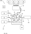
- FIG. 2 shows schematically an embodiment of the analytical system of FIGS. 1A-1F , where the detector 60 is a mass spectrometer connected to the valve-to-detector conduit 30 via an ionization source 61, such as an electrospray ionization (ESI) source, comprising a sprayer capillary 62 that forms part of the valve-to detector conduit 30, being washed with the wash liquid from the wash pump 40.
- an ionization source 61 such as an electrospray ionization (ESI) source, comprising a sprayer capillary 62 that forms part of the valve-to detector conduit 30, being washed with the wash liquid from the wash pump 40.
- ESI electrospray ionization
- FIG. 3 in connection to FIGS. 1A-1F , shows further aspects of the method of FIGS. 1A-1F .
- the method comprise automatically managing by the controller 90 a fluidic-stream connection time, t-Sn-1, t-Sn, t-Sn+1, that is the connection time between each fluidic stream 11, 12, 13 and the valve-to-detector conduit 30 , and a wash-pump connection time, that is the connection time between the wash pump 40 and the valve-to-detector conduit 30, by controlling switching of the stream-selection valve 20.
- the fluidic-stream connection time t-Sn-1, t-Sn, t-Sn+1 is fixed and is the same for each fluidic stream 11, 12, 13.
- the wash-pump connection time t-W is fixed and is a fraction of the fluidic-stream connection time t-Sn-1, t-Sn, t-Sn+1, thereby resulting at least temporarily in a continuous switching at a regular pace.
- the controller 90 is configured to adjust a set of parameters of the detector 60 and/or ionization source 61 from a previous configuration Config. n-1, related to the previous fluidic stream Sn-1 to a subsequent configuration Config. n related to the subsequent fluidic stream Sn, and so on from Config. n to Config. n+1, during the wash-pump connection time t-W before switching to the subsequent fluidic stream.
- controller 90 is configured to control the wash pump 40 to pump wash liquid only during the wash-pump connection time t-W, part of the wash-pump connection time t-W may be needed for starting and stopping the pump action by the wash pump 40, eventually requiring a slightly longer wash-pump connection time t-W in order to compensate for this time lag, while still achieving the same wash effect.
- the controller 90 is configured to control the wash pump 40 to pump wash liquid continuously, while directing wash liquid to waste during the fluidic-stream connection time, the full wash-pump connection time t-W may be used for washing, making possible to eventually reduce the wash-pump connection time t-W while still achieving the same wash effect.
- FIG. 4 which is an adaptation of FIG. 3 , shows another aspect of the analytical system and method, according to which the controller 90 is configured to extend the wash-pump connection time t-W while pumping of wash liquid through the valve-to-detector conduit 30 in case of interrupted switching between fluidic streams or in case of system standby.
- the controller 90 may be configured to control the wash pump 40 to pump wash liquid continuously or at intervals, eventually reducing the flow rate, as long as the valve-to-detector conduit 30 is prevented from drying out.
- FIG. 5 shows an example of the effect that can be achieved by washing between consecutive fluidic streams, under certain conditions.
- FIG. 5 shows two superimposed series of chromatographs obtained by continuously measuring liquid flows out of the valve-to-detector conduit 30 by coupling the valve-to-detector conduit 30 to a mass spectrometer via an ESI source.
- liquid flow from a first fluidic stream S1 is followed directly by liquid flow from a second fluidic stream S2 and again from the first fluidic stream S1.
- the first liquid flow from the first fluidic stream S1 is a continuous infusion of a reference blank solution acetonitrile : water with a volume ratio of 5 : 95, providing a stable and regular background signal.
- the second liquid flow from the second fluidic stream S2 is the same acetonitrile : water solution with a volume ratio of 5 : 95 containing testosterone at a concentration of 50 pg/mL and generating an enhanced and noisy background signal compared to the reference signal.
- the sequence of liquid flows and the solutions used are the same as for series 70, except that a wash liquid W is pumped through the valve-to-detector conduit 30 between S1 and S2, and between S2 and S1.
- the wash liquid used is water : methanol with a volume ratio of 50 : 50, and the wash time or wash-pump connection time t-W is 1.2 seconds, that is a fraction of the fluidic-stream connection time t-S2 of 28.2 seconds for S2 in the second series 80.
- the flow rate of the fluidic streams S 1, S2 is 100 ⁇ L/min whereas the flow rate of the wash liquid is 1 mL/min.
- the fluidic-stream connection time t-S2 for S2 in the first series 70 is longer than in the second series 80, as part of the total time is used for washing in the second series 80.
- t-S2 in the first series 70 is equal to t-S2 + t-W in the second series 80.
- the fluidic-stream connection time for the second t-S1 in the first series 70 is equal to t-S1 + t-W in the second series 80.
- the start of the fluidic-stream connection times t-S2 and t-S 1 are delayed by t-W in the second series 80 versus the first series 70, while their end is the same in the first series 70 and the second series 80.
Landscapes
- Chemical & Material Sciences (AREA)
- Physics & Mathematics (AREA)
- Health & Medical Sciences (AREA)
- Life Sciences & Earth Sciences (AREA)
- Analytical Chemistry (AREA)
- Biochemistry (AREA)
- General Health & Medical Sciences (AREA)
- General Physics & Mathematics (AREA)
- Immunology (AREA)
- Pathology (AREA)
- Dispersion Chemistry (AREA)
- Other Investigation Or Analysis Of Materials By Electrical Means (AREA)
Description
- The present disclosure is related to an analytical system comprising a plurality of fluidic streams alternately connectable to a common detector and to an analytical method comprising switching between fluidic streams.
- There is growing interest for the implementation of mass spectrometry and more specifically of liquid chromatography (LC) coupled to mass spectrometry in the clinical laboratory. However, the lack of standardized and automated procedures and the complexity of the analytical setup limit its implementation.
- Also, typically, a batch approach is followed for processing samples with liquid chromatography-mass spectrometry, where a batch of samples prepared in advance under the same preparation conditions undergo consecutive chromatographic separation runs under the same separation conditions. This approach however does not enable high throughput and is not flexible, e.g., it does not allow for processing of samples in random order as they come. Batch processing also does not allow for re-scheduling (i.e., changing a pre-defined processing sequence) in view for example of incoming emergency samples that have higher priority and have to be processed first.
-
U.S. Patent Application Pub. No. 2018/0292368 A1 describes a system comprising a plurality of LC fluidic streams arranged in parallel and alternately connectable to a mass spectrometer, and a method enabling automated random-access sample preparation and LC separation, thereby making use of LC coupled to mass spectrometry suitable for clinical diagnostics.WO-A1-00/45929 - For high-throughput applications requiring many consecutive sample injection cycles, and especially for random-access analysis of different samples possibly requiring different injection conditions and different LC separation conditions, even more flexibility and speed in quickly changing and adapting the conditions for each sample in a scheduled sequence, can be important.
- In particular, it may be necessary to frequently exchange solvent/eluent used for the LC separations within the same fluidic stream and between parallel fluidic streams. Due to the nature of pump action, to internal dead volumes, and fluidic and surface effects, liquid exchange is a process of repeated dilution of the previously used liquid by the newly used liquid, possibly resulting in long equilibration and signal stabilization times. This process therefore may present a bottleneck if the goal is to achieve high-throughput random-access sample processing, in particular if the goal is to maintain a regular pace of sample injection and analysis regardless of the sample sequence and separation/analysis conditions.
- It is against the above background that the embodiments of the present disclosure provide certain unobvious advantages and advancements over the prior art. In particular, the inventors have recognized a need for improvements in analytical systems and methods for switching between liquid chromatography fluidic streams.
- Although the embodiments of the present disclosure are not limited to specific advantages or functionality, it is noted that the present disclosure provides an analytical system and method, which enable faster and more efficient exchange of the liquid from a previous LC fluidic stream with the liquid of a subsequent LC fluidic stream in the fluidic conduit leading from a stream-selection valve to a detector, thereby resulting in a shorter clearance (signal stabilization) time and hence increased throughput in random-access sample analysis.
- Another advantage of the system and method herein disclosed is minimization of carryover, thus reducing baseline shifts and increasing sensitivity.
- Another advantage of the system and method herein disclosed is that a condition of no flow can be prevented in case of system standby or interrupted liquid chromatography, thereby minimizing surface adsorption effects and contributing to maintain the valve-to-detector conduit cleaner, thus also minimizing maintenance costs and system downtimes.
- Another advantage of the system and method herein disclosed is the enablement of automatic cleaning procedures at convenient times and independently of the liquid chromatography system, hence extending also the lifetime of some system components.
- Another advantage of the system and method herein disclosed may be a standardization of the initial conditions at each fluidic stream switch by, e.g., introducing always the same liquid in between.
- In particular, the analytical system in accordance with one embodiment of the present disclosure comprises a liquid chromatographic system comprising a plurality of fluidic streams alternately connectable to a common detector via a stream-selection valve connected to the detector via a valve-to-detector conduit. The analytical system further comprises a wash pump fluidically connected to the stream-selection valve and configured to connect to the valve-to-detector conduit between two consecutive fluidic streams in order to wash liquid from a previous fluidic stream out of the valve-to-detector conduit before liquid from a subsequent fluidic stream enters the valve-to-detector conduit.
- "Liquid chromatography or LC" is an analytical process that subjects samples injected by a sample injector to chromatographic separation through an LC column in order for example to separate analytes of interest from matrix components, e.g., remaining matrix components after sample preparation that may still interfere with a subsequent detection, e.g., a mass spectrometry detection, and/or in order to separate analytes of interest from each other in order to enable their individual detection. "High-performance liquid chromatography" or HPLC, "ultra-high-performance liquid chromatography" or UHPLC, "micro liquid chromatography" or µLC and "small-bore liquid chromatography" or small-bore LC are forms of liquid chromatography performed under pressure.
- A "liquid chromatographic system or LC system" is an analytical apparatus or module or a unit in an analytical apparatus for carrying out liquid chromatography. The LC system may be embodied as a single channel or as a multi-channel system that may comprise one or a plurality of LC columns arranged in parallel and/or in series. The LC system may also comprise elements such as a sample injector, valves, liquid sources, fluidic connections and parts, e.g., for mixing liquids, degassing liquids, tempering liquids, and the like, one or more sensors, such as pressure sensors, temperature sensors and the like, and especially at least one LC pump. The list is not exhaustive.
- The detector is a mass spectrometer connected to the valve-to-detector conduit via an ionization source. The detector may however be something other than a mass spectrometer, such as, i.e., an optical detector, e.g., a UV or fluorescence detector, an impedance detector, a conductivity detector and the like.
- The LC system is configured as an analytical module designed to prepare a sample for mass spectrometry and/or to transfer a prepared sample to a mass spectrometer, in particular for separating analytes of interest before detection by a mass spectrometer. In particular, typically, during an LC run, the mass spectrometer may be set to scan a specific mass range. LC/MS data can be represented by adding up the ion current in the individual mass scans and plotting that "totaled" ion current as an intensity point against time. The resulting plot looks like an HPLC UV trace with analyte peaks.
- A "fluidic stream" is a fluidic path through which liquids can flow and in particular through which a sample from a sample injection point can be transferred to a detector, e.g., to a mass spectrometer or other detector, and through which the sample may undergo a chromatographic process. The fluidic connection through different parts of the fluidic stream may be discontinuous. This is because the fluidic stream may comprise elements such as switching valves that may establish alternative connections and regulate fluidic flow between different parts of the fluidic stream at different times. The fluidic stream may comprise at least one capillary tubing and/or LC column comprising a stationary phase selected according to the type of sample(s) and analytes of interest, and through which a mobile phase is pumped in order to trap and/or separate and elute and/or transfer analytes of interest under selected conditions, e.g., according to their polarity or log P value, size or affinity, as generally known. The at least one LC column may be exchangeable. In particular, the LC system may comprise more LC columns than fluidic streams, where a plurality of LC columns may be selectable, e.g., interchangeably coupled to the same fluidic stream. Capillary tubing may be also used to bypass LC columns. A fluidic stream may comprise a plurality of substreams.
- In particular, the LC system in accordance with one or more embodiments of the disclosure comprises a plurality of fluidic streams connected to a stream-selection valve for directing flow from one fluidic stream at a time to a detector.
- An "LC column" may refer to any of a column, a cartridge, a capillary and the like for performing separations of a chromatographic nature. Columns are typically packed or loaded with a stationary phase, through which a mobile phase is pumped in order to trap and/or separate and elute and/or transfer analytes of interest under selected conditions, e.g., according to their polarity or log P value, size or affinity, as generally known. This stationary phase can be particulate or beadlike or a porous monolith. However, the term "column" may also refer to capillaries or channels that are not packed or loaded with a stationary phase, but rely on the surface area of the inner capillary wall or geometrical structures to effect separations. An example is provided by pillar array chromatography, where separation beds are formed by etching away interstitial volumes out of a solid silicon wafer, leaving an array of pillars. The resulting channels can be folded onto a small footprint by concatenating bed segments with optimized flow distributors that limit peak dispersion. This creates a stationary phase support structure that is organized in a reproducible, ordered pattern.
- The LC column may be exchangeable and/or operate in parallel or in sequence to one or more other LC columns. An LC column may be for example a rapid trap and elute LC column or "trap-column" for short, a HPLC column or a UHPLC column, and may be of any size, including micro-LC columns and small-bore LC columns, or pillar array LC columns, with an inner diameter of 1 mm or less. In the case of trap-columns, a stationary phase can be selected, which retains analytes of interest, whereas any salts, buffer, detergents and other matrix components are unretained and washed away. This process is typically followed by elution of the analytes, e.g., in back flush mode, with a different mobile phase or a solvent gradient. Depending on the analytes, separation of some analytes can be expected in some cases. On the other hand, in case of analytes having identical masses (isobaric) and/or overlapping daughter ion spectra in multiple reaction monitoring (MRM), when it comes to mass spectrometry, a more extensive chromatographic separation could be typical. In that case, separation in a HPLC or UHPLC column may be advantageous.
- A "liquid chromatography pump or LC pump" is a high-pressure pump that may vary in pressure capacity but that can yield a consistent and reproducible volumetric flow rate though an LC channel. Pressure in HPLC may typically reach as high as 60 MPa or about 600 atmospheres, whereas UHPLC and µ-LC systems have been developed to work at even higher pressures, e.g., up to 140 MPa or about 1400 atmospheres, and therefore are able to use much smaller particle sizes in the LC columns (<2 µm). LC pumps may be configured as binary pumps or even quaternary pumps, e.g., in case of conditions requiring the use of elution gradients by gradually varying the ratio between up to four elution solvents.
- The LC pump can yield a pressure of 60 MPa to 140 MPa, typically 75 MPa to 100 MPa, and more typically 80 MPa.
- The LC pump can be configured to operate with a flow rate between 1 µl/min and 500 µl/min or more, typically up to 1500 µl/min, and more typically operate at flow rates between 100 µl/min to 300 µl/min, and an accuracy of, e.g., about ± 5% or less.
- The LC pump may comprise more than one pump head. For example, binary pumps comprise two pump heads and each pump head typically comprises a primary pump head and a secondary pump head cooperating with each other for pumping liquid while maintaining the liquid pressure inside the pump head about constant. In particular, each of the primary pump head and of the secondary pump head is typically a syringe-like pump comprising a syringe-like cylinder body having an inner wall surface and a plunger translatable through the cylinder body leaving an interspace between the inner wall surface and the plunger when the plunger is translated through the cylinder body.
- The term "liquid" in relation to a fluidic stream refers to liquids commonly used in liquid chromatography, e.g., as solvents or mixtures of solvents used, e.g., as mobile phases or eluents (elution solvents), and as known in the art.
- A "wash pump" is an auxiliary pump distinguished at least in function from the LC pump, the main or sole function being to facilitate and to speed up liquid exchange within the valve-to-detector conduit. In general, the wash pump is a lower-pressure and higher-volume (higherflow-rate) pump compared to the LC pump, and is fluidically connected to the stream-selection valve, independent of the LC system. Typically, the wash pump according to the present disclosure is also a lower-precision pump and hence is also simpler in construction and less expensive in comparison to an LC pump. The wash pump can be a positive-pressure pump. Any pump suitable to generate a positive-pressure in order to actively pump a wash liquid from a wash liquid source through the valve-to-detector conduit via the stream-selection valve, may be used, like for example membrane/diaphragm pumps, single-plunger high-speed pumps, syringe-piston pumps, gear pumps and the like. Positive pressure and active pumping may be achieved by applying pneumatic pressure, e.g., by pressurized gas, e.g., by a nitrogen supply, into a sealed liquid container connected to the upstream inlet valve.
- According to an embodiment, the wash pump is configured to pump a wash liquid through the valve-to-detector conduit at a flow rate higher than that of the fluidic streams, e.g., several times higher, for example, 5 times, 10 times, 20 times or higher. For example, in case of µ-LC with typical flow rates around 1 µL/min, a wash pump flow rate of 5 µL/min may be already beneficial. In case of flow rates of the fluidic streams around 100 µL/min, effective flow rates for the wash pump are around 500 - 1000 µL/min or higher. Flow rates for the wash pump up to 5000 µL/min are possible.
- A "wash liquid" is a liquid suitable to wash out, hence to dissolve, eventual traces of samples in the valve-to-detector conduit while still being compatible with the detector used, e.g., with a mass spectrometer. Therefore, a wash liquid may be the same as or similar to an elution solvent used for chromatography, which depending on the type of samples and analytes may be different. For example, for analytes for which typically reversed-phase chromatography is used, suitable solvents may be organic solvents like methanol, acetonitrile, tetrahydrofuran, and/or isopropylic alcohol. These solvents may be also mixed with each other and/or with water. Acidic or basic additives may be added to adjust the pH. Typical additives can include formic acid, ammonium formate, ammonium acetate, etc. For example, for analytes for which typically normal-phase chromatography is used, suitable solvents may include solvents like hexane, heptane mixed with polar organic solvents such as ethyl acetate, chloroform or 2-propanol.
- The term "valve" refers to a flow-regulating device to control, redirect, restrict or stop flow and, in particular, to an LC switching valve, that is a multi-port valve that controls flow between elements connected to the ports. This is typically achieved by moving one or more valve conduits to switch communication between different elements. Elements may be fluidically connected to the ports via further conduits, like pipes, tubes, capillaries, microfluidic channels and the like, and by fittings like screws/nuts and ferrules, or alternative liquid-tight seals, e.g., maintained in place by a clamp mechanism. An LC switching valve is normally capable of allowing liquid pressures in the order of magnitude used for HPLC or higher.
- In particular, the stream-selection valve may comprise a port for each fluidic stream from the LC system, a port for the valve-to-detector conduit, and a plurality of waste ports.
- The stream-selection valve has an inner valve conduit(s) with an inner diameter of less than 0.6 mm, typically between about 0.5 mm and 0.2 mm, more typically about 0.4 mm, and even more typically about 0.25 mm. The inner valve conduit can have however any other diameter in typically used ranges.
- The stream-selection valve has a typical switching time of about 500 ms or less. The switching time can be however also longer than 500 ms.
- A "mass spectrometer (MS)" is an analytical module comprising a mass analyzer designed to further separate and/or detect analytes based on their mass to charge ratio. The mass spectrometer can be a fast scanning mass spectrometer. The mass spectrometer can be a tandem mass spectrometer capable of selecting parent molecular ions, generating fragments by collision-induced fragmentation, and separating the fragments or daughter ions according to their mass to charge (m/z) ratio. The mass spectrometer can be a triple quadrupole mass spectrometer, as known in the art. Besides quadrupoles, other types of mass analyzers may be used as well, including time of flight, ion trap or combinations thereof.
- An "ionization source (IS)" is an interface coupling LC to MS, configured to generate charged analyte molecules (molecular ions) and transferring the charged analyte molecules from a liquid into a gas phase. The ionization source can be an electro-spray-ionization (ESI) source, or a heated-electrospray-ionization (HESI) source, or an atmospheric-pressure-chemical-ionization (APCI) source, or an atmospheric-pressure-photoionization (APPI) or an atmospheric-pressure-laser-ionization (APLI) source. The LC/MS interface may comprise however a double ionization source, e.g., both an ESI and an APCI source, or a modular exchangeable ionization source.
- Typical parts of an ionization source are a nebulizer and a sampling capillary, typically arranged orthogonally or coaxially with respect to each other. An LC eluate exiting an LC stream is guided through a probe including a sprayer needle or capillary. In this manner, the LC eluate is nebulized in a volume downstream of the sprayer capillary where ionization takes place and the charged analyte molecules thereby obtained are brought into a gaseous phase. A sampling device (e.g., a sampling capillary or orifice) is provided to collect the ions in the gaseous phase and guide them into the mass spectrometer.
- The ionization source may further include an assembly to provide a curtain gas, also known as counter gas, (e.g., N2), which reduces the entry of background ions (e.g., solvent clusters) into the MS. The assembly can have a curtain plate and an orifice assembly for providing the curtain gas. The ionization source may further include an assembly to provide an auxiliary gas, also known as heater gas.
- In order to optimize ionization conditions, it is also possible to adjust solvent composition by adding a make-up flow directly before the ionization source to adjust pH, salts, buffers or organic content.
- Such ionization sources are known in the art and not further elucidated here.
- The ionization source can comprise a sprayer capillary that forms part of the valve-to detector conduit. Thus, liquid from the fluidic streams, including LC eluates, and wash liquid in between fluidic streams alternately flow through the sprayer capillary fluidically connected to the stream-selection valve.
- The analytical system comprises a controller configured to manage a fluidic-stream connection time, that is the connection time between each fluidic stream and the valve-to-detector conduit, and a wash-pump connection time, that is the connection time between the wash pump and the valve-to-detector conduit, by controlling switching of the stream-selection valve. Also, the controller is configured to control the wash pump such that wash liquid is pumped only during the wash-pump connection time.
- As used herein, the term "controller" can mean a processing unit, such as a microprocessor, a microcontroller, a reduced instruction circuit (RISC), an application specific integrated circuit (ASIC), a logic circuit, and any other circuit or processor capable of executing the functions/methods described herein.
- The controller may be integrated into the analytical system or be a separate logic entity in communication with the analytical system via a direct connection, wired or wirelessly, or indirectly over a communications network, wired or wirelessly, such as a wide area network, e.g., the Internet or a Health Care Provider's local area network or intranet, via a network interface device. The processor might be integral with a data management unit, e.g., implemented on a computing device such as a desktop computer, a laptop, a smartphone, a tablet, PDA, etc. It may include a server computer and/or be distributed/shared across/between a plurality of analytical systems. Moreover, the analytical system can include remote devices, servers and cloud-based elements that communicate via wires or wirelessly (e.g., infrared, cellular, Bluetooth®) with the controller, or a remote PC/server or a cloud-based system. The controller may be also configurable to control the analytical system in a way that workflow(s) and workflow step(s) are conducted by the analytical system. In particular, the processor may communicate and/or cooperate with a scheduler and/or a data manager in order to take into account incoming test orders and/or received test orders, and a number of scheduled process operations associated with the execution of the test orders, in combination with managing the fluidic-stream connection time and the wash-pump connection time, controlling switching of the stream-selection valve and action of the wash pump.
- The fluidic-stream connection time can be fixed and is the same for each fluidic stream. In addition, the wash-pump connection time is fixed and is a fraction of the fluidic-stream connection time, thereby resulting at least temporarily in a continuous switching at a regular pace. It may in particular be beneficial if the wash-pump connection time is 20% or less, typically 10% or less, or more typically 5% or less of the fluidic-stream connection time and that the conditions of the wash pump in terms of, e.g., flow rate and/or washing liquid, are so adapted that the wash-pump connection time is minimized. In absolute terms the wash-pump connection time may be as short as a few seconds, typically 5s or less, more typically 3s or less.
- According to the invention as claimed in the appended claims, the controller is configured to adjust a set of parameters of the detector and/or ionization source from a previous configuration related to the previous fluidic stream to a subsequent configuration related to the subsequent fluidic stream during the wash-pump connection time before switching to the subsequent fluidic stream. In this way, by the time the stream-selection valve is switched again, the detector is ready for the subsequent fluidic stream and the fluidic-stream connection time may be in turn also reduced, thereby further increasing throughput. According to an embodiment, the set of parameters can comprise any one or more of a curtain gas pressure, a nebulizer gas pressure, an auxiliary gas pressure, sprayer capillary voltage, sampling capillary voltage and the like, including anything that can be adjusted in advance of starting the detection of an eluate from a fluidic stream.
- The controller can be configured to extend the wash-pump connection time while pumping of wash liquid through the valve-to-detector conduit in case of interrupted switching between fluidic streams or in case of system standby. In case of interrupted switching between fluidic streams or in case of system standby it is otherwise possible that liquid from the last fluidic stream evaporates and the fluidic conduit or part of it, in particular the sprayer capillary, may dry out leading to eventual sample traces or mobile phase additive, e.g., salt, concentration, deposition or even crystallization possibly resulting in clogging and/or strong contamination requiring special maintenance procedure, such as, e.g., replacement of the capillary spray. Considering that an ion source is typically heated, evaporation may happen relatively quickly. The continued use of the wash pump can thus be advantageous in preventing this evaporation by maintaining a continuous liquid flow.
- In accordance with the invention as claimed in the appended claims, an automated analytical method is herein also described, the method comprising alternately connecting a plurality of fluidic streams of a liquid chromatographic (LC) system to a common detector via a stream-selection valve connected to the detector via a valve-to-detector conduit, the method further comprising fluidically connecting a wash pump to the valve-to-detector conduit via the stream-selection valve between two consecutive fluidic streams and washing liquid from a previous fluidic stream out of the valve-to-detector conduit before liquid from a subsequent fluidic stream enters the valve-to-detector conduit.
- The method can further comprise automatically managing a fluidic-stream connection time, that is the connection time between each fluidic stream and the valve-to-detector conduit, and a wash-pump connection time, that is the connection time between the wash pump and the valve-to-detector conduit, by controlling switching of the stream-selection valve.
- The fluidic-stream connection time can be fixed and is the same for each fluidic stream, and wherein the wash-pump connection time is fixed and is a fraction of the fluidic-stream connection time, thereby resulting at least temporarily in a continuous switching at a regular pace.
- The inventive method comprises adjusting a set of parameters of the detector and/or of an ionization source whereby the detector is a mass spectrometer from a previous configuration related to the previous fluidic stream to a subsequent configuration related to the subsequent fluidic stream during the wash-pump connection time before switching to the subsequent fluidic stream.
- The method further comprises extending the wash-pump connection time while pumping of wash liquid through the valve-to-detector conduit in case of interrupted switching between fluidic streams or in case of system standby.
- Other and further objects, features and advantages will appear from the following description of exemplary embodiments in combination with the drawings and the accompanying claims.
- The following detailed description can be best understood when read in conjunction with the following drawings, where like structure is indicated with like reference numerals and in which:
-
FIG. 1A shows schematically an analytical system comprising a wash pump connected to a stream-selection valve and a first step of an analytical method comprising using the wash pump. -
FIG. 1B shows schematically the same analytical system ofFIG. 1A and a second step of the same method. -
FIG. 1C shows schematically the same analytical system ofFIG. 1A and a third step of the same method. -
FIG. 1D shows schematically the same analytical system ofFIG. 1A and a fourth step of the same method, which is identical to that ofFIG. 1B . -
FIG. 1E shows schematically the same analytical system ofFIG. 1A and a fifth step of the same method. -
FIG. 1F shows schematically the same analytical system ofFIG. 1A and a sixth step of the same method, which is identical to that ofFIG. 1B andFIG. 1D . -
FIG. 2 shows schematically further details of the analytical system ofFIGS. 1A-1F related to the detector. -
FIG. 3 shows schematically a method of controlling switching of the stream-selection valve. -
FIG. 4 is a variation of the method ofFIG. 3 including prolonged washing. -
FIG. 5 is an experimental example showing an effect that can be achieved. - Skilled artisans appreciate that elements in the figures are illustrated for simplicity and clarity and have not necessarily been drawn to scale. For example, the dimensions of some of the elements in the figures may be exaggerated relative to other elements to help improve understanding of the embodiments of the present disclosure.
-
FIGS. 1A-1F show a schematic example ofanalytical system 100 comprising a liquid chromatographic (LC)system 10 comprising a plurality offluidic streams common detector 60 via a stream-selection valve 20 connected to thedetector 60 via a valve-to-detector conduit 30. Theanalytical system 100 further comprises awash pump 40 fluidically connected to the stream-selection valve 20 and configured to connect to the valve-to-detector conduit 30 between two consecutive fluidic streams 11,12; 12,13; 13,11 in order to wash liquid from a previous fluidic stream out of the valve-to-detector conduit 30 before liquid from a subsequent fluidic stream enters the valve-to-detector conduit 30. - In particular, the stream-
selection valve 20 comprises in this case a fluidic-stream port fluidic stream fluidic stream waste 50, a wash-pump-inlet port 24 and a wash-pump-waste port 24' leading to thewaste 50. The stream-selection valve 20 comprises in addition a valve-to-detector conduit port 25, connected to the valve-to-detector conduit 30. It is clear that this is only an example and the number of ports and connection may be adapted according to the need and in particular according to the number of fluidic streams. - The
wash pump 40 is connected in this example to four wash liquid containers containingrespective wash liquid washing pump 40 is configured to pump a wash liquid through the valve-to-detector conduit 30 at aflow rate 45 higher than aflow rate 15 of the fluidic streams 11, 12, 13. - The
analytical system 100 further comprises acontroller 90 configured to manage a fluidic-stream connection time, that is the connection time between eachfluidic stream detector conduit 30, and a wash-pump connection time, that is the connection time between thewash pump 40 and the valve-to-detector conduit 30, by controlling switching of the stream-selection valve 20. - With continued reference to
FIGS. 1A-1F , an automated analytical method is also schematically shown, the method comprising alternately connecting a plurality offluidic streams system 10 to acommon detector 60 via a stream-selection valve 20 connected to thedetector 60 via a valve-to-detector conduit 30, the method further comprising fluidically connecting awash pump 40 to the valve-to-detector conduit 30 via the stream-selection valve 20 between two consecutive fluidic streams 11,12; 12,13; 13,11 and washing liquid from a previous fluidic stream out of the valve-to-detector conduit 30 before liquid from a subsequent fluidic stream enters the valve-to-detector conduit 30. - In particular,
FIG. 1A shows a first step of the method in which the stream-selection valve 20 is switched such as thefluidic stream 11 is connected to the valve-to-detector conduit 30, whereas the other fluidic streams 12, 13 are connected to waste ports 22', 23', respectively. Thewash pump 40 is also connected to the respective wash-pump-waste port 24'. -
FIG. 1B shows a second step of the method in which the stream-selection valve 20 is switched such as thewash pump 40 is connected to the valve-to-detector conduit 30, whereas allfluidic streams -
FIG. 1C shows a third step of the method in which the stream-selection valve 20 is switched such as thefluidic stream 12 is connected to the valve-to-detector conduit 30, whereas the other fluidic streams 11, 13 are connected to waste ports 21', 23', respectively. Thewash pump 40 is also connected to the respective wash-pump-waste port 24'. - The fourth step of the method as shown in
FIG. 1D is identical to the second step ofFIG. 1B . -
FIG. 1E shows a fifth step of the method in which the stream-selection valve 20 is switched such as thefluidic stream 13 is connected to the valve-to-detector conduit 30, whereas the other fluidic streams 11, 12 are connected to waste ports 21', 22', respectively. Thewash pump 40 is also connected to the respective wash-pump-waste port 24'. - The sixth step of the method shown in
FIG. 1F is identical to the second step ofFIG. 1B and fourth step ofFIG. 1B , before starting over again with the first step ofFIG. 1A . - With continued reference to
FIGS. 1A-1F , thecontroller 90 may be configured to control thewash pump 40 such that wash liquid is pumped only during the wash-pump connection time, that is only during the second, fourth and sixth steps ofFIGS. 1B , ID, 1F, thereby preventing waste of large volumes of wash liquid, due to the higher flow rate. Thecontroller 90 may be further configured to control the selection and or proportion ofindividual wash liquids - Of course, variations of the method are possible, where a different number of fluidic streams is present and/or where the sequence between fluidic streams may be different. In particular, the method may be adapted to switch between any two or more or all of a plurality of fluidic streams and in any sequence according to the analytical method, as long as the method comprises switching to the wash pump in between two consecutive fluidic streams.
-
FIG. 2 shows schematically an embodiment of the analytical system ofFIGS. 1A-1F , where thedetector 60 is a mass spectrometer connected to the valve-to-detector conduit 30 via anionization source 61, such as an electrospray ionization (ESI) source, comprising asprayer capillary 62 that forms part of the valve-todetector conduit 30, being washed with the wash liquid from thewash pump 40. -
FIG. 3 , in connection toFIGS. 1A-1F , shows further aspects of the method ofFIGS. 1A-1F . - According to one aspect, the method comprise automatically managing by the controller 90 a fluidic-stream connection time, t-Sn-1, t-Sn, t-Sn+1, that is the connection time between each
fluidic stream detector conduit 30 , and a wash-pump connection time, that is the connection time between thewash pump 40 and the valve-to-detector conduit 30, by controlling switching of the stream-selection valve 20. The fluidic-stream connection time t-Sn-1, t-Sn, t-Sn+ 1 is fixed and is the same for eachfluidic stream controller 90 is configured to adjust a set of parameters of thedetector 60 and/orionization source 61 from a previous configuration Config. n-1, related to the previous fluidic stream Sn-1 to a subsequent configuration Config. n related to the subsequent fluidic stream Sn, and so on from Config. n to Config. n+1, during the wash-pump connection time t-W before switching to the subsequent fluidic stream. - In case the
controller 90 is configured to control thewash pump 40 to pump wash liquid only during the wash-pump connection time t-W, part of the wash-pump connection time t-W may be needed for starting and stopping the pump action by thewash pump 40, eventually requiring a slightly longer wash-pump connection time t-W in order to compensate for this time lag, while still achieving the same wash effect. In case thecontroller 90 is configured to control thewash pump 40 to pump wash liquid continuously, while directing wash liquid to waste during the fluidic-stream connection time, the full wash-pump connection time t-W may be used for washing, making possible to eventually reduce the wash-pump connection time t-W while still achieving the same wash effect. -
FIG. 4 , which is an adaptation ofFIG. 3 , shows another aspect of the analytical system and method, according to which thecontroller 90 is configured to extend the wash-pump connection time t-W while pumping of wash liquid through the valve-to-detector conduit 30 in case of interrupted switching between fluidic streams or in case of system standby. Depending on the duration of the interruption or system standby time, thecontroller 90 may be configured to control thewash pump 40 to pump wash liquid continuously or at intervals, eventually reducing the flow rate, as long as the valve-to-detector conduit 30 is prevented from drying out. -
FIG. 5 shows an example of the effect that can be achieved by washing between consecutive fluidic streams, under certain conditions. In particular,FIG. 5 shows two superimposed series of chromatographs obtained by continuously measuring liquid flows out of the valve-to-detector conduit 30 by coupling the valve-to-detector conduit 30 to a mass spectrometer via an ESI source. In thefirst series 70, liquid flow from a first fluidic stream S1 is followed directly by liquid flow from a second fluidic stream S2 and again from the first fluidic stream S1. The first liquid flow from the first fluidic stream S1 is a continuous infusion of a reference blank solution acetonitrile : water with a volume ratio of 5 : 95, providing a stable and regular background signal. The second liquid flow from the second fluidic stream S2 is the same acetonitrile : water solution with a volume ratio of 5 : 95 containing testosterone at a concentration of 50 pg/mL and generating an enhanced and noisy background signal compared to the reference signal. In thesecond series 80, the sequence of liquid flows and the solutions used are the same as forseries 70, except that a wash liquid W is pumped through the valve-to-detector conduit 30 between S1 and S2, and between S2 and S1. The wash liquid used is water : methanol with a volume ratio of 50 : 50, and the wash time or wash-pump connection time t-W is 1.2 seconds, that is a fraction of the fluidic-stream connection time t-S2 of 28.2 seconds for S2 in thesecond series 80. The flow rate of thefluidic streams S 1, S2 is 100 µL/min whereas the flow rate of the wash liquid is 1 mL/min. It is also noted that the fluidic-stream connection time t-S2 for S2 in thefirst series 70 is longer than in thesecond series 80, as part of the total time is used for washing in thesecond series 80. In other words, t-S2 in thefirst series 70 is equal to t-S2 + t-W in thesecond series 80. Also, the fluidic-stream connection time for the second t-S1 in thefirst series 70 is equal to t-S1 + t-W in thesecond series 80. In other words the start of the fluidic-stream connection times t-S2 and t-S 1 are delayed by t-W in thesecond series 80 versus thefirst series 70, while their end is the same in thefirst series 70 and thesecond series 80. - Importantly, it can be observed in
FIG. 5 that when switching from the fluidic stream S2 with an elevated analyte concentration to the fluidic stream S1 with the reference solution, there is a significant difference between thefirst series 70 and thesecond series 80. In particular, in thefirst series 70, it takes a much longer time for the S1 background signal after S2 to return to the same level as for S1 before S2. On the contrary, by introducing the wash step in thesecond series 80 between S2 and S1, the S1 background signal returns at once to the same level as for S1 before S2. Thus the apparent loss of time spent for washing t-W is not only by far compensated but can result in additional time gain due to a much quicker signal stabilization (clearance time). - In the preceding specification, numerous specific details are set forth in order to provide a thorough understanding of the present disclosure. It will be apparent, however, to one having ordinary skill in the art, that the specific detail need not be employed to practice the present teaching. In other instances, well-known materials or methods have not been described in detail in order to avoid obscuring the present disclosure.
Claims (8)
- An analytical system (100) comprising a liquid chromatographic (LC) system (10) comprising a plurality of fluidic streams (11, 12, 13, Sn-1, Sn, Sn+1) alternately connectable to a common detector (60) via a stream-selection valve (20) connected to the detector (60) via a valve-to-detector conduit (30), whereby the detector (60) is a mass spectrometer connected to the valve-to-detector conduit (30) via an ionization source (61) and wherein the analytical system (100) further comprises a wash pump (40) fluidically connected to the stream-selection valve (20) and configured to connect to the valve-to-detector conduit (30) between two consecutive fluidic streams in order to wash liquid from a previous fluidic stream out of the valve-to-detector conduit (30) before liquid from a subsequent fluidic stream enters the valve-to-detector conduit (30), characterized in that the analytical system (100) comprises a controller (90) configured to manage a fluidic-stream connection time (t-Sn-1, t-Sn, t-Sn+1), that is the connection time between each fluidic stream (11, 12, 13, Sn-1, Sn, Sn+1) and the valve-to-detector conduit (30), and a wash-pump connection time (t-W), that is the connection time between the wash pump (40) and the valve-to-detector conduit (30), by controlling switching of the stream-selection valve (20), wherein the controller (90) is configured to adjust a set of parameters of the detector (60) and/or ionization source (61) from a previous configuration related to the previous fluidic stream to a subsequent configuration related to the subsequent fluidic stream during the wash-pump connection time (t-W) before switching to the subsequent fluidic stream, and/or wherein the controller (90) is configured to extend the wash-pump connection time (t-W) while pumping of wash liquid through the valve-to-detector conduit (30) in case of interrupted switching between fluidic streams or in case of system standby.
- The analytical system (100) according to claim 1 wherein the ionization source (61) comprises a sprayer capillary (62) that forms part of the valve-to detector conduit (30).
- The analytical system (100) according to any of the preceding claims wherein the wash pump (40) is configured to pump a wash liquid (41, 42, 43, 44) through the valve-to-detector conduit (30) at a flow rate (45) higher than a flow rate (15) of the fluidic streams 11, 12, 13.
- The analytical system (100) according to any one of the preceding claims wherein the controller (90) is configured to control the wash pump (40) such that wash liquid (41, 42, 43, 44) is pumped only during the wash-pump connection time (t-W).
- The analytical system (100) according to any one of the preceding claims wherein the fluidic-stream connection time (t-Sn-1, t-Sn, t-Sn+1) is fixed and is the same for each fluidic stream (11, 12, 13, Sn-1, Sn, Sn+1) and wherein the wash-pump connection time (t-W) is fixed and is a fraction of the fluidic-stream connection time (t-Sn-1, t-Sn, t-Sn+1), thereby resulting at least temporarily in a continuous switching at a regular pace.
- The analytical system (100) according to any of the preceding claims wherein the set of parameters comprises any one or more of a curtain gas pressure, a nebulizer gas pressure, an auxiliary gas pressure, a sprayer capillary voltage, a sampling capillary voltage.
- An automated analytical method comprising alternately connecting a plurality of fluidic streams (11, 12, 13, Sn-1, Sn, Sn+1) of a liquid chromatographic (LC) system (10) to a common detector (60) via a stream-selection valve (20) connected to the detector (60) via a valve-to-detector conduit (30), the method further comprising fluidically connecting a wash pump (40) to the valve-to-detector conduit (30) via the stream-selection valve (20) between two consecutive fluidic streams and washing liquid from a previous fluidic stream out of the valve-to-detector conduit (30) before liquid from a subsequent fluidic stream enters the valve-to-detector conduit (30), characterized in that the method further comprises automatically managing a fluidic-stream connection time (t-Sn-1, t-Sn, t-Sn+1), that is the connection time between each fluidic stream (11, 12, 13, Sn-1, Sn, Sn+1) and the valve-to-detector conduit (30), and a wash-pump connection time (t-W), that is the connection time between the wash pump (40) and the valve-to-detector conduit (30), by controlling switching of the stream-selection valve (20), wherein the method comprises adjusting a set of parameters of the detector (60) and/or of an ionization source (61) whereby the detector (60) is a mass spectrometer from a previous configuration related to the previous fluidic stream to a subsequent configuration related to the subsequent fluidic stream during the wash-pump connection time (t-W) before switching to the subsequent fluidic stream and/or wherein the method comprises extending the wash-pump connection time (t-W) while pumping of wash liquid through the valve-to-detector conduit (30) in case of interrupted switching between fluidic streams or in case of system standby.
- The method according to claim 7 wherein the fluidic-stream connection time (t-Sn-1, t-Sn, t-Sn+1) is fixed and is the same for each fluidic stream (11, 12, 13, Sn-1, Sn, Sn+1) and wherein the wash-pump connection time (t-W) is fixed and is a fraction of the fluidic-stream connection time (t-Sn-1, t-Sn, t-Sn+1), thereby resulting at least temporarily in a continuous switching at a regular pace.
Priority Applications (5)
| Application Number | Priority Date | Filing Date | Title |
|---|---|---|---|
| EP20169521.0A EP3896443B1 (en) | 2020-04-15 | 2020-04-15 | Analytical system and method including switching between liquid chromatography fluidic streams |
| JP2022562474A JP7506760B2 (en) | 2020-04-15 | 2021-04-12 | Analytical systems and methods involving switching between liquid chromatography fluid streams - Patents.com |
| PCT/EP2021/059412 WO2021209373A1 (en) | 2020-04-15 | 2021-04-12 | Analytical system and method including switching between liquid chromatography fluidic streams |
| CN202180028580.3A CN115398222A (en) | 2020-04-15 | 2021-04-12 | Analytical system and method including switching between liquid chromatography fluid streams |
| US17/965,290 US20230037141A1 (en) | 2020-04-15 | 2022-10-13 | Analytical system and method including switching between liquid chromatography fluidic streams |
Applications Claiming Priority (1)
| Application Number | Priority Date | Filing Date | Title |
|---|---|---|---|
| EP20169521.0A EP3896443B1 (en) | 2020-04-15 | 2020-04-15 | Analytical system and method including switching between liquid chromatography fluidic streams |
Publications (2)
| Publication Number | Publication Date |
|---|---|
| EP3896443A1 EP3896443A1 (en) | 2021-10-20 |
| EP3896443B1 true EP3896443B1 (en) | 2024-05-01 |
Family
ID=70289625
Family Applications (1)
| Application Number | Title | Priority Date | Filing Date |
|---|---|---|---|
| EP20169521.0A Active EP3896443B1 (en) | 2020-04-15 | 2020-04-15 | Analytical system and method including switching between liquid chromatography fluidic streams |
Country Status (5)
| Country | Link |
|---|---|
| US (1) | US20230037141A1 (en) |
| EP (1) | EP3896443B1 (en) |
| JP (1) | JP7506760B2 (en) |
| CN (1) | CN115398222A (en) |
| WO (1) | WO2021209373A1 (en) |
Families Citing this family (3)
| Publication number | Priority date | Publication date | Assignee | Title |
|---|---|---|---|---|
| EP3748354B1 (en) * | 2019-06-04 | 2022-04-06 | F. Hoffmann-La Roche AG | Quick liquid exchange in liquid chromatography |
| JP2023067746A (en) * | 2021-10-29 | 2023-05-16 | 株式会社島津製作所 | Method for cleaning liquid chromatograph system and liquid chromatograph system |
| CN117153659B (en) * | 2023-10-26 | 2023-12-26 | 常州磐诺仪器有限公司 | Auxiliary sample injection device of liquid chromatography mass spectrometer |
Family Cites Families (7)
| Publication number | Priority date | Publication date | Assignee | Title |
|---|---|---|---|---|
| BE636278A (en) * | 1962-08-17 | |||
| US3490202A (en) * | 1968-02-08 | 1970-01-20 | Phillips Petroleum Co | Chromatographic analysis method and apparatus |
| WO2000045929A1 (en) * | 1999-02-08 | 2000-08-10 | Admetric Biochem Inc. | Chromatographic system with pre-detector eluent switching |
| US6812030B2 (en) | 2001-04-25 | 2004-11-02 | Biotrove, Inc. | System and method for high throughput sample preparation and analysis using column chromatography |
| US20050123970A1 (en) * | 2001-04-25 | 2005-06-09 | Can Ozbal | High throughput autosampler |
| JP4613279B2 (en) | 2003-11-07 | 2011-01-12 | バイオシアス ライフ サイエンシーズ, インコーポレイテッド | High-throughput autosampler |
| JP6694509B2 (en) | 2015-12-18 | 2020-05-13 | エフ ホフマン−ラ ロッシュ アクチェン ゲゼルシャフト | Automated clinical diagnostic system and method |
-
2020
- 2020-04-15 EP EP20169521.0A patent/EP3896443B1/en active Active
-
2021
- 2021-04-12 CN CN202180028580.3A patent/CN115398222A/en active Pending
- 2021-04-12 WO PCT/EP2021/059412 patent/WO2021209373A1/en active Application Filing
- 2021-04-12 JP JP2022562474A patent/JP7506760B2/en active Active
-
2022
- 2022-10-13 US US17/965,290 patent/US20230037141A1/en active Pending
Also Published As
| Publication number | Publication date |
|---|---|
| EP3896443A1 (en) | 2021-10-20 |
| JP7506760B2 (en) | 2024-06-26 |
| US20230037141A1 (en) | 2023-02-02 |
| CN115398222A (en) | 2022-11-25 |
| JP2023523548A (en) | 2023-06-06 |
| WO2021209373A1 (en) | 2021-10-21 |
Similar Documents
| Publication | Publication Date | Title |
|---|---|---|
| US20230037141A1 (en) | Analytical system and method including switching between liquid chromatography fluidic streams | |
| EP2217356B1 (en) | Devices and methods for coupling mass spectrometry devices with chromatography systems | |
| EP2963416B1 (en) | A method and system for monitoring biomolecule separations by mass spectrometry | |
| US11385208B2 (en) | Analysis device | |
| US20200064314A1 (en) | Sample injector | |
| EP1685397B1 (en) | High throughput autosampler | |
| US11300548B2 (en) | Liquid chromatography systems | |
| US20220349863A1 (en) | Lc system and method with column backflushing | |
| EP4156228A1 (en) | Analytical system and method | |
| Cai et al. | A straightforward means of coupling preparative high‐performance liquid chromatography and mass spectrometry | |
| US11898997B2 (en) | Sample injector | |
| US11940427B2 (en) | Liquid chromatography—stream equivalence by single stream calibration | |
| Thibodeaux et al. | HPLC-MS/MS for hit generation |
Legal Events
| Date | Code | Title | Description |
|---|---|---|---|
| PUAI | Public reference made under article 153(3) epc to a published international application that has entered the european phase |
Free format text: ORIGINAL CODE: 0009012 |
|
| STAA | Information on the status of an ep patent application or granted ep patent |
Free format text: STATUS: THE APPLICATION HAS BEEN PUBLISHED |
|
| AK | Designated contracting states |
Kind code of ref document: A1 Designated state(s): AL AT BE BG CH CY CZ DE DK EE ES FI FR GB GR HR HU IE IS IT LI LT LU LV MC MK MT NL NO PL PT RO RS SE SI SK SM TR |
|
| B565 | Issuance of search results under rule 164(2) epc |
Effective date: 20201008 |
|
| RAP1 | Party data changed (applicant data changed or rights of an application transferred) |
Owner name: HITACHI HIGH-TECH CORPORATION Owner name: ROCHE DIAGNOSTICS GMBH Owner name: F. HOFFMANN-LA ROCHE AG |
|
| STAA | Information on the status of an ep patent application or granted ep patent |
Free format text: STATUS: REQUEST FOR EXAMINATION WAS MADE |
|
| 17P | Request for examination filed |
Effective date: 20220124 |
|
| RBV | Designated contracting states (corrected) |
Designated state(s): AL AT BE BG CH CY CZ DE DK EE ES FI FR GB GR HR HU IE IS IT LI LT LU LV MC MK MT NL NO PL PT RO RS SE SI SK SM TR |
|
| GRAP | Despatch of communication of intention to grant a patent |
Free format text: ORIGINAL CODE: EPIDOSNIGR1 |
|
| STAA | Information on the status of an ep patent application or granted ep patent |
Free format text: STATUS: GRANT OF PATENT IS INTENDED |
|
| INTG | Intention to grant announced |
Effective date: 20231116 |
|
| GRAS | Grant fee paid |
Free format text: ORIGINAL CODE: EPIDOSNIGR3 |
|
| GRAA | (expected) grant |
Free format text: ORIGINAL CODE: 0009210 |
|
| STAA | Information on the status of an ep patent application or granted ep patent |
Free format text: STATUS: THE PATENT HAS BEEN GRANTED |
|
| RIN1 | Information on inventor provided before grant (corrected) |
Inventor name: HASHIMOTO, YUICHIRO Inventor name: VAN DOORN, AART PIETER Inventor name: TOTH, TIBOR Inventor name: QUINT, STEFAN |
|
| AK | Designated contracting states |
Kind code of ref document: B1 Designated state(s): AL AT BE BG CH CY CZ DE DK EE ES FI FR GB GR HR HU IE IS IT LI LT LU LV MC MK MT NL NO PL PT RO RS SE SI SK SM TR |
|
| REG | Reference to a national code |
Ref country code: GB Ref legal event code: FG4D |
|
| REG | Reference to a national code |
Ref country code: CH Ref legal event code: EP |
|
| REG | Reference to a national code |
Ref country code: IE Ref legal event code: FG4D |
|
| REG | Reference to a national code |
Ref country code: DE Ref legal event code: R096 Ref document number: 602020029926 Country of ref document: DE |
|
| REG | Reference to a national code |
Ref country code: LT Ref legal event code: MG9D |
|
| REG | Reference to a national code |
Ref country code: NL Ref legal event code: MP Effective date: 20240501 |