EP3748261A1 - Method for controlling a heat pump hot-water supply device - Google Patents
Method for controlling a heat pump hot-water supply device Download PDFInfo
- Publication number
- EP3748261A1 EP3748261A1 EP20180416.8A EP20180416A EP3748261A1 EP 3748261 A1 EP3748261 A1 EP 3748261A1 EP 20180416 A EP20180416 A EP 20180416A EP 3748261 A1 EP3748261 A1 EP 3748261A1
- Authority
- EP
- European Patent Office
- Prior art keywords
- refrigerant
- water
- compressor
- temperature
- heat exchanger
- Prior art date
- Legal status (The legal status is an assumption and is not a legal conclusion. Google has not performed a legal analysis and makes no representation as to the accuracy of the status listed.)
- Pending
Links
- XLYOFNOQVPJJNP-UHFFFAOYSA-N water Substances O XLYOFNOQVPJJNP-UHFFFAOYSA-N 0.000 title claims abstract description 238
- 238000000034 method Methods 0.000 title claims abstract description 31
- 239000003507 refrigerant Substances 0.000 claims abstract description 354
- 230000005494 condensation Effects 0.000 claims description 27
- 238000009833 condensation Methods 0.000 claims description 27
- 238000010586 diagram Methods 0.000 description 10
- 239000007788 liquid Substances 0.000 description 10
- 230000015572 biosynthetic process Effects 0.000 description 4
- 230000006835 compression Effects 0.000 description 2
- 238000007906 compression Methods 0.000 description 2
- 230000003247 decreasing effect Effects 0.000 description 2
- 230000003111 delayed effect Effects 0.000 description 2
- 230000008020 evaporation Effects 0.000 description 2
- 238000001704 evaporation Methods 0.000 description 2
- 238000010438 heat treatment Methods 0.000 description 2
- 239000000463 material Substances 0.000 description 2
- 238000005057 refrigeration Methods 0.000 description 2
- 230000000694 effects Effects 0.000 description 1
- 230000003252 repetitive effect Effects 0.000 description 1
- 239000008400 supply water Substances 0.000 description 1
Images


Classifications
-
- F—MECHANICAL ENGINEERING; LIGHTING; HEATING; WEAPONS; BLASTING
- F24—HEATING; RANGES; VENTILATING
- F24H—FLUID HEATERS, e.g. WATER OR AIR HEATERS, HAVING HEAT-GENERATING MEANS, e.g. HEAT PUMPS, IN GENERAL
- F24H15/00—Control of fluid heaters
- F24H15/20—Control of fluid heaters characterised by control inputs
- F24H15/281—Input from user
-
- F—MECHANICAL ENGINEERING; LIGHTING; HEATING; WEAPONS; BLASTING
- F24—HEATING; RANGES; VENTILATING
- F24H—FLUID HEATERS, e.g. WATER OR AIR HEATERS, HAVING HEAT-GENERATING MEANS, e.g. HEAT PUMPS, IN GENERAL
- F24H15/00—Control of fluid heaters
- F24H15/30—Control of fluid heaters characterised by control outputs; characterised by the components to be controlled
- F24H15/305—Control of valves
- F24H15/32—Control of valves of switching valves
-
- F—MECHANICAL ENGINEERING; LIGHTING; HEATING; WEAPONS; BLASTING
- F24—HEATING; RANGES; VENTILATING
- F24H—FLUID HEATERS, e.g. WATER OR AIR HEATERS, HAVING HEAT-GENERATING MEANS, e.g. HEAT PUMPS, IN GENERAL
- F24H4/00—Fluid heaters characterised by the use of heat pumps
- F24H4/02—Water heaters
-
- F—MECHANICAL ENGINEERING; LIGHTING; HEATING; WEAPONS; BLASTING
- F24—HEATING; RANGES; VENTILATING
- F24H—FLUID HEATERS, e.g. WATER OR AIR HEATERS, HAVING HEAT-GENERATING MEANS, e.g. HEAT PUMPS, IN GENERAL
- F24H9/00—Details
- F24H9/20—Arrangement or mounting of control or safety devices
- F24H9/2007—Arrangement or mounting of control or safety devices for water heaters
-
- F—MECHANICAL ENGINEERING; LIGHTING; HEATING; WEAPONS; BLASTING
- F25—REFRIGERATION OR COOLING; COMBINED HEATING AND REFRIGERATION SYSTEMS; HEAT PUMP SYSTEMS; MANUFACTURE OR STORAGE OF ICE; LIQUEFACTION SOLIDIFICATION OF GASES
- F25B—REFRIGERATION MACHINES, PLANTS OR SYSTEMS; COMBINED HEATING AND REFRIGERATION SYSTEMS; HEAT PUMP SYSTEMS
- F25B13/00—Compression machines, plants or systems, with reversible cycle
-
- F—MECHANICAL ENGINEERING; LIGHTING; HEATING; WEAPONS; BLASTING
- F25—REFRIGERATION OR COOLING; COMBINED HEATING AND REFRIGERATION SYSTEMS; HEAT PUMP SYSTEMS; MANUFACTURE OR STORAGE OF ICE; LIQUEFACTION SOLIDIFICATION OF GASES
- F25B—REFRIGERATION MACHINES, PLANTS OR SYSTEMS; COMBINED HEATING AND REFRIGERATION SYSTEMS; HEAT PUMP SYSTEMS
- F25B30/00—Heat pumps
- F25B30/02—Heat pumps of the compression type
-
- F—MECHANICAL ENGINEERING; LIGHTING; HEATING; WEAPONS; BLASTING
- F25—REFRIGERATION OR COOLING; COMBINED HEATING AND REFRIGERATION SYSTEMS; HEAT PUMP SYSTEMS; MANUFACTURE OR STORAGE OF ICE; LIQUEFACTION SOLIDIFICATION OF GASES
- F25B—REFRIGERATION MACHINES, PLANTS OR SYSTEMS; COMBINED HEATING AND REFRIGERATION SYSTEMS; HEAT PUMP SYSTEMS
- F25B49/00—Arrangement or mounting of control or safety devices
- F25B49/02—Arrangement or mounting of control or safety devices for compression type machines, plants or systems
- F25B49/022—Compressor control arrangements
-
- F—MECHANICAL ENGINEERING; LIGHTING; HEATING; WEAPONS; BLASTING
- F28—HEAT EXCHANGE IN GENERAL
- F28D—HEAT-EXCHANGE APPARATUS, NOT PROVIDED FOR IN ANOTHER SUBCLASS, IN WHICH THE HEAT-EXCHANGE MEDIA DO NOT COME INTO DIRECT CONTACT
- F28D9/00—Heat-exchange apparatus having stationary plate-like or laminated conduit assemblies for both heat-exchange media, the media being in contact with different sides of a conduit wall
- F28D9/0093—Multi-circuit heat-exchangers, e.g. integrating different heat exchange sections in the same unit or heat-exchangers for more than two fluids
-
- F—MECHANICAL ENGINEERING; LIGHTING; HEATING; WEAPONS; BLASTING
- F25—REFRIGERATION OR COOLING; COMBINED HEATING AND REFRIGERATION SYSTEMS; HEAT PUMP SYSTEMS; MANUFACTURE OR STORAGE OF ICE; LIQUEFACTION SOLIDIFICATION OF GASES
- F25B—REFRIGERATION MACHINES, PLANTS OR SYSTEMS; COMBINED HEATING AND REFRIGERATION SYSTEMS; HEAT PUMP SYSTEMS
- F25B2339/00—Details of evaporators; Details of condensers
- F25B2339/04—Details of condensers
- F25B2339/047—Water-cooled condensers
-
- F—MECHANICAL ENGINEERING; LIGHTING; HEATING; WEAPONS; BLASTING
- F25—REFRIGERATION OR COOLING; COMBINED HEATING AND REFRIGERATION SYSTEMS; HEAT PUMP SYSTEMS; MANUFACTURE OR STORAGE OF ICE; LIQUEFACTION SOLIDIFICATION OF GASES
- F25B—REFRIGERATION MACHINES, PLANTS OR SYSTEMS; COMBINED HEATING AND REFRIGERATION SYSTEMS; HEAT PUMP SYSTEMS
- F25B2400/00—General features or devices for refrigeration machines, plants or systems, combined heating and refrigeration systems or heat-pump systems, i.e. not limited to a particular subgroup of F25B
- F25B2400/04—Refrigeration circuit bypassing means
- F25B2400/0403—Refrigeration circuit bypassing means for the condenser
-
- F—MECHANICAL ENGINEERING; LIGHTING; HEATING; WEAPONS; BLASTING
- F25—REFRIGERATION OR COOLING; COMBINED HEATING AND REFRIGERATION SYSTEMS; HEAT PUMP SYSTEMS; MANUFACTURE OR STORAGE OF ICE; LIQUEFACTION SOLIDIFICATION OF GASES
- F25B—REFRIGERATION MACHINES, PLANTS OR SYSTEMS; COMBINED HEATING AND REFRIGERATION SYSTEMS; HEAT PUMP SYSTEMS
- F25B2400/00—General features or devices for refrigeration machines, plants or systems, combined heating and refrigeration systems or heat-pump systems, i.e. not limited to a particular subgroup of F25B
- F25B2400/06—Several compression cycles arranged in parallel
- F25B2400/061—Several compression cycles arranged in parallel the capacity of the first system being different from the second
-
- F—MECHANICAL ENGINEERING; LIGHTING; HEATING; WEAPONS; BLASTING
- F25—REFRIGERATION OR COOLING; COMBINED HEATING AND REFRIGERATION SYSTEMS; HEAT PUMP SYSTEMS; MANUFACTURE OR STORAGE OF ICE; LIQUEFACTION SOLIDIFICATION OF GASES
- F25B—REFRIGERATION MACHINES, PLANTS OR SYSTEMS; COMBINED HEATING AND REFRIGERATION SYSTEMS; HEAT PUMP SYSTEMS
- F25B2500/00—Problems to be solved
- F25B2500/31—Low ambient temperatures
-
- F—MECHANICAL ENGINEERING; LIGHTING; HEATING; WEAPONS; BLASTING
- F25—REFRIGERATION OR COOLING; COMBINED HEATING AND REFRIGERATION SYSTEMS; HEAT PUMP SYSTEMS; MANUFACTURE OR STORAGE OF ICE; LIQUEFACTION SOLIDIFICATION OF GASES
- F25B—REFRIGERATION MACHINES, PLANTS OR SYSTEMS; COMBINED HEATING AND REFRIGERATION SYSTEMS; HEAT PUMP SYSTEMS
- F25B2600/00—Control issues
- F25B2600/02—Compressor control
- F25B2600/025—Compressor control by controlling speed
- F25B2600/0251—Compressor control by controlling speed with on-off operation
-
- F—MECHANICAL ENGINEERING; LIGHTING; HEATING; WEAPONS; BLASTING
- F25—REFRIGERATION OR COOLING; COMBINED HEATING AND REFRIGERATION SYSTEMS; HEAT PUMP SYSTEMS; MANUFACTURE OR STORAGE OF ICE; LIQUEFACTION SOLIDIFICATION OF GASES
- F25B—REFRIGERATION MACHINES, PLANTS OR SYSTEMS; COMBINED HEATING AND REFRIGERATION SYSTEMS; HEAT PUMP SYSTEMS
- F25B2600/00—Control issues
- F25B2600/02—Compressor control
- F25B2600/025—Compressor control by controlling speed
- F25B2600/0253—Compressor control by controlling speed with variable speed
-
- F—MECHANICAL ENGINEERING; LIGHTING; HEATING; WEAPONS; BLASTING
- F25—REFRIGERATION OR COOLING; COMBINED HEATING AND REFRIGERATION SYSTEMS; HEAT PUMP SYSTEMS; MANUFACTURE OR STORAGE OF ICE; LIQUEFACTION SOLIDIFICATION OF GASES
- F25B—REFRIGERATION MACHINES, PLANTS OR SYSTEMS; COMBINED HEATING AND REFRIGERATION SYSTEMS; HEAT PUMP SYSTEMS
- F25B2600/00—Control issues
- F25B2600/25—Control of valves
- F25B2600/2501—Bypass valves
-
- F—MECHANICAL ENGINEERING; LIGHTING; HEATING; WEAPONS; BLASTING
- F25—REFRIGERATION OR COOLING; COMBINED HEATING AND REFRIGERATION SYSTEMS; HEAT PUMP SYSTEMS; MANUFACTURE OR STORAGE OF ICE; LIQUEFACTION SOLIDIFICATION OF GASES
- F25B—REFRIGERATION MACHINES, PLANTS OR SYSTEMS; COMBINED HEATING AND REFRIGERATION SYSTEMS; HEAT PUMP SYSTEMS
- F25B2700/00—Sensing or detecting of parameters; Sensors therefor
- F25B2700/21—Temperatures
- F25B2700/2106—Temperatures of fresh outdoor air
-
- F—MECHANICAL ENGINEERING; LIGHTING; HEATING; WEAPONS; BLASTING
- F25—REFRIGERATION OR COOLING; COMBINED HEATING AND REFRIGERATION SYSTEMS; HEAT PUMP SYSTEMS; MANUFACTURE OR STORAGE OF ICE; LIQUEFACTION SOLIDIFICATION OF GASES
- F25B—REFRIGERATION MACHINES, PLANTS OR SYSTEMS; COMBINED HEATING AND REFRIGERATION SYSTEMS; HEAT PUMP SYSTEMS
- F25B2700/00—Sensing or detecting of parameters; Sensors therefor
- F25B2700/21—Temperatures
- F25B2700/2116—Temperatures of a condenser
- F25B2700/21161—Temperatures of a condenser of the fluid heated by the condenser
-
- F—MECHANICAL ENGINEERING; LIGHTING; HEATING; WEAPONS; BLASTING
- F25—REFRIGERATION OR COOLING; COMBINED HEATING AND REFRIGERATION SYSTEMS; HEAT PUMP SYSTEMS; MANUFACTURE OR STORAGE OF ICE; LIQUEFACTION SOLIDIFICATION OF GASES
- F25B—REFRIGERATION MACHINES, PLANTS OR SYSTEMS; COMBINED HEATING AND REFRIGERATION SYSTEMS; HEAT PUMP SYSTEMS
- F25B2700/00—Sensing or detecting of parameters; Sensors therefor
- F25B2700/21—Temperatures
- F25B2700/2116—Temperatures of a condenser
- F25B2700/21163—Temperatures of a condenser of the refrigerant at the outlet of the condenser
-
- F—MECHANICAL ENGINEERING; LIGHTING; HEATING; WEAPONS; BLASTING
- F25—REFRIGERATION OR COOLING; COMBINED HEATING AND REFRIGERATION SYSTEMS; HEAT PUMP SYSTEMS; MANUFACTURE OR STORAGE OF ICE; LIQUEFACTION SOLIDIFICATION OF GASES
- F25B—REFRIGERATION MACHINES, PLANTS OR SYSTEMS; COMBINED HEATING AND REFRIGERATION SYSTEMS; HEAT PUMP SYSTEMS
- F25B7/00—Compression machines, plants or systems, with cascade operation, i.e. with two or more circuits, the heat from the condenser of one circuit being absorbed by the evaporator of the next circuit
-
- F—MECHANICAL ENGINEERING; LIGHTING; HEATING; WEAPONS; BLASTING
- F28—HEAT EXCHANGE IN GENERAL
- F28D—HEAT-EXCHANGE APPARATUS, NOT PROVIDED FOR IN ANOTHER SUBCLASS, IN WHICH THE HEAT-EXCHANGE MEDIA DO NOT COME INTO DIRECT CONTACT
- F28D21/00—Heat-exchange apparatus not covered by any of the groups F28D1/00 - F28D20/00
- F28D2021/0019—Other heat exchangers for particular applications; Heat exchange systems not otherwise provided for
- F28D2021/0068—Other heat exchangers for particular applications; Heat exchange systems not otherwise provided for for refrigerant cycles
- F28D2021/007—Condensers
-
- Y—GENERAL TAGGING OF NEW TECHNOLOGICAL DEVELOPMENTS; GENERAL TAGGING OF CROSS-SECTIONAL TECHNOLOGIES SPANNING OVER SEVERAL SECTIONS OF THE IPC; TECHNICAL SUBJECTS COVERED BY FORMER USPC CROSS-REFERENCE ART COLLECTIONS [XRACs] AND DIGESTS
- Y02—TECHNOLOGIES OR APPLICATIONS FOR MITIGATION OR ADAPTATION AGAINST CLIMATE CHANGE
- Y02B—CLIMATE CHANGE MITIGATION TECHNOLOGIES RELATED TO BUILDINGS, e.g. HOUSING, HOUSE APPLIANCES OR RELATED END-USER APPLICATIONS
- Y02B30/00—Energy efficient heating, ventilation or air conditioning [HVAC]
- Y02B30/12—Hot water central heating systems using heat pumps
-
- Y—GENERAL TAGGING OF NEW TECHNOLOGICAL DEVELOPMENTS; GENERAL TAGGING OF CROSS-SECTIONAL TECHNOLOGIES SPANNING OVER SEVERAL SECTIONS OF THE IPC; TECHNICAL SUBJECTS COVERED BY FORMER USPC CROSS-REFERENCE ART COLLECTIONS [XRACs] AND DIGESTS
- Y02—TECHNOLOGIES OR APPLICATIONS FOR MITIGATION OR ADAPTATION AGAINST CLIMATE CHANGE
- Y02B—CLIMATE CHANGE MITIGATION TECHNOLOGIES RELATED TO BUILDINGS, e.g. HOUSING, HOUSE APPLIANCES OR RELATED END-USER APPLICATIONS
- Y02B30/00—Energy efficient heating, ventilation or air conditioning [HVAC]
- Y02B30/70—Efficient control or regulation technologies, e.g. for control of refrigerant flow, motor or heating
Definitions
- a heat pump hot-water supply device and a method for controlling a heat pump hot-water supply device are disclosed herein.
- heat pump hot-water supply devices are devices that supply hot-water using heat pumps to supply discharge water having a high temperature or to heat indoor floors.
- a refrigeration cycle in which a refrigerant is compressed, condensed, expanded, and evaporated may be driven.
- the heat pump hot-water supply device may be used a lot when outdoor air has a relatively low temperature. Also, according to a range of temperature of the outdoor air, a desired temperature of the discharge water may vary.
- a user may desire to use discharge water having a relatively high temperature.
- a user may desire to use discharge water having a relatively low temperature. That is, a load required for the heat pump hot-water supply device may vary depending on the temperature of the outdoor air.
- Fig. 1 is a schematic diagram of a heat pump hot-water supply device according to an embodiment.
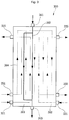
- Fig. 2 is a perspective view of a water-refrigerant heat exchanger according to an embodiment.
- Fig. 3 is a schematic diagram illustrating an inner flow path of the water-refrigerant heat exchanger according to an embodiment.
- a hot water supply device 10 may include a first refrigerant cycle, in which a first refrigerant may circulate, and a second refrigerant cycle, in which a second refrigerant may circulate.
- the first refrigerant cycle may include a first compressor 110 that compresses the first refrigerant, an outdoor heat exchanger 130, and a flow switch 120 that guides the refrigerant compressed in the compressor 110 to the outdoor heat exchanger 130 or a water-refrigerant heat exchanger 300.
- the first compressor 110 may include an inverter compressor in which a frequency is adjustable.
- the refrigerant compressed in the first compressor 110 may flow to the outdoor heat exchanger 130 or the water-refrigerant heat exchanger 300 according to a control state of the flow switch 120.
- the water-refrigerant heat exchanger 300 may be understood as one component of the first refrigerant cycle.
- the first refrigerant cycle may further include a first expansion device 140 that expands the refrigerant condensed in the outdoor heat exchanger 130 or the water-refrigerant heat exchanger 300, and a first gas-liquid separator 105 provided at a suction-side of the first compressor 110 to separate a gaseous refrigerant from the refrigerant.
- the gaseous refrigerant separated by the first gas-liquid separator 105 may be suctioned into the first compressor 110.
- the first expansion device 140 may include an electronic expansion valve (EEV) which is adjustable in opening degree, for example.
- EEV electronic expansion valve
- the first refrigerant cycle has a structure in which the refrigerant compressed in the first compressor 110 is condensed in the water-refrigerant heat exchanger 300 and expanded in the first expansion device 140 and then evaporated in the outdoor heat exchanger 130.
- the refrigerant evaporated in the outdoor heat exchanger 130 may be suctioned again into the first compressor 110 via the first gas-liquid separator 105.
- a fan 135 may be provided adjacent to the outdoor heat exchanger 130.
- the second refrigerant cycle may include a second compressor 210 that compresses a second refrigerant, the water-refrigerant heat exchanger 300 that condenses and evaporates the refrigerant compressed in the second compressor 210, a second expansion device 245 that expands the refrigerant condensed in the water-refrigerant heat exchanger 300, and a second gas-liquid separator 205.
- the second expansion device 245 may include an EEV which is adjustable in opening degree, for example.
- the refrigerant expanded in the second expansion device 245 may be introduced again into the water-refrigerant heat exchanger 300 to heat-exchange with the first and second refrigerants and water supplied thereto. That is, the second refrigerant cycle may further include a guide tube 240 that re-introduces the condensed refrigerant discharged from the water-refrigerant heat exchanger 300 to the water-refrigerant heat exchanger 300.
- the guide tube 240 may extend from a second outflow 335 of the water-refrigerant heat exchanger 300 and be connected to a third inflow 341.
- the second expansion device 245 may be disposed in the guide tube 240.
- the heat pump hot-water supply device 10 may further include a water introduction path 410 connected to the water-refrigerant heat exchanger 300 to supply water, and a water discharge path 420 through which the water heat-exchanged in the water-refrigerant heat exchanger 300 may be discharged.
- a water introduction path 410 connected to the water-refrigerant heat exchanger 300 to supply water
- a water discharge path 420 through which the water heat-exchanged in the water-refrigerant heat exchanger 300 may be discharged.
- the water introduced to the water-refrigerant heat exchanger 300 through the water introduction path 410 may be heated by the first refrigerant or the second refrigerant, and then, may be discharged through the water discharge path 420.
- the heat pump hot-water supply device 10 may further include a bypass tube 250 that guides the condensed second refrigerant so that the second refrigerant may be supplied to the outdoor heat exchanger 130 of the first refrigerant cycle.
- the bypass tube 250 may extend from an outlet-side tube from which the refrigerant condensed in the water-refrigerant heat exchanger 300 is discharged to the outdoor heat exchanger 130.
- the outdoor heat exchanger 130 may include a refrigerant tube through which the first refrigerant may flow and a heat exchange fin coupled to the refrigerant tube to increase a heat exchange area.
- the bypass tube 250 may be provided in at least one refrigerant tube of the outdoor heat exchanger 130, for example, the bypass tube 250 may be provided to contact a lowermost refrigerant tube.
- the second refrigerant having a high temperature flowing through the bypass tube 250 may provide heat to the outdoor heat exchanger 130 to delay or prevent frost formation on the outdoor heat exchanger 130.
- a bypass valve 255 that selectively opens and closes the bypass tube 250 may be provided in the bypass tube 250.
- the bypass valve 255 may include a solenoid valve controlled in an on/off operation.
- an operating pressure range of the first refrigerant cycle may be less than an operating pressure range of the second refrigerant cycle.
- a low pressure of the first refrigerant cycle may be less than a low pressure of the second refrigerant cycle
- a high pressure of the first refrigerant cycle may be less than a high pressure of the second refrigerant cycle (see Fig. 6 ).
- the first refrigerant cycle may be referred to as a "low-stage cycle”
- the second refrigerant cycle may be referred to as a "high-stage cycle”.
- a difference in operating pressure between the first and second refrigerant cycles may occur when the first and second refrigerants are different kinds of refrigerants.
- the first refrigerant may include R410a
- the second refrigerant may include R134a.
- the water-refrigerant heat exchanger 300 may include a plate heat exchanger.
- the water-refrigerant heat exchanger 300 may include a heat exchanger body 301, and a plurality of inflows 321, 331, 341, and 351 and a plurality of outflows 325, 335, 345, and 355 which may be coupled to the heat exchanger body 301.
- the heat exchanger body 301 may include a plurality of plates 310 spaced apart from each other and stacked on each other. Each of the plurality of plates 310 may include a thin plate. A space between the plurality of plates 310 may define a flow path through which the first refrigerant, the second refrigerant, or the water may flow.
- the plurality of inflows 321, 331, 341, and 351 may include a first inflow 321, to which the first refrigerant of the first refrigerant cycle may be introduced (see reference symbol A in ), and second and third refrigerant inflows 331 and 341, to which the second refrigerant of the second refrigerant cycle may be introduced.
- the second and third refrigerant inflows 331 and 341 may include a second inflow 331, to which the refrigerant compressed in the second compressor 210 may be introduced (see reference symbol B in ) and a third inflow 341, to which the refrigerant decompressed in the second expansion device 240 may be introduced (see reference symbol C in ).
- the plurality of inflows 321, 331, 341, and 351 may further include a fourth inflow 351 connected to the water introduction path 410 to guide introduction D in of the supplied water.
- the plurality of outflows 325, 335, 345, and 355 may include a first outflow 325, from which the first refrigerant introduced through the first inflow 321 and heat-exchanged may be discharged (see reference symbol A out ), and second and third refrigerant outflows 335 and 345, from which the second refrigerant may be discharged.
- the second and third refrigerant outflows 335 and 345 may include a second outflow 335, from which the second refrigerant introduced through the second inflow 331 and heat-exchanged may be discharged (see reference symbol Bout), and a third outflow 345, from which the second refrigerant introduced through the third inflow 341 and heat-exchanged may be discharged (see reference symbol C out ).
- the plurality of outflows 325, 335, 345, and 355 may further include a fourth outflow 355 connected to the water discharge path 420 to guide the water heat-exchanged in the water-refrigerant heat exchanger 300 so that the water may be discharged to the water discharge path 420 (see reference symbol D out ).
- the water-refrigerant heat exchanger 300 may include four flow paths heat-exchanged with each other.
- the four flow paths may be defined between the plurality of plates 310, which may be spaced apart from each other.
- the four flow paths may include a first flow path 361 that extends from the first inflow 321 to the first outflow 325 and through which the refrigerant may flow; a second flow path 362 that extends from the second inflow 331 to the second outflow 335 and through which the second refrigerant compressed in the second compressor 210 may flow; and a third flow path 363 that extends from the third inflow 341 to the third outflow 345 and through which the second refrigerant decompressed in the second expansion device 245 may flow; a fourth flow path 364 that extends from the fourth inflow 351 to the fourth outflow 355 and through which the water may flow.
- the first flow path may be referred to as a "first condensation flow path".
- the second refrigerant flowing through the second flow path 362 may be condensed by the first and second refrigerant and the water
- the second flow path may be referred to as a "second condensation flow path”.
- the third flow path 363 may be evaporated by the first and second refrigerants and the water
- the fourth flow path 363 may be referred to as a "water flow path”.
- Each of the first to fourth flow paths 361, 362, 363, and 364 may be divided into a plurality of flow paths or combined with each other.
- the first refrigerant compressed in the first compressor 110 may be introduced to the first flow path 361 in the water-refrigerant heat exchanger 300 through the first inflow 321, and then may be heat-exchanged with the second refrigerant and water flowing through the water-refrigerant heat exchanger 300, that is, heat-exchanged with the second to fourth flow paths 362, 363, and 364, and thus, be condensed.
- the condensed first refrigerant may be discharged from the water-refrigerant heat exchanger 300 through the first outflow 325 and decompressed in the first expansion device 140 and then evaporated in the outdoor heat exchanger 130.
- the evaporated first refrigerant may be suctioned again into the first compressor 110. This cycle may be repeated.
- the second refrigerant compressed in the second compressor 210 may be introduced into the second flow path 362 in the water-refrigerant heat exchanger 300 through the second inflow 331, and then, may be heat-exchanged with the first and second refrigerants and water flowing through the water-refrigerant heat exchanger 300, that is, heat-exchanged with the first, third, and fourth flow paths 361, 363, and 364, and thus, be condensed.
- the condensed second refrigerant may be discharged from the water-refrigerant heat exchanger 300 through the second outflow 335 and decompressed in the second expansion device 245, and then, may be introduced again into the water-refrigerant heat exchanger 300 through the third inflow 341.
- the introduced second refrigerant may flow through the third flow path 363 and be heat-exchanged with the first and second refrigerants and water flowing through the first, second, and fourth flow paths 361, 362, and 364, and thus, be evaporated.
- the evaporated second refrigerant may be suctioned into the second compressor 210. This cycle may be repeated.
- the bypass valve 255 may be opened.
- an opening/closing operation of the bypass valve 255 may be controlled according to a preset or predetermined cycle. According to the opening of the bypass valve 255, at least a portion of the second refrigerant discharged from the second outflow 335 may flow to the bypass tube 250.
- the bypass tube 250 may be divided from the guide tube 240 to extend to the outdoor heat exchanger 130. As the bypass tube 250 contacts the refrigerant tube forming the outdoor heat exchanger 130, heat of the bypass tube 250 may be transferred to the outdoor heat exchanger 130. Thus, the frost formation of the outdoor heat exchanger 130 may be delayed or prevented.
- the supplied water to supply hot-water may be introduced into the water-refrigerant heat exchanger 300 through the water introduction path 410 and the fourth inflow 351.
- the introduced water may be heat-exchanged with the first and second refrigerants flowing through the first to third flow paths 361, 362, and 363, and thus, may be heated.
- the heated water may be discharged through the fourth outflow 355 and the water discharge path 420.
- the discharged water may be stored in a hot-water storage tank, for example.
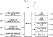
- Fig. 4 is a block diagram of the heat pump hot-water supply device according to an embodiment.
- the heat pump hot-water supply device 10 may include an outdoor air temperature detector 510 that detects a temperature of outdoor air and a controller 500 that determines whether the first refrigerant cycle only operates (a medium temperature operation) or whether the first and second refrigerant cycles simultaneously operate (a high temperature operation) on the basis of the outdoor air temperature recognized or detected by in the outdoor air temperature detector 510.
- the heat pump hot-water supply device 10 may further include a discharge water temperature input 520 that allows a desired temperature of discharge water to be set, and a discharge water temperature detector 530 that detects a temperature of the water actually discharged.
- the discharge water temperature detector 530 may be provided on the fourth outflow 355 or the water discharge path 420.
- the controller 500 may control a frequency of the first compressor 110 or the second compressor 210 on the basis of a preset or predetermined discharge water temperature input through the discharge water temperature input 520 and actual discharge water temperature information recognized in or detected by the discharge water temperature detector 530.
- the controller 500 may increase the frequency of the first compressor 110 or the second compressor 210.
- the controller 500 may maintain or decrease a frequency of the first compressor 110 or the second compressor 210.
- the heat pump hot-water supply device 10 may further include a condensation temperature detector 540 that detects a condensation temperature of the first refrigerant cycle.
- the condensation temperature detector 540 may include a temperature sensor or a pressure sensor.
- the temperature sensor may be provided on or at the first flow path 361, on or at a first outflow part-side to detect a temperature of the first refrigerant passing through the water-refrigerant heat exchanger 300.
- a pressure sensor may be provided on or at an outlet-side tube of the water-refrigerant heat exchanger 300 to detect a high pressure of the first refrigerant cycle.
- a temperature value of the refrigerant may be determined depending on a pressure value.
- the pressure value detected in the pressure sensor may be converted to a condensation temperature value.
- the controller 500 may determine an ability of the first refrigerant cycle on the basis of a first temperature value detected in or by the condensation temperature detector 540 and a second temperature value of the actually discharged water detected in or by the discharge water temperature detector 530. For example, while the first refrigerant cycle operates on the basis of information of the predetermined discharge water temperature and the actual discharge water temperature, when it is detected that the first temperature value is greater than the second temperature value by a preset or predetermined value, it may be recognized that the discharge water temperature is sufficiently increased by only operation of the first refrigerant cycle. Thus, the controller 500 may not command the simultaneous operations of the first and second refrigerant cycles.
- the controller 500 may command the simultaneous operations of the first and second refrigerant cycles.
- Fig. 5 is a flowchart of a method for controlling a heat pump hot-water supply device according to an embodiment.
- a heat pump hot-water supply device 10 may be turned on, and a preset or predetermined discharge water temperature may be input through a discharge water temperature input, such as discharge water temperature input 520 of Fig. 4 .
- a discharge water temperature input such as discharge water temperature input 520 of Fig. 4 .
- an outdoor air temperature may be detected.
- operation S12 it may be determined whether the outdoor air temperature is greater than a preset or predetermined temperature.
- a controller such as controller 500 of Fig. 4 , may control the hot-water supply device to perform a medium temperature operation.
- first compressor such as first compressor 110 of Fig. 1
- first compressor 110 of Fig. 1 may be driven, and the first refrigerant compressed in the first compressor may be introduced into a first inflow, such as first inflow 321 of Fig. 2 , of a water-refrigerant heat exchanger, such as, water-refrigerant heat exchanger 300 of Fig. 2 .
- the first refrigerant introduced into the first inflow may flow through a first flow path, such as first inflow path 361 of Fig. 3 , and may be heat-exchanged with the water flowing through a fourth flow path, such as fourth flow path 364 of Fig. 3 .
- the water may be a medium supplied through a water introduction path, such as water introduction path 410 of Fig. 1 , and a fourth inflow, such as fourth inflow 351 of Fig. 2 , to flow through the water-refrigerant heat exchanger.
- the first refrigerant While the first refrigerant is heat-exchanged with the water, the first refrigerant may be condensed, and the water may be heated. Also, the heated water may be discharged to the outside through a fourth outflow, such as fourth outflow 355 of Fig. 2 , and a water discharge path, such as water discharge path 420 of Fig. 1 .
- the condensed first refrigerant may be discharged from the water-refrigerant heat exchanger through a first outflow, such as first outflow 325 of Fig. 2 , and decompressed in a first expansion device, such as first expansion device 140 of Fig. 1 , and then, may be evaporated in an outdoor heat exchanger, such as outdoor heat exchanger 130 of Fig. 1 .
- the evaporated first refrigerant may be suctioned into the first compressor via a first gas-liquid separator, such as first gas-liquid separator 105 of Fig. 1 .
- this first refrigerant cycle may be repeated.
- a condensation temperature may be detected through or by a condensation temperature detector, such as condensation temperature detector 540 of Fig. 1
- a discharge water temperature may be detected through or by a discharge water temperature detector, such as discharge water temperature detector 530 of Fig. 1 .
- a difference value between the condensation temperature and the discharge water temperature may be determined.
- the condensation temperature may be greater than the discharge water temperature.
- the operation of the first refrigerant cycle may be performed until the discharge water temperature detected in or by the discharge water temperature detector reaches the predetermined discharge water temperature.
- the controller may control an operation frequency of the first compressor on the basis of the difference value between the detected discharge water temperature and the predetermined discharge water temperature.
- an operation frequency of the first compressor when the difference value is greater than a preset or predetermined difference value, an operation frequency of the first compressor may be increased to above a reference frequency.
- the operation frequency of the first compressor when the difference value is less than a preset or predetermined difference value, the operation frequency of the first compressor may be maintained at a reference frequency or may be decreased to less than the reference frequency.
- the reference frequency may be a frequency less than a maximum frequency of the first compressor, which is a predetermined frequency.
- the controller may control the hot-water supply device to perform a high temperature operation.
- first and second refrigerant cycles may simultaneously operate. That is, first and second compressors, such as first and second compressors 110 and 210 of Fig. 1 , may be driven. Also, the first refrigerant compressed in the first compressor may be introduced into the first inflow of the water-refrigerant heat exchanger, and the second refrigerant compressed in the second compressor may be introduced into a second inflow, such as second inflow 331 of Fig. 2 , of the water-refrigerant heat exchanger.
- first and second compressors such as first and second compressors 110 and 210 of Fig. 1
- the first refrigerant compressed in the first compressor may be introduced into the first inflow of the water-refrigerant heat exchanger
- the second refrigerant compressed in the second compressor may be introduced into a second inflow, such as second inflow 331 of Fig. 2 , of the water-refrigerant heat exchanger.
- the first refrigerant introduced into the first inflow may flow through the first flow path and may be heat-exchanged with the second refrigerant and water flowing through second to fourth flow paths, such as second to fourth flow paths 362, 363, and 364 of Fig. 3 .
- the second refrigerant introduced into the second inflow may flow through the second flow path and may be heat-exchanged with the first and second refrigerant and water flowing through the first, third, and fourth flow paths.
- the second refrigerant flowing through the second flow path may be discharged from the water-refrigerant heat exchanger through a second outflow, such as second outflow 335 of Fig. 2 , and expanded in a second expansion device, such as second expansion device 245 of Fig. 1 , while flowing through a guide tube, such as guide tube 240 of Fig. 1 .
- the expanded second refrigerant may be introduced into the water-refrigerant heat exchanger through a third inflow, such as third inflow 341 of Fig. 2 .
- the second refrigerant introduced through the third inflow part may flow through the third flow path and may be heat-exchanged with the first and second refrigerants and water flowing through the first, second, and fourth flow paths.
- the first refrigerant and the second refrigerant of the second flow path may be condensed, and the second refrigerant of the third flow path may be evaporated.
- the water may be heated and discharged to the outside through the fourth outflow and the water discharge path.
- the condensed first refrigerant may be discharged from the water-refrigerant heat exchanger through the first outflow and decompressed in the first expansion device, and then, may be evaporated in the outdoor heat exchanger.
- the evaporated first refrigerant may be suctioned into the first compressor via the first gas-liquid separator. This first refrigerant cycle may be repeated.
- the evaporated second refrigerant may be suctioned into the second compressor via a second gas-liquid separator, such as second gas-liquid separator 205 of Fig. 1 .
- This second refrigerant cycle may be repeated.
- the operation of each of the first and second refrigerant cycles may be performed until the discharge water temperature detected in the discharge water temperature detector reaches the predetermined discharge water temperature.
- the controller may control an operation frequency of each of the first and second compressors on the basis of a difference value between the detected discharge water temperature and the predetermined discharge water temperature.
- an operation frequency of at least one of the first and second compressors may be increased to above a reference frequency.
- the operation frequency of at least one of the first and second compressor may be maintained at a reference frequency or decreased to less than the reference frequency.
- the reference frequency may be a frequency less than a maximum frequency of the first compressor or the second compressor, which is a predetermined frequency.
- the bypass valve may be opened.
- operation S20 according to the opening of the bypass valve, at least a portion of the second refrigerant discharged from the second outflow to flow through the guide tube may flow to the bypass tube, and the refrigerant in the bypass tube may supply heat to the outdoor heat exchanger to delay or prevent frost formation of the outdoor heat exchanger.
- the hot-water supply device As the medium temperature operation or the high temperature operation of the hot-water supply device is determined on the basis of the outdoor air temperature, and even though while the hot-water supply device operates the medium operation, the medium operation is switched to the high temperature operation on the basis of the difference value between the condensation temperature and the discharge water temperature, the hot-water supply device may be improved in operation efficiency.
- Figs. 6A-6B are graphs of a P-H diagram of a refrigerant when the heat pump hot-water supply device operates at a medium temperature and a high temperature, respectively, according to an embodiment.
- Fig. 6A shows a P-H diagram of the first refrigerant cycle when the heat pump hot-water supply device performs a medium temperature operation.
- the first refrigerant circulating in the first refrigerant cycle may be R410a.
- a pressure difference between a low pressure and a high pressure of the first refrigerant cycle may be P ds1 .
- the low pressure of the first refrigerant cycle may represent a suction pressure P s1 of the first compressor 110
- the high pressure of the first refrigerant cycle may represent a discharge pressure P d1 of the first compressor 110.
- the heat pump hot-water supply device 10 performs the medium temperature operation.
- the hot-water supply device 10 When the hot-water supply device 10 performs the medium temperature operation, it may be understood that the first refrigerant forming a low pressure of the first refrigerant cycle absorbs heat Q 1in from the outdoor air passing through the outdoor heat exchanger 130, and the first refrigerant forming a high pressure of the first refrigerant cycle discharges heat Q 1out to the water.
- Fig. 6A shows a P-H diagram of the first and second refrigerant cycles when the heat pump hot-water supply device performs a high temperature operation.
- the first refrigerant circulating in the first refrigerant cycle may be R410a
- the second refrigerant circulating in the second refrigerant cycle may be R134a.
- the heat pump hot-water supply device 10 may form a cascade system.
- a pressure difference between a low pressure and a high pressure of the first and second refrigerant cycles is P ds2 .
- the low pressure of the first and second refrigerant cycles may represent a suction pressure P s2 of the first compressor 110, and the high pressure of the first and second refrigerant cycles may represent a discharge pressure P d2 of the second compressor 210.
- the discharge pressure P d2 is greater than the discharge pressure P d1 .
- the pressure difference P ds2 may be greater than the pressure difference P ds1 .
- the first refrigerant forming the low pressure of the first and second refrigerant cycles absorbs heat Q 2in from the outdoor air passing through the outdoor heat exchanger 130, and the second refrigerant forming the high pressure discharges heat Q 2out to the water.
- the heat pump hot-water supply device may be improved in operation efficiency.
- the first compressor may be only driven to allow the first refrigerant to be heat-exchanged with the supplied water (the medium temperature operation).
- the first and second compressors may be simultaneously driven to allow the first and second refrigerants to be heat-exchanged with the supplied water (the high temperature operation).
- the cycle may be more quickly stabilized when compared to a case in which the first and second compressors are simultaneously driven.
- frost formation of the outdoor heat exchanger may be delayed.
- the water-refrigerant heat exchanger may include a plate heat exchanger, heat exchange efficiency between the first and second refrigerants and the supplied water may be improved.
- Embodiments disclosed herein provide a heat pump hot-water supply device having improved operation efficiency and a method for controlling a heat pump hot-water supply device.
- Embodiments disclosed herein provide a heat pump hot-water supply device that may include a first refrigerant cycle, in which a first refrigerant may circulate, the first refrigerant cycle including a first compressor, an outdoor heat exchanger, and a first expansion device; a second refrigerant cycle, in which a second refrigerant may circulate.
- the second refrigerant cycle may includes a second compressor and a second expansion device.
- the heat pump hot-water supply device may include a water-refrigerant heat exchanger to which the first refrigerant compressed in the first compressor and the second refrigerant compressed in the second compressor may be introduced.
- a water introduction path may be coupled to one or a first side of the water-refrigerant heat exchanger and into which supplied water may be introduced.
- a water discharge path may be coupled to the other or a second side of the water-refrigerant heat exchanger and from which the water heat-exchanged in the refrigerant heat exchanger may be discharged.
- the water-refrigerant heat exchanger may include a first inflow part or inflow that guides introduction of the first refrigerant, and a first outflow part or outflow from which the first refrigerant heat-exchanged in the water-refrigerant heat exchanger may be discharged.
- the water-refrigerant heat exchanger may further include a second inflow part or inflow that guides introduction of the second refrigerant compressed in the second compressor, and a second outflow part or outflow from which the second refrigerant introduced through the second inflow part and heat-exchanged may be discharged.
- the heat pump hot-water supply device may further include a guide tube that allows the refrigerant discharged from the second outflow part to be suctioned again into the water-refrigerant heat exchanger.
- the second expansion device may be disposed on the guide tube.
- the water-refrigerant heat exchanger may further include a third inflow part or inflow connected to the guide tube and to which the second refrigerant may be introduced, and a third outflow part or outflow from which the second refrigerant introduced through the third inflow part and heat-exchanged may be discharged.
- the water-refrigerant heat exchanger may further include a fourth inflow part or inflow connected to the water introduction path to guide introduction of the supplied water, and a fourth outflow part or outflow connected to the water discharge path to allow the water introduced through the fourth inflow part and heat-exchanged to be discharged therefrom.
- the heat pump hot-water supply device may further include a bypass tube divided from the guide tube to extend to the outdoor heat exchanger.
- the heat pump hot-water supply device may also include a bypass valve disposed in or on the bypass tube to allow the second refrigerant flowing through the guide tube to selectively flow to the outdoor heat exchanger.
- the heat pump hot-water supply device may further include an outdoor air temperature detecting part or detector that detects a temperature of outdoor air.
- the heat pump hot-water supply device may further include a controller that controls operation of the first refrigerant cycle and the second refrigerant cycle. A single operation of the first refrigerant cycle or simultaneous operations of the first and second refrigerant cycles may be determined on the basis of whether the outdoor air temperature detected in the outdoor air temperature detecting part is greater than a preset or predetermined temperature.
- the heat pump hot-water supply device may further include a discharge water temperature input that receives input of a desired water temperature from a user; and a discharge water temperature water detector that detects an actual temperature of water discharged from the water-refrigerant heat exchanger.
- the controller may further control a frequency of the first compressor or the second compressor on the basis of an input temperature and the actual temperature.
- the heat pump hot-water supply device may further include a condensation temperature detector that detects a condensation temperature of the first refrigerant cycle.
- the controller may further determine an ability of the first refrigerant cycle by comparing the condensation temperature detected by the condensation temperature detector to the actual temperature of water discharged from the water-refrigerant heat exchanger.
- the first refrigerant cycle may have an operating pressure range that is less than that of the second refrigerant cycle.
- the first refrigerant may include R410a, and the second refrigerant may include R134a.
- Embodiments disclosed herein further provide a method of controlling a heat pump hot-water supply device including a first refrigerant cycle in which a first compressor may be disposed and a second refrigerant cycle in which a second compressor may be disposed.
- the method may include turning on the heat pump hot-water supply device and inputting a preset or predetermined discharge water temperature, and recognizing whether an outdoor air temperature is greater than a preset or predetermined temperature. When the outdoor air temperature is greater than the preset temperature, the first compressor may be singly driven, and when the outdoor air temperature is less than the preset temperature, the first and second compressors may be simultaneously driven.
- the method may further include determining additional driving of the second compressor on the basis of a temperature of water discharged from the water-refrigerant heat exchanger and a condensed temperature of the first refrigerant cycle, while the first compressor is singly driven.
- the method may further include controlling a frequency of the first compressor or the second compressor on the basis of a temperature of water discharged from the water-refrigerant heat exchanger and the preset discharge water temperature.
- Embodiments disclosed herein further provide a heat pump hot-water supply device that may include a first compressor in which a first refrigerant may be compressed; a second compressor in which a second refrigerant may be compressed; a water-refrigerant heat exchanger to which the refrigerant compressed in the first compressor and the refrigerant compressed in the second compressor may be introduced and in which the supplied water may be heat-exchanged with the first and second refrigerants; and a second expansion device disposed at an outlet side of the water-refrigerant heat exchanger to decompress the second refrigerant condensed in the water-refrigerant heat exchanger.
- the water-refrigerant heat exchanger further may include an introduction part to which the second refrigerant decompressed in the expansion device may be introduced.
- the water-refrigerant heat exchanger may include a first condensation flow path through which the first refrigerant may flow; a second condensation flow path through which the second refrigerant compressed in the second compressor may flow; an evaporation flow path through which the second refrigerant decompressed in the expansion device may flow; and a water flow path through which the supplied water may flow.
- the water-refrigerant heat exchanger may further include an outflow part or outflow from which the second refrigerant may be discharge, and a guide tube that extends from the outflow part to the inflow part and on which the expansion device may be disposed.
- the heat pump hot-water supply device may further include a first expansion device that decompresses the first refrigerant condensed in the water-refrigerant heat exchanger, and an outdoor heat exchanger that evaporates the refrigerant decompressed in the first expansion device.
- the heat pump hot-water supply device may further include a bypass tube divided from the guide tube to extend to the outdoor heat exchanger and disposed to contact the outdoor heat exchanger.
- any reference in this specification to "one embodiment,” “an embodiment,” “example embodiment,” etc. means that a particular feature, structure, or characteristic described in connection with the embodiment is included in at least one embodiment.
- the appearances of such phrases in various places in the specification are not necessarily all referring to the same embodiment.
- the present invention is further defined by the following items.
Landscapes
- Engineering & Computer Science (AREA)
- Physics & Mathematics (AREA)
- Mechanical Engineering (AREA)
- Thermal Sciences (AREA)
- General Engineering & Computer Science (AREA)
- Chemical & Material Sciences (AREA)
- Combustion & Propulsion (AREA)
- Heat-Pump Type And Storage Water Heaters (AREA)
- Other Air-Conditioning Systems (AREA)
Abstract
Description
- A heat pump hot-water supply device and a method for controlling a heat pump hot-water supply device are disclosed herein.
- In general, heat pump hot-water supply devices are devices that supply hot-water using heat pumps to supply discharge water having a high temperature or to heat indoor floors. In the heat pump, a refrigeration cycle in which a refrigerant is compressed, condensed, expanded, and evaporated may be driven.
- The heat pump hot-water supply device may be used a lot when outdoor air has a relatively low temperature. Also, according to a range of temperature of the outdoor air, a desired temperature of the discharge water may vary.
- For example, in winter when the temperature of the outdoor air is relatively low, a user may desire to use discharge water having a relatively high temperature. On the other hand, in spring or autumn when the temperature of the outdoor air is relatively high, the user may desire to use discharge water having a relatively low temperature. That is, a load required for the heat pump hot-water supply device may vary depending on the temperature of the outdoor air.
- However, in the heat pump hot-water supply device according to a related art, as a same refrigeration cycle always operates regardless of the temperature of the outdoor air, an operation efficiency of the heat pump hot-water supply device is reduced. A prior art related to the heat pump hot-water supply device is Korean Application No.
KR 10-2010-0010583 - Embodiments will be described in detail with reference to the following drawings in which like reference numerals refer to like elements, and wherein:
-
Fig. 1 is a schematic diagram of a heat pump hot-water supply device according to an embodiment; -
Fig. 2 is a perspective view of a water-refrigerant heat exchanger according to an embodiment; -
Fig. 3 is a schematic diagram illustrating an inner flow path of the water-refrigerant heat exchanger according to an embodiment; -
Fig. 4 is a block diagram of the heat pump hot-water supply device according to an embodiment; -
Fig. 5 is a flowchart of a method for controlling a heat pump hot-water supply device according to an embodiment; and -
Figs. 6A-6B are graphs of a P-H diagram of a refrigerant when the heat pump hot-water supply device operates at a medium temperature and a high temperature, respectively, according to an embodiment. - Reference will now be made in detail to the embodiments, examples of which are illustrated in the accompanying drawings. Where possible, like reference numerals have been used to indicate like elements, and repetitive disclosure has been omitted.
-
Fig. 1 is a schematic diagram of a heat pump hot-water supply device according to an embodiment.Fig. 2 is a perspective view of a water-refrigerant heat exchanger according to an embodiment.Fig. 3 is a schematic diagram illustrating an inner flow path of the water-refrigerant heat exchanger according to an embodiment. - Referring to
Fig. 1 , a hotwater supply device 10 according to an embodiment may include a first refrigerant cycle, in which a first refrigerant may circulate, and a second refrigerant cycle, in which a second refrigerant may circulate. The first refrigerant cycle may include afirst compressor 110 that compresses the first refrigerant, anoutdoor heat exchanger 130, and aflow switch 120 that guides the refrigerant compressed in thecompressor 110 to theoutdoor heat exchanger 130 or a water-refrigerant heat exchanger 300. Thefirst compressor 110 may include an inverter compressor in which a frequency is adjustable. - The refrigerant compressed in the
first compressor 110 may flow to theoutdoor heat exchanger 130 or the water-refrigerant heat exchanger 300 according to a control state of theflow switch 120. The water-refrigerant heat exchanger 300 may be understood as one component of the first refrigerant cycle. - The first refrigerant cycle may further include a
first expansion device 140 that expands the refrigerant condensed in theoutdoor heat exchanger 130 or the water-refrigerant heat exchanger 300, and a first gas-liquid separator 105 provided at a suction-side of thefirst compressor 110 to separate a gaseous refrigerant from the refrigerant. The gaseous refrigerant separated by the first gas-liquid separator 105 may be suctioned into thefirst compressor 110. Thefirst expansion device 140 may include an electronic expansion valve (EEV) which is adjustable in opening degree, for example. - In this embodiment, as a heat pump cycle is driven to supply hot-water, the first refrigerant cycle has a structure in which the refrigerant compressed in the
first compressor 110 is condensed in the water-refrigerant heat exchanger 300 and expanded in thefirst expansion device 140 and then evaporated in theoutdoor heat exchanger 130. The refrigerant evaporated in theoutdoor heat exchanger 130 may be suctioned again into thefirst compressor 110 via the first gas-liquid separator 105. Afan 135 may be provided adjacent to theoutdoor heat exchanger 130. - The second refrigerant cycle may include a
second compressor 210 that compresses a second refrigerant, the water-refrigerant heat exchanger 300 that condenses and evaporates the refrigerant compressed in thesecond compressor 210, asecond expansion device 245 that expands the refrigerant condensed in the water-refrigerant heat exchanger 300, and a second gas-liquid separator 205. Thesecond expansion device 245 may include an EEV which is adjustable in opening degree, for example. - The refrigerant expanded in the
second expansion device 245 may be introduced again into the water-refrigerant heat exchanger 300 to heat-exchange with the first and second refrigerants and water supplied thereto. That is, the second refrigerant cycle may further include aguide tube 240 that re-introduces the condensed refrigerant discharged from the water-refrigerant heat exchanger 300 to the water-refrigerant heat exchanger 300. Theguide tube 240 may extend from asecond outflow 335 of the water-refrigerant heat exchanger 300 and be connected to athird inflow 341. Thesecond expansion device 245 may be disposed in theguide tube 240. - The heat pump hot-
water supply device 10 may further include awater introduction path 410 connected to the water-refrigerant heat exchanger 300 to supply water, and awater discharge path 420 through which the water heat-exchanged in the water-refrigerant heat exchanger 300 may be discharged. For example, the water introduced to the water-refrigerant heat exchanger 300 through thewater introduction path 410 may be heated by the first refrigerant or the second refrigerant, and then, may be discharged through thewater discharge path 420. - The heat pump hot-
water supply device 10 may further include abypass tube 250 that guides the condensed second refrigerant so that the second refrigerant may be supplied to theoutdoor heat exchanger 130 of the first refrigerant cycle. Thebypass tube 250 may extend from an outlet-side tube from which the refrigerant condensed in the water-refrigerant heat exchanger 300 is discharged to theoutdoor heat exchanger 130. - The
outdoor heat exchanger 130 may include a refrigerant tube through which the first refrigerant may flow and a heat exchange fin coupled to the refrigerant tube to increase a heat exchange area. Thebypass tube 250 may be provided in at least one refrigerant tube of theoutdoor heat exchanger 130, for example, thebypass tube 250 may be provided to contact a lowermost refrigerant tube. Thus, the second refrigerant having a high temperature flowing through thebypass tube 250 may provide heat to theoutdoor heat exchanger 130 to delay or prevent frost formation on theoutdoor heat exchanger 130. - A
bypass valve 255 that selectively opens and closes thebypass tube 250 may be provided in thebypass tube 250. For example, thebypass valve 255 may include a solenoid valve controlled in an on/off operation. - When the heat pump hot-
water supply device 10 performs a high temperature operation, that is, when the first and second refrigerant cycles simultaneously operate, an operating pressure range of the first refrigerant cycle may be less than an operating pressure range of the second refrigerant cycle. For example, a low pressure of the first refrigerant cycle may be less than a low pressure of the second refrigerant cycle, and a high pressure of the first refrigerant cycle may be less than a high pressure of the second refrigerant cycle (seeFig. 6 ). Thus, the first refrigerant cycle may be referred to as a "low-stage cycle", and the second refrigerant cycle may be referred to as a "high-stage cycle". - A difference in operating pressure between the first and second refrigerant cycles may occur when the first and second refrigerants are different kinds of refrigerants. For example, the first refrigerant may include R410a, and the second refrigerant may include R134a.
- Referring to
Figs. 2 and3 , the water-refrigerant heat exchanger 300 may include a plate heat exchanger. The water-refrigerant heat exchanger 300 may include aheat exchanger body 301, and a plurality ofinflows outflows heat exchanger body 301. - The
heat exchanger body 301 may include a plurality ofplates 310 spaced apart from each other and stacked on each other. Each of the plurality ofplates 310 may include a thin plate. A space between the plurality ofplates 310 may define a flow path through which the first refrigerant, the second refrigerant, or the water may flow. - The plurality of
inflows first inflow 321, to which the first refrigerant of the first refrigerant cycle may be introduced (see reference symbol Ain), and second andthird refrigerant inflows third refrigerant inflows second inflow 331, to which the refrigerant compressed in thesecond compressor 210 may be introduced (see reference symbol Bin) and athird inflow 341, to which the refrigerant decompressed in thesecond expansion device 240 may be introduced (see reference symbol Cin). The plurality ofinflows fourth inflow 351 connected to thewater introduction path 410 to guide introduction Din of the supplied water. - The plurality of
outflows first outflow 325, from which the first refrigerant introduced through thefirst inflow 321 and heat-exchanged may be discharged (see reference symbol Aout), and second and thirdrefrigerant outflows refrigerant outflows second outflow 335, from which the second refrigerant introduced through thesecond inflow 331 and heat-exchanged may be discharged (see reference symbol Bout), and athird outflow 345, from which the second refrigerant introduced through thethird inflow 341 and heat-exchanged may be discharged (see reference symbol Cout). The plurality ofoutflows fourth outflow 355 connected to thewater discharge path 420 to guide the water heat-exchanged in the water-refrigerant heat exchanger 300 so that the water may be discharged to the water discharge path 420 (see reference symbol Dout). - The water-
refrigerant heat exchanger 300 may include four flow paths heat-exchanged with each other. The four flow paths may be defined between the plurality ofplates 310, which may be spaced apart from each other. The four flow paths may include afirst flow path 361 that extends from thefirst inflow 321 to thefirst outflow 325 and through which the refrigerant may flow; asecond flow path 362 that extends from thesecond inflow 331 to thesecond outflow 335 and through which the second refrigerant compressed in thesecond compressor 210 may flow; and athird flow path 363 that extends from thethird inflow 341 to thethird outflow 345 and through which the second refrigerant decompressed in thesecond expansion device 245 may flow; afourth flow path 364 that extends from thefourth inflow 351 to thefourth outflow 355 and through which the water may flow. - As the first refrigerant flowing through the
first flow path 361 may be condensed by the second refrigerant and the water, the first flow path may be referred to as a "first condensation flow path". As the second refrigerant flowing through thesecond flow path 362 may be condensed by the first and second refrigerant and the water, the second flow path may be referred to as a "second condensation flow path". As the second refrigerant flowing through thethird flow path 363 may be evaporated by the first and second refrigerants and the water, thethird flow path 363 may be referred to as an "evaporation flow path", and thefourth flow path 363 may be referred to as a "water flow path". Each of the first tofourth flow paths - Operations of the heat pump hot-
water supply device 10 according to an embodiment will be described hereinafter. - First, in the first refrigerant cycle, the first refrigerant compressed in the
first compressor 110 may be introduced to thefirst flow path 361 in the water-refrigerant heat exchanger 300 through thefirst inflow 321, and then may be heat-exchanged with the second refrigerant and water flowing through the water-refrigerant heat exchanger 300, that is, heat-exchanged with the second tofourth flow paths refrigerant heat exchanger 300 through thefirst outflow 325 and decompressed in thefirst expansion device 140 and then evaporated in theoutdoor heat exchanger 130. The evaporated first refrigerant may be suctioned again into thefirst compressor 110. This cycle may be repeated. - In the second refrigerant cycle, the second refrigerant compressed in the
second compressor 210 may be introduced into thesecond flow path 362 in the water-refrigerant heat exchanger 300 through thesecond inflow 331, and then, may be heat-exchanged with the first and second refrigerants and water flowing through the water-refrigerant heat exchanger 300, that is, heat-exchanged with the first, third, andfourth flow paths refrigerant heat exchanger 300 through thesecond outflow 335 and decompressed in thesecond expansion device 245, and then, may be introduced again into the water-refrigerant heat exchanger 300 through thethird inflow 341. The introduced second refrigerant may flow through thethird flow path 363 and be heat-exchanged with the first and second refrigerants and water flowing through the first, second, andfourth flow paths second compressor 210. This cycle may be repeated. - When the outdoor temperature is less than a preset or predetermined temperature, frost may form on the
outdoor heat exchanger 130 of the first refrigerant cycle. Thus, in this case, thebypass valve 255 may be opened. For example, an opening/closing operation of thebypass valve 255 may be controlled according to a preset or predetermined cycle. According to the opening of thebypass valve 255, at least a portion of the second refrigerant discharged from thesecond outflow 335 may flow to thebypass tube 250. - The
bypass tube 250 may be divided from theguide tube 240 to extend to theoutdoor heat exchanger 130. As thebypass tube 250 contacts the refrigerant tube forming theoutdoor heat exchanger 130, heat of thebypass tube 250 may be transferred to theoutdoor heat exchanger 130. Thus, the frost formation of theoutdoor heat exchanger 130 may be delayed or prevented. - The supplied water to supply hot-water may be introduced into the water-
refrigerant heat exchanger 300 through thewater introduction path 410 and thefourth inflow 351. The introduced water may be heat-exchanged with the first and second refrigerants flowing through the first tothird flow paths fourth outflow 355 and thewater discharge path 420. The discharged water may be stored in a hot-water storage tank, for example. -
Fig. 4 is a block diagram of the heat pump hot-water supply device according to an embodiment. Referring toFig. 4 , the heat pump hot-water supply device 10 according to an embodiment may include an outdoorair temperature detector 510 that detects a temperature of outdoor air and acontroller 500 that determines whether the first refrigerant cycle only operates (a medium temperature operation) or whether the first and second refrigerant cycles simultaneously operate (a high temperature operation) on the basis of the outdoor air temperature recognized or detected by in the outdoorair temperature detector 510. - The heat pump hot-
water supply device 10 may further include a dischargewater temperature input 520 that allows a desired temperature of discharge water to be set, and a dischargewater temperature detector 530 that detects a temperature of the water actually discharged. The dischargewater temperature detector 530 may be provided on thefourth outflow 355 or thewater discharge path 420. - The
controller 500 may control a frequency of thefirst compressor 110 or thesecond compressor 210 on the basis of a preset or predetermined discharge water temperature input through the dischargewater temperature input 520 and actual discharge water temperature information recognized in or detected by the dischargewater temperature detector 530. - For example, when the actual discharge water temperature is less than the predetermined discharge water temperature, the
controller 500 may increase the frequency of thefirst compressor 110 or thesecond compressor 210. On the other hand, when the actual discharge water temperature reaches or is greater than the predetermined discharge water temperature, thecontroller 500 may maintain or decrease a frequency of thefirst compressor 110 or thesecond compressor 210. - The heat pump hot-
water supply device 10 may further include acondensation temperature detector 540 that detects a condensation temperature of the first refrigerant cycle. Thecondensation temperature detector 540 may include a temperature sensor or a pressure sensor. - For example, the temperature sensor may be provided on or at the
first flow path 361, on or at a first outflow part-side to detect a temperature of the first refrigerant passing through the water-refrigerant heat exchanger 300. A pressure sensor may be provided on or at an outlet-side tube of the water-refrigerant heat exchanger 300 to detect a high pressure of the first refrigerant cycle. When the refrigerant is in a liquid state or in a two-phase state, a temperature value of the refrigerant may be determined depending on a pressure value. Thus, the pressure value detected in the pressure sensor may be converted to a condensation temperature value. - The
controller 500 may determine an ability of the first refrigerant cycle on the basis of a first temperature value detected in or by thecondensation temperature detector 540 and a second temperature value of the actually discharged water detected in or by the dischargewater temperature detector 530. For example, while the first refrigerant cycle operates on the basis of information of the predetermined discharge water temperature and the actual discharge water temperature, when it is detected that the first temperature value is greater than the second temperature value by a preset or predetermined value, it may be recognized that the discharge water temperature is sufficiently increased by only operation of the first refrigerant cycle. Thus, thecontroller 500 may not command the simultaneous operations of the first and second refrigerant cycles. - On the other hand, when it is detected that the first temperature value is not greater than that the second temperature value by a preset or predetermined value, it may be recognized that the discharge water temperature is not sufficiently increased by only the operation of the first refrigerant cycle. Thus, the
controller 500 may command the simultaneous operations of the first and second refrigerant cycles. -
Fig. 5 is a flowchart of a method for controlling a heat pump hot-water supply device according to an embodiment. Referring toFig. 5 , in operation S11, a heat pump hot-water supply device 10 may be turned on, and a preset or predetermined discharge water temperature may be input through a discharge water temperature input, such as dischargewater temperature input 520 ofFig. 4 . In operation S12, an outdoor air temperature may be detected. - In operation S12, it may be determined whether the outdoor air temperature is greater than a preset or predetermined temperature. When the outdoor air temperature is greater than the predetermined temperature, that is, when the outdoor air temperature is relatively high, it is less necessary to generate discharge water having a high temperature, and thus, a controller, such as
controller 500 ofFig. 4 , may control the hot-water supply device to perform a medium temperature operation. - When the hot-water supply device performs the medium temperature operation, only the first refrigerant cycle may operate. That is, a first compressor, such as
first compressor 110 ofFig. 1 , may be driven, and the first refrigerant compressed in the first compressor may be introduced into a first inflow, such asfirst inflow 321 ofFig. 2 , of a water-refrigerant heat exchanger, such as, water-refrigerant heat exchanger 300 ofFig. 2 . - The first refrigerant introduced into the first inflow may flow through a first flow path, such as
first inflow path 361 ofFig. 3 , and may be heat-exchanged with the water flowing through a fourth flow path, such asfourth flow path 364 ofFig. 3 . The water may be a medium supplied through a water introduction path, such aswater introduction path 410 ofFig. 1 , and a fourth inflow, such asfourth inflow 351 ofFig. 2 , to flow through the water-refrigerant heat exchanger. - While the first refrigerant is heat-exchanged with the water, the first refrigerant may be condensed, and the water may be heated. Also, the heated water may be discharged to the outside through a fourth outflow, such as
fourth outflow 355 ofFig. 2 , and a water discharge path, such aswater discharge path 420 ofFig. 1 . - The condensed first refrigerant may be discharged from the water-refrigerant heat exchanger through a first outflow, such as
first outflow 325 ofFig. 2 , and decompressed in a first expansion device, such asfirst expansion device 140 ofFig. 1 , and then, may be evaporated in an outdoor heat exchanger, such asoutdoor heat exchanger 130 ofFig. 1 . The evaporated first refrigerant may be suctioned into the first compressor via a first gas-liquid separator, such as first gas-liquid separator 105 ofFig. 1 . In operation S14, this first refrigerant cycle may be repeated. - In operation S15, while the first refrigerant cycle operates, a condensation temperature may be detected through or by a condensation temperature detector, such as
condensation temperature detector 540 ofFig. 1 , and a discharge water temperature may be detected through or by a discharge water temperature detector, such as dischargewater temperature detector 530 ofFig. 1 . A difference value between the condensation temperature and the discharge water temperature may be determined. The condensation temperature may be greater than the discharge water temperature. When the difference value is greater than a preset or predetermined value, as it may be recognized that the supplied water is heated only by the operation of the first refrigerant cycle, and the first refrigerant cycle may continuously operate. - The operation of the first refrigerant cycle may be performed until the discharge water temperature detected in or by the discharge water temperature detector reaches the predetermined discharge water temperature. The controller may control an operation frequency of the first compressor on the basis of the difference value between the detected discharge water temperature and the predetermined discharge water temperature.
- For example, in operations S16 and S17, when the difference value is greater than a preset or predetermined difference value, an operation frequency of the first compressor may be increased to above a reference frequency. On the other hand, when the difference value is less than a preset or predetermined difference value, the operation frequency of the first compressor may be maintained at a reference frequency or may be decreased to less than the reference frequency. The reference frequency may be a frequency less than a maximum frequency of the first compressor, which is a predetermined frequency.
- In operation S13, when the outdoor air temperature is less than a preset or predetermined temperature, that is, when the outdoor air temperature is relatively low, it is more necessary to generate discharge water having a high temperature, and thus, the controller may control the hot-water supply device to perform a high temperature operation.
- When the hot-water supply device performs the high temperature operation, the first and second refrigerant cycles may simultaneously operate. That is, first and second compressors, such as first and
second compressors Fig. 1 , may be driven. Also, the first refrigerant compressed in the first compressor may be introduced into the first inflow of the water-refrigerant heat exchanger, and the second refrigerant compressed in the second compressor may be introduced into a second inflow, such assecond inflow 331 ofFig. 2 , of the water-refrigerant heat exchanger. - The first refrigerant introduced into the first inflow may flow through the first flow path and may be heat-exchanged with the second refrigerant and water flowing through second to fourth flow paths, such as second to
fourth flow paths Fig. 3 . The second refrigerant introduced into the second inflow may flow through the second flow path and may be heat-exchanged with the first and second refrigerant and water flowing through the first, third, and fourth flow paths. - The second refrigerant flowing through the second flow path may be discharged from the water-refrigerant heat exchanger through a second outflow, such as
second outflow 335 ofFig. 2 , and expanded in a second expansion device, such assecond expansion device 245 ofFig. 1 , while flowing through a guide tube, such asguide tube 240 ofFig. 1 . The expanded second refrigerant may be introduced into the water-refrigerant heat exchanger through a third inflow, such asthird inflow 341 ofFig. 2 . - The second refrigerant introduced through the third inflow part may flow through the third flow path and may be heat-exchanged with the first and second refrigerants and water flowing through the first, second, and fourth flow paths.
- In the water-refrigerant heat exchanger, while the first to fourth flow paths are heat-exchanged with each other, the first refrigerant and the second refrigerant of the second flow path may be condensed, and the second refrigerant of the third flow path may be evaporated. The water may be heated and discharged to the outside through the fourth outflow and the water discharge path.
- The condensed first refrigerant may be discharged from the water-refrigerant heat exchanger through the first outflow and decompressed in the first expansion device, and then, may be evaporated in the outdoor heat exchanger. The evaporated first refrigerant may be suctioned into the first compressor via the first gas-liquid separator. This first refrigerant cycle may be repeated.
- Also, in operations S18 and S19, the evaporated second refrigerant may be suctioned into the second compressor via a second gas-liquid separator, such as second gas-
liquid separator 205 ofFig. 1 . This second refrigerant cycle may be repeated. - The operation of each of the first and second refrigerant cycles may be performed until the discharge water temperature detected in the discharge water temperature detector reaches the predetermined discharge water temperature. The controller may control an operation frequency of each of the first and second compressors on the basis of a difference value between the detected discharge water temperature and the predetermined discharge water temperature.
- For example, when the difference value is greater than a preset or predetermined difference value, an operation frequency of at least one of the first and second compressors may be increased to above a reference frequency. On the other hand, when the difference value is less than a preset or predetermined difference value, the operation frequency of at least one of the first and second compressor may be maintained at a reference frequency or decreased to less than the reference frequency. The reference frequency may be a frequency less than a maximum frequency of the first compressor or the second compressor, which is a predetermined frequency.
- Also, depending on a preset or predetermined cycle, the bypass valve may be opened. In operation S20, according to the opening of the bypass valve, at least a portion of the second refrigerant discharged from the second outflow to flow through the guide tube may flow to the bypass tube, and the refrigerant in the bypass tube may supply heat to the outdoor heat exchanger to delay or prevent frost formation of the outdoor heat exchanger.
- In operation S16, when the difference between the condensation temperature and the discharge water temperature is less than a preset or predetermined value, it may be recognized that heating of the supplied water is restricted by only the operation of the first refrigerant cycle. Thus, an additional operation of the second refrigerant cycle, that is, high temperature operation of the hot-water supply device before the operation S18 may be performed.
- As the medium temperature operation or the high temperature operation of the hot-water supply device is determined on the basis of the outdoor air temperature, and even though while the hot-water supply device operates the medium operation, the medium operation is switched to the high temperature operation on the basis of the difference value between the condensation temperature and the discharge water temperature, the hot-water supply device may be improved in operation efficiency.
-
Figs. 6A-6B are graphs of a P-H diagram of a refrigerant when the heat pump hot-water supply device operates at a medium temperature and a high temperature, respectively, according to an embodiment.Fig. 6A shows a P-H diagram of the first refrigerant cycle when the heat pump hot-water supply device performs a medium temperature operation. For example, the first refrigerant circulating in the first refrigerant cycle may be R410a. A pressure difference between a low pressure and a high pressure of the first refrigerant cycle may be Pds1. The low pressure of the first refrigerant cycle may represent a suction pressure Ps1 of thefirst compressor 110, and the high pressure of the first refrigerant cycle may represent a discharge pressure Pd1 of thefirst compressor 110. - In consideration of a material property of R410a, it is difficult for the discharge pressure Pd1 to have a sufficiently high pressure. Also, in consideration of a compression ratio of the
first compressor 110, it is difficult for the pressure difference Pds1 to have a sufficiently high value. Thus, when the first refrigerant cycle only operates, the heat pump hot-water supply device 10 performs the medium temperature operation. - When the hot-
water supply device 10 performs the medium temperature operation, it may be understood that the first refrigerant forming a low pressure of the first refrigerant cycle absorbs heat Q1in from the outdoor air passing through theoutdoor heat exchanger 130, and the first refrigerant forming a high pressure of the first refrigerant cycle discharges heat Q1out to the water. - On the other hand,
Fig. 6A shows a P-H diagram of the first and second refrigerant cycles when the heat pump hot-water supply device performs a high temperature operation. For example, the first refrigerant circulating in the first refrigerant cycle may be R410a, and the second refrigerant circulating in the second refrigerant cycle may be R134a. - According to the combination of the two refrigerant cycles, the heat pump hot-
water supply device 10 may form a cascade system. A pressure difference between a low pressure and a high pressure of the first and second refrigerant cycles is Pds2. - The low pressure of the first and second refrigerant cycles may represent a suction pressure Ps2 of the
first compressor 110, and the high pressure of the first and second refrigerant cycles may represent a discharge pressure Pd2 of thesecond compressor 210. - In consideration of a material property of R134a, the discharge pressure Pd2 is greater than the discharge pressure Pd1. Also, in consideration of the combined compression ratio of the first and
second compressors water supply device 10 may perform the high temperature operation. - When the hot-
water supply device 10 performs the high temperature operation, it may be understood that the first refrigerant forming the low pressure of the first and second refrigerant cycles absorbs heat Q2in from the outdoor air passing through theoutdoor heat exchanger 130, and the second refrigerant forming the high pressure discharges heat Q2out to the water. - According to components and operations of the above-described heat pump hot-
water supply device 10, system efficiency may be improved. - According to embodiments disclosed herein, as the medium temperature operation and the high temperature operation of the heat pump hot-water supply device is selectively performed according to the outdoor air temperature, the heat pump hot-water supply device may be improved in operation efficiency. When the outdoor air temperature is greater than the predetermined temperature, as the desired temperature of the discharge water is low, and the device has a relatively low operation load, the first compressor may be only driven to allow the first refrigerant to be heat-exchanged with the supplied water (the medium temperature operation). On the other hand, when the outdoor air temperature is less than the predetermined temperature, as the desired temperature of the discharge water is high, and the device has a relatively high operation load, the first and second compressors may be simultaneously driven to allow the first and second refrigerants to be heat-exchanged with the supplied water (the high temperature operation).
- Further, when the medium temperature operation is performed, as the first compressor is only driven to operate the cycle, the cycle may be more quickly stabilized when compared to a case in which the first and second compressors are simultaneously driven. Furthermore, when the high temperature operation is performed, as the refrigerant condensed in the second refrigerant cycle is supplied to the outdoor heat exchanger of the first refrigerant cycle, frost formation of the outdoor heat exchanger may be delayed. Also, as the water-refrigerant heat exchanger may include a plate heat exchanger, heat exchange efficiency between the first and second refrigerants and the supplied water may be improved.
- Embodiments disclosed herein provide a heat pump hot-water supply device having improved operation efficiency and a method for controlling a heat pump hot-water supply device.
- Embodiments disclosed herein provide a heat pump hot-water supply device that may include a first refrigerant cycle, in which a first refrigerant may circulate, the first refrigerant cycle including a first compressor, an outdoor heat exchanger, and a first expansion device; a second refrigerant cycle, in which a second refrigerant may circulate. The second refrigerant cycle may includes a second compressor and a second expansion device. The heat pump hot-water supply device may include a water-refrigerant heat exchanger to which the first refrigerant compressed in the first compressor and the second refrigerant compressed in the second compressor may be introduced. A water introduction path may be coupled to one or a first side of the water-refrigerant heat exchanger and into which supplied water may be introduced. A water discharge path may be coupled to the other or a second side of the water-refrigerant heat exchanger and from which the water heat-exchanged in the refrigerant heat exchanger may be discharged.
- The water-refrigerant heat exchanger may include a first inflow part or inflow that guides introduction of the first refrigerant, and a first outflow part or outflow from which the first refrigerant heat-exchanged in the water-refrigerant heat exchanger may be discharged.
- The water-refrigerant heat exchanger may further include a second inflow part or inflow that guides introduction of the second refrigerant compressed in the second compressor, and a second outflow part or outflow from which the second refrigerant introduced through the second inflow part and heat-exchanged may be discharged.
- The heat pump hot-water supply device may further include a guide tube that allows the refrigerant discharged from the second outflow part to be suctioned again into the water-refrigerant heat exchanger. The second expansion device may be disposed on the guide tube.
- The water-refrigerant heat exchanger may further include a third inflow part or inflow connected to the guide tube and to which the second refrigerant may be introduced, and a third outflow part or outflow from which the second refrigerant introduced through the third inflow part and heat-exchanged may be discharged.
- The water-refrigerant heat exchanger may further include a fourth inflow part or inflow connected to the water introduction path to guide introduction of the supplied water, and a fourth outflow part or outflow connected to the water discharge path to allow the water introduced through the fourth inflow part and heat-exchanged to be discharged therefrom.
- The heat pump hot-water supply device may further include a bypass tube divided from the guide tube to extend to the outdoor heat exchanger. The heat pump hot-water supply device may also include a bypass valve disposed in or on the bypass tube to allow the second refrigerant flowing through the guide tube to selectively flow to the outdoor heat exchanger.
- The heat pump hot-water supply device may further include an outdoor air temperature detecting part or detector that detects a temperature of outdoor air. The heat pump hot-water supply device may further include a controller that controls operation of the first refrigerant cycle and the second refrigerant cycle. A single operation of the first refrigerant cycle or simultaneous operations of the first and second refrigerant cycles may be determined on the basis of whether the outdoor air temperature detected in the outdoor air temperature detecting part is greater than a preset or predetermined temperature.
- The heat pump hot-water supply device may further include a discharge water temperature input that receives input of a desired water temperature from a user; and a discharge water temperature water detector that detects an actual temperature of water discharged from the water-refrigerant heat exchanger. The controller may further control a frequency of the first compressor or the second compressor on the basis of an input temperature and the actual temperature.
- The heat pump hot-water supply device may further include a condensation temperature detector that detects a condensation temperature of the first refrigerant cycle. The controller may further determine an ability of the first refrigerant cycle by comparing the condensation temperature detected by the condensation temperature detector to the actual temperature of water discharged from the water-refrigerant heat exchanger.
- The first refrigerant cycle may have an operating pressure range that is less than that of the second refrigerant cycle. The first refrigerant may include R410a, and the second refrigerant may include R134a.
- Embodiments disclosed herein further provide a method of controlling a heat pump hot-water supply device including a first refrigerant cycle in which a first compressor may be disposed and a second refrigerant cycle in which a second compressor may be disposed. The method may include turning on the heat pump hot-water supply device and inputting a preset or predetermined discharge water temperature, and recognizing whether an outdoor air temperature is greater than a preset or predetermined temperature. When the outdoor air temperature is greater than the preset temperature, the first compressor may be singly driven, and when the outdoor air temperature is less than the preset temperature, the first and second compressors may be simultaneously driven.
- The method may further include determining additional driving of the second compressor on the basis of a temperature of water discharged from the water-refrigerant heat exchanger and a condensed temperature of the first refrigerant cycle, while the first compressor is singly driven.
- The method may further include controlling a frequency of the first compressor or the second compressor on the basis of a temperature of water discharged from the water-refrigerant heat exchanger and the preset discharge water temperature.
- Embodiments disclosed herein further provide a heat pump hot-water supply device that may include a first compressor in which a first refrigerant may be compressed; a second compressor in which a second refrigerant may be compressed; a water-refrigerant heat exchanger to which the refrigerant compressed in the first compressor and the refrigerant compressed in the second compressor may be introduced and in which the supplied water may be heat-exchanged with the first and second refrigerants; and a second expansion device disposed at an outlet side of the water-refrigerant heat exchanger to decompress the second refrigerant condensed in the water-refrigerant heat exchanger. The water-refrigerant heat exchanger further may include an introduction part to which the second refrigerant decompressed in the expansion device may be introduced.
- The water-refrigerant heat exchanger may include a first condensation flow path through which the first refrigerant may flow; a second condensation flow path through which the second refrigerant compressed in the second compressor may flow; an evaporation flow path through which the second refrigerant decompressed in the expansion device may flow; and a water flow path through which the supplied water may flow. The water-refrigerant heat exchanger may further include an outflow part or outflow from which the second refrigerant may be discharge, and a guide tube that extends from the outflow part to the inflow part and on which the expansion device may be disposed.
- The heat pump hot-water supply device may further include a first expansion device that decompresses the first refrigerant condensed in the water-refrigerant heat exchanger, and an outdoor heat exchanger that evaporates the refrigerant decompressed in the first expansion device. The heat pump hot-water supply device may further include a bypass tube divided from the guide tube to extend to the outdoor heat exchanger and disposed to contact the outdoor heat exchanger.
- Any reference in this specification to "one embodiment," "an embodiment," "example embodiment," etc., means that a particular feature, structure, or characteristic described in connection with the embodiment is included in at least one embodiment. The appearances of such phrases in various places in the specification are not necessarily all referring to the same embodiment. Further, when a particular feature, structure, or characteristic is described in connection with any embodiment, it is submitted that it is within the purview of one skilled in the art to effect such feature, structure, or characteristic in connection with other ones of the embodiments.
- The present invention is further defined by the following items.
- 1. A heat pump hot-water supply device (10), comprising:
- a first refrigerant cycle, in which a first refrigerant circulates, and including a first compressor (110), an outdoor heat exchanger (130), and a first expansion device (140);
- a second refrigerant cycle, in which a second refrigerant circulates, and including a second compressor (210) and a second expansion device (245);
- a water-refrigerant heat exchanger (300), to which the first refrigerant compressed in the first compressor (110) and the second refrigerant compressed in the second compressor (210) is introduced;
- a water introduction path (410) coupled to a first side of the water-refrigerant heat exchanger (300) and into which supplied water is introduced; and
- a water discharge path (420) coupled to a second side of the water-refrigerant heat exchanger (300) and from which the water heat-exchanged in the water-refrigerant heat exchanger (300) is discharged.
- 2. The heat pump hot-water supply device (10) according to
item 1, wherein the water-refrigerant heat exchanger (300) includes:- a first inflow (321) that guides introduction of the first refrigerant; and
- a first outflow (325) from which the first refrigerant introduced through the first inflow (321) and heat-exchanged is discharged.
- 3. The heat pump hot-water supply device (10) according to
item 1 or 2, wherein the water-refrigerant heat exchanger (300) further includes:- a second inflow (331) that guides introduction of the second refrigerant compressed in the second compressor (210); and
- a second outflow (335) from which the second refrigerant introduced through the second inflow (331) and heat-exchanged is discharged.
- 4. The heat pump hot-water supply device (10) according to item 3, further including a guide tube (240) that allows the second refrigerant discharged from the second outflow (335) to be re-introduced into the water-refrigerant heat exchanger(300),
wherein the second expansion device (245) is provided on the guide tube (240). - 5. The heat pump hot-water supply device (10) according to item 4, wherein the water-refrigerant heat exchanger (300) further includes:
- a third inflow (341) connected to the guide tube (240) and into which the second refrigerant is introduced; and
- a third outflow (345) from which the second refrigerant re-introduced through the third inflow (341) and heat-exchanged is discharged.
- 6. The heat pump hot-water supply device (10) according to any one of
items 1 to 5, wherein the water-refrigerant heat exchanger (300) further includes:- a fourth inflow (351) connected to the water introduction path (410) to guide introduction of the supplied water; and
- a fourth outflow (355) connected to the water discharge path (420) to allow the water introduced through the fourth inflow (351) and heat-exchanged to be discharged therefrom.
- 7. The heat pump hot-water supply device (10) according to any one of items 4 to 6, further including a bypass tube (250) divided from the guide tube (240) to extend to the outdoor heat exchanger (130); and
a bypass valve (255) provided in the bypass tube (250) to allow the second refrigerant flowing through the guide tube (240) to selectively flow to the outdoor heat exchanger (130). - 8. The heat pump hot-water supply device (10) according to any one of
items 1 to 7, further including:- an outdoor air temperature detector (510) that detects a temperature of outdoor air; and
- a controller (500) that controls operation of the first refrigerant cycle and the second refrigerant cycle, wherein the controller (500) operates only the first refrigerant cycle or simultaneous operates the first and second refrigerant cycles on the basis of whether the outdoor air temperature detected by the outdoor air temperature detector (510) is greater than a predetermined temperature.
- 9. The heat pump hot-water supply device (10) according to item 8, further including:
- a discharge water temperature input (520) that receives input of a desired water temperature from a user; and
- a discharge water temperature water detector (530) that detects an actual temperature of water discharged from the water-refrigerant heat exchanger (300), wherein the controller (500) controls a frequency of the first compressor (110) or the second compressor (210) on the basis of an input temperature and the actual temperature.
- 10. The heat pump hot-water supply device (10) according to item 8 or 9, further including:
a condensation temperature detector (540) that detects a condensation temperature of the first refrigerant cycle, wherein the controller (500) determines an ability of the first refrigerant cycle by comparing the condensation temperature detected by the condensation temperature detector (540) to the actual temperature of water discharged from the water-refrigerant heat exchanger (300). - 11. The heat pump hot-water supply device (10) according to any one of
items 1 to 10, wherein the first refrigerant cycle has an operating pressure range less than an operating pressure range of the second refrigerant cycle. - 12. The heat pump hot-water supply device (10) according to any one of
items 1 to 11, wherein the first refrigerant includes R410a, and the second refrigerant includes R134a. - 13. A method for controlling a heat pump hot-water supply device (10) including a first refrigerant cycle in which a first compressor (110) is provided and a second refrigerant cycle in which a second compressor (210) is provided, the method comprising:
- turning on the heat pump hot-water supply device (10) and inputting a predetermined discharge water temperature;
- determining whether an outdoor air temperature is greater than a predetermined temperature; and
- when the outdoor air temperature is greater than the predetermined temperature, driving only the first compressor (110), and when the outdoor air temperature is less than the predetermined temperature, driving the first (110) and second (210) compressors simultaneously.
- 14. The method according to item 13, further including determining additional driving of the second compressor (210) on the basis of a temperature of water discharged from the water-refrigerant heat exchanger (300) and a condensation temperature of the first refrigerant cycle, while only the first compressor (110) is driven.
- 15. The method according to
item 13 or 14, further including controlling a frequency of the first compressor (110) or the second compressor (210) on the basis of a temperature of water discharged from the water-refrigerant heat exchanger (300) and the predetermined discharge water temperature.
Claims (15)
- A method for controlling a heat pump hot-water supply device (10) including a first refrigerant cycle in which a first compressor (110) is provided and a second refrigerant cycle in which a second compressor (210) is provided, the method comprising:turning on the heat pump hot-water supply device (10) and inputting a predetermined discharge water temperature;determining whether an outdoor air temperature is greater than a predetermined temperature; andwhen the outdoor air temperature is greater than the predetermined temperature, driving only the first compressor (110), and when the outdoor air temperature is less than the predetermined temperature, driving the first (110) and second (210) compressors.
- The method according to claim 1, further including determining additional driving of the second compressor (210) on the basis of a temperature of water discharged from the water-refrigerant heat exchanger (300) and a condensation temperature of the first refrigerant cycle, while only the first compressor (110) is driven.
- The method according to claim 2, wherein when a first difference value between the condensation temperature of the first refrigerant cycle and a discharge water temperature of the water-refrigerant heat exchanger (300) is greater than a first value, the first refrigerant cycle operates by driving of the first compressor only.
- The method according to claim 3, wherein when the first difference value is less than the first value, the additional driving of the second compressor (210) is performed, thereby operating the first and second refrigerant cycles.
- The method according to any one of claims 1 to 4, further including controlling a frequency of the first compressor (110) or the second compressor (210) on the basis of a temperature of water discharged from the water-refrigerant heat exchanger (300) and the predetermined discharge water temperature.
- The method according to claim 5, wherein when a second difference value between the temperature of water discharged from the water-refrigerant heat exchanger (300) and the predetermined discharge water temperature is greater than a second value while only the first compressor (110) is driven, an operation frequency of the first compressor is adjusted above a reference frequency, and
when the second difference value is less than the second value while only the first compressor (110) is driven, the operation frequency of the first compressor is adjusted below the reference frequency. - The method according to claim 6, wherein when the second difference value is greater than the second value while the first compressor (110) and the second compressors are driven, an operation frequency of at least one of the first and second compressors is adjusted above the reference frequency, and
when the second difference value is less than the second value while the first compressor (110) and the second compressors are driven, the operation frequency of at least one of the first and second compressors is adjusted below the reference frequency. - The method according to any one of claims 1 to 7, wherein the heat pump hot-water supply device (10) further comprises:a water-refrigerant heat exchanger (300), to which a first refrigerant compressed in the first compressor (110) and a second refrigerant compressed in the second compressor (210) is introduced;a water introduction path (410) coupled to a first side of the water-refrigerant heat exchanger (300) and into which supplied water is introduced; anda water discharge path (420) coupled to a second side of the water-refrigerant heat exchanger (300) and from which the water heat-exchanged in the water-refrigerant heat exchanger (300) is discharged.
- The method according to claim 8, wherein the water-refrigerant heat exchanger (300) includes:a first inflow (321) that guides introduction of the first refrigerant and a first outflow (325) from which the first refrigerant introduced through the first inflow (321) and heat-exchanged is discharged; anda second inflow (331) that guides introduction of the second refrigerant compressed in the second compressor (210) and a second outflow (335) from which the second refrigerant introduced through the second inflow (331) and heat-exchanged is discharged.
- The method according to claim 9, wherein the heat pump hot-water supply device (10) further includes:
a guide tube (240) that allows the second refrigerant discharged from the second outflow (335) to be reintroduced into the water-refrigerant heat exchanger (300); and
a bypass tube (250) divided from the guide tube (240) to extend to the outdoor heat exchanger (130). - The method according to claim 10, wherein the heat pump hot-water supply device (10) further includes a bypass valve (255) provided in the bypass tube (250).
- The method according to any one of claims 8 to 11, wherein the water-refrigerant heat exchanger (300) further includes:a third inflow (341) connected to the guide tube (240) and into which the second refrigerant is introduced; anda third outflow (345) from which the second refrigerant re-introduced through the third inflow (341) and heat-exchanged is discharged.
- The method according to any one of claims 8 to 12, wherein the water-refrigerant heat exchanger (300) further includes:a fourth inflow (351) connected to the water introduction path (410) to guide introduction of the supplied water; anda fourth outflow (355) connected to the water discharge path (420) to allow the water introduced through the fourth inflow (351) and heat-exchanged to be discharged therefrom.
- The method according to any one of claims 1 or 13, wherein the first refrigerant cycle includes low-stage cycle, and the second refrigerant cycle includes high-stage cycle.
- The method according to any one of claims 1 to 14, wherein the first refrigerant includes R410a, and the second refrigerant includes R134a.
Applications Claiming Priority (2)
| Application Number | Priority Date | Filing Date | Title |
|---|---|---|---|
| KR1020150013639A KR102243833B1 (en) | 2015-01-28 | 2015-01-28 | Hot water supply device using heat pump and a method for controlling the same |
| EP15189266.8A EP3051237B1 (en) | 2015-01-28 | 2015-10-12 | Heat pump hot-water supply device |
Related Parent Applications (2)
| Application Number | Title | Priority Date | Filing Date |
|---|---|---|---|
| EP15189266.8A Division EP3051237B1 (en) | 2015-01-28 | 2015-10-12 | Heat pump hot-water supply device |
| EP15189266.8A Division-Into EP3051237B1 (en) | 2015-01-28 | 2015-10-12 | Heat pump hot-water supply device |
Publications (1)
| Publication Number | Publication Date |
|---|---|
| EP3748261A1 true EP3748261A1 (en) | 2020-12-09 |
Family
ID=54292718
Family Applications (2)
| Application Number | Title | Priority Date | Filing Date |
|---|---|---|---|
| EP15189266.8A Active EP3051237B1 (en) | 2015-01-28 | 2015-10-12 | Heat pump hot-water supply device |
| EP20180416.8A Pending EP3748261A1 (en) | 2015-01-28 | 2015-10-12 | Method for controlling a heat pump hot-water supply device |
Family Applications Before (1)
| Application Number | Title | Priority Date | Filing Date |
|---|---|---|---|
| EP15189266.8A Active EP3051237B1 (en) | 2015-01-28 | 2015-10-12 | Heat pump hot-water supply device |
Country Status (4)
| Country | Link |
|---|---|
| US (1) | US9964341B2 (en) |
| EP (2) | EP3051237B1 (en) |
| KR (1) | KR102243833B1 (en) |
| CN (1) | CN106196720B (en) |
Families Citing this family (9)
| Publication number | Priority date | Publication date | Assignee | Title |
|---|---|---|---|---|
| JP6751619B2 (en) * | 2016-08-05 | 2020-09-09 | リンナイ株式会社 | Hot water supply system |
| US20180306499A1 (en) * | 2017-04-21 | 2018-10-25 | Larry Baxter | Methods for Gas-Vapor Separation using a Three-Phased Scouring Heat Exchanger |
| CN107120831B (en) * | 2017-05-27 | 2019-07-16 | 南京理工大学 | A kind of continuous heating air friction drag |
| CN107461874B (en) * | 2017-07-03 | 2020-10-20 | 青岛海尔空调电子有限公司 | Air conditioner defrosting control method and air conditioner |
| CN107763850B (en) * | 2017-11-07 | 2023-10-27 | 南京航空航天大学 | Method for preparing boiling water at 100 deg.C or above |
| CN109307363B (en) * | 2018-10-31 | 2024-04-16 | 浙江工业大学 | High-efficiency ultralow-temperature transcritical air source heat pump water heater |
| CN109307362B (en) * | 2018-10-31 | 2024-03-26 | 浙江工业大学 | High-efficiency extremely-low-temperature transcritical overlapping air source heat pump water heater |
| CN109307364B (en) * | 2018-10-31 | 2024-04-16 | 浙江工业大学 | High-efficiency extremely-low-temperature two-stage compression transcritical air source heat pump water heater |
| KR20210108241A (en) * | 2020-02-25 | 2021-09-02 | 엘지전자 주식회사 | Heat pump and method thereof |
Citations (4)
| Publication number | Priority date | Publication date | Assignee | Title |
|---|---|---|---|---|
| EP1394482A2 (en) * | 2002-08-30 | 2004-03-03 | KKW Kulmbacher Klimageräte-Werk GmbH | Heat pump system |
| KR20100010583A (en) | 2008-07-23 | 2010-02-02 | 주식회사 대봉엔지니어링 | An ozone apparatus with its recirculation |
| FR2934890A1 (en) * | 2008-08-06 | 2010-02-12 | Cb Froid | Thermodynamic heat pump installation for heating room, has secondary compressor in which secondary heat transfer fluid is reheated by compression before ceding fluid by condensing calories of secondary fluid accumulated by compression |
| FR2956477A1 (en) * | 2010-02-16 | 2011-08-19 | Jean Claude Pomathiod | Heat pump for use with e.g. heating installation in buildings, has intermediate circuit isolated from exchanger and ensuring transfer of heat between primary output condenser and secondary output evaporator in operational state |
Family Cites Families (12)
| Publication number | Priority date | Publication date | Assignee | Title |
|---|---|---|---|---|
| US3733845A (en) * | 1972-01-19 | 1973-05-22 | D Lieberman | Cascaded multicircuit,multirefrigerant refrigeration system |
| JPS5436477A (en) * | 1977-08-29 | 1979-03-17 | Toshiba Corp | Reactor residual heat removal system |
| EP2165138A2 (en) * | 2007-07-12 | 2010-03-24 | Shell Internationale Research Maatschappij B.V. | Method and apparatus for cooling a hydrocarbon stream |
| US20110016897A1 (en) * | 2008-02-04 | 2011-01-27 | Mitsubishi Electric Corporation | Air conditioning-hot water supply combined system |
| KR101162020B1 (en) * | 2010-02-04 | 2012-07-03 | 엘지전자 주식회사 | Heat pump heating apparatus |
| DE202010009468U1 (en) * | 2010-06-17 | 2010-09-16 | Panarotto, Oliver | Memory with direct condensation |
| US9599395B2 (en) * | 2010-11-15 | 2017-03-21 | Mitsubishi Electric Corporation | Refrigerating apparatus |
| KR101250100B1 (en) * | 2011-01-24 | 2013-04-09 | 엘지전자 주식회사 | Refrigerant system and method for controlling the same |
| WO2013027757A1 (en) | 2011-08-22 | 2013-02-28 | 東芝キヤリア株式会社 | Combined binary refrigeration cycle apparatus |
| JP5969270B2 (en) * | 2012-05-31 | 2016-08-17 | サンデンホールディングス株式会社 | Heat pump equipment |
| JP6053405B2 (en) | 2012-09-12 | 2016-12-27 | 三菱重工業株式会社 | Parallel type refrigerator control device, method and program |
| KR102059047B1 (en) * | 2013-07-16 | 2019-12-24 | 엘지전자 주식회사 | A heat pump system and a control method the same |
-
2015
- 2015-01-28 KR KR1020150013639A patent/KR102243833B1/en active IP Right Grant
- 2015-07-15 CN CN201510415380.XA patent/CN106196720B/en active Active
- 2015-10-06 US US14/876,288 patent/US9964341B2/en active Active
- 2015-10-12 EP EP15189266.8A patent/EP3051237B1/en active Active
- 2015-10-12 EP EP20180416.8A patent/EP3748261A1/en active Pending
Patent Citations (4)
| Publication number | Priority date | Publication date | Assignee | Title |
|---|---|---|---|---|
| EP1394482A2 (en) * | 2002-08-30 | 2004-03-03 | KKW Kulmbacher Klimageräte-Werk GmbH | Heat pump system |
| KR20100010583A (en) | 2008-07-23 | 2010-02-02 | 주식회사 대봉엔지니어링 | An ozone apparatus with its recirculation |
| FR2934890A1 (en) * | 2008-08-06 | 2010-02-12 | Cb Froid | Thermodynamic heat pump installation for heating room, has secondary compressor in which secondary heat transfer fluid is reheated by compression before ceding fluid by condensing calories of secondary fluid accumulated by compression |
| FR2956477A1 (en) * | 2010-02-16 | 2011-08-19 | Jean Claude Pomathiod | Heat pump for use with e.g. heating installation in buildings, has intermediate circuit isolated from exchanger and ensuring transfer of heat between primary output condenser and secondary output evaporator in operational state |
Also Published As
| Publication number | Publication date |
|---|---|
| KR102243833B1 (en) | 2021-04-23 |
| KR20160092795A (en) | 2016-08-05 |
| CN106196720B (en) | 2018-11-27 |
| US9964341B2 (en) | 2018-05-08 |
| EP3051237A3 (en) | 2016-11-02 |
| CN106196720A (en) | 2016-12-07 |
| US20160216011A1 (en) | 2016-07-28 |
| EP3051237B1 (en) | 2020-09-23 |
| EP3051237A2 (en) | 2016-08-03 |
Similar Documents
| Publication | Publication Date | Title |
|---|---|---|
| US9964341B2 (en) | Heat pump hot-water supply device and method for controlling a heat pump hot-water supply device | |
| JP5430667B2 (en) | Heat pump equipment | |
| US9103570B2 (en) | Refrigerant system and method for controlling the same | |
| EP2995885B1 (en) | Binary refrigeration device | |
| EP2889554B1 (en) | Air conditioning system | |
| US10816224B2 (en) | Heat-pump air-conditioning hot-water supply device | |
| WO2020121411A1 (en) | Air conditioner | |
| US11927376B2 (en) | Refrigeration cycle apparatus | |
| EP3222924B1 (en) | Air conditioning device | |
| US9958188B2 (en) | Air conditioner and method of operating an air conditioner | |
| US20160054034A1 (en) | Chiller system | |
| JP5855284B2 (en) | Air conditioner | |
| KR102229436B1 (en) | Refrigeration cycle device | |
| WO2020208776A1 (en) | Air conditioning apparatus | |
| JP2008076001A (en) | Air conditioner | |
| JP6336066B2 (en) | Air conditioner | |
| KR101250551B1 (en) | Air conditioner and control method of the same | |
| WO2015132951A1 (en) | Refrigeration device | |
| KR20090089953A (en) | Air conditioner and method of controlling the same | |
| JP6029569B2 (en) | Heat pump system and heat pump type water heater | |
| EP3217118B1 (en) | Heat pump apparatus | |
| KR102342448B1 (en) | Heat pump | |
| KR20120047353A (en) | Heat pump type speed heating apparatus and control process of the same | |
| CN115003964A (en) | Outdoor unit of air conditioner |
Legal Events
| Date | Code | Title | Description |
|---|---|---|---|
| PUAI | Public reference made under article 153(3) epc to a published international application that has entered the european phase |
Free format text: ORIGINAL CODE: 0009012 |
|
| STAA | Information on the status of an ep patent application or granted ep patent |
Free format text: STATUS: THE APPLICATION HAS BEEN PUBLISHED |
|
| AC | Divisional application: reference to earlier application |
Ref document number: 3051237 Country of ref document: EP Kind code of ref document: P |
|
| AK | Designated contracting states |
Kind code of ref document: A1 Designated state(s): AL AT BE BG CH CY CZ DE DK EE ES FI FR GB GR HR HU IE IS IT LI LT LU LV MC MK MT NL NO PL PT RO RS SE SI SK SM TR |
|
| STAA | Information on the status of an ep patent application or granted ep patent |
Free format text: STATUS: REQUEST FOR EXAMINATION WAS MADE |
|
| 17P | Request for examination filed |
Effective date: 20210105 |
|
| RBV | Designated contracting states (corrected) |
Designated state(s): AL AT BE BG CH CY CZ DE DK EE ES FI FR GB GR HR HU IE IS IT LI LT LU LV MC MK MT NL NO PL PT RO RS SE SI SK SM TR |
|
| STAA | Information on the status of an ep patent application or granted ep patent |
Free format text: STATUS: EXAMINATION IS IN PROGRESS |
|
| 17Q | First examination report despatched |
Effective date: 20211201 |
|
| RAP3 | Party data changed (applicant data changed or rights of an application transferred) |
Owner name: LG ELECTRONICS INC. |