EP3748205A1 - Sliding parts - Google Patents
Sliding parts Download PDFInfo
- Publication number
- EP3748205A1 EP3748205A1 EP19748058.5A EP19748058A EP3748205A1 EP 3748205 A1 EP3748205 A1 EP 3748205A1 EP 19748058 A EP19748058 A EP 19748058A EP 3748205 A1 EP3748205 A1 EP 3748205A1
- Authority
- EP
- European Patent Office
- Prior art keywords
- recess portion
- sliding
- dynamic pressure
- pressure recess
- stepped
- Prior art date
- Legal status (The legal status is an assumption and is not a legal conclusion. Google has not performed a legal analysis and makes no representation as to the accuracy of the status listed.)
- Granted
Links
Images




Classifications
-
- F—MECHANICAL ENGINEERING; LIGHTING; HEATING; WEAPONS; BLASTING
- F16—ENGINEERING ELEMENTS AND UNITS; GENERAL MEASURES FOR PRODUCING AND MAINTAINING EFFECTIVE FUNCTIONING OF MACHINES OR INSTALLATIONS; THERMAL INSULATION IN GENERAL
- F16J—PISTONS; CYLINDERS; SEALINGS
- F16J15/00—Sealings
- F16J15/16—Sealings between relatively-moving surfaces
- F16J15/34—Sealings between relatively-moving surfaces with slip-ring pressed against a more or less radial face on one member
- F16J15/3404—Sealings between relatively-moving surfaces with slip-ring pressed against a more or less radial face on one member and characterised by parts or details relating to lubrication, cooling or venting of the seal
- F16J15/3408—Sealings between relatively-moving surfaces with slip-ring pressed against a more or less radial face on one member and characterised by parts or details relating to lubrication, cooling or venting of the seal at least one ring having an uneven slipping surface
- F16J15/3412—Sealings between relatively-moving surfaces with slip-ring pressed against a more or less radial face on one member and characterised by parts or details relating to lubrication, cooling or venting of the seal at least one ring having an uneven slipping surface with cavities
-
- F—MECHANICAL ENGINEERING; LIGHTING; HEATING; WEAPONS; BLASTING
- F16—ENGINEERING ELEMENTS AND UNITS; GENERAL MEASURES FOR PRODUCING AND MAINTAINING EFFECTIVE FUNCTIONING OF MACHINES OR INSTALLATIONS; THERMAL INSULATION IN GENERAL
- F16C—SHAFTS; FLEXIBLE SHAFTS; ELEMENTS OR CRANKSHAFT MECHANISMS; ROTARY BODIES OTHER THAN GEARING ELEMENTS; BEARINGS
- F16C17/00—Sliding-contact bearings for exclusively rotary movement
- F16C17/04—Sliding-contact bearings for exclusively rotary movement for axial load only
- F16C17/045—Sliding-contact bearings for exclusively rotary movement for axial load only with grooves in the bearing surface to generate hydrodynamic pressure, e.g. spiral groove thrust bearings
-
- F—MECHANICAL ENGINEERING; LIGHTING; HEATING; WEAPONS; BLASTING
- F16—ENGINEERING ELEMENTS AND UNITS; GENERAL MEASURES FOR PRODUCING AND MAINTAINING EFFECTIVE FUNCTIONING OF MACHINES OR INSTALLATIONS; THERMAL INSULATION IN GENERAL
- F16C—SHAFTS; FLEXIBLE SHAFTS; ELEMENTS OR CRANKSHAFT MECHANISMS; ROTARY BODIES OTHER THAN GEARING ELEMENTS; BEARINGS
- F16C33/00—Parts of bearings; Special methods for making bearings or parts thereof
- F16C33/02—Parts of sliding-contact bearings
- F16C33/04—Brasses; Bushes; Linings
- F16C33/06—Sliding surface mainly made of metal
- F16C33/10—Construction relative to lubrication
- F16C33/1025—Construction relative to lubrication with liquid, e.g. oil, as lubricant
- F16C33/106—Details of distribution or circulation inside the bearings, e.g. details of the bearing surfaces to affect flow or pressure of the liquid
- F16C33/1065—Grooves on a bearing surface for distributing or collecting the liquid
-
- F—MECHANICAL ENGINEERING; LIGHTING; HEATING; WEAPONS; BLASTING
- F16—ENGINEERING ELEMENTS AND UNITS; GENERAL MEASURES FOR PRODUCING AND MAINTAINING EFFECTIVE FUNCTIONING OF MACHINES OR INSTALLATIONS; THERMAL INSULATION IN GENERAL
- F16C—SHAFTS; FLEXIBLE SHAFTS; ELEMENTS OR CRANKSHAFT MECHANISMS; ROTARY BODIES OTHER THAN GEARING ELEMENTS; BEARINGS
- F16C33/00—Parts of bearings; Special methods for making bearings or parts thereof
- F16C33/02—Parts of sliding-contact bearings
- F16C33/04—Brasses; Bushes; Linings
- F16C33/06—Sliding surface mainly made of metal
- F16C33/10—Construction relative to lubrication
- F16C33/1025—Construction relative to lubrication with liquid, e.g. oil, as lubricant
- F16C33/106—Details of distribution or circulation inside the bearings, e.g. details of the bearing surfaces to affect flow or pressure of the liquid
- F16C33/107—Grooves for generating pressure
-
- F—MECHANICAL ENGINEERING; LIGHTING; HEATING; WEAPONS; BLASTING
- F16—ENGINEERING ELEMENTS AND UNITS; GENERAL MEASURES FOR PRODUCING AND MAINTAINING EFFECTIVE FUNCTIONING OF MACHINES OR INSTALLATIONS; THERMAL INSULATION IN GENERAL
- F16C—SHAFTS; FLEXIBLE SHAFTS; ELEMENTS OR CRANKSHAFT MECHANISMS; ROTARY BODIES OTHER THAN GEARING ELEMENTS; BEARINGS
- F16C33/00—Parts of bearings; Special methods for making bearings or parts thereof
- F16C33/72—Sealings
- F16C33/74—Sealings of sliding-contact bearings
-
- F—MECHANICAL ENGINEERING; LIGHTING; HEATING; WEAPONS; BLASTING
- F16—ENGINEERING ELEMENTS AND UNITS; GENERAL MEASURES FOR PRODUCING AND MAINTAINING EFFECTIVE FUNCTIONING OF MACHINES OR INSTALLATIONS; THERMAL INSULATION IN GENERAL
- F16J—PISTONS; CYLINDERS; SEALINGS
- F16J15/00—Sealings
- F16J15/16—Sealings between relatively-moving surfaces
- F16J15/164—Sealings between relatively-moving surfaces the sealing action depending on movements; pressure difference, temperature or presence of leaking fluid
-
- F—MECHANICAL ENGINEERING; LIGHTING; HEATING; WEAPONS; BLASTING
- F16—ENGINEERING ELEMENTS AND UNITS; GENERAL MEASURES FOR PRODUCING AND MAINTAINING EFFECTIVE FUNCTIONING OF MACHINES OR INSTALLATIONS; THERMAL INSULATION IN GENERAL
- F16J—PISTONS; CYLINDERS; SEALINGS
- F16J15/00—Sealings
- F16J15/16—Sealings between relatively-moving surfaces
- F16J15/34—Sealings between relatively-moving surfaces with slip-ring pressed against a more or less radial face on one member
-
- F—MECHANICAL ENGINEERING; LIGHTING; HEATING; WEAPONS; BLASTING
- F16—ENGINEERING ELEMENTS AND UNITS; GENERAL MEASURES FOR PRODUCING AND MAINTAINING EFFECTIVE FUNCTIONING OF MACHINES OR INSTALLATIONS; THERMAL INSULATION IN GENERAL
- F16J—PISTONS; CYLINDERS; SEALINGS
- F16J15/00—Sealings
- F16J15/16—Sealings between relatively-moving surfaces
- F16J15/34—Sealings between relatively-moving surfaces with slip-ring pressed against a more or less radial face on one member
- F16J15/3404—Sealings between relatively-moving surfaces with slip-ring pressed against a more or less radial face on one member and characterised by parts or details relating to lubrication, cooling or venting of the seal
- F16J15/3408—Sealings between relatively-moving surfaces with slip-ring pressed against a more or less radial face on one member and characterised by parts or details relating to lubrication, cooling or venting of the seal at least one ring having an uneven slipping surface
- F16J15/3412—Sealings between relatively-moving surfaces with slip-ring pressed against a more or less radial face on one member and characterised by parts or details relating to lubrication, cooling or venting of the seal at least one ring having an uneven slipping surface with cavities
- F16J15/342—Sealings between relatively-moving surfaces with slip-ring pressed against a more or less radial face on one member and characterised by parts or details relating to lubrication, cooling or venting of the seal at least one ring having an uneven slipping surface with cavities with means for feeding fluid directly to the face
-
- F—MECHANICAL ENGINEERING; LIGHTING; HEATING; WEAPONS; BLASTING
- F16—ENGINEERING ELEMENTS AND UNITS; GENERAL MEASURES FOR PRODUCING AND MAINTAINING EFFECTIVE FUNCTIONING OF MACHINES OR INSTALLATIONS; THERMAL INSULATION IN GENERAL
- F16J—PISTONS; CYLINDERS; SEALINGS
- F16J15/00—Sealings
- F16J15/16—Sealings between relatively-moving surfaces
- F16J15/34—Sealings between relatively-moving surfaces with slip-ring pressed against a more or less radial face on one member
- F16J15/3404—Sealings between relatively-moving surfaces with slip-ring pressed against a more or less radial face on one member and characterised by parts or details relating to lubrication, cooling or venting of the seal
- F16J15/3408—Sealings between relatively-moving surfaces with slip-ring pressed against a more or less radial face on one member and characterised by parts or details relating to lubrication, cooling or venting of the seal at least one ring having an uneven slipping surface
- F16J15/3424—Sealings between relatively-moving surfaces with slip-ring pressed against a more or less radial face on one member and characterised by parts or details relating to lubrication, cooling or venting of the seal at least one ring having an uneven slipping surface with microcavities
-
- F—MECHANICAL ENGINEERING; LIGHTING; HEATING; WEAPONS; BLASTING
- F16—ENGINEERING ELEMENTS AND UNITS; GENERAL MEASURES FOR PRODUCING AND MAINTAINING EFFECTIVE FUNCTIONING OF MACHINES OR INSTALLATIONS; THERMAL INSULATION IN GENERAL
- F16J—PISTONS; CYLINDERS; SEALINGS
- F16J15/00—Sealings
- F16J15/16—Sealings between relatively-moving surfaces
- F16J15/40—Sealings between relatively-moving surfaces by means of fluid
Definitions
- the present invention relates to sliding components that rotate relative to each other and are used for a mechanical seal in automobiles, general industrial machinery, other seal fields, and the like.
- a sealing device for preventing sealed fluid leakage includes two components that are configured to rotate relative to each other and have end faces on flat surfaces sliding with respect to each other.
- a sealing device is, for example, a mechanical seal.
- the conflicting conditions of "sealing” and “lubrication” have to be compatible for long-term sealability maintenance.
- a friction reduction method can be achieved by dynamic pressure being generated between sliding surfaces by rotation and sliding being performed with a liquid film interposed.
- a mechanical seal using the sliding components that are described in, for example, Patent Citation 1 is known as a mechanical seal generating dynamic pressure between sliding surfaces by rotation.
- a large number of two types of dimples having different depths are formed in the flat sliding surface and each dimple constitutes a Rayleigh step.
- the counter-rotation direction side of the dimple has a negative pressure whereas a positive pressure is generated on the rotation direction side.
- the positive pressure is increased by the wedge action of the end face wall of the dimple that is on the downstream side in the rotation direction, the positive pressure acts as a whole, and large buoyancy is obtained.
- stable slidability can be exhibited regardless of sealing conditions since the two types of dimples having different depths are formed.
- Patent Citation 1 JP 11-287329 A (Page 3, FIG. 2 )
- the present invention is achieved to solve the problems of the conventional art, and an object of the present invention is to provide a low-torque sliding component with little high-pressure sealed fluid leakage.
- sliding components according to the present invention have sliding surfaces rotated relative to each other with an annular mating ring and an annular seal ring facing each other and, as a result, seal a sealed fluid present on one radial side of each of the sliding surfaces rotating and sliding relative to each other.
- the sliding surface of at least one of the mating ring and the seal ring has therein a plurality of multi-stepped recess portions arranged in a circumferential direction, relative rotation and sliding of the mating ring and the seal ring causes the multi-stepped recess portions to generate a dynamic pressure.
- Each of the multi-stepped recess portions is formed in a stepwise shape in a cross-sectional view by a dynamic pressure recess portion and a static pressure recess portion with the dynamic pressure recess portion surrounding the static pressure recess portion deeper than the dynamic pressure recess portion.
- each of the multi-stepped recess portions having the stepwise shape in a cross-sectional view allows the sealed fluid to be supplied from the static pressure recess portion deeper than the dynamic pressure recess portion to the dynamic pressure recess portion surrounding the static pressure recess portion. Therefore, the dynamic pressure can be reliably generated without poor lubrication.
- the dynamic pressure recess portion mainly fulfills a function to generate dynamic pressure between the sliding surfaces and adjust the contact surface pressure between the sliding surfaces and the static pressure recess portion mainly fulfills a function to supply the dynamic pressure recess portion on an outer diameter side with the sealed fluid held in the static pressure recess portion.
- dynamic pressure is generated to the extent that the seal ring and the mating ring do not completely float relative to each other.
- the contact surface pressure is suppressed with the two sliding surfaces in contact with each other, and thus it is possible to obtain a low-torque sliding component with little high-pressure sealed fluid leakage.
- the dynamic pressure recess portion and the static pressure recess portion are circular in a plan view. According to this preferable configuration, the pressure that is generated in the dynamic pressure recess portion can be raised smoothly.
- the dynamic pressure recess portion is provided concentrically with the static pressure recess portion. According to this preferable configuration, the machining of the dynamic pressure recess portion and the static pressure recess portion in the sliding surface can be facilitated and use for the bidirectional relative rotation of the seal ring and the mating ring is possible.
- the dynamic pressure recess portion is provided eccentrically in a rotation direction with respect to the static pressure recess portion. According to this preferable configuration, it is possible to generate a wide positive pressure region on the rotation direction side of the dynamic pressure recess portion with respect to the unidirectional relative rotation of the seal ring and the mating ring and a narrow negative pressure region on the counter-rotation direction side. As a result, the efficiency of dynamic pressure generation can be enhanced.
- a circumferential length of the static pressure recess portion is longer than a circumferential length of the dynamic pressure recess portion. According to this preferable configuration, the region of static pressure generation exceeds the region of dynamic pressure generation, and thus the function of fluid holding by the static pressure recess portion can be enhanced.
- the dynamic pressure recess portion includes a plurality of steps having different depths in a cross-sectional view. According to this preferable configuration, it is possible to give a steep peak to the positive pressure that is generated in the dynamic pressure recess portion, and thus the dynamic pressure generation efficiency can be enhanced.
- the plurality of multi-stepped recess portions is disposed only on the sealed fluid side of the sliding surface of the mating ring or the seal ring. According to this preferable configuration, poor lubrication on the sealed fluid side can be prevented during the relative rotation of the seal ring and the mating ring.
- a non-multi-stepped recess portion different in a cross-sectional view from each of the multi-stepped recess portions is disposed in the sliding surface of at least one of the mating ring and the seal ring.
- the plurality of multi-stepped recess portions formed on the sealed fluid side reliably generates dynamic pressure without poor lubrication and the non-multi-stepped recess portion internally holds the sealed fluid at a location where the multi-stepped recess portion is not formed. As a result, poor lubrication is unlikely to occur.
- the dynamic pressure recess portion has a depth dimension smaller than an opening maximum diameter dimension thereof in a plan view and the static pressure recess portion has a depth dimension of 10 ⁇ m or more. According to this preferable configuration, the function of the static pressure recess portion of supplying the sealed fluid to the dynamic pressure recess portion on the outer diameter side is enhanced and the function of the static pressure recess portion of internally holding the sealed fluid is enhanced.
- the sealed fluid is a high-pressure liquid of 0.1 MPa or more. According to this preferable configuration, the sliding surface has a low level of surface roughness and leakage hardly occurs even when the sealed fluid has a high pressure.
- FIGS. 1 to 9 Sliding components according to a first embodiment of the present invention will be described with reference to FIGS. 1 to 9 .
- a mechanical seal as an example of sliding components will be described as the present embodiment.
- the outer peripheral side of the sliding component constituting the mechanical seal is the sealed fluid side and the inner peripheral side of the sliding component is the atmosphere side.
- the mechanical seal for general industrial machinery illustrated in FIG. 1 is an inside mechanical seal that seals a sealed fluid to leak from the outer peripheral side to the inner peripheral side of a sliding surface.
- the mechanical seal for general industrial machinery illustrated in FIG. 1 mainly includes an annular mating ring 20 and an annular seal ring 10.
- the mating ring 20 is provided on a rotary shaft 1 side in a state of being rotatable integrally with the rotary shaft 1 via a sleeve 2.
- the seal ring 10 is provided on a seal cover 5 fixed to a housing 4 of an attached device in a non-rotation state and in a state of being axially movable.
- the sealed fluid in this implementation is a high-pressure liquid of 0.1 MPa or more.
- the seal ring 10 and the mating ring 20 are typically formed of SiC (grouped into hard material) or a combination of SiC (grouped into hard material) and carbon (grouped into soft material), the present invention is not limited thereto and a sliding material is applicable insofar as the sliding material is used as a sliding material for a mechanical seal.
- a material including two or more phases different in component and composition and including a sintered body using boron, aluminum, carbon, or the like as a sintering aid can be used as the SiC.
- examples of the material include SiC in which graphite particles are dispersed, reaction sintered SiC containing SiC and Si, SiC-TiC, and SiC-TiN.
- resin-molded carbon, sintered carbon, and the like can be used as the carbon, examples of which include carbonaceous and graphitic mixed carbon.
- a metal material, a resin material, a surface modifying material (or coating material), a composite material, and the like are also applicable.
- the seal ring 10 has the sliding surface 11, which is annular in a front view seen from the axial direction, at one end in the axial direction.
- the sliding surface 11 is formed as a flat surface.
- the mating ring 20 has the annular sliding surface 21 facing the sliding surface 11 of the seal ring 10 in the axial direction.
- the sliding surface 21, which is a flat surface, has, in the circumferential direction, a plurality of multi-stepped recess portions 24 in which at least two steps are formed and dimples 25 (also referred to as non-multi-stepped recess portions or dimples) in which only one step or no step is formed.
- the multi-stepped recess portion 24, which is disposed on the outer diameter side (i.e., sealed fluid side in the embodiment) of the sliding surface 21, includes a dimple 22 (also referred to as a static pressure recess portion) and a counterbore 23 (also referred to as a dynamic pressure recess portion) formed around the dimple 22.
- the sliding surface 21 can be said to be a land portion with respect to the multi-stepped recess portion 24 and the dimple 25 and the counterbore 23 is surrounded by the sliding surface 21 without interruption over the entire circumference.
- a radial length w21 of the sliding surface 21 of the mating ring 20 is formed longer than a radial length w11 of the sliding surface 11 of the seal ring 10 (i.e., w11 ⁇ w21, see FIG. 5 ).
- the dimple 22 of the multi-stepped recess portion 24 is formed in a circular shape in the front view seen from the axial direction (see FIGS. 3 and 4A ) and is formed in a columnar shape having a substantially rectangular cross section in the radial direction (see FIGS. 4B and 5 ).
- the dimples 22 of the multi-stepped recess portions 24 are disposed in a staggered manner, six by six along with the dimples 25, in the radial direction in the entire sliding surface 21. It should be noted that the entire sliding surface 21 indicates a region that substantially slides on the sliding surface 11.
- the dimple 25 and the dimple 22 of the multi-stepped recess portion 24 of the present embodiment are formed by laser machining, the present invention is not limited thereto, and the dimple 25 and the dimple 22 of the multi-stepped recess portion 24 of the present embodiment may be formed by another method.
- a depth dimension h22 of the dimple 22 of the multi-stepped recess portion 24 is formed larger than an opening maximum diameter dimension r22 of the dimple 22 in the front view (i.e. r22 ⁇ h22, see FIG. 4 ).
- the function of the dimple 22 of supplying the sealed fluid to the counterbore 23 formed around the dimple 22 is enhanced and the function of the dimple 22 of internally holding the sealed fluid is enhanced.
- the depth dimension h22 of the dimple 22 may be formed smaller than or substantially equal to the opening maximum diameter dimension r22 of the dimple 22 in the front view.
- the axial depth dimension h22 of the dimple 22 is 10 ⁇ m or more, at which no wedge action acts sufficiently.
- the counterbore 23 is defined by a bottom surface 23A formed as a flat surface parallel to the sliding surface 21 on the outer diameter side of the dimple 22 and an inner peripheral wall 23B formed as a wall surface orthogonal to the bottom surface 23A.
- the counterbore 23 is formed in a circular shape in the front view seen from the axial direction (see FIGS. 3 and 4A ) and as a concentric shallow groove surrounding the periphery of the dimple 22.
- the counterbore 23 and the dimple 22 are formed in a circular shape in the front view, and thus the pressure that is generated in the counterbore 23 can be raised smoothly.
- the inner peripheral wall 23B of the counterbore 23 is formed so as to be orthogonal in an edge shape to the sliding surface 21, and thus a large positive pressure can be generated.
- the counterbore 23 of the multi-stepped recess portion 24 of the present embodiment is formed by laser machining, the present invention is not limited thereto, and the counterbore 23 of the multi-stepped recess portion 24 of the present embodiment may be formed by another method.
- a depth dimension h23 of the counterbore 23 is formed smaller than an opening maximum diameter dimension r23 of the counterbore 23 in the front view (i.e., h23 ⁇ r23, see FIG. 4 ).
- the counterbore 23 is capable of generating sufficient dynamic pressure between the sliding surfaces 11 and 21.
- the axial depth of the counterbore 23 is formed to be less than 5 ⁇ m, the axial depth of the counterbore 23 is preferably formed to be 1 ⁇ m or more, and the counterbore 23 is formed only in the dimple 22 (of the multi-stepped recess portion 24) disposed in the region of 1/2 or less, preferably 1/4 or less, in the radial direction on the outer diameter side of the sliding surface 21 (see FIG. 3 ).
- the total force (i.e., buoyancy) of the dynamic pressures respectively generated in the counterbores 23 does not excessively increase.
- the counterbore 23 is not disposed on the inner diameter side of the sliding surface 11.
- the outer diameter side of the sliding surface 21 is unlikely to come into direct contact with the facing sliding surface 11 during the relative rotation of the seal ring 10 and the mating ring 20 and poor lubrication on the outer diameter side with a high rotation speed can be prevented.
- the opening maximum diameter dimension r23 of the counterbore 23 is formed larger than the opening maximum diameter dimension r22 of the dimple 22 (i.e., r22 ⁇ r23).
- the depth dimension h22 of the dimple 22 is formed larger than the depth dimension h23 of the counterbore 23 (i.e., h23 ⁇ h22).
- the multi-stepped recess portion 24 is formed in a stepwise shape in a cross-sectional view by the dimple 22 and the counterbore 23.
- the circumferential length (L1) of the dimple 22 is formed longer than the circumferential length (2 ⁇ L2) of the counterbore 23 (or the bottom surface 23A) (i.e., 2 ⁇ L2 ⁇ L1).
- the region of static pressure generation exceeds the region of dynamic pressure generation in the multi-stepped recess portion 24, and thus the function of fluid holding by the dimple 22 can be enhanced.
- the positive pressure is increased by the wedge action of the inner peripheral wall 23B on the rotation direction side of the counterbore 23, the positive pressure acts as a whole, and large buoyancy is obtained.
- the counterbore 23 is supplied with the sealed fluid from the dimple 22, which is deeper than the counterbore 23, and thus dynamic pressure can be reliably generated without poor lubrication.
- the counterbore 23 mainly fulfills a function to generate dynamic pressure between the sliding surfaces 11 and 21 and adjust the contact surface pressure between the sliding surfaces 11 and 21 and the dimple 22 mainly fulfills a function to supply the counterbore 23 with the sealed fluid held in the dimple 22.
- the non-multi-stepped dimple 25, where the counterbore 23 is not formed also fulfills a function to internally hold the sealed fluid on the inner diameter side of the sliding surface 21, and thus poor lubrication is unlikely to occur on the sliding surfaces 11 and 21.
- the sliding surface 11 overlaps the counterbore 23 of the multi-stepped recess portion 24, which is formed on the outer diameter side of the sliding surface 21, in the radial direction as illustrated in FIG. 5 , the counterbore 23 is not open to the outer diameter side (i.e., sealed fluid side in the embodiment) between the sliding surfaces 11 and 21 and the efficiency of dynamic pressure generation by the counterbore 23 is enhanced.
- the sliding surfaces 11 and 21 are microscopically wavy, as schematically illustrated in FIG. 6 , due to surface roughness, undulation, and deformation attributable to dynamic pressure.
- the multi-stepped recess portion 24 generates dynamic pressure, by the counterbore 23 and the dimple 22 cooperating, to the extent that the seal ring 10 and the mating ring 20 do not completely float relative to each other.
- mixed lubrication is performed on the sliding surfaces 11 and 21 with fluid lubrication and boundary lubrication mixed and the sliding surfaces 11 and 21 come into contact with each other in part.
- the contact surface pressure is suppressed with the two sliding surfaces 11 and 21 in contact with each other, and thus it is possible to obtain a low-torque sliding component with little high-pressure sealed fluid leakage. Further, it is possible to suppress the surface roughness of the sliding surfaces 11 and 21 with the low torque.
- the dimple of the conventional art generates, unlike in the first embodiment, a fluid film that serves as fluid lubrication.
- the inner peripheral wall 23B of the counterbore 23 may not be orthogonal to the bottom surface 23A and may, for example, intersect in an inclined state in a variation of the counterbore 23 of the multi-stepped recess portion 24 in the first embodiment.
- the bottom surface 23A may not be parallel to the sliding surface 21 and may be, for example, an inclined surface.
- the bottom surface 23A may not be a flat surface and may be, for example, a curved surface.
- the cross-sectional shape of the dimple 22 may be formed in the conical shape that is illustrated in FIG. 7A or the semi-spheroidal shape that is illustrated in FIG. 7B .
- the counterbore 23 may be formed as a two-stage counterbore having different depth dimensions as illustrated in FIG. 8 .
- the counterbore is not limited to having a two-stage cross section and the counterbore may be formed in a plurality of stages having different depths in cross section.
- FIGS. 9A to 9D the shape in a plan view is different as illustrated in FIGS. 9A to 9D .
- the right and left direction in FIG. 9 is a direction along the circumferential direction of the sliding surface 21 and the up and down direction in FIG. 9 is the radial direction of the sliding surface 21.
- a multi-stepped recess portion 24a is formed in a stadium shape as a whole in the front view with a dimple 22a, which is rectangular in the front view, sandwiched between two counterbores 23a, which are semicircular in the front view.
- a multi-stepped recess portion 24b is formed in a square shape as a whole in the front view with a small dimple 22b, which is square in the front view, disposed in the middle of a counterbore 23b, which is square in the front view.
- a multi-stepped recess portion 24c as a whole is formed in a belt shape in the front view with two counterbores 23c substantially rectangular in the front view sandwiching a dimple 22c substantially rectangular in the front view and circumferential surfaces 24x and 24y parallel to an outer peripheral surface 20x of the mating ring 20.
- a multi-stepped recess portion 24d is formed in a circular shape as a whole in the front view with two small dimples 22d and 22d circular in the front view radially disposed in the middle of a counterbore 23d, which is circular in the front view.
- multi-stepped recess portion 24 can be configured by mutual combinations of variations A to C as a matter of course.
- a dimple 122 (also referred to as a static pressure recess portion) of a multi-stepped recess portion 124 is formed in a circular shape in a front view seen from the axial direction as illustrated in FIG. 10A and in a columnar shape having a substantially rectangular cross section in the radial direction as illustrated in FIG. 10B .
- a counterbore 123 (also referred to as a dynamic pressure recess portion) is defined by a bottom surface 123A formed as a flat surface parallel to the sliding surface 21 on the outer diameter side of the dimple 122 and an inner peripheral wall 123B formed as a wall surface orthogonal to the bottom surface 123A.
- the counterbore 123 is formed in a circular shape in the front view seen from the axial direction (see FIG. 10A ) and as a shallow groove eccentric to the rotation direction side of the multi-stepped recess portion 124 (left side of the page of FIG. 10 ).
- the outer diameter side (i.e., sealed fluid side in the embodiment) of the counterbore 23 of the multi-stepped recess portion 24 formed on the outer diameter side of the sliding surface 21 is slightly open between the sliding surfaces 11 and 21 due to the radial length difference between the sliding surfaces 11 and 21 (i.e., w11 ⁇ w21).
- the multi-stepped recess portion 24 is capable of contributing to the dynamic pressure generation between the sliding surfaces 11 and 21 by introducing sealed fluid-based static pressure from the open part on the outer diameter side of the counterbore 23.
- an axially recessed step portion 26 is formed on the outer diameter side of the mating ring 20 and the counterbore 23 of the multi-stepped recess portion 24 formed on the outer diameter side of the sliding surface 21 is slightly open on the outer diameter side (i.e., sealed fluid side in the embodiment) between the sliding surfaces 11 and 21.
- a mechanical seal for general industrial machinery has been described as an example of the sliding component, another mechanical seal such as a mechanical seal for water pumps may also be used.
- the mechanical seal may also be an outside mechanical seal.
- the multi-stepped recess portion and the non-multi-stepped dimple may be provided only in a seal ring or may be provided in both the seal ring and the mating ring.
- the present invention is not limited to the description of the embodiment in which the multi-stepped recess portion is disposed over the circumferential direction on the outer diameter side of the sliding surface and the non-multi-stepped dimple is disposed on the inner diameter side.
- the multi-stepped recess portion may be disposed on the outer diameter side of the sliding surface with no non-multi-stepped dimple disposed.
- the multi-stepped recess portion may be disposed on the entire surface of the sliding surface with no non-multi-stepped dimple disposed.
- the multi-stepped recess portion and the non-multi-stepped dimple may be alternately disposed in the circumferential direction on the outer diameter side of the sliding surface.
- a mechanical seal has been described as an example of a sliding component
- a nonmechanical seal sliding component such as a slide bearing may also be used.
Landscapes
- Engineering & Computer Science (AREA)
- General Engineering & Computer Science (AREA)
- Mechanical Engineering (AREA)
- Chemical & Material Sciences (AREA)
- Oil, Petroleum & Natural Gas (AREA)
- Physics & Mathematics (AREA)
- Fluid Mechanics (AREA)
- Mechanical Sealing (AREA)
Abstract
Description
- The present invention relates to sliding components that rotate relative to each other and are used for a mechanical seal in automobiles, general industrial machinery, other seal fields, and the like.
- A sealing device for preventing sealed fluid leakage includes two components that are configured to rotate relative to each other and have end faces on flat surfaces sliding with respect to each other. Such a sealing device is, for example, a mechanical seal. In the mechanical seal, the conflicting conditions of "sealing" and "lubrication" have to be compatible for long-term sealability maintenance. In recent years in particular, there has been an increasing demand for further friction reduction in the interest of sealed fluid leakage prevention and mechanical loss reduction for environmental measures and so on. A friction reduction method can be achieved by dynamic pressure being generated between sliding surfaces by rotation and sliding being performed with a liquid film interposed.
- Conventionally, a mechanical seal using the sliding components that are described in, for example, Patent Citation 1 is known as a mechanical seal generating dynamic pressure between sliding surfaces by rotation. In the sliding surface of one of the sliding components, a large number of two types of dimples having different depths are formed in the flat sliding surface and each dimple constitutes a Rayleigh step. When the sliding components rotate relative to each other, the counter-rotation direction side of the dimple has a negative pressure whereas a positive pressure is generated on the rotation direction side. Then, the positive pressure is increased by the wedge action of the end face wall of the dimple that is on the downstream side in the rotation direction, the positive pressure acts as a whole, and large buoyancy is obtained. In addition, stable slidability can be exhibited regardless of sealing conditions since the two types of dimples having different depths are formed.
- In the mechanical seal, a positive pressure is generated between the sliding surfaces, and thus a fluid flows out of the sliding surface from the positive pressure part. This fluid outflow corresponds to sealed fluid leakage in the case of a seal.
- Patent Citation 1:
JP 11-287329 A FIG. 2 ) - Meanwhile, there is a demand for further "sealing" and "lubrication" improvement also in sliding components for a high-pressure sealed fluid, which can be sealed by a change in dimple shape or depth. Excessive depth has led to insufficient buoyancy and lubricity deterioration, on the other hand, excessive shallowness has led to confirmation of poor lubrication and lubricity deterioration, and there are problems in the form of a high-leakage or high-torque sliding component. These problems are obvious as the pressure of the sealed fluid becomes higher. Also conceivable is that the dimple depth tends to be reduced for sufficient buoyancy to be obtained as the high-pressure sealed fluid is targeted, the tendency results in a decrease in dimple volume, and the decrease in volume results in a decline in function to internally hold the sealed fluid.
- The present invention is achieved to solve the problems of the conventional art, and an object of the present invention is to provide a low-torque sliding component with little high-pressure sealed fluid leakage.
- In order to solve the above problems, sliding components according to the present invention have sliding surfaces rotated relative to each other with an annular mating ring and an annular seal ring facing each other and, as a result, seal a sealed fluid present on one radial side of each of the sliding surfaces rotating and sliding relative to each other. The sliding surface of at least one of the mating ring and the seal ring has therein a plurality of multi-stepped recess portions arranged in a circumferential direction, relative rotation and sliding of the mating ring and the seal ring causes the multi-stepped recess portions to generate a dynamic pressure. Each of the multi-stepped recess portions is formed in a stepwise shape in a cross-sectional view by a dynamic pressure recess portion and a static pressure recess portion with the dynamic pressure recess portion surrounding the static pressure recess portion deeper than the dynamic pressure recess portion. According to the aforesaid characteristic, during the relative rotation of the seal ring and the mating ring, each of the multi-stepped recess portions having the stepwise shape in a cross-sectional view allows the sealed fluid to be supplied from the static pressure recess portion deeper than the dynamic pressure recess portion to the dynamic pressure recess portion surrounding the static pressure recess portion. Therefore, the dynamic pressure can be reliably generated without poor lubrication. At this time, the dynamic pressure recess portion mainly fulfills a function to generate dynamic pressure between the sliding surfaces and adjust the contact surface pressure between the sliding surfaces and the static pressure recess portion mainly fulfills a function to supply the dynamic pressure recess portion on an outer diameter side with the sealed fluid held in the static pressure recess portion. In this manner, dynamic pressure is generated to the extent that the seal ring and the mating ring do not completely float relative to each other. As a result, the contact surface pressure is suppressed with the two sliding surfaces in contact with each other, and thus it is possible to obtain a low-torque sliding component with little high-pressure sealed fluid leakage.
- It is preferable that the dynamic pressure recess portion and the static pressure recess portion are circular in a plan view. According to this preferable configuration, the pressure that is generated in the dynamic pressure recess portion can be raised smoothly.
- It is preferable that the dynamic pressure recess portion is provided concentrically with the static pressure recess portion. According to this preferable configuration, the machining of the dynamic pressure recess portion and the static pressure recess portion in the sliding surface can be facilitated and use for the bidirectional relative rotation of the seal ring and the mating ring is possible.
- It is preferable that the dynamic pressure recess portion is provided eccentrically in a rotation direction with respect to the static pressure recess portion. According to this preferable configuration, it is possible to generate a wide positive pressure region on the rotation direction side of the dynamic pressure recess portion with respect to the unidirectional relative rotation of the seal ring and the mating ring and a narrow negative pressure region on the counter-rotation direction side. As a result, the efficiency of dynamic pressure generation can be enhanced.
- It is preferable that a circumferential length of the static pressure recess portion is longer than a circumferential length of the dynamic pressure recess portion. According to this preferable configuration, the region of static pressure generation exceeds the region of dynamic pressure generation, and thus the function of fluid holding by the static pressure recess portion can be enhanced.
- It is preferable that the dynamic pressure recess portion includes a plurality of steps having different depths in a cross-sectional view. According to this preferable configuration, it is possible to give a steep peak to the positive pressure that is generated in the dynamic pressure recess portion, and thus the dynamic pressure generation efficiency can be enhanced.
- It is preferable that the plurality of multi-stepped recess portions is disposed only on the sealed fluid side of the sliding surface of the mating ring or the seal ring. According to this preferable configuration, poor lubrication on the sealed fluid side can be prevented during the relative rotation of the seal ring and the mating ring.
- It is preferable that a non-multi-stepped recess portion different in a cross-sectional view from each of the multi-stepped recess portions is disposed in the sliding surface of at least one of the mating ring and the seal ring. According to this preferable configuration, the plurality of multi-stepped recess portions formed on the sealed fluid side reliably generates dynamic pressure without poor lubrication and the non-multi-stepped recess portion internally holds the sealed fluid at a location where the multi-stepped recess portion is not formed. As a result, poor lubrication is unlikely to occur.
- It is preferable that the dynamic pressure recess portion has a depth dimension smaller than an opening maximum diameter dimension thereof in a plan view and the static pressure recess portion has a depth dimension of 10 µm or more. According to this preferable configuration, the function of the static pressure recess portion of supplying the sealed fluid to the dynamic pressure recess portion on the outer diameter side is enhanced and the function of the static pressure recess portion of internally holding the sealed fluid is enhanced.
- It is preferable that the sealed fluid is a high-pressure liquid of 0.1 MPa or more. According to this preferable configuration, the sliding surface has a low level of surface roughness and leakage hardly occurs even when the sealed fluid has a high pressure.
-
-
FIG. 1 is a cross-sectional view illustrating an example of a mechanical seal as sliding components according to a first embodiment of the present invention, for general industrial machinery. -
FIG. 2 is a plan view illustrating the sliding surface of a seal ring in the first embodiment of the present invention. -
FIG. 3 is a plan view illustrating the sliding surface of a mating ring in which a non-multi-stepped recess portion and a multi-stepped recess portion disposed so as to face the seal ring ofFIG. 2 are formed. -
FIG. 4A is an enlarged plan view illustrating a dynamic pressure recess portion and a static pressure recess portion constituting the multi-stepped recess portion in the sliding surface of the mating ring in the first embodiment, andFIG. 4B is an enlarged cross-sectional view of the same in the first embodiment. -
FIG. 5 is a cross-sectional view at a time of non-rotation in which the seal ring and the mating ring ofFIGS. 2 and3 are radially cut. -
FIG. 6 is a schematic cross-sectional view at a time of rotation, which is circumferentially cut for description of dynamic pressure generation by the seal ring and the mating ring ofFIGS. 2 and3 . -
FIGS. 7A and 7B are cross-sectional views illustrating a variation A of the static pressure recess portion in the multi-stepped recess portion of the first embodiment. -
FIG. 8 is a cross-sectional view illustrating a variation B of the dynamic pressure recess portion in the multi-stepped recess portion of the first embodiment. -
FIGS. 9A to 9D are plan views illustrating a variation C of the multi-stepped recess portion of the first embodiment. -
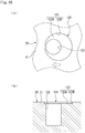
FIG. 10 illustrates a multi-stepped recess portion of sliding components according to a second embodiment of the present invention,FIG. 10A is an enlarged plan view illustrating a dynamic pressure recess portion and a static pressure recess portion constituting the multi-stepped recess portion in the sliding surface of the mating ring, andFIG. 10B is an enlarged cross-sectional view of the same. -
FIG. 11 is a cross-sectional view at a time of non-rotation in which the seal ring and the mating ring of sliding components according to a third embodiment of the present invention are radially cut. -
FIG. 12 is a cross-sectional view at a time of non-rotation in which the seal ring and the mating ring of sliding components according to a fourth embodiment of the present invention are radially cut. - Modes for implementing sliding components according to the present invention will be described below based on embodiments.
- Sliding components according to a first embodiment of the present invention will be described with reference to
FIGS. 1 to 9 . It should be noted that a mechanical seal as an example of sliding components will be described as the present embodiment. In addition, the outer peripheral side of the sliding component constituting the mechanical seal is the sealed fluid side and the inner peripheral side of the sliding component is the atmosphere side. - The mechanical seal for general industrial machinery illustrated in
FIG. 1 is an inside mechanical seal that seals a sealed fluid to leak from the outer peripheral side to the inner peripheral side of a sliding surface. The mechanical seal for general industrial machinery illustrated inFIG. 1 mainly includes anannular mating ring 20 and anannular seal ring 10. Themating ring 20 is provided on a rotary shaft 1 side in a state of being rotatable integrally with the rotary shaft 1 via asleeve 2. Theseal ring 10 is provided on a seal cover 5 fixed to a housing 4 of an attached device in a non-rotation state and in a state of being axially movable. By abellows 7 biasing theseal ring 10 in the axial direction, a slidingsurface 11 of theseal ring 10 and a slidingsurface 21 of themating ring 20 mirror-finished by wrapping or the like slide closely together. It should be noted that the sealed fluid in this implementation is a high-pressure liquid of 0.1 MPa or more. - Although the
seal ring 10 and themating ring 20 are typically formed of SiC (grouped into hard material) or a combination of SiC (grouped into hard material) and carbon (grouped into soft material), the present invention is not limited thereto and a sliding material is applicable insofar as the sliding material is used as a sliding material for a mechanical seal. It should be noted that a material including two or more phases different in component and composition and including a sintered body using boron, aluminum, carbon, or the like as a sintering aid can be used as the SiC. It should be noted that examples of the material include SiC in which graphite particles are dispersed, reaction sintered SiC containing SiC and Si, SiC-TiC, and SiC-TiN. It should be noted that resin-molded carbon, sintered carbon, and the like can be used as the carbon, examples of which include carbonaceous and graphitic mixed carbon. In addition, other than the sliding material described above, a metal material, a resin material, a surface modifying material (or coating material), a composite material, and the like are also applicable. - As illustrated in
FIG. 2 , theseal ring 10 has the slidingsurface 11, which is annular in a front view seen from the axial direction, at one end in the axial direction. The slidingsurface 11 is formed as a flat surface. - As illustrated in
FIG. 3 , themating ring 20 has the annular slidingsurface 21 facing the slidingsurface 11 of theseal ring 10 in the axial direction. The slidingsurface 21, which is a flat surface, has, in the circumferential direction, a plurality ofmulti-stepped recess portions 24 in which at least two steps are formed and dimples 25 (also referred to as non-multi-stepped recess portions or dimples) in which only one step or no step is formed. Themulti-stepped recess portion 24, which is disposed on the outer diameter side (i.e., sealed fluid side in the embodiment) of the slidingsurface 21, includes a dimple 22 (also referred to as a static pressure recess portion) and a counterbore 23 (also referred to as a dynamic pressure recess portion) formed around thedimple 22. It should be noted that the slidingsurface 21 can be said to be a land portion with respect to themulti-stepped recess portion 24 and thedimple 25 and thecounterbore 23 is surrounded by the slidingsurface 21 without interruption over the entire circumference. - In addition, a radial length w21 of the sliding
surface 21 of themating ring 20 is formed longer than a radial length w11 of the slidingsurface 11 of the seal ring 10 (i.e., w11 < w21, seeFIG. 5 ). - The
dimple 22 of themulti-stepped recess portion 24 is formed in a circular shape in the front view seen from the axial direction (seeFIGS. 3 and4A ) and is formed in a columnar shape having a substantially rectangular cross section in the radial direction (seeFIGS. 4B and5 ). Thedimples 22 of themulti-stepped recess portions 24 are disposed in a staggered manner, six by six along with thedimples 25, in the radial direction in the entire slidingsurface 21. It should be noted that the entire slidingsurface 21 indicates a region that substantially slides on the slidingsurface 11. Further, it should be noted that thedimple 25 and thedimple 22 of themulti-stepped recess portion 24 of the present embodiment are formed by laser machining, the present invention is not limited thereto, and thedimple 25 and thedimple 22 of themulti-stepped recess portion 24 of the present embodiment may be formed by another method. - In addition, a depth dimension h22 of the
dimple 22 of themulti-stepped recess portion 24 is formed larger than an opening maximum diameter dimension r22 of thedimple 22 in the front view (i.e. r22 < h22, seeFIG. 4 ). As a result, the function of thedimple 22 of supplying the sealed fluid to thecounterbore 23 formed around thedimple 22 is enhanced and the function of thedimple 22 of internally holding the sealed fluid is enhanced. It should be noted that the depth dimension h22 of thedimple 22 may be formed smaller than or substantially equal to the opening maximum diameter dimension r22 of thedimple 22 in the front view. In addition, it is preferable that the axial depth dimension h22 of thedimple 22 is 10 µm or more, at which no wedge action acts sufficiently. - The
counterbore 23 is defined by abottom surface 23A formed as a flat surface parallel to the slidingsurface 21 on the outer diameter side of thedimple 22 and an innerperipheral wall 23B formed as a wall surface orthogonal to thebottom surface 23A. Thecounterbore 23 is formed in a circular shape in the front view seen from the axial direction (seeFIGS. 3 and4A ) and as a concentric shallow groove surrounding the periphery of thedimple 22. As a result, the machining of thecounterbore 23 and thedimple 22 in the slidingsurface 21 can be facilitated and use for the bidirectional relative rotation of theseal ring 10 and themating ring 20 is possible. In addition, in themulti-stepped recess portion 24, thecounterbore 23 and thedimple 22 are formed in a circular shape in the front view, and thus the pressure that is generated in thecounterbore 23 can be raised smoothly. Further, the innerperipheral wall 23B of thecounterbore 23 is formed so as to be orthogonal in an edge shape to the slidingsurface 21, and thus a large positive pressure can be generated. It should be noted that thecounterbore 23 of themulti-stepped recess portion 24 of the present embodiment is formed by laser machining, the present invention is not limited thereto, and thecounterbore 23 of themulti-stepped recess portion 24 of the present embodiment may be formed by another method. - In addition, a depth dimension h23 of the
counterbore 23 is formed smaller than an opening maximum diameter dimension r23 of thecounterbore 23 in the front view (i.e., h23 < r23, seeFIG. 4 ). As a result, thecounterbore 23 is capable of generating sufficient dynamic pressure between the slidingsurfaces counterbore 23 is formed to be less than 5 µm, the axial depth of thecounterbore 23 is preferably formed to be 1 µm or more, and thecounterbore 23 is formed only in the dimple 22 (of the multi-stepped recess portion 24) disposed in the region of 1/2 or less, preferably 1/4 or less, in the radial direction on the outer diameter side of the sliding surface 21 (seeFIG. 3 ). As a result, the total force (i.e., buoyancy) of the dynamic pressures respectively generated in thecounterbores 23 does not excessively increase. It should be noted that it is preferable that thecounterbore 23 is not disposed on the inner diameter side of the slidingsurface 11. In this manner, the outer diameter side of the slidingsurface 21 is unlikely to come into direct contact with the facing slidingsurface 11 during the relative rotation of theseal ring 10 and themating ring 20 and poor lubrication on the outer diameter side with a high rotation speed can be prevented. - As illustrated in
FIG. 4A , in themulti-stepped recess portion 24, the opening maximum diameter dimension r23 of thecounterbore 23 is formed larger than the opening maximum diameter dimension r22 of the dimple 22 (i.e., r22 < r23). In addition, as illustrated inFIG. 4B , the depth dimension h22 of thedimple 22 is formed larger than the depth dimension h23 of the counterbore 23 (i.e., h23 < h22). In this manner, themulti-stepped recess portion 24 is formed in a stepwise shape in a cross-sectional view by thedimple 22 and thecounterbore 23. Further, the circumferential length (L1) of thedimple 22 is formed longer than the circumferential length (2 × L2) of the counterbore 23 (or thebottom surface 23A) (i.e., 2 × L2 < L1). As a result, the region of static pressure generation exceeds the region of dynamic pressure generation in themulti-stepped recess portion 24, and thus the function of fluid holding by thedimple 22 can be enhanced. - Next, dynamic pressure generation between the sliding
surfaces FIG. 6 , when theseal ring 10 and themating ring 20 rotate relative to each other (in the rotation direction that is indicated by the white arrow inFIG. 6 , which is from the upper side of the page to the lower side of the page), the counter-rotation direction side of thecounterbore 23 in the multi-stepped recess portion 24 (i.e., lower side of the page ofFIG. 6 : the opposite rotation direction side on the basis of the rotation direction of the counterpart-side seal ring 10) has a negative pressure whereas a positive pressure is generated on the rotation direction side (i.e., upper side of the page ofFIG. 6 ). Then, the positive pressure is increased by the wedge action of the innerperipheral wall 23B on the rotation direction side of thecounterbore 23, the positive pressure acts as a whole, and large buoyancy is obtained. In addition, thecounterbore 23 is supplied with the sealed fluid from thedimple 22, which is deeper than thecounterbore 23, and thus dynamic pressure can be reliably generated without poor lubrication. At this time, thecounterbore 23 mainly fulfills a function to generate dynamic pressure between the slidingsurfaces surfaces dimple 22 mainly fulfills a function to supply thecounterbore 23 with the sealed fluid held in thedimple 22. In addition, the non-multi-steppeddimple 25, where thecounterbore 23 is not formed, also fulfills a function to internally hold the sealed fluid on the inner diameter side of the slidingsurface 21, and thus poor lubrication is unlikely to occur on the slidingsurfaces surface 11 overlaps thecounterbore 23 of themulti-stepped recess portion 24, which is formed on the outer diameter side of the slidingsurface 21, in the radial direction as illustrated inFIG. 5 , thecounterbore 23 is not open to the outer diameter side (i.e., sealed fluid side in the embodiment) between the slidingsurfaces counterbore 23 is enhanced. It should be noted that the slidingsurfaces FIG. 6 , due to surface roughness, undulation, and deformation attributable to dynamic pressure. - In this manner, the
multi-stepped recess portion 24 generates dynamic pressure, by thecounterbore 23 and thedimple 22 cooperating, to the extent that theseal ring 10 and themating ring 20 do not completely float relative to each other. As a result, mixed lubrication is performed on the slidingsurfaces surfaces surfaces surfaces - It should be noted that the inner
peripheral wall 23B of thecounterbore 23 may not be orthogonal to thebottom surface 23A and may, for example, intersect in an inclined state in a variation of thecounterbore 23 of themulti-stepped recess portion 24 in the first embodiment. In addition, thebottom surface 23A may not be parallel to the slidingsurface 21 and may be, for example, an inclined surface. Further, thebottom surface 23A may not be a flat surface and may be, for example, a curved surface. - In addition, in a variation A of the
dimple 22 of themulti-stepped recess portion 24 in the first embodiment, the cross-sectional shape of thedimple 22 may be formed in the conical shape that is illustrated inFIG. 7A or the semi-spheroidal shape that is illustrated inFIG. 7B . - In addition, in a variation B of the
counterbore 23 of themulti-stepped recess portion 24 in the first embodiment, thecounterbore 23 may be formed as a two-stage counterbore having different depth dimensions as illustrated inFIG. 8 . In this manner, it is possible to give a steep peak to the positive pressure that is generated in the counterbore, and thus the dynamic pressure generation efficiency can be enhanced. It should be noted that the counterbore is not limited to having a two-stage cross section and the counterbore may be formed in a plurality of stages having different depths in cross section. - Further, in a variation C of the
multi-stepped recess portion 24 of the first embodiment, the shape in a plan view is different as illustrated inFIGS. 9A to 9D . It should be noted that the right and left direction inFIG. 9 is a direction along the circumferential direction of the slidingsurface 21 and the up and down direction inFIG. 9 is the radial direction of the slidingsurface 21. - As illustrated in
FIG. 9A , amulti-stepped recess portion 24a is formed in a stadium shape as a whole in the front view with adimple 22a, which is rectangular in the front view, sandwiched between twocounterbores 23a, which are semicircular in the front view. - As illustrated in
FIG. 9B , amulti-stepped recess portion 24b is formed in a square shape as a whole in the front view with asmall dimple 22b, which is square in the front view, disposed in the middle of acounterbore 23b, which is square in the front view. - As illustrated in
FIG. 9C , amulti-stepped recess portion 24c as a whole is formed in a belt shape in the front view with twocounterbores 23c substantially rectangular in the front view sandwiching adimple 22c substantially rectangular in the front view andcircumferential surfaces 24x and 24y parallel to an outerperipheral surface 20x of themating ring 20. - As illustrated in
FIG. 9D , amulti-stepped recess portion 24d is formed in a circular shape as a whole in the front view with twosmall dimples counterbore 23d, which is circular in the front view. - It should be noted that the
multi-stepped recess portion 24 can be configured by mutual combinations of variations A to C as a matter of course. - Next, sliding components according to a second embodiment of the present invention will be described with reference to
FIG. 10 . It should be noted that the same components as those described in the above embodiment are denoted by the same reference numerals without redundant description. - The sliding components in the second embodiment will be described. A dimple 122 (also referred to as a static pressure recess portion) of a
multi-stepped recess portion 124 is formed in a circular shape in a front view seen from the axial direction as illustrated inFIG. 10A and in a columnar shape having a substantially rectangular cross section in the radial direction as illustrated inFIG. 10B . - A counterbore 123 (also referred to as a dynamic pressure recess portion) is defined by a
bottom surface 123A formed as a flat surface parallel to the slidingsurface 21 on the outer diameter side of thedimple 122 and an innerperipheral wall 123B formed as a wall surface orthogonal to thebottom surface 123A. Thecounterbore 123 is formed in a circular shape in the front view seen from the axial direction (seeFIG. 10A ) and as a shallow groove eccentric to the rotation direction side of the multi-stepped recess portion 124 (left side of the page ofFIG. 10 ). - According to such a configuration, it is possible to generate a wide positive pressure region on the rotation direction side of the counterbore 123 (i.e., right side of the page of
FIG. 10 ) with respect to the unidirectional relative rotation of theseal ring 10 and the mating ring 20 (in the rotation direction that is indicated by the white arrow inFIG. 10A , which is from the right side of the page to the left side of the page) and a narrow negative pressure region on the counter-rotation direction side (i.e., left side of the page ofFIG. 10 ). Accordingly, the efficiency of dynamic pressure generation can be enhanced. - Next, sliding components according to a third embodiment of the present invention will be described with reference to
FIG. 11 . It should be noted that the same components as those described in the above embodiments are denoted by the same reference numerals without redundant description. - The sliding components in the third embodiment will be described. As illustrated in
FIG. 11 , the outer diameter side (i.e., sealed fluid side in the embodiment) of thecounterbore 23 of themulti-stepped recess portion 24 formed on the outer diameter side of the slidingsurface 21 is slightly open between the slidingsurfaces surfaces 11 and 21 (i.e., w11 < w21). - According to such a configuration, the
multi-stepped recess portion 24 is capable of contributing to the dynamic pressure generation between the slidingsurfaces counterbore 23. - Next, sliding components according to a fourth embodiment of the present invention will be described with reference to
FIG. 12 . It should be noted that the same components as those described in the above embodiments are denoted by the same reference numerals without redundant description. - The sliding components in the fourth embodiment will be described. As illustrated in
FIG. 12 , an axially recessedstep portion 26 is formed on the outer diameter side of themating ring 20 and thecounterbore 23 of themulti-stepped recess portion 24 formed on the outer diameter side of the slidingsurface 21 is slightly open on the outer diameter side (i.e., sealed fluid side in the embodiment) between the slidingsurfaces - Although embodiments of the present invention have been described above with reference to the drawings, specific configurations are not limited to the embodiments. Changes and additions without departing from the spirit of the present invention are also included in the present invention.
- In addition, although a case where a sliding component constitutes a mechanical seal has been described as an example in the embodiment described above, the present invention is not construed as being limited thereto. Various changes, modifications, and improvements based on the knowledge of those skilled in the art can be made without departing from the scope of the present invention.
- For example, although a mechanical seal for general industrial machinery has been described as an example of the sliding component, another mechanical seal such as a mechanical seal for water pumps may also be used. In addition, the mechanical seal may also be an outside mechanical seal.
- In addition, although an example in which a multi-stepped recess portion and a non-multi-stepped dimple are provided only in a mating ring has been described in the embodiment described above, the multi-stepped recess portion and the non-multi-stepped dimple may be provided only in a seal ring or may be provided in both the seal ring and the mating ring.
- In addition, the present invention is not limited to the description of the embodiment in which the multi-stepped recess portion is disposed over the circumferential direction on the outer diameter side of the sliding surface and the non-multi-stepped dimple is disposed on the inner diameter side. For example, only the multi-stepped recess portion may be disposed on the outer diameter side of the sliding surface with no non-multi-stepped dimple disposed. Alternatively, the multi-stepped recess portion may be disposed on the entire surface of the sliding surface with no non-multi-stepped dimple disposed. Alternatively, the multi-stepped recess portion and the non-multi-stepped dimple may be alternately disposed in the circumferential direction on the outer diameter side of the sliding surface. It should be noted that too many multi-stepped recess portions result in an increase in generated dynamic pressure, too few multi-stepped recess portions result in more change in dynamic pressure acting over the circumferential direction of the sliding surface, and thus it is preferable to appropriately set the number of the multi-stepped recess portions in accordance with the environment of use and the like.
- In addition, although a mechanical seal has been described as an example of a sliding component, a nonmechanical seal sliding component such as a slide bearing may also be used.
-
- 1
- Rotary shaft
- 2
- Sleeve
- 4
- Housing
- 5
- Seal cover
- 7
- Bellows
- 10
- Seal ring (sliding components)
- 11
- Sliding surface
- 20
- Mating ring (sliding components)
- 21
- Sliding surface
- 22
- Dimple (static pressure recess portion)
- 23
- Counterbore (dynamic pressure recess portion)
- 23A
- Bottom surface
- 23B
- Inner peripheral wall
- 24
- Multi-stepped recess portion
- 25
- Dimple (non-multi-stepped recess portion)
- 122
- Dimple (static pressure recess portion)
- 123
- Counterbore (dynamic pressure recess portion)
- 123A
- Bottom surface
- 123B
- Inner peripheral wall
- 124
- Multi-stepped recess portion
Claims (10)
- Sliding components having sliding surfaces rotated relative to each other with an annular mating ring and an annular seal ring facing each other and, as a result, sealing a sealed fluid present on one radial side of each of the sliding surfaces rotating and sliding relative to each other, wherein
the sliding surface of at least one of the mating ring and the seal ring has therein a plurality of multi-stepped recess portions arranged in a circumferential direction and relative rotation and sliding of the mating ring and the seal ring causes the multi-stepped recess portions to generate a dynamic pressure, and wherein
each of the multi-stepped recess portions is formed in a stepwise shape in a cross-sectional view by a dynamic pressure recess portion and a static pressure recess portion with the dynamic pressure recess portion surrounding the static pressure recess portion deeper than the dynamic pressure recess portion. - The sliding components according to claim 1, wherein the dynamic pressure recess portion and the static pressure recess portion are circular in a plan view.
- The sliding components according to claim 1 or 2, wherein the dynamic pressure recess portion is provided concentrically with the static pressure recess portion.
- The sliding components according to claim 1 or 2, wherein the dynamic pressure recess portion is provided eccentrically in a rotation direction with respect to the static pressure recess portion.
- The sliding components according to any one of claims 1 to 4, wherein a circumferential length of the static pressure recess portion is longer than a circumferential length of the dynamic pressure recess portion.
- The sliding components according to any one of claims 1 to 5, wherein the dynamic pressure recess portion includes a plurality of steps having different depths in cross section.
- The sliding components according to any one of claims 1 to 6, wherein the plurality of multi-stepped recess portions is disposed only on the sealed fluid side of the sliding surface of the mating ring or the seal ring.
- The sliding components according to claim 7, wherein a non-multi-stepped recess portion different in a cross-sectional view from each of the multi-stepped recess portions is disposed in the sliding surface of at least one of the mating ring and the seal ring.
- The sliding components according to any one of claims 1 to 8, wherein the dynamic pressure recess portion has a depth dimension smaller than an opening maximum diameter dimension thereof in a plan view and the static pressure recess portion has a depth dimension of 10 µm or more.
- The sliding components according to any one of claims 1 to 9, wherein the sealed fluid is a high-pressure liquid of 0.1 MPa or more.
Applications Claiming Priority (2)
| Application Number | Priority Date | Filing Date | Title |
|---|---|---|---|
| JP2018016629 | 2018-02-01 | ||
| PCT/JP2019/003381 WO2019151396A1 (en) | 2018-02-01 | 2019-01-31 | Sliding parts |
Publications (4)
| Publication Number | Publication Date |
|---|---|
| EP3748205A1 true EP3748205A1 (en) | 2020-12-09 |
| EP3748205A4 EP3748205A4 (en) | 2021-11-10 |
| EP3748205B1 EP3748205B1 (en) | 2024-12-18 |
| EP3748205C0 EP3748205C0 (en) | 2024-12-18 |
Family
ID=67479687
Family Applications (1)
| Application Number | Title | Priority Date | Filing Date |
|---|---|---|---|
| EP19748058.5A Active EP3748205B1 (en) | 2018-02-01 | 2019-01-31 | Sliding parts |
Country Status (6)
| Country | Link |
|---|---|
| US (2) | US11320052B2 (en) |
| EP (1) | EP3748205B1 (en) |
| JP (1) | JP7139077B2 (en) |
| KR (1) | KR102420417B1 (en) |
| CN (1) | CN111656065B (en) |
| WO (1) | WO2019151396A1 (en) |
Families Citing this family (23)
| Publication number | Priority date | Publication date | Assignee | Title |
|---|---|---|---|---|
| DK2565279T3 (en) | 2007-12-05 | 2015-02-16 | Complete Genomics Inc | Efficient base determination in sequencing reactions |
| CN102459592B (en) | 2009-06-15 | 2017-04-05 | 考利达基因组股份有限公司 | Methods and compositions for long read sequencing |
| US10837879B2 (en) | 2011-11-02 | 2020-11-17 | Complete Genomics, Inc. | Treatment for stabilizing nucleic acid arrays |
| USRE50849E1 (en) | 2016-11-16 | 2026-03-31 | Eagle Industry Co., Ltd. | Sliding component |
| EP3739242A4 (en) | 2018-01-12 | 2021-10-13 | Eagle Industry Co., Ltd. | SLIDING ELEMENT |
| JP7139077B2 (en) | 2018-02-01 | 2022-09-20 | イーグル工業株式会社 | sliding parts |
| KR102647265B1 (en) | 2019-02-04 | 2024-03-14 | 이구루코교 가부시기가이샤 | sliding parts |
| CN113348308B (en) | 2019-02-04 | 2023-05-05 | 伊格尔工业股份有限公司 | Sliding member |
| EP3922874A4 (en) | 2019-02-04 | 2022-11-09 | Eagle Industry Co., Ltd. | SLIDING ELEMENT |
| WO2020162351A1 (en) | 2019-02-04 | 2020-08-13 | イーグル工業株式会社 | Sliding component |
| EP4253779B1 (en) | 2019-02-04 | 2024-12-18 | Eagle Industry Co., Ltd. | Sliding component and method for manufacturing sliding component |
| WO2020166589A1 (en) * | 2019-02-14 | 2020-08-20 | イーグル工業株式会社 | Sliding components |
| JP7419346B2 (en) | 2019-03-22 | 2024-01-22 | イーグル工業株式会社 | sliding parts |
| CN115298462B (en) | 2020-03-31 | 2025-04-11 | 伊格尔工业股份有限公司 | Sliding member |
| KR102798715B1 (en) | 2020-05-11 | 2025-04-23 | 이구루코교 가부시기가이샤 | Sliding parts |
| EP4177485A4 (en) | 2020-07-06 | 2024-07-24 | Eagle Industry Co., Ltd. | SLIDING COMPONENT |
| KR20230022986A (en) * | 2020-07-06 | 2023-02-16 | 이구루코교 가부시기가이샤 | sliding parts |
| WO2022009771A1 (en) | 2020-07-06 | 2022-01-13 | イーグル工業株式会社 | Sliding component |
| KR20230027187A (en) | 2020-07-06 | 2023-02-27 | 이구루코교 가부시기가이샤 | sliding parts |
| WO2022009766A1 (en) * | 2020-07-06 | 2022-01-13 | イーグル工業株式会社 | Sliding component |
| WO2022009770A1 (en) | 2020-07-06 | 2022-01-13 | イーグル工業株式会社 | Sliding component |
| EP4394213A4 (en) | 2021-08-25 | 2025-08-27 | Eagle Ind Co Ltd | PAIR OF SLIDING COMPONENTS |
| CN119301388A (en) * | 2022-06-07 | 2025-01-10 | 伊格尔工业股份有限公司 | Sliding parts |
Family Cites Families (162)
| Publication number | Priority date | Publication date | Assignee | Title |
|---|---|---|---|---|
| US3383116A (en) * | 1964-09-30 | 1968-05-14 | J C Carter Company | Face seal |
| FR1505487A (en) | 1966-10-28 | 1967-12-15 | Guinard Pompes | Improvement in leak-controlled rotary joints |
| US3704019A (en) | 1970-06-19 | 1972-11-28 | Gen Electric | Spiral groove face seals |
| US3675935A (en) | 1970-07-13 | 1972-07-11 | Nasa | Spiral groove seal |
| US3782737A (en) | 1970-07-13 | 1974-01-01 | Nasa | Spiral groove seal |
| US4056478A (en) | 1973-10-04 | 1977-11-01 | Sargent Industries, Inc. | Bearing material employing frangible microcapsules containing lubricant |
| JPS5134974A (en) | 1974-09-19 | 1976-03-25 | Kinugawa Rubber Ind | Dainamitsukushiiru no seiho |
| DE2504204C3 (en) | 1975-02-01 | 1981-11-12 | Skf Kugellagerfabriken Gmbh, 8720 Schweinfurt | Self-pressure generating axial slide bearing |
| FR2342440A1 (en) | 1976-02-27 | 1977-09-23 | Ca Atomic Energy Ltd | Face seal for rotating shaft - has collar with chain of blind holes connected by grooves to increase resistance to flow |
| DE2610045C2 (en) * | 1976-03-11 | 1982-06-16 | M.A.N. Maschinenfabrik Augsburg-Nürnberg AG, 4200 Oberhausen | Gas-locked shaft seal |
| DE2622772C3 (en) | 1976-05-21 | 1980-05-08 | Hoesch Werke Ag, 4600 Dortmund | Device for transporting and changing rolls on roll processing machines |
| JPS57163770A (en) | 1981-04-01 | 1982-10-08 | Eagle Ind Co Ltd | Mechanical seal |
| DE3223703C2 (en) | 1982-06-25 | 1984-05-30 | M.A.N. Maschinenfabrik Augsburg-Nürnberg AG, 4200 Oberhausen | Gas-locked shaft seal with radial sealing gap |
| JPS59195254A (en) | 1983-04-20 | 1984-11-06 | Fujitsu Ltd | Printing device |
| JPS59195253A (en) | 1983-04-20 | 1984-11-06 | Canon Inc | Electrophotographic apparatus |
| CH677266A5 (en) | 1986-10-28 | 1991-04-30 | Pacific Wietz Gmbh & Co Kg | |
| US4889348A (en) | 1987-06-10 | 1989-12-26 | John Crane-Houdaille, Inc. | Spiral groove seal system for high vapor-pressure liquids |
| DE3839106A1 (en) | 1988-11-18 | 1990-05-23 | Burgmann Dichtungswerk Feodor | MECHANICAL SEAL |
| JPH02136863A (en) | 1988-11-18 | 1990-05-25 | Toshiba Corp | Developer for image forming device |
| JPH06105105B2 (en) | 1989-03-03 | 1994-12-21 | 日本ピラー工業株式会社 | Non-contact end face mechanical seal |
| JPH0660690B2 (en) | 1990-06-18 | 1994-08-10 | 日本ピラー工業株式会社 | Dynamic pressure non-contact mechanical seal |
| JPH0756345B2 (en) | 1990-07-09 | 1995-06-14 | 株式会社荏原製作所 | Non-contact end face seal |
| US5071141A (en) | 1990-07-17 | 1991-12-10 | John Crane Inc. | Spiral groove seal arrangement for high vapor-pressure liquids |
| US5224714A (en) | 1990-07-18 | 1993-07-06 | Ebara Corporation | Noncontacting face seal |
| JPH07117167B2 (en) | 1991-05-09 | 1995-12-18 | 日本ピラー工業株式会社 | Non-contact mechanical seal device |
| JP2516301B2 (en) | 1991-06-13 | 1996-07-24 | インターナショナル・ビジネス・マシーンズ・コーポレイション | Tape drive |
| US5174584A (en) * | 1991-07-15 | 1992-12-29 | General Electric Company | Fluid bearing face seal for gas turbine engines |
| JPH0560247A (en) | 1991-08-26 | 1993-03-09 | Nippon Pillar Packing Co Ltd | Noncontact type mechanical seal |
| JPH0680623B2 (en) | 1991-09-25 | 1994-10-12 | 北海道電力株式会社 | Power transformers for power supply and demand |
| US5447316A (en) * | 1992-02-06 | 1995-09-05 | Eagle Industry Co., Ltd. | Gas seal |
| JPH05296248A (en) | 1992-04-21 | 1993-11-09 | Sumitomo Electric Ind Ltd | Sliding member |
| JP3517888B2 (en) | 1992-09-18 | 2004-04-12 | ブラザー工業株式会社 | Color electrophotographic image forming apparatus |
| JPH0769020B2 (en) | 1992-10-07 | 1995-07-26 | 日本ピラー工業株式会社 | mechanical seal |
| JPH0769021B2 (en) | 1992-12-11 | 1995-07-26 | 日本ピラー工業株式会社 | Non-contact type shaft seal device |
| US5441283A (en) | 1993-08-03 | 1995-08-15 | John Crane Inc. | Non-contacting mechanical face seal |
| AU685502B2 (en) | 1993-09-01 | 1998-01-22 | Durametallic Corporation | Face seal with angled and annular grooves |
| US5558341A (en) | 1995-01-11 | 1996-09-24 | Stein Seal Company | Seal for sealing an incompressible fluid between a relatively stationary seal and a movable member |
| US5769604A (en) * | 1995-05-04 | 1998-06-23 | Eg&G Sealol, Inc. | Face seal device having high angular compliance |
| JP2903458B2 (en) | 1995-09-29 | 1999-06-07 | 日本ピラー工業株式会社 | Hot water shaft sealing device for large water circulation pump |
| JPH09292034A (en) | 1996-04-25 | 1997-11-11 | Mitsubishi Heavy Ind Ltd | Mechanical seal |
| US5833518A (en) | 1996-08-02 | 1998-11-10 | Flowserve Management Company | Method for forming a wavy face ring |
| US5834094A (en) * | 1996-09-30 | 1998-11-10 | Surface Technologies Ltd. | Bearing having micropores and design method thereof |
| JPH10281299A (en) | 1997-04-11 | 1998-10-23 | Mitsubishi Heavy Ind Ltd | Mechanical seal device |
| JPH10292867A (en) | 1997-04-16 | 1998-11-04 | Mitsubishi Heavy Ind Ltd | Gas seal device |
| US6152452A (en) | 1997-10-17 | 2000-11-28 | Wang; Yuming | Face seal with spiral grooves |
| BR9714210A (en) * | 1997-11-21 | 2000-03-28 | Nippon Pillar Packing | Static pressure non-contact gas sealing |
| CN1133834C (en) | 1997-11-21 | 2004-01-07 | 日本皮拉工业株式会社 | Static pressure non-contact air seal |
| JPH11287329A (en) | 1998-04-03 | 1999-10-19 | Eagle Ind Co Ltd | Sliding material |
| JP3066367B1 (en) | 1999-03-04 | 2000-07-17 | 日本ピラー工業株式会社 | Shaft sealing device |
| US6213473B1 (en) | 1999-03-06 | 2001-04-10 | Utex Industries, Inc. | Double gas seal with coplanar pad faces |
| JP4232278B2 (en) | 1999-06-25 | 2009-03-04 | パナソニック株式会社 | Hydrodynamic bearing and spindle motor equipped with the same |
| JP3066367U (en) | 1999-08-05 | 2000-02-18 | 第一精工株式会社 | Recreational fishing containers and accessories |
| US7044470B2 (en) * | 2000-07-12 | 2006-05-16 | Perkinelmer, Inc. | Rotary face seal assembly |
| US6446976B1 (en) | 2000-09-06 | 2002-09-10 | Flowserve Management Company | Hydrodynamic face seal with grooved sealing dam for zero-leakage |
| CN2460801Y (en) | 2001-01-18 | 2001-11-21 | 王玉明 | Sealing device for spiral flute end capable of bidirectional rotation |
| US6655693B2 (en) | 2001-04-26 | 2003-12-02 | John Crane Inc. | Non-contacting gas compressor seal |
| US6692006B2 (en) | 2001-10-15 | 2004-02-17 | Stein Seal Company | High-pressure film-riding seals for rotating shafts |
| JP4054608B2 (en) | 2002-05-23 | 2008-02-27 | イーグル工業株式会社 | Plate brush seal |
| CN100427816C (en) | 2002-09-20 | 2008-10-22 | 徐万福 | Helical flute and face mechanial seal composed of angular microflute group |
| JP4316956B2 (en) | 2002-10-23 | 2009-08-19 | イーグル工業株式会社 | Sliding parts |
| JP4719414B2 (en) | 2003-12-22 | 2011-07-06 | イーグル工業株式会社 | Sliding parts |
| JP4119398B2 (en) | 2004-04-30 | 2008-07-16 | 日本ピラー工業株式会社 | Non-contact mechanical seal |
| GB2413603A (en) * | 2004-04-30 | 2005-11-02 | Corac Group Plc | A dry gas seal assembly |
| US7377518B2 (en) | 2004-05-28 | 2008-05-27 | John Crane Inc. | Mechanical seal ring assembly with hydrodynamic pumping mechanism |
| JP4262656B2 (en) * | 2004-09-10 | 2009-05-13 | 日本ピラー工業株式会社 | Non-contact type sealing device |
| JP2006090524A (en) | 2004-09-27 | 2006-04-06 | Nissei Co Ltd | Dynamic pressure fluid bearing |
| JP4820471B2 (en) * | 2004-11-09 | 2011-11-24 | イーグル工業株式会社 | Mechanical seal device |
| JP2006183702A (en) | 2004-12-27 | 2006-07-13 | Hitachi Industrial Equipment Systems Co Ltd | Thrust bearing |
| JP2007162045A (en) | 2005-12-12 | 2007-06-28 | Japan Science & Technology Agency | Sliding material and manufacturing method thereof |
| US20070228664A1 (en) | 2006-03-31 | 2007-10-04 | Krishnamurthy Anand | Mechanical seals and methods of making |
| US7793940B2 (en) | 2006-05-16 | 2010-09-14 | Skf Usa Inc. | Mechanical end face seal with ultrahard face material |
| EP2047149B1 (en) | 2006-05-26 | 2015-08-12 | Sulzer Metco (US) Inc. | Mechanical seals and method of manufacture |
| US20080284105A1 (en) | 2006-06-21 | 2008-11-20 | Thurai Manik Vasagar | Low and reverse pressure application hydrodynamic pressurizing seals |
| WO2008013147A1 (en) | 2006-07-25 | 2008-01-31 | Eagle Industry Co., Ltd. | Mechanical seal device |
| JP4673807B2 (en) * | 2006-08-02 | 2011-04-20 | 日本ピラー工業株式会社 | Hydrostatic non-contact gas seal |
| US8162322B2 (en) | 2006-10-25 | 2012-04-24 | Rexnord Industries, Llc | Hydrodynamic seal with circumferentially varying lift force |
| EP2213915B1 (en) | 2007-11-20 | 2018-05-23 | Eagle Industry Co., Ltd. | Mechanical seal and tandem seal |
| US20090326087A1 (en) | 2008-06-27 | 2009-12-31 | Xerox Corporation | Method for treating microcapsules for use in imaging member |
| DE102008038396A1 (en) | 2008-08-19 | 2010-02-25 | Surcoatec International Ag | Sliding ring for a mechanical seal |
| US8100405B2 (en) | 2009-01-06 | 2012-01-24 | General Electric Company | System and method for providing compliant rotating seals |
| JP5757087B2 (en) | 2009-02-10 | 2015-07-29 | Nok株式会社 | Sliding member and manufacturing method thereof |
| EP2375112B1 (en) | 2009-05-25 | 2018-07-18 | Eagle Industry Co., Ltd. | Sealing device |
| CN101793324B (en) | 2009-08-06 | 2011-12-28 | 浙江工业大学 | Hydrodynamic mechanical seal structure for three-dimensional fish scale-like texture bottom surface type groove |
| CN201496542U (en) * | 2009-08-06 | 2010-06-02 | 浙江工业大学 | Three-dimensional fish scale-constructed underside-type trough fluid dynamic-pressure type liquid mechanical sealing structure |
| CN101644333B (en) | 2009-08-20 | 2011-08-31 | 浙江工业大学 | Gas end surface sealing structure with three-dimensional feather-like textured bottom shaped grooves |
| US7931277B2 (en) | 2009-08-27 | 2011-04-26 | Stein Seal Company | Hydrodynamic circumferential seal system for large translations |
| JP2011074931A (en) | 2009-09-29 | 2011-04-14 | Ihi Corp | Sealing device for combustible gas compressor |
| CN102483162A (en) | 2010-02-26 | 2012-05-30 | Nok株式会社 | sealing ring |
| JP5518527B2 (en) * | 2010-03-04 | 2014-06-11 | イーグル工業株式会社 | Sliding parts |
| EP2549155B1 (en) | 2010-03-15 | 2016-08-10 | Eagle Industry Co., Ltd. | Sliding member |
| JP5122607B2 (en) | 2010-06-17 | 2013-01-16 | キヤノンマシナリー株式会社 | Flat sliding mechanism |
| DE202010011173U1 (en) | 2010-08-09 | 2011-12-22 | Eagleburgmann Germany Gmbh & Co. Kg | Sliding ring with improved inlet properties |
| JP2012062534A (en) | 2010-09-16 | 2012-03-29 | Jtekt Corp | Sliding member |
| CN103097782B (en) | 2010-10-06 | 2016-01-20 | 伊格尔工业股份有限公司 | Slide member |
| JP2012122135A (en) | 2010-11-18 | 2012-06-28 | Furukawa Electric Co Ltd:The | Plating assistant, plating liquid, and plating material |
| US9447884B2 (en) | 2011-09-03 | 2016-09-20 | Eagle Industry Co., Ltd. | Sliding parts |
| JP5871289B2 (en) | 2011-09-03 | 2016-03-01 | イーグル工業株式会社 | Sliding parts |
| WO2013035502A1 (en) | 2011-09-10 | 2013-03-14 | イーグル工業株式会社 | Sliding component |
| CN103732958B (en) | 2011-09-10 | 2016-09-21 | 伊格尔工业股份有限公司 | Slide unit |
| DE102011116162A1 (en) | 2011-10-14 | 2013-04-18 | Eagleburgmann Germany Gmbh & Co. Kg | Sliding ring of a mechanical seal assembly with run-time-prolonging properties and process for its preparation |
| JP5928106B2 (en) | 2012-04-02 | 2016-06-01 | オイレス工業株式会社 | Static pressure gas bearing and linear motion guide device using the static pressure gas bearing |
| CN104169622B (en) | 2012-05-21 | 2016-04-27 | 伊格尔工业股份有限公司 | Slide member |
| US9958010B2 (en) | 2012-08-04 | 2018-05-01 | Eagle Industry Co., Ltd. | Sliding component |
| EP2881632B1 (en) | 2012-08-04 | 2018-04-04 | Eagle Industry Co., Ltd. | Sliding component |
| WO2014042045A1 (en) | 2012-09-11 | 2014-03-20 | イーグル工業株式会社 | Slide part |
| US9347566B2 (en) | 2012-10-18 | 2016-05-24 | Eagle Industry Co., Ltd. | Sliding component |
| CN202867843U (en) * | 2012-11-12 | 2013-04-10 | 西华大学 | Mechanical sealing device with depthkeeping ratio step groove end face sealing ring |
| CN203098871U (en) * | 2013-01-30 | 2013-07-31 | 浙江工业大学 | Mushroom-like groove bidirectional rotating fluid moving compression mechanical sealing structure |
| JP6219367B2 (en) | 2013-03-14 | 2017-10-25 | イーグルブルグマンジャパン株式会社 | Mechanical seal device |
| AU2014239820B2 (en) | 2013-03-17 | 2016-07-21 | Eagle Industry Co., Ltd. | Sliding component |
| EP2977655B1 (en) | 2013-03-17 | 2018-07-18 | Eagle Industry Co., Ltd. | Sliding part |
| CN104919229B (en) * | 2013-04-24 | 2017-05-31 | 伊格尔工业股份有限公司 | sliding parts |
| GB2513867A (en) | 2013-05-07 | 2014-11-12 | Mahle Int Gmbh | Sliding engine component |
| CN103267132B (en) * | 2013-05-28 | 2015-08-05 | 南京林业大学 | From the mechanical seal of pumping Hydrodynamic pressure type |
| CN203641506U (en) * | 2013-08-20 | 2014-06-11 | 浙江工业大学 | Tilted gradually-changed porous end surface non-contact mechanical seal structure |
| JP6210814B2 (en) | 2013-09-26 | 2017-10-11 | ポリプラスチックス株式会社 | Sliding member |
| JP2015068330A (en) | 2013-10-01 | 2015-04-13 | 三菱重工業株式会社 | Sliding member |
| CN103557229A (en) | 2013-10-22 | 2014-02-05 | 申科滑动轴承股份有限公司 | Design method of water lubrication step tile dynamic pressure thrust bearing |
| CN103557334A (en) | 2013-11-14 | 2014-02-05 | 江苏大学 | Multiple-end face combined type mechanical seal for realizing zero leakage and non-contact |
| CN105683632B (en) * | 2013-11-22 | 2017-07-07 | 伊格尔工业股份有限公司 | Slide unit |
| US10865883B2 (en) | 2014-01-24 | 2020-12-15 | Nok Corporation | Sealing ring |
| EP3112078B1 (en) | 2014-02-24 | 2020-04-15 | Eagle Industry Co., Ltd. | Sliding member and sliding member processing method |
| US20150345642A1 (en) | 2014-05-29 | 2015-12-03 | Caterpillar Inc. | Thin film coating on mechanical face seals |
| EP3190317B1 (en) | 2014-09-04 | 2022-02-09 | Eagle Industry Co., Ltd. | Mechanical seal |
| EP3196516B1 (en) | 2014-09-20 | 2019-08-21 | Eagle Industry Co., Ltd. | Sliding component |
| JP6224568B2 (en) * | 2014-10-17 | 2017-11-01 | イーグル工業株式会社 | mechanical seal |
| US10443737B2 (en) | 2014-11-08 | 2019-10-15 | Eagle Industry Co., Ltd. | Slide component |
| EP3929455B1 (en) | 2014-12-22 | 2026-01-28 | Eagle Industry Co., Ltd. | Plain bearing and pump |
| KR101970231B1 (en) * | 2015-02-14 | 2019-04-18 | 이구루코교 가부시기가이샤 | Sliding parts |
| EP3284981B1 (en) | 2015-04-15 | 2020-11-04 | Eagle Industry Co., Ltd. | Sliding parts |
| WO2016167170A1 (en) | 2015-04-16 | 2016-10-20 | イーグル工業株式会社 | Sliding part |
| CN104948742B (en) * | 2015-05-11 | 2017-03-22 | 湖北新置密封件有限公司 | Non-contact type one-way sealing device used for high-speed rotary shafts |
| WO2016186019A1 (en) | 2015-05-19 | 2016-11-24 | イーグル工業株式会社 | Sliding component |
| JP6595589B2 (en) * | 2015-05-20 | 2019-10-23 | イーグル工業株式会社 | Sliding parts |
| JP6678170B2 (en) | 2015-05-21 | 2020-04-08 | イーグル工業株式会社 | Sliding parts |
| JP6776232B2 (en) | 2015-06-15 | 2020-10-28 | イーグル工業株式会社 | Sliding parts |
| WO2017002774A1 (en) | 2015-06-30 | 2017-01-05 | イーグル工業株式会社 | Seal device |
| US10626995B2 (en) | 2015-10-05 | 2020-04-21 | Eagle Industry Co., Ltd. | Sliding component |
| WO2017110778A1 (en) | 2015-12-25 | 2017-06-29 | 三菱マテリアル株式会社 | Sintered oil-retaining bearing and process for producing the same |
| US11162591B2 (en) | 2016-03-10 | 2021-11-02 | General Electric Company | Seal ring assembly for a dynamoelectric machine |
| US10428673B2 (en) * | 2016-05-02 | 2019-10-01 | General Electric Company | Aspirating face seal assembly and a method of operating the same |
| US11473626B2 (en) | 2016-05-16 | 2022-10-18 | Roller Bearing Company Of America, Inc. | Bearing system with self-lubrication features, seals, grooves and slots for maintenance-free operation |
| CN205877198U (en) * | 2016-06-20 | 2017-01-11 | 昆明理工大学 | Mechanical seal ring with oval groove |
| CN205877184U (en) * | 2016-06-20 | 2017-01-11 | 昆明理工大学 | Mechanical seal ring with imitative chinese sweet gum lobate shaped groove |
| CN205918902U (en) * | 2016-06-30 | 2017-02-01 | 台州市星光真空设备制造有限公司 | Mechanical seal |
| CN106439023B (en) * | 2016-07-28 | 2018-03-06 | 浙江工业大学 | A kind of cosine curve type mechanical seal end surface structure |
| AU2017318903A1 (en) * | 2016-09-01 | 2019-03-07 | Eagle Industry Co., Ltd. | Sliding component |
| KR102288158B1 (en) | 2016-11-14 | 2021-08-11 | 이구루코교 가부시기가이샤 | sliding parts |
| US11143232B2 (en) | 2016-11-16 | 2021-10-12 | Eagle Industry Co., Ltd. | Sliding component |
| KR102447226B1 (en) | 2016-12-07 | 2022-09-26 | 이구루코교 가부시기가이샤 | sliding parts |
| CN110168240B (en) | 2017-01-30 | 2021-10-15 | 伊格尔工业股份有限公司 | sliding parts |
| KR102276083B1 (en) | 2017-01-30 | 2021-07-13 | 이구루코교 가부시기가이샤 | sliding parts |
| US11248706B2 (en) * | 2017-07-07 | 2022-02-15 | Eagle Industry Co., Ltd. | Sliding member |
| JPWO2019013233A1 (en) * | 2017-07-13 | 2020-07-09 | イーグル工業株式会社 | Sliding member |
| CN107489770A (en) * | 2017-09-29 | 2017-12-19 | 重庆三峡学院 | A kind of two-way mechanical sealing ring |
| EP3693638A4 (en) | 2017-10-03 | 2021-06-23 | Eagle Industry Co., Ltd. | Sliding component |
| EP3739242A4 (en) * | 2018-01-12 | 2021-10-13 | Eagle Industry Co., Ltd. | SLIDING ELEMENT |
| JP7139077B2 (en) | 2018-02-01 | 2022-09-20 | イーグル工業株式会社 | sliding parts |
| WO2019221226A1 (en) * | 2018-05-17 | 2019-11-21 | イーグル工業株式会社 | Seal ring |
| JP7214722B2 (en) * | 2018-05-17 | 2023-01-30 | イーグル工業株式会社 | Seal ring |
| JP7201690B2 (en) | 2018-08-01 | 2023-01-10 | イーグル工業株式会社 | sliding parts |
| CN109237042A (en) | 2018-11-14 | 2019-01-18 | 北京动力机械研究所 | Self-cleaning tooth form dynamic pressure type groove end surface mechanical sealing structure |
-
2019
- 2019-01-31 JP JP2019569549A patent/JP7139077B2/en active Active
- 2019-01-31 KR KR1020207022307A patent/KR102420417B1/en active Active
- 2019-01-31 CN CN201980010219.0A patent/CN111656065B/en active Active
- 2019-01-31 US US16/964,943 patent/US11320052B2/en active Active
- 2019-01-31 WO PCT/JP2019/003381 patent/WO2019151396A1/en not_active Ceased
- 2019-01-31 EP EP19748058.5A patent/EP3748205B1/en active Active
-
2022
- 2022-03-09 US US17/690,911 patent/US11619308B2/en active Active
Also Published As
| Publication number | Publication date |
|---|---|
| US11320052B2 (en) | 2022-05-03 |
| WO2019151396A1 (en) | 2019-08-08 |
| KR102420417B1 (en) | 2022-07-13 |
| EP3748205B1 (en) | 2024-12-18 |
| CN111656065A (en) | 2020-09-11 |
| JP7139077B2 (en) | 2022-09-20 |
| US20210041026A1 (en) | 2021-02-11 |
| US20220268361A1 (en) | 2022-08-25 |
| JPWO2019151396A1 (en) | 2021-01-14 |
| CN111656065B (en) | 2022-10-04 |
| US11619308B2 (en) | 2023-04-04 |
| EP3748205A4 (en) | 2021-11-10 |
| KR20200102504A (en) | 2020-08-31 |
| EP3748205C0 (en) | 2024-12-18 |
Similar Documents
| Publication | Publication Date | Title |
|---|---|---|
| EP3748205B1 (en) | Sliding parts | |
| US11603934B2 (en) | Sliding component | |
| CN113412369B (en) | sliding parts | |
| JP6076985B2 (en) | Sliding parts | |
| EP2881633B1 (en) | Sliding component | |
| KR102639196B1 (en) | sliding parts | |
| US12473946B2 (en) | Sliding components | |
| WO2022230460A1 (en) | Sliding component | |
| EP4130523A1 (en) | Sliding component | |
| TW202605255A (en) | Sliding component | |
| WO2025239228A1 (en) | Sliding component |
Legal Events
| Date | Code | Title | Description |
|---|---|---|---|
| STAA | Information on the status of an ep patent application or granted ep patent |
Free format text: STATUS: THE INTERNATIONAL PUBLICATION HAS BEEN MADE |
|
| PUAI | Public reference made under article 153(3) epc to a published international application that has entered the european phase |
Free format text: ORIGINAL CODE: 0009012 |
|
| STAA | Information on the status of an ep patent application or granted ep patent |
Free format text: STATUS: REQUEST FOR EXAMINATION WAS MADE |
|
| 17P | Request for examination filed |
Effective date: 20200819 |
|
| AK | Designated contracting states |
Kind code of ref document: A1 Designated state(s): AL AT BE BG CH CY CZ DE DK EE ES FI FR GB GR HR HU IE IS IT LI LT LU LV MC MK MT NL NO PL PT RO RS SE SI SK SM TR |
|
| AX | Request for extension of the european patent |
Extension state: BA ME |
|
| DAV | Request for validation of the european patent (deleted) | ||
| DAX | Request for extension of the european patent (deleted) | ||
| A4 | Supplementary search report drawn up and despatched |
Effective date: 20211008 |
|
| RIC1 | Information provided on ipc code assigned before grant |
Ipc: F16J 15/34 20060101AFI20211004BHEP |
|
| STAA | Information on the status of an ep patent application or granted ep patent |
Free format text: STATUS: EXAMINATION IS IN PROGRESS |
|
| 17Q | First examination report despatched |
Effective date: 20230317 |
|
| GRAP | Despatch of communication of intention to grant a patent |
Free format text: ORIGINAL CODE: EPIDOSNIGR1 |
|
| STAA | Information on the status of an ep patent application or granted ep patent |
Free format text: STATUS: GRANT OF PATENT IS INTENDED |
|
| INTG | Intention to grant announced |
Effective date: 20240723 |
|
| GRAS | Grant fee paid |
Free format text: ORIGINAL CODE: EPIDOSNIGR3 |
|
| GRAA | (expected) grant |
Free format text: ORIGINAL CODE: 0009210 |
|
| STAA | Information on the status of an ep patent application or granted ep patent |
Free format text: STATUS: THE PATENT HAS BEEN GRANTED |
|
| AK | Designated contracting states |
Kind code of ref document: B1 Designated state(s): AL AT BE BG CH CY CZ DE DK EE ES FI FR GB GR HR HU IE IS IT LI LT LU LV MC MK MT NL NO PL PT RO RS SE SI SK SM TR |
|
| REG | Reference to a national code |
Ref country code: CH Ref legal event code: EP |
|
| REG | Reference to a national code |
Ref country code: DE Ref legal event code: R096 Ref document number: 602019063668 Country of ref document: DE |
|
| REG | Reference to a national code |
Ref country code: IE Ref legal event code: FG4D |
|
| U01 | Request for unitary effect filed |
Effective date: 20241218 |
|
| U07 | Unitary effect registered |
Designated state(s): AT BE BG DE DK EE FI FR IT LT LU LV MT NL PT RO SE SI Effective date: 20250102 |
|
| U20 | Renewal fee for the european patent with unitary effect paid |
Year of fee payment: 7 Effective date: 20250116 |
|
| PG25 | Lapsed in a contracting state [announced via postgrant information from national office to epo] |
Ref country code: HR Free format text: LAPSE BECAUSE OF FAILURE TO SUBMIT A TRANSLATION OF THE DESCRIPTION OR TO PAY THE FEE WITHIN THE PRESCRIBED TIME-LIMIT Effective date: 20241218 |
|
| PG25 | Lapsed in a contracting state [announced via postgrant information from national office to epo] |
Ref country code: NO Free format text: LAPSE BECAUSE OF FAILURE TO SUBMIT A TRANSLATION OF THE DESCRIPTION OR TO PAY THE FEE WITHIN THE PRESCRIBED TIME-LIMIT Effective date: 20250318 |
|
| PG25 | Lapsed in a contracting state [announced via postgrant information from national office to epo] |
Ref country code: GR Free format text: LAPSE BECAUSE OF FAILURE TO SUBMIT A TRANSLATION OF THE DESCRIPTION OR TO PAY THE FEE WITHIN THE PRESCRIBED TIME-LIMIT Effective date: 20250319 |
|
| PG25 | Lapsed in a contracting state [announced via postgrant information from national office to epo] |
Ref country code: RS Free format text: LAPSE BECAUSE OF FAILURE TO SUBMIT A TRANSLATION OF THE DESCRIPTION OR TO PAY THE FEE WITHIN THE PRESCRIBED TIME-LIMIT Effective date: 20250318 |
|
| PG25 | Lapsed in a contracting state [announced via postgrant information from national office to epo] |
Ref country code: SM Free format text: LAPSE BECAUSE OF FAILURE TO SUBMIT A TRANSLATION OF THE DESCRIPTION OR TO PAY THE FEE WITHIN THE PRESCRIBED TIME-LIMIT Effective date: 20241218 |
|
| PG25 | Lapsed in a contracting state [announced via postgrant information from national office to epo] |
Ref country code: PL Free format text: LAPSE BECAUSE OF FAILURE TO SUBMIT A TRANSLATION OF THE DESCRIPTION OR TO PAY THE FEE WITHIN THE PRESCRIBED TIME-LIMIT Effective date: 20241218 |
|
| PG25 | Lapsed in a contracting state [announced via postgrant information from national office to epo] |
Ref country code: ES Free format text: LAPSE BECAUSE OF FAILURE TO SUBMIT A TRANSLATION OF THE DESCRIPTION OR TO PAY THE FEE WITHIN THE PRESCRIBED TIME-LIMIT Effective date: 20241218 |
|
| PG25 | Lapsed in a contracting state [announced via postgrant information from national office to epo] |
Ref country code: IS Free format text: LAPSE BECAUSE OF FAILURE TO SUBMIT A TRANSLATION OF THE DESCRIPTION OR TO PAY THE FEE WITHIN THE PRESCRIBED TIME-LIMIT Effective date: 20250418 |
|
| PG25 | Lapsed in a contracting state [announced via postgrant information from national office to epo] |
Ref country code: SK Free format text: LAPSE BECAUSE OF FAILURE TO SUBMIT A TRANSLATION OF THE DESCRIPTION OR TO PAY THE FEE WITHIN THE PRESCRIBED TIME-LIMIT Effective date: 20241218 |
|
| PG25 | Lapsed in a contracting state [announced via postgrant information from national office to epo] |
Ref country code: CZ Free format text: LAPSE BECAUSE OF FAILURE TO SUBMIT A TRANSLATION OF THE DESCRIPTION OR TO PAY THE FEE WITHIN THE PRESCRIBED TIME-LIMIT Effective date: 20241218 |
|
| REG | Reference to a national code |
Ref country code: CH Ref legal event code: PL |
|
| PG25 | Lapsed in a contracting state [announced via postgrant information from national office to epo] |
Ref country code: MC Free format text: LAPSE BECAUSE OF FAILURE TO SUBMIT A TRANSLATION OF THE DESCRIPTION OR TO PAY THE FEE WITHIN THE PRESCRIBED TIME-LIMIT Effective date: 20241218 |
|
| PG25 | Lapsed in a contracting state [announced via postgrant information from national office to epo] |
Ref country code: CH Free format text: LAPSE BECAUSE OF NON-PAYMENT OF DUE FEES Effective date: 20250131 |
|
| PLBE | No opposition filed within time limit |
Free format text: ORIGINAL CODE: 0009261 |
|
| STAA | Information on the status of an ep patent application or granted ep patent |
Free format text: STATUS: NO OPPOSITION FILED WITHIN TIME LIMIT |
|
| 26N | No opposition filed |
Effective date: 20250919 |
|
| PGFP | Annual fee paid to national office [announced via postgrant information from national office to epo] |
Ref country code: GB Payment date: 20251211 Year of fee payment: 8 |
|
| U20 | Renewal fee for the european patent with unitary effect paid |
Year of fee payment: 8 Effective date: 20251205 |
|
| PG25 | Lapsed in a contracting state [announced via postgrant information from national office to epo] |
Ref country code: IE Free format text: LAPSE BECAUSE OF NON-PAYMENT OF DUE FEES Effective date: 20250131 |