EP3748151A1 - Mixture forming unit and two-stroke engine having a mixture forming unit - Google Patents
Mixture forming unit and two-stroke engine having a mixture forming unit Download PDFInfo
- Publication number
- EP3748151A1 EP3748151A1 EP20178313.1A EP20178313A EP3748151A1 EP 3748151 A1 EP3748151 A1 EP 3748151A1 EP 20178313 A EP20178313 A EP 20178313A EP 3748151 A1 EP3748151 A1 EP 3748151A1
- Authority
- EP
- European Patent Office
- Prior art keywords
- formation unit
- channel
- mixture formation
- section
- mixture
- Prior art date
- Legal status (The legal status is an assumption and is not a legal conclusion. Google has not performed a legal analysis and makes no representation as to the accuracy of the status listed.)
- Pending
Links
Images


Classifications
-
- F—MECHANICAL ENGINEERING; LIGHTING; HEATING; WEAPONS; BLASTING
- F02—COMBUSTION ENGINES; HOT-GAS OR COMBUSTION-PRODUCT ENGINE PLANTS
- F02M—SUPPLYING COMBUSTION ENGINES IN GENERAL WITH COMBUSTIBLE MIXTURES OR CONSTITUENTS THEREOF
- F02M17/00—Carburettors having pertinent characteristics not provided for in, or of interest apart from, the apparatus of preceding main groups F02M1/00 - F02M15/00
- F02M17/36—Carburettors having fitments facilitating their cleaning
-
- F—MECHANICAL ENGINEERING; LIGHTING; HEATING; WEAPONS; BLASTING
- F02—COMBUSTION ENGINES; HOT-GAS OR COMBUSTION-PRODUCT ENGINE PLANTS
- F02M—SUPPLYING COMBUSTION ENGINES IN GENERAL WITH COMBUSTIBLE MIXTURES OR CONSTITUENTS THEREOF
- F02M17/00—Carburettors having pertinent characteristics not provided for in, or of interest apart from, the apparatus of preceding main groups F02M1/00 - F02M15/00
- F02M17/10—Carburettors having one or more fuel passages opening in valve-member of air throttle
-
- F—MECHANICAL ENGINEERING; LIGHTING; HEATING; WEAPONS; BLASTING
- F02—COMBUSTION ENGINES; HOT-GAS OR COMBUSTION-PRODUCT ENGINE PLANTS
- F02B—INTERNAL-COMBUSTION PISTON ENGINES; COMBUSTION ENGINES IN GENERAL
- F02B25/00—Engines characterised by using fresh charge for scavenging cylinders
-
- F—MECHANICAL ENGINEERING; LIGHTING; HEATING; WEAPONS; BLASTING
- F02—COMBUSTION ENGINES; HOT-GAS OR COMBUSTION-PRODUCT ENGINE PLANTS
- F02B—INTERNAL-COMBUSTION PISTON ENGINES; COMBUSTION ENGINES IN GENERAL
- F02B25/00—Engines characterised by using fresh charge for scavenging cylinders
- F02B25/02—Engines characterised by using fresh charge for scavenging cylinders using unidirectional scavenging
- F02B25/04—Engines having ports both in cylinder head and in cylinder wall near bottom of piston stroke
-
- F—MECHANICAL ENGINEERING; LIGHTING; HEATING; WEAPONS; BLASTING
- F02—COMBUSTION ENGINES; HOT-GAS OR COMBUSTION-PRODUCT ENGINE PLANTS
- F02B—INTERNAL-COMBUSTION PISTON ENGINES; COMBUSTION ENGINES IN GENERAL
- F02B25/00—Engines characterised by using fresh charge for scavenging cylinders
- F02B25/14—Engines characterised by using fresh charge for scavenging cylinders using reverse-flow scavenging, e.g. with both outlet and inlet ports arranged near bottom of piston stroke
-
- F—MECHANICAL ENGINEERING; LIGHTING; HEATING; WEAPONS; BLASTING
- F02—COMBUSTION ENGINES; HOT-GAS OR COMBUSTION-PRODUCT ENGINE PLANTS
- F02B—INTERNAL-COMBUSTION PISTON ENGINES; COMBUSTION ENGINES IN GENERAL
- F02B75/00—Other engines
- F02B75/02—Engines characterised by their cycles, e.g. six-stroke
-
- F—MECHANICAL ENGINEERING; LIGHTING; HEATING; WEAPONS; BLASTING
- F02—COMBUSTION ENGINES; HOT-GAS OR COMBUSTION-PRODUCT ENGINE PLANTS
- F02B—INTERNAL-COMBUSTION PISTON ENGINES; COMBUSTION ENGINES IN GENERAL
- F02B77/00—Component parts, details or accessories, not otherwise provided for
- F02B77/04—Cleaning of, preventing corrosion or erosion in, or preventing unwanted deposits in, combustion engines
-
- F—MECHANICAL ENGINEERING; LIGHTING; HEATING; WEAPONS; BLASTING
- F02—COMBUSTION ENGINES; HOT-GAS OR COMBUSTION-PRODUCT ENGINE PLANTS
- F02D—CONTROLLING COMBUSTION ENGINES
- F02D9/00—Controlling engines by throttling air or fuel-and-air induction conduits or exhaust conduits
- F02D9/08—Throttle valves specially adapted therefor; Arrangements of such valves in conduits
- F02D9/10—Throttle valves specially adapted therefor; Arrangements of such valves in conduits having pivotally-mounted flaps
- F02D9/109—Throttle valves specially adapted therefor; Arrangements of such valves in conduits having pivotally-mounted flaps having two or more flaps
-
- F—MECHANICAL ENGINEERING; LIGHTING; HEATING; WEAPONS; BLASTING
- F02—COMBUSTION ENGINES; HOT-GAS OR COMBUSTION-PRODUCT ENGINE PLANTS
- F02M—SUPPLYING COMBUSTION ENGINES IN GENERAL WITH COMBUSTIBLE MIXTURES OR CONSTITUENTS THEREOF
- F02M17/00—Carburettors having pertinent characteristics not provided for in, or of interest apart from, the apparatus of preceding main groups F02M1/00 - F02M15/00
- F02M17/08—Carburettors having one or more fuel passages opening in a valve-seat surrounding combustion-air passage, the valve being opened by passing air
-
- F—MECHANICAL ENGINEERING; LIGHTING; HEATING; WEAPONS; BLASTING
- F02—COMBUSTION ENGINES; HOT-GAS OR COMBUSTION-PRODUCT ENGINE PLANTS
- F02M—SUPPLYING COMBUSTION ENGINES IN GENERAL WITH COMBUSTIBLE MIXTURES OR CONSTITUENTS THEREOF
- F02M17/00—Carburettors having pertinent characteristics not provided for in, or of interest apart from, the apparatus of preceding main groups F02M1/00 - F02M15/00
- F02M17/10—Carburettors having one or more fuel passages opening in valve-member of air throttle
- F02M17/12—Carburettors having one or more fuel passages opening in valve-member of air throttle the valve member being of butterfly type
-
- F—MECHANICAL ENGINEERING; LIGHTING; HEATING; WEAPONS; BLASTING
- F02—COMBUSTION ENGINES; HOT-GAS OR COMBUSTION-PRODUCT ENGINE PLANTS
- F02M—SUPPLYING COMBUSTION ENGINES IN GENERAL WITH COMBUSTIBLE MIXTURES OR CONSTITUENTS THEREOF
- F02M17/00—Carburettors having pertinent characteristics not provided for in, or of interest apart from, the apparatus of preceding main groups F02M1/00 - F02M15/00
- F02M17/34—Other carburettors combined or associated with other apparatus, e.g. air filters
-
- F—MECHANICAL ENGINEERING; LIGHTING; HEATING; WEAPONS; BLASTING
- F02—COMBUSTION ENGINES; HOT-GAS OR COMBUSTION-PRODUCT ENGINE PLANTS
- F02M—SUPPLYING COMBUSTION ENGINES IN GENERAL WITH COMBUSTIBLE MIXTURES OR CONSTITUENTS THEREOF
- F02M19/00—Details, component parts, or accessories of carburettors, not provided for in, or of interest apart from, the apparatus of groups F02M1/00 - F02M17/00
- F02M19/08—Venturis
-
- F—MECHANICAL ENGINEERING; LIGHTING; HEATING; WEAPONS; BLASTING
- F02—COMBUSTION ENGINES; HOT-GAS OR COMBUSTION-PRODUCT ENGINE PLANTS
- F02M—SUPPLYING COMBUSTION ENGINES IN GENERAL WITH COMBUSTIBLE MIXTURES OR CONSTITUENTS THEREOF
- F02M29/00—Apparatus for re-atomising condensed fuel or homogenising fuel-air mixture
-
- F—MECHANICAL ENGINEERING; LIGHTING; HEATING; WEAPONS; BLASTING
- F02—COMBUSTION ENGINES; HOT-GAS OR COMBUSTION-PRODUCT ENGINE PLANTS
- F02M—SUPPLYING COMBUSTION ENGINES IN GENERAL WITH COMBUSTIBLE MIXTURES OR CONSTITUENTS THEREOF
- F02M35/00—Combustion-air cleaners, air intakes, intake silencers, or induction systems specially adapted for, or arranged on, internal-combustion engines
- F02M35/10—Air intakes; Induction systems
- F02M35/1015—Air intakes; Induction systems characterised by the engine type
- F02M35/1019—Two-stroke engines; Reverse-flow scavenged or cross scavenged engines
-
- F—MECHANICAL ENGINEERING; LIGHTING; HEATING; WEAPONS; BLASTING
- F02—COMBUSTION ENGINES; HOT-GAS OR COMBUSTION-PRODUCT ENGINE PLANTS
- F02M—SUPPLYING COMBUSTION ENGINES IN GENERAL WITH COMBUSTIBLE MIXTURES OR CONSTITUENTS THEREOF
- F02M35/00—Combustion-air cleaners, air intakes, intake silencers, or induction systems specially adapted for, or arranged on, internal-combustion engines
- F02M35/10—Air intakes; Induction systems
- F02M35/10209—Fluid connections to the air intake system; their arrangement of pipes, valves or the like
- F02M35/10216—Fuel injectors; Fuel pipes or rails; Fuel pumps or pressure regulators
-
- F—MECHANICAL ENGINEERING; LIGHTING; HEATING; WEAPONS; BLASTING
- F02—COMBUSTION ENGINES; HOT-GAS OR COMBUSTION-PRODUCT ENGINE PLANTS
- F02M—SUPPLYING COMBUSTION ENGINES IN GENERAL WITH COMBUSTIBLE MIXTURES OR CONSTITUENTS THEREOF
- F02M35/00—Combustion-air cleaners, air intakes, intake silencers, or induction systems specially adapted for, or arranged on, internal-combustion engines
- F02M35/10—Air intakes; Induction systems
- F02M35/10242—Devices or means connected to or integrated into air intakes; Air intakes combined with other engine or vehicle parts
- F02M35/10262—Flow guides, obstructions, deflectors or the like
-
- F—MECHANICAL ENGINEERING; LIGHTING; HEATING; WEAPONS; BLASTING
- F02—COMBUSTION ENGINES; HOT-GAS OR COMBUSTION-PRODUCT ENGINE PLANTS
- F02M—SUPPLYING COMBUSTION ENGINES IN GENERAL WITH COMBUSTIBLE MIXTURES OR CONSTITUENTS THEREOF
- F02M7/00—Carburettors with means for influencing, e.g. enriching or keeping constant, fuel/air ratio of charge under varying conditions
- F02M7/12—Other installations, with moving parts, for influencing fuel/air ratio, e.g. having valves
-
- F—MECHANICAL ENGINEERING; LIGHTING; HEATING; WEAPONS; BLASTING
- F02—COMBUSTION ENGINES; HOT-GAS OR COMBUSTION-PRODUCT ENGINE PLANTS
- F02B—INTERNAL-COMBUSTION PISTON ENGINES; COMBUSTION ENGINES IN GENERAL
- F02B75/00—Other engines
- F02B75/02—Engines characterised by their cycles, e.g. six-stroke
- F02B2075/022—Engines characterised by their cycles, e.g. six-stroke having less than six strokes per cycle
- F02B2075/025—Engines characterised by their cycles, e.g. six-stroke having less than six strokes per cycle two
-
- F—MECHANICAL ENGINEERING; LIGHTING; HEATING; WEAPONS; BLASTING
- F02—COMBUSTION ENGINES; HOT-GAS OR COMBUSTION-PRODUCT ENGINE PLANTS
- F02M—SUPPLYING COMBUSTION ENGINES IN GENERAL WITH COMBUSTIBLE MIXTURES OR CONSTITUENTS THEREOF
- F02M19/00—Details, component parts, or accessories of carburettors, not provided for in, or of interest apart from, the apparatus of groups F02M1/00 - F02M17/00
- F02M19/08—Venturis
- F02M19/088—Whirl devices and other atomising means in or on the venturi walls
Definitions
- the channel runs comparatively flat in the base body of the mixture formation unit. This results in a favorable arrangement and good utilization of the installation space usually available in the mixture formation unit.
- the central axis of the channel advantageously closes with the longitudinal axis of the intake channel in a sectional plane which contains the longitudinal axis of the intake duct and runs parallel to the central axis of the duct, an angle of 0 ° to 30 °, in particular 0 ° to 25 °.
- the central axis of the channel can accordingly lie in one plane with the longitudinal axis of the intake channel or run at an angle to the longitudinal axis of the intake channel.
Abstract
Eine Gemischbildungseinheit (13) weist einen Grundkörper (23) auf, in dem ein Ansaugkanalabschnitt (11) ausgebildet ist. Der Ansaugkanalabschnitt (11) erstreckt sich von einer ersten Stirnseite (24) des Grundkörpers (23) zu einer zweiten Stirnseite (25) des Grundkörpers (23). Die Gemischbildungseinheit (13) weist mindestens einen gerade verlaufenden Kanal (26) auf, der in den Ansaugkanalabschnitt (11) mündet. Der Kanal (26) mündet an der ersten Stirnseite (24) des Grundkörpers (23). Die Gemischbildungseinheit (13) ist vorzugsweise für einen Zweitaktmotor (1) vorgesehen, dessen Ansaugkanal (10) stromab der Gemischbildungseinheit (13) in einen Gemischkanal (12) und einen Luftkanal (14) geteilt ist.A mixture formation unit (13) has a base body (23) in which an intake duct section (11) is formed. The suction channel section (11) extends from a first end face (24) of the base body (23) to a second end face (25) of the base body (23). The mixture formation unit (13) has at least one straight channel (26) which opens into the intake channel section (11). The channel (26) opens on the first end face (24) of the base body (23). The mixture formation unit (13) is preferably provided for a two-stroke engine (1) whose intake duct (10) is divided into a mixture duct (12) and an air duct (14) downstream of the mixture formation unit (13).
Description
Die Erfindung betrifft eine Gemischbildungseinheit der im Oberbegriff des Anspruchs 1 angegebenen Gattung sowie einen Zweitaktmotor mit einer Gemischbildungseinheit.The invention relates to a mixture formation unit of the type specified in the preamble of
Aus der
Die Kanäle eines Vergasers werden üblicherweise zumindest teilweise mit spanenden Herstellverfahren hergestellt. Nach der Montage des Deckels der Regelkammer ist der Kanal, in dem die Hauptkraftstoffdüse angeordnet ist, jedoch lediglich vom Ansaugkanal aus zugänglich. Daher ist das Reinigen des Vergasers nach dem Zusammenbau aller Bauteile nur noch eingeschränkt möglich. Partikel, die sich in den kraftstoffführenden Kanälen befinden, können sich im Betrieb lösen und an unerwünschten Positionen, beispielsweise an sensiblen Bauteilen wie Ventilen oder dergleichen festsetzen und damit den Betrieb des Vergasers stören.The channels of a carburetor are usually at least partially produced using machining processes. After the cover of the control chamber has been fitted, the channel in which the main fuel nozzle is arranged is only accessible from the intake channel. As a result, cleaning the carburetor is only possible to a limited extent after all the components have been assembled. Particles that are located in the fuel-carrying channels can loosen during operation and get stuck in undesired positions, for example on sensitive components such as valves or the like, and thus disrupt the operation of the carburetor.
Der Erfindung liegt die Aufgabe zugrunde, eine Gemischbildungseinheit der gattungsgemäßen Art zu schaffen, die eine hohe Robustheit im Betrieb aufweist und gut zu reinigen ist.The invention is based on the object of creating a mixture formation unit of the generic type which is extremely robust in operation and is easy to clean.
Eine weitere Aufgabe der Erfindung liegt darin, einen Zweitaktmotor mit einer Gemischbildungseinheit anzugeben.Another object of the invention is to provide a two-stroke engine with a mixture formation unit.
Diese Aufgabe wird bezüglich der Gemischbildungseinheit durch eine Gemischbildungseinheit mit den Merkmalen des Anspruchs 1 gelöst. Bezüglich des Zweitaktmotors wird die Aufgabe durch einen Zweitaktmotor mit den Merkmalen des Anspruchs 16 gelöst.With regard to the mixture formation unit, this object is achieved by a mixture formation unit having the features of
Es ist vorgesehen, dass der Kanal, der in den Ansaugkanal mündet, als gerade verlaufender Kanal ausgebildet ist und an einer Stirnseite des Grundkörpers der Gemischbildungseinheit mündet. Dadurch sind beide Enden des Kanals auch nach der Montage von Anbauteilen wie Deckeln, einer Kraftstoffpumpe oder der Regeleinrichtung der Gemischbildungseinheit noch ohne weiteres zugänglich. Dadurch kann der Kanal vollständig gereinigt und durchspült werden. Eine Reinigungsleitung kann insbesondere an der Stirnseite des Grundkörpers angeschlossen werden, so dass sich eine gute Zugänglichkeit des Anschlusses ergibt.It is provided that the channel, which opens into the intake channel, is designed as a straight channel and opens at an end face of the base body of the mixture-forming unit. As a result, both ends of the channel are easily accessible even after attachments such as covers, a fuel pump or the control device of the mixture formation unit have been installed. This allows the sewer to be completely cleaned and flushed. A cleaning line can in particular be connected to the end face of the base body, so that the connection is easily accessible.
Bevorzugt ist in dem Kanal ein Bauteil der Gemischbildungseinheit angeordnet. Durch die Anordnung der Mündungsöffnung des Kanals an der ersten Stirnseite des Grundkörpers kann der Kanal vor der Montage des Bauteils einfach gereinigt werden. Das in dem Kanal angeordnete Bauteil kann beispielsweise bei Funktionsstörungen auf einfache Weise nachträglich gewechselt werden. Die erste Stirnseite, an der der Kanal mündet, kann dabei sowohl die stromauf liegende Stirnseite der Gemischbildungseinheit als auch die stromab liegende Stirnseite der Gemischbildungseinheit sein. Vorteilhaft weist die Gemischbildungseinheit mindestens eine Kraftstofföffnung auf, die in den Ansaugkanalabschnitt mündet und die an einer Kraftstoffdüse ausgebildet ist. Mit Kraftstoffdüse wird dabei das Bauteil bezeichnet, an dem die Engstelle ausgebildet ist, die den Düsenquerschnitt bildet. Auch weitere Funktionen können in der Kraftstoffdüse verwirklicht sein. Die Kraftstoffdüse ist eine Komponente, die aus mehreren Einzelteilen zusammengesetzt sein kann. Die Kraftstofföffnung ist vorzugsweise eine Hauptkraftstofföffnung und die Kraftstoffdüse eine Hauptkraftstoffdüse. Vorzugsweise bildet das Bauteil mit dem Kanal, insbesondere mit der Kanalwand des Kanals, einen Ringspalt, der mit der Kraftstofföffnung verbunden ist. Dadurch, dass der Kanal als gerader Kanal ausgeführt ist, kann er mit hoher Genauigkeit gefertigt werden, beispielsweise durch Bohren oder Fräsen, so dass sich definierte Abmessungen für den Ringspalt ergeben.A component of the mixture formation unit is preferably arranged in the channel. By arranging the mouth opening of the channel on the first end face of the base body, the channel can easily be cleaned before the component is assembled. The component arranged in the channel can, for example, be easily changed subsequently in the event of malfunctions. The first face at which the channel opens can be both the upstream face of the mixture formation unit and the downstream face of the mixture formation unit. The mixture formation unit advantageously has at least one fuel opening which opens into the intake duct section and which is formed on a fuel nozzle. With fuel nozzle the component is referred to where the constriction is formed, which forms the nozzle cross-section. Other functions can also be implemented in the fuel nozzle. The fuel nozzle is a component that can be assembled from several individual parts. The fuel opening is preferably a main fuel opening and the fuel nozzle is a main fuel nozzle. The component preferably forms an annular gap with the channel, in particular with the channel wall of the channel, which is connected to the fuel opening. Because the channel is designed as a straight channel, it can be manufactured with high accuracy, for example by drilling or milling, so that defined dimensions for the annular gap result.
Das in dem Kanal angeordnete Bauteil weist vorzugsweise ein Rückschlagventil auf. Partikel wie Späne oder dergleichen, die bei der Herstellung entstehen und nicht aus dem Grundkörper der Gemischbildungseinheit entfernt werden, können die Dichtfunktion eines Ventilplättchens des Rückschlagventils verschlechtern und so die Funktion erheblich beeinträchtigen. Insbesondere für ein Rückschlagventil ist daher eine Reinigung von Rückständen aus vorangegangenen Bearbeitungsverfahren wie Spänen der dgl. wünschenswert.The component arranged in the channel preferably has a check valve. Particles such as chips or the like, which arise during production and are not removed from the base body of the mixture-forming unit, can impair the sealing function of a valve plate of the check valve and thus considerably impair the function. For a check valve in particular, it is therefore desirable to remove residues from previous machining processes such as chips and the like.
In alternativer Gestaltung ist vorteilhaft vorgesehen, dass das Bauteil ein Kraftstoffventil ist. Das Kraftstoffventil weist vorzugsweise ein Ventilplättchen auf, das zwischen einem Anschlag und einem Ventilsitz beweglich ist. Auch hier können Späne oder dergleichen die Dichtfunktion des Ventilplättchens beeinträchtigen. Das Kraftstoffventil ist insbesondere ein elektrisch betriebenes Kraftstoffventil, vorzugsweise ein elektromagnetisches Ventil.In an alternative embodiment, it is advantageously provided that the component is a fuel valve. The fuel valve preferably has a valve plate which is movable between a stop and a valve seat. Here too, chips or the like can impair the sealing function of the valve plate. The fuel valve is in particular an electrically operated fuel valve, preferably an electromagnetic valve.
Der Kanal verläuft in bevorzugter Ausführung vergleichsweise flach im Grundkörper der Gemischbildungseinheit. Dadurch ergibt sich eine günstige Anordnung und eine gute Ausnutzung des in der Gemischbildungseinheit üblicherweise zur Verfügung stehenden Bauraums. Vorteilhaft schließt die Mittelachse des Kanals mit der Ansaugkanallängsachse in einer Schnittebene, die die Ansaugkanallängsachse enthält und parallel zur Mittelachse des Kanals verläuft, einen Winkel von 0° bis 30°, insbesondere von 0° bis 25° ein. Die Mittelachse des Kanals kann demnach mit der Ansaugkanallängsachse in einer Ebene liegen oder windschief zur Ansaugkanallängsachse verlaufen. Verläuft die Mittelachse des Kanals windschief zur Ansaugkanallängsachse, so wird der Winkel in der Schnittebene zwischen einer Projektion der Mittelachse des Kanals senkrecht auf die Schnittebene und der Ansaugkanallängsachse gemessen.In a preferred embodiment, the channel runs comparatively flat in the base body of the mixture formation unit. This results in a favorable arrangement and good utilization of the installation space usually available in the mixture formation unit. The central axis of the channel advantageously closes with the longitudinal axis of the intake channel in a sectional plane which contains the longitudinal axis of the intake duct and runs parallel to the central axis of the duct, an angle of 0 ° to 30 °, in particular 0 ° to 25 °. The central axis of the channel can accordingly lie in one plane with the longitudinal axis of the intake channel or run at an angle to the longitudinal axis of the intake channel. If the central axis of the duct is skewed to the longitudinal axis of the intake duct, the angle in the plane of section between a projection of the central axis of the duct perpendicular to the plane of the section and the longitudinal axis of the intake duct is measured.
Der Ansaugkanalabschnitt weist vorzugsweise einen Venturiabschnitt auf. Stromab des Venturiabschnitts ist insbesondere ein Drosselelement im Grundkörper gelagert. Das Drosselelement ist vorzugsweise verstellbar angeordnet und dient zur Einstellung des freien Strömungsquerschnitts des Ansaugkanalabschnitts. Vorteilhaft ist das Drosselelement um eine Drehachse schwenkbar.The intake channel section preferably has a venturi section. Downstream of the Venturi section, in particular, a throttle element is mounted in the base body. The throttle element is preferably arranged to be adjustable and is used to adjust the free flow cross section of the intake duct section. The throttle element can advantageously be pivoted about an axis of rotation.
Die Gemischbildungseinheit ist insbesondere ein Vergaser, bei dem die Kraftstoffaufbereitung zumindest teilweise im oder stromab des Venturiabschnitts erfolgt. Die erste Stirnseite, an der der Kanal mündet, ist bevorzugt die stromauf liegende Stirnseite des Grundkörpers. Es kann jedoch auch vorgesehen sein, dass die erste Stirnseite, an der der Kanal mündet, die stromab liegende Stirnseite des Grundkörpers ist. Das Drosselelement ist bevorzugt eine Drosselklappe. Stromauf des Drosselelements kann vorteilhaft ein Chokeelement im Grundkörper gehalten sein. Das Chokeelement ist bevorzugt eine Chokeklappe. Bei Gestaltung des Chokeelements als Chokeklappe ist ausreichend Bauraum im Ansaugkanalabschnitt vorhanden, so dass der Kanal und das Chokeelement zumindest teilweise im gleichen Querschnitt der Gemischbildungseinheit angeordnet werden können. Es kann vorgesehen sein, dass stromauf des Drosselelements kein Trennwandabschnitt im Ansaugkanalabschnitt angeordnet ist. In bevorzugter Gestaltung ist stromauf des Drosselelements ein Trennwandabschnitt im Ansaugkanalabschnitt angeordnet. Ein einfacher Aufbau ergibt sich, wenn das Bauteil in den Kanal eingepresst ist. Das Bauteil kann dabei unmittelbar in den Kanal eingepresst sein. Der Außenumfang des Bauteils und der Kanal bilden vorteilhaft einen Pressverband und liegen aneinander an. In alternativer Gestaltung kann vorgesehen sein, dass das Bauteil unter Zwischenlage mindestens einer Dichtung in den Kanal eingepresst ist. Mehrere Dichtungen können vorteilhaft sein, insbesondere, um unterschiedliche Bereiche am Außenumfang des Bauteils zueinander abzudichten. Wenn das Bauteil ein Ventil aufweist, kann es insbesondere vorteilhaft sein, am Außenumfang des Bauteils die Bereiche stromab und stromauf des Ventils mittels mindestens einer Dichtung voneinander zu trennen. Die Dichtung kann beispielsweise ein O-Ring sein. Auch eine andere Gestaltung der Dichtung kann jedoch vorteilhaft sein.The mixture formation unit is in particular a carburetor in which the fuel preparation takes place at least partially in or downstream of the Venturi section. The first face at which the channel opens is preferably the upstream face of the base body. However, it can also be provided that the first end face at which the channel opens is the downstream end face of the base body. The throttle element is preferably a throttle valve. A choke element can advantageously be held in the base body upstream of the throttle element. The choke element is preferably a choke flap. If the choke element is designed as a choke flap, there is sufficient installation space in the intake channel section so that the channel and the choke element can be arranged at least partially in the same cross section of the mixture formation unit. It can be provided that no partition wall section is arranged in the intake channel section upstream of the throttle element. In a preferred embodiment, a partition wall section is arranged in the intake duct section upstream of the throttle element. A simple structure results when the component is pressed into the channel. The component can be pressed directly into the channel. The outer circumference of the component and the channel advantageously form an interference fit and lie to each other. In an alternative design, it can be provided that the component is pressed into the channel with at least one seal in between. Several seals can be advantageous, in particular in order to seal different areas on the outer circumference of the component to one another. If the component has a valve, it can be particularly advantageous to separate the areas downstream and upstream of the valve on the outer circumference of the component by means of at least one seal. The seal can be an O-ring, for example. However, a different design of the seal can also be advantageous.
Für einen Zweitaktmotor mit einer Gemischbildungseinheit ist vorgesehen, dass der Zweitaktmotor einen Zylinder aufweist, in dem ein Brennraum ausgebildet ist, der von einem Kolben begrenzt ist. Der Kolben treibt eine in einem Kurbelgehäuse drehbar gelagerte Kurbelwelle an. Ein Kurbelgehäuseinnenraum ist in mindestens einer Stellung des Kolbens über mindestens einen Überströmkanal mit dem Brennraum verbunden. Der Zweitaktmotor weist einen Ansaugkanal auf, der stromab des in der Gemischbildungseinheit ausgebildeten Ansaugkanalabschnitts durch eine Trennwand in einen Gemischkanal zur Zufuhr von Kraftstoff/Luft-Gemisch in den Brennraum und einen Luftkanal zur Zufuhr von Spülvorlagenluft zu dem mindestens einen Überströmkanal geteilt ist. Es hat sich gezeigt, dass insbesondere bei einer Gemischbildungseinheit für einen Spülvorlagenmotor, bei der der Ansaugkanalabschnitt in einen Gemischkanal und einen Luftkanal geteilt ist, ausreichend Bauraum für den geraden, an einer Stirnseite des Grundkörpers mündenden Kanal zur Verfügung steht.For a two-stroke engine with a mixture formation unit, it is provided that the two-stroke engine has a cylinder in which a combustion chamber is formed which is delimited by a piston. The piston drives a crankshaft rotatably mounted in a crankcase. A crankcase interior is connected to the combustion chamber in at least one position of the piston via at least one overflow duct. The two-stroke engine has an intake duct which is divided downstream of the intake duct section formed in the mixture formation unit by a partition into a mixture duct for supplying the fuel / air mixture into the combustion chamber and an air duct for supplying scavenging air to the at least one transfer duct. It has been shown that, in particular in a mixture formation unit for a flushing reservoir motor, in which the intake duct section is divided into a mixture duct and an air duct, sufficient installation space is available for the straight duct opening at one end of the base body.
Stromauf des Drosselelements kann ein Trennwandabschnitt zur Unterteilung des Ansaugkanalabschnitts in den Gemischkanal und den Luftkanal vorgesehen sein. Es kann jedoch auch vorgesehen sein, dass stromauf des Drosselelements kein Trennwandabschnitt zur Unterteilung des Ansaugkanalabschnitts in Gemischkanal und Luftkanal vorgesehen ist.Upstream of the throttle element, a partition wall section can be provided for dividing the intake duct section into the mixture duct and the air duct. However, it can also be provided that no partition wall section is provided upstream of the throttle element for dividing the intake duct section into a mixture duct and an air duct.
Die erfindungsgemäße Gemischbildungseinrichtung kann auch für einen Zweitaktmotor vorgesehen sein, der keinen Luftkanal aufweist oder für einen Zweitaktmotor, der einen vom Gemischkanal getrennt geführten Luftkanal aufweist. Auch für einen Viertaktmotor, insbesondere für einen gemischgeschmierten Viertaktmotor, ist die erfindungsgemäße Gemischbildungseinrichtung vorteilhaft.The mixture formation device according to the invention can also be provided for a two-stroke engine that does not have an air duct or for a two-stroke engine that has an air duct that is guided separately from the mixture duct. The mixture formation device according to the invention is also advantageous for a four-stroke engine, in particular for a mixture-lubricated four-stroke engine.
Ausführungsbeispiele der Erfindung werden im Folgenden anhand der Zeichnung erläutert. Es zeigen:
- Fig. 1
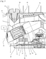
- eine schematische Darstellung eines Zweitaktmotors,
- Fig. 2
- eine Schnittdarstellung eines Ausführungsbeispiels eines Vergasers,
- Fig. 3
- eine ausschnittsweise Seitenansicht des Vergasers aus
Fig. 2 in Richtung des Pfeils III inFig. 2 , - Fig. 4
- eine Schnittdarstellung eines weiteren Ausführungsbeispiels eines Vergasers,
- Fig. 5
- eine ausschnittsweise Schnittdarstellung eines weiteren Ausführungsbeispiels eines Vergasers.
- Fig. 1
- a schematic representation of a two-stroke engine,
- Fig. 2
- a sectional view of an embodiment of a carburetor,
- Fig. 3
- a partial side view of the carburetor
Fig. 2 in the direction of arrow III inFig. 2 , - Fig. 4
- a sectional view of a further embodiment of a carburetor,
- Fig. 5
- a partial sectional view of a further embodiment of a carburetor.
Der in
Der Zweitaktmotor 1 weist einen Ansaugtrakt mit einem Luftfilter 49, einer Gemischbildungseinheit 13 sowie einem Verbindungsstutzen 41 zur Verbindung der Gemischbildungseinheit 13 mit dem Zylinder 2 auf. Die Gemischbildungseinheit 13 ist im Ausführungsbeispiel ein Vergaser. Anstatt des Verbindungsstutzens 41 können ein oder mehrere beliebige andere Teile zur fluidischen Verbindung der Gemischbildungseinheit 13 mit dem Zylinder 2 bzw. dem Kurbelgehäuse 4 vorgesehen sein. Der Luftfilter 49 besitzt ein Filterelement 39. Stromab des Filterelements 39 ist ein Reinraum 50 gebildet, aus dem ein Ansaugkanal 10 führt. In der Gemischbildungseinheit 13 ist ein Ansaugkanalabschnitt 11 ausgebildet. Im Ansaugkanalabschnitt 11 ist ein Drosselelement 17, im Ausführungsbeispiel eine Drosselklappe, verstellbar gelagert. Im Ausführungsbeispiel ist das Drosselelement 17 mit einer Drosselwelle 18 gelagert. Stromab des Drosselelements 17 ist der Ansaugkanal 10 in einen Gemischkanal 12 und einen Luftkanal 14 geteilt. Der Ansaugkanal 10 weist eine Ansaugkanallängsachse 32 auf, die die Längsmittelachse des Ansaugkanals 10 bildet. Der Gemischkanal 12 mündet mit einer Gemischkanalöffnung 15 an der Zylinderbohrung 55. Die Gemischkanalöffnung 15 ist vom Kolben 5 gesteuert. Die Gemischkanalöffnung 15 ist im Bereich des oberen Totpunkts des Kolbens 15 zum Kurbelgehäuseinnenraum 6 hin geöffnet. Der Luftkanal 14 mündet mit mindestens einer Luftkanalöffnung 16 an der Zylinderbohrung 55. Auch die Luftkanalöffnung 16 ist vom Kolben 5 gesteuert. Der Kolben 5 besitzt mindestens eine Kolbentasche 37, die die Luftkanalöffnung 16 im Bereich des oberen Totpunkts des Kolbens 5 mit den Überströmfenstern 9 verbindet. Über den Luftkanal 14, die Luftkanalöffnung 16 und die Überströmfenster 9 wird in den Überströmkanälen 8 im Bereich des oberen Totpunkts des Kolbens 5 Spülvorlagenluft vorgelagert. Der Zylinder 2 weist einen Auslass 40 aus dem Brennraum 3 auf.The two-
Wie
Vorteilhaft ist die Hauptkraftstoffdüse 29 in den Kanal 26 eingepresst. Die Hauptkraftstoffdüse 29 kann dabei unmittelbar in den Kanal 26 eingepresst sein, so dass der Außenumfang der Hauptkraftstoffdüse 29 in Kontakt mit der Wand des Kanals 26 ist. Alternativ kann vorgesehen sein, dass die Hauptkraftstoffdüse 29 unter Zwischenlage mindestens einer Dichtung in den Kanal 26 eingepresst ist. In
Wie
Stromab des Drosselelements 17 ist beim Ausführungsbeispiel nach
Im Betrieb des Zweitaktmotors 1 wird beim Aufwärtshub des Kolbens 5 Kraftstoff/Luft-Gemisch aus dem Gemischkanal 12 in den Kurbelgehäuseinnenraum 6 angesaugt, sobald die Gemischkanalöffnung 15 öffnet. Solange die Luftkanalöffnung 16 über die Kolbentasche 37 mit den Überströmfenstern 9 verbunden ist, wird in den Überströmkanälen 8 Spülvorlagenluft vorgelagert. Beim Abwärtshub des Kolbens 5 wird das Kraftstoff/Luft-Gemisch im Kurbelgehäuseinnenraum 6 komprimiert und, sobald die Überströmfenster 9 öffnen, strömt zunächst Spülvorlagenluft aus den Überströmkanälen 8 und anschließend Kraftstoff/Luft-Gemisch aus dem Kurbelgehäuseinnenraum 6 in den Brennraum 3 ein. Das Kraftstoff/Luft-Gemisch wird beim Aufwärtshub des Kolbens 5 im Brennraum 3 komprimiert und im Bereich des oberen Totpunkts des Kolbens 5 von einer Zündkerze 72 gezündet. Vorzugsweise ist die Zündkerze 72 von einer Steuereinrichtung 61 angesteuert, die auch ein Kraftstoffventil 60 (
Beim Ausführungsbeispiel nach
Auch beim Ausführungsbeispiel nach
Der Kanal 26 weist eine Mittelachse 33 auf. Die Mittelachse 33 schließt im Ausführungsbeispiel mit der Ansaugkanallängsachse 23 einen Winkel α ein, der kleiner als 90° ist. Der Winkel α ist im Ausführungsbeispiel größer als 0°. Auch ein Winkel von 0° kann jedoch vorteilhaft sein. Der Winkel α beträgt vorzugsweise von 0° bis 30°, insbesondere von 0° bis 25°. Der Winkel α ist dabei in einer Schnittebene gemessen, die die Ansaugkanallängsachse 32 enthält und die parallel zur Mittelachse 33 des Kanals 26 verläuft. Im Ausführungsbeispiel enthält die Schnittebene sowohl die Ansaugkanallängsachse 32 als auch die Mittelachse 33 und entspricht der in
Der Grundkörper 23 der Gemischbildungseinrichtung 13 weist eine erste Längsseite 58 und eine zweite Längsseite 59 auf. Die Längsseiten 58 und 59 verlaufen näherungsweise parallel zur Mittelachse 32 des Ansaugkanalabschnitts 11. An der ersten Längsseite 58 ist vorteilhaft eine Kraftstoffpumpe 46 ausgebildet. Die Kraftstoffpumpe 46 wird vom Grundkörper 23, einem am Grundkörper 23 fixierten Pumpendeckel 47 sowie einer nicht dargestellten Pumpenmembran begrenzt. Der Pumpendeckel 47 ist bevorzugt über eine Befestigungsschraube 48 am Grundkörper 23 angeschraubt. An der gegenüberliegenden Längsseite 59 sind vorteilhaft eine Regelkammer 42 und eine Kompensationskammer 43 gebildet, die von einer Regelmembran 44 getrennt sind. Die Regelmembran 44 ist von einem in
Im Kanal 26 ist die Hauptkraftstoffdüse 29 angeordnet. Am Außenumfang der Hauptkraftstoffdüse 29 ist ein Ringspalt 30 gebildet, in den der Kraftstoffkanal 64 mündet. Der Ringspalt 30 wird von einer umlaufenden Nut am Außenumfang der Hauptkraftstoffdüse 29 sowie von der Wand des Kanals 26 begrenzt. In der Hauptkraftstoffdüse 29 ist ein Querkanal 65 ausgebildet, der im Ausführungsbeispiel senkrecht zur Mittelachse 33 verläuft, sowie ein Längskanal 66, der in Richtung der Mittelachse 33 mittig durch die Hauptkraftstoffdüse 29 verläuft. Über den Querkanal 65 ist der Ringspalt 30 mit dem Längskanal 66 verbunden. Der Längskanal 66 mündet an einem Ventilplättchen 52. Das Ventilplättchen 52 bildet mit einem Ventilsitz 54 ein Rückschlagventil 31. In geschlossenem Zustand des Rückschlagventils 31 liegt das Ventilplättchen 52 an dem Ventilsitz 54 an. Bei Überdruck im Ansaugkanalabschnitt 11 gegenüber der Regelkammer 42 ist das Rückschlagventil 31 geschlossen. Bei Unterdruck im Ansaugkanalabschnitt 11 wird das Ventilplättchen 52 vom Ventilsitz 54 abgehoben. Das Rückschlagventil 31 weist einen Anschlag 53 auf, der den maximalen Hub des Ventilplättchens 52 begrenzt. Der Hub des Ventilplättchens 52 ist vorzugsweise möglichst klein.The
In dem Kraftstoffkanal 64, der die Regelkammer 42 mit dem Kanal 26 verbindet, ist im Ausführungsbeispiel ein Rückschlagventil 81 angeordnet. Das Rückschlagventil 81 schließt in Strömungsrichtung vom Kanal 26 zur Regelkammer 42. Das Rückschlagventil 81 ist im Ausführungsbeispiel stromab der Festdrossel 63 angeordnet. Auch eine andere Anordnung des Rückschlagventils 81 kann vorteilhaft sein.In the embodiment, a
Auch eine andere Gestaltung des Kraftstoffventils 60 kann vorteilhaft sein. Anstatt der Hauptkraftstoffdüse 29 oder des Kraftstoffventils 60 können auch andere Bauteile in dem Kanal 26 angeordnet sein. In dem Kanal 26 kann insbesondere ein Nadelventil oder ein federbelastetes Ventil, wie es beispielsweise bei einem Purger verwendet wird, angeordnet sein.Another design of the
Die Gemischbildungseinheit 13 ist in den Ausführungsbeispielen als Vergaser ausgebildet. Ein Vergaser fördert den Kraftstoff aufgrund des im Ansaugkanal bestehenden Unterdrucks in den Ansaugkanal. In alternativer Gestaltung kann auch eine andere Gemischbildungseinheit vorgesehen sein. Die Gemischbildungseinheit kann insbesondere ein Kraftstoffventil aufweisen, das Kraftstoff aufgrund von Überdruck des Kraftstoffs in den Ansaugkanal zuführt, insbesondere in den Ansaugkanal einspritzt.The
Claims (18)
dadurch gekennzeichnet, dass der Kanal (26) an der ersten Stirnseite (24) des Grundkörpers (23) mündet.Mixture formation unit with a base body (23) in which an intake duct section (11) is formed, the intake duct section (11) extending from a first end face (24) of the base body (23) to a second end face (25) of the base body (23) , wherein the mixture formation unit (13) has at least one straight channel (26) which opens into the intake channel section (11),
characterized in that the channel (26) opens out on the first end face (24) of the base body (23).
dadurch gekennzeichnet, dass in dem Kanal (26) ein Bauteil der Gemischbildungseinheit (13) angeordnet ist.Mixture formation unit according to claim 1,
characterized in that a component of the mixture formation unit (13) is arranged in the channel (26).
dadurch gekennzeichnet, dass die Gemischbildungseinheit (13) mindestens eine Kraftstofföffnung aufweist, die in den Ansaugkanalabschnitt (11) mündet und die an einer Kraftstoffdüse ausgebildet ist, wobei die Kraftstoffdüse das in dem Kanal (26) angeordnete Bauteil bildet.Mixture formation unit according to claim 2,
characterized in that the mixture formation unit (13) has at least one fuel opening which opens into the intake duct section (11) and which is formed on a fuel nozzle, the fuel nozzle forming the component arranged in the duct (26).
dadurch gekennzeichnet, dass die Kraftstofföffnung eine Hauptkraftstofföffnung (27) und die Kraftstoffdüse eine Hauptkraftstoffdüse (29) ist.Mixture formation unit according to claim 3,
characterized in that the fuel opening is a main fuel opening (27) and the fuel nozzle is a main fuel nozzle (29).
dadurch gekennzeichnet, dass das Bauteil mit dem Kanal (26) einen Ringspalt (30) bildet, der mit der Kraftstofföffnung verbunden ist.Mixture formation unit according to claim 3 or 4,
characterized in that the component forms an annular gap (30) with the channel (26) which is connected to the fuel opening.
dadurch gekennzeichnet, dass das Bauteil ein Rückschlagventil (31) aufweist.Mixture formation unit according to one of claims 2 to 5,
characterized in that the component has a check valve (31).
dadurch gekennzeichnet, dass das Bauteil ein Kraftstoffventil (60) ist.Mixture formation unit according to one of claims 2 to 5,
characterized in that the component is a fuel valve (60).
dadurch gekennzeichnet, dass die Mittelachse (33) des Kanals (26) mit der Ansaugkanallängsachse (32) in einer Schnittebene, die die Ansaugkanallängsachse (32) enthält und die parallel zur Mittelachse (33) des Kanals (26) verläuft, einen Winkel (α) von 0° bis 30°einschließt.Mixture formation unit according to one of Claims 1 to 7,
characterized in that the central axis (33) of the channel (26) forms an angle (α) with the longitudinal axis (32) of the intake channel in a sectional plane which contains the longitudinal axis (32) of the intake channel and which runs parallel to the central axis (33) of the channel (26) ) from 0 ° to 30 °.
dadurch gekennzeichnet, dass der Ansaugkanalabschnitt (11) einen Venturiabschnitt (34) aufweist und dass stromab des Venturiabschnitts (34) ein Drosselelement (17) im Grundkörper (23) gelagert ist.Mixture formation unit according to one of claims 1 to 8,
characterized in that the intake duct section (11) has a Venturi section (34) and that a throttle element (17) is mounted in the base body (23) downstream of the Venturi section (34).
dadurch gekennzeichnet, dass die erste Stirnseite (24) des Grundkörpers (23) die stromauf liegende Stirnseite des Grundkörpers (23) ist.Mixture formation unit according to claim 9,
characterized in that the first end face (24) of the base body (23) is the upstream end face of the base body (23).
dadurch gekennzeichnet, dass das Drosselelement (17) eine Drosselklappe ist.Mixture formation unit according to claim 9 or 10,
characterized in that the throttle element (17) is a throttle valve.
dadurch gekennzeichnet, dass stromauf des Drosselelements (17) ein Chokeelement (20) im Grundkörper (23) gehalten ist.Mixture formation unit according to claim 11,
characterized in that a choke element (20) is held in the base body (23) upstream of the throttle element (17).
dadurch gekennzeichnet, dass stromauf des Drosselelements (17) kein Trennwandabschnitt im Ansaugkanalabschnitt (11) angeordnet ist.Mixture formation unit according to one of claims 9 to 12,
characterized in that no partition wall section is arranged in the intake duct section (11) upstream of the throttle element (17).
dadurch gekennzeichnet, dass stromauf des Drosselelements (17) ein Trennwandabschnitt (36) im Ansaugkanalabschnitt (11) angeordnet ist.Mixture formation unit according to one of claims 9 to 12,
characterized in that a partition wall section (36) is arranged in the intake duct section (11) upstream of the throttle element (17).
dadurch gekennzeichnet, dass das Bauteil in den Kanal (26) eingepresst ist.Mixture formation unit according to one of claims 1 to 14,
characterized in that the component is pressed into the channel (26).
dadurch gekennzeichnet, dass stromauf des Drosselelements (17) kein Trennwandabschnitt zur Unterteilung des Ansaugkanalabschnitts (11) in den Gemischkanal (12) und den Luftkanal (14) vorgesehen ist.Two-stroke engine according to claim 16,
characterized in that upstream of the throttle element (17) there is no partition section for dividing the intake duct section (11) into the mixture duct (12) and the air duct (14).
dadurch gekennzeichnet, dass stromauf des Drosselelements (17) ein Trennwandabschnitt (36) zur Unterteilung des Ansaugkanalabschnitts (11) in den Gemischkanal (12) und den Luftkanal (14) vorgesehen ist.Two-stroke engine according to claim 16,
characterized in that upstream of the throttle element (17) a partition wall section (36) is provided for dividing the intake duct section (11) into the mixture duct (12) and the air duct (14).
Applications Claiming Priority (1)
| Application Number | Priority Date | Filing Date | Title |
|---|---|---|---|
| DE102019004063.5A DE102019004063A1 (en) | 2019-06-08 | 2019-06-08 | Mixture formation unit and two-stroke engine with one mixture formation unit |
Publications (1)
| Publication Number | Publication Date |
|---|---|
| EP3748151A1 true EP3748151A1 (en) | 2020-12-09 |
Family
ID=70977838
Family Applications (1)
| Application Number | Title | Priority Date | Filing Date |
|---|---|---|---|
| EP20178313.1A Pending EP3748151A1 (en) | 2019-06-08 | 2020-06-04 | Mixture forming unit and two-stroke engine having a mixture forming unit |
Country Status (4)
| Country | Link |
|---|---|
| US (1) | US11384715B2 (en) |
| EP (1) | EP3748151A1 (en) |
| CN (1) | CN112049738A (en) |
| DE (1) | DE102019004063A1 (en) |
Families Citing this family (4)
| Publication number | Priority date | Publication date | Assignee | Title |
|---|---|---|---|---|
| EP3798439A1 (en) * | 2019-09-30 | 2021-03-31 | Andreas Stihl AG & Co. KG | Fuel supply device |
| EP4119782A1 (en) * | 2021-07-15 | 2023-01-18 | Andreas Stihl AG & Co. KG | Fuel supply device and two-stroke engine having a fuel supply device |
| EP4187067A1 (en) * | 2021-11-24 | 2023-05-31 | Winterthur Gas & Diesel Ltd. | Internal combustion engine |
| SE2250643A1 (en) * | 2022-05-30 | 2023-12-01 | Husqvarna Ab | A fuel system module for hand-held powertools |
Citations (5)
| Publication number | Priority date | Publication date | Assignee | Title |
|---|---|---|---|---|
| US1061835A (en) * | 1911-07-24 | 1913-05-13 | Emilio Gobbi | Carbureter. |
| DE10156353A1 (en) * | 2000-11-17 | 2002-05-23 | Walbro Japan Inc | Carburettor with alternating Venturi channel |
| US20140261329A1 (en) | 2013-03-14 | 2014-09-18 | Walbro Engine Management, L.L.C. | Diaphragm carburetor with fuel metering compensation |
| EP2947305A1 (en) * | 2014-05-21 | 2015-11-25 | Yamabiko Corporation | Stratified scavenging two-stroke internal combustion engine and carburetor thereof |
| EP3115572A1 (en) * | 2015-06-24 | 2017-01-11 | Yamabiko Corporation | Stratified scavenging two-stroke internal combustion engine, air cleaner of the same, and intake method |
Family Cites Families (11)
| Publication number | Priority date | Publication date | Assignee | Title |
|---|---|---|---|---|
| US2408726A (en) * | 1943-09-06 | 1946-10-08 | Carter Carburetor Corp | Carburetor |
| DE2523601A1 (en) | 1975-05-28 | 1976-12-09 | Bosch Gmbh Robert | CARBURETOR |
| JPS5554655A (en) * | 1978-10-19 | 1980-04-22 | Nissan Motor Co Ltd | Variable venturi carburetor |
| US5133905A (en) | 1989-10-26 | 1992-07-28 | Walbro Corporation | Fuel metering method and apparatus |
| DE4413270B4 (en) * | 1994-04-16 | 2005-05-04 | Fa. Andreas Stihl | Jump-start device on a diaphragm carburetor |
| CN1678827A (en) * | 2002-07-03 | 2005-10-05 | 彼得·霍尔梅斯·埃尔默斯 | Fluid mixing venturi |
| DE10345653B4 (en) * | 2003-10-01 | 2013-02-28 | Andreas Stihl Ag & Co. Kg | carburetor arrangement |
| DE102005015164B4 (en) * | 2005-04-02 | 2014-04-17 | Andreas Stihl Ag & Co. Kg | Two-stroke engine |
| US10001067B2 (en) * | 2014-02-28 | 2018-06-19 | Walbro Llc | Carburetor with scavenging fluid flow |
| TWM497195U (en) * | 2014-08-22 | 2015-03-11 | hong-sheng Chen | Fuel oil spray nozzle device of air intake system |
| JP6432081B2 (en) * | 2014-11-28 | 2018-12-05 | 株式会社やまびこ | Stratified scavenging engine intake pipe unit |
-
2019
- 2019-06-08 DE DE102019004063.5A patent/DE102019004063A1/en active Pending
-
2020
- 2020-06-04 EP EP20178313.1A patent/EP3748151A1/en active Pending
- 2020-06-05 US US16/894,383 patent/US11384715B2/en active Active
- 2020-06-08 CN CN202010510928.XA patent/CN112049738A/en active Pending
Patent Citations (5)
| Publication number | Priority date | Publication date | Assignee | Title |
|---|---|---|---|---|
| US1061835A (en) * | 1911-07-24 | 1913-05-13 | Emilio Gobbi | Carbureter. |
| DE10156353A1 (en) * | 2000-11-17 | 2002-05-23 | Walbro Japan Inc | Carburettor with alternating Venturi channel |
| US20140261329A1 (en) | 2013-03-14 | 2014-09-18 | Walbro Engine Management, L.L.C. | Diaphragm carburetor with fuel metering compensation |
| EP2947305A1 (en) * | 2014-05-21 | 2015-11-25 | Yamabiko Corporation | Stratified scavenging two-stroke internal combustion engine and carburetor thereof |
| EP3115572A1 (en) * | 2015-06-24 | 2017-01-11 | Yamabiko Corporation | Stratified scavenging two-stroke internal combustion engine, air cleaner of the same, and intake method |
Also Published As
| Publication number | Publication date |
|---|---|
| CN112049738A (en) | 2020-12-08 |
| US20200386192A1 (en) | 2020-12-10 |
| DE102019004063A1 (en) | 2020-12-10 |
| US11384715B2 (en) | 2022-07-12 |
Similar Documents
| Publication | Publication Date | Title |
|---|---|---|
| EP3748151A1 (en) | Mixture forming unit and two-stroke engine having a mixture forming unit | |
| DE102006032475B4 (en) | carburettor | |
| DE102009030593B4 (en) | Carburetor and two-stroke engine with a carburetor | |
| DE102006024078A1 (en) | Combustion engine, comprises suction channel for supplying fuel and combustion air, where suction channel is connected by inlet opening with cleaning area of air filter | |
| DE102006031685B4 (en) | Internal combustion engine and method for its operation | |
| DE102007032526A1 (en) | Carburettor and method for its operation | |
| DE102009015018A1 (en) | internal combustion engine | |
| DE102004056149B4 (en) | two-stroke engine | |
| DE102005015164A1 (en) | Two-stroke engine for e.g. power saw, has fuel flow guiding unit arranged on throttle`s side facing inlet port section to increase speed of fuel flow in area of fuel opening, where guide unit is made up of plastic | |
| DE4130582A1 (en) | MEMBRANE CARBURETTOR | |
| DE3823525A1 (en) | CARBURETTOR FOR COMBUSTION ENGINES | |
| DE102020000989A1 (en) | Two-stroke engine and method of operating a two-stroke engine | |
| DE10301732B4 (en) | Two-stroke engine and method for its operation | |
| DE10009796B4 (en) | Diesel internal-combustion engine diagnosing and/or controlling method, involves determining whether pressure difference of injection interval in opening phase and/or injection interval in closing phase exceeds preset value | |
| DE102013009669B4 (en) | Internal combustion engine with a starting device | |
| DE102013009668B4 (en) | Internal combustion engine with a starting device | |
| DE2541221A1 (en) | CHARGE-FORMING FACILITY | |
| DE10326488A1 (en) | suction | |
| DE102010045017B4 (en) | Two-stroke engine | |
| EP3798439A1 (en) | Fuel supply device | |
| DE10211404A1 (en) | Portable, hand-held implement | |
| EP3584435B1 (en) | Carburetor and hand-held work device with a combustion engine with a carburettor | |
| DE10210892B4 (en) | Two-stroke engine with diaphragm valve integrated in the overflow channel | |
| DE10104446A1 (en) | Internal combustion engine with adjustable CO characteristic | |
| DE2558414C2 (en) | Internal combustion engine with a control system for exhaust emissions |
Legal Events
| Date | Code | Title | Description |
|---|---|---|---|
| PUAI | Public reference made under article 153(3) epc to a published international application that has entered the european phase |
Free format text: ORIGINAL CODE: 0009012 |
|
| STAA | Information on the status of an ep patent application or granted ep patent |
Free format text: STATUS: THE APPLICATION HAS BEEN PUBLISHED |
|
| AK | Designated contracting states |
Kind code of ref document: A1 Designated state(s): AL AT BE BG CH CY CZ DE DK EE ES FI FR GB GR HR HU IE IS IT LI LT LU LV MC MK MT NL NO PL PT RO RS SE SI SK SM TR |
|
| AX | Request for extension of the european patent |
Extension state: BA ME |
|
| STAA | Information on the status of an ep patent application or granted ep patent |
Free format text: STATUS: REQUEST FOR EXAMINATION WAS MADE |
|
| 17P | Request for examination filed |
Effective date: 20210607 |
|
| RBV | Designated contracting states (corrected) |
Designated state(s): AL AT BE BG CH CY CZ DE DK EE ES FI FR GB GR HR HU IE IS IT LI LT LU LV MC MK MT NL NO PL PT RO RS SE SI SK SM TR |
|
| STAA | Information on the status of an ep patent application or granted ep patent |
Free format text: STATUS: EXAMINATION IS IN PROGRESS |
|
| 17Q | First examination report despatched |
Effective date: 20220908 |