EP3747794B1 - Ausgabeverschluss - Google Patents
Ausgabeverschluss Download PDFInfo
- Publication number
- EP3747794B1 EP3747794B1 EP20188726.2A EP20188726A EP3747794B1 EP 3747794 B1 EP3747794 B1 EP 3747794B1 EP 20188726 A EP20188726 A EP 20188726A EP 3747794 B1 EP3747794 B1 EP 3747794B1
- Authority
- EP
- European Patent Office
- Prior art keywords
- closure
- locking member
- closure body
- actuator
- dispensing
- Prior art date
- Legal status (The legal status is an assumption and is not a legal conclusion. Google has not performed a legal analysis and makes no representation as to the accuracy of the status listed.)
- Active
Links
- 239000000126 substance Substances 0.000 claims description 38
- 238000004891 communication Methods 0.000 claims description 4
- 239000011324 bead Substances 0.000 description 21
- 230000013011 mating Effects 0.000 description 10
- 239000000463 material Substances 0.000 description 8
- -1 polyethylene terephthalate Polymers 0.000 description 8
- 230000009471 action Effects 0.000 description 7
- 238000004519 manufacturing process Methods 0.000 description 5
- 238000000034 method Methods 0.000 description 5
- 230000000881 depressing effect Effects 0.000 description 4
- 210000003811 finger Anatomy 0.000 description 4
- 238000007789 sealing Methods 0.000 description 4
- 239000004698 Polyethylene Substances 0.000 description 3
- 239000000853 adhesive Substances 0.000 description 3
- 230000001070 adhesive effect Effects 0.000 description 3
- 229920000573 polyethylene Polymers 0.000 description 3
- 238000005381 potential energy Methods 0.000 description 3
- 239000004743 Polypropylene Substances 0.000 description 2
- 239000006071 cream Substances 0.000 description 2
- 235000013305 food Nutrition 0.000 description 2
- 210000005224 forefinger Anatomy 0.000 description 2
- 239000006210 lotion Substances 0.000 description 2
- 230000014759 maintenance of location Effects 0.000 description 2
- 229920000139 polyethylene terephthalate Polymers 0.000 description 2
- 239000005020 polyethylene terephthalate Substances 0.000 description 2
- 229920001155 polypropylene Polymers 0.000 description 2
- 210000003813 thumb Anatomy 0.000 description 2
- 241001465754 Metazoa Species 0.000 description 1
- 238000009825 accumulation Methods 0.000 description 1
- 230000004075 alteration Effects 0.000 description 1
- XAGFODPZIPBFFR-UHFFFAOYSA-N aluminium Chemical compound [Al] XAGFODPZIPBFFR-UHFFFAOYSA-N 0.000 description 1
- 229910052782 aluminium Inorganic materials 0.000 description 1
- 239000012080 ambient air Substances 0.000 description 1
- 230000009286 beneficial effect Effects 0.000 description 1
- 238000004140 cleaning Methods 0.000 description 1
- 230000003749 cleanliness Effects 0.000 description 1
- 238000010276 construction Methods 0.000 description 1
- 239000003814 drug Substances 0.000 description 1
- 230000000694 effects Effects 0.000 description 1
- 230000002708 enhancing effect Effects 0.000 description 1
- 239000000945 filler Substances 0.000 description 1
- 239000012530 fluid Substances 0.000 description 1
- 239000011888 foil Substances 0.000 description 1
- 239000000499 gel Substances 0.000 description 1
- 239000008187 granular material Substances 0.000 description 1
- 238000001746 injection moulding Methods 0.000 description 1
- 238000009434 installation Methods 0.000 description 1
- 230000001788 irregular Effects 0.000 description 1
- 239000007788 liquid Substances 0.000 description 1
- 238000012423 maintenance Methods 0.000 description 1
- 230000007246 mechanism Effects 0.000 description 1
- 238000012986 modification Methods 0.000 description 1
- 230000004048 modification Effects 0.000 description 1
- 238000000465 moulding Methods 0.000 description 1
- 239000003921 oil Substances 0.000 description 1
- 239000004033 plastic Substances 0.000 description 1
- 229920003023 plastic Polymers 0.000 description 1
- 239000000843 powder Substances 0.000 description 1
- 230000002028 premature Effects 0.000 description 1
- 238000012545 processing Methods 0.000 description 1
- 238000012552 review Methods 0.000 description 1
- 238000007788 roughening Methods 0.000 description 1
- 229920001169 thermoplastic Polymers 0.000 description 1
- 239000012815 thermoplastic material Substances 0.000 description 1
- 238000003466 welding Methods 0.000 description 1
Images


Classifications
-
- B—PERFORMING OPERATIONS; TRANSPORTING
- B65—CONVEYING; PACKING; STORING; HANDLING THIN OR FILAMENTARY MATERIAL
- B65D—CONTAINERS FOR STORAGE OR TRANSPORT OF ARTICLES OR MATERIALS, e.g. BAGS, BARRELS, BOTTLES, BOXES, CANS, CARTONS, CRATES, DRUMS, JARS, TANKS, HOPPERS, FORWARDING CONTAINERS; ACCESSORIES, CLOSURES, OR FITTINGS THEREFOR; PACKAGING ELEMENTS; PACKAGES
- B65D47/00—Closures with filling and discharging, or with discharging, devices
- B65D47/04—Closures with discharging devices other than pumps
- B65D47/06—Closures with discharging devices other than pumps with pouring spouts or tubes; with discharge nozzles or passages
- B65D47/08—Closures with discharging devices other than pumps with pouring spouts or tubes; with discharge nozzles or passages having articulated or hinged closures
-
- B—PERFORMING OPERATIONS; TRANSPORTING
- B65—CONVEYING; PACKING; STORING; HANDLING THIN OR FILAMENTARY MATERIAL
- B65D—CONTAINERS FOR STORAGE OR TRANSPORT OF ARTICLES OR MATERIALS, e.g. BAGS, BARRELS, BOTTLES, BOXES, CANS, CARTONS, CRATES, DRUMS, JARS, TANKS, HOPPERS, FORWARDING CONTAINERS; ACCESSORIES, CLOSURES, OR FITTINGS THEREFOR; PACKAGING ELEMENTS; PACKAGES
- B65D47/00—Closures with filling and discharging, or with discharging, devices
- B65D47/04—Closures with discharging devices other than pumps
- B65D47/20—Closures with discharging devices other than pumps comprising hand-operated members for controlling discharge
- B65D47/2006—Closures with discharging devices other than pumps comprising hand-operated members for controlling discharge formed by a rigid spout outlet opened by tilting of the spout outlet
-
- B—PERFORMING OPERATIONS; TRANSPORTING
- B65—CONVEYING; PACKING; STORING; HANDLING THIN OR FILAMENTARY MATERIAL
- B65D—CONTAINERS FOR STORAGE OR TRANSPORT OF ARTICLES OR MATERIALS, e.g. BAGS, BARRELS, BOTTLES, BOXES, CANS, CARTONS, CRATES, DRUMS, JARS, TANKS, HOPPERS, FORWARDING CONTAINERS; ACCESSORIES, CLOSURES, OR FITTINGS THEREFOR; PACKAGING ELEMENTS; PACKAGES
- B65D50/00—Closures with means for discouraging unauthorised opening or removal thereof, with or without indicating means, e.g. child-proof closures
- B65D50/02—Closures with means for discouraging unauthorised opening or removal thereof, with or without indicating means, e.g. child-proof closures openable or removable by the combination of plural actions
- B65D50/06—Closures with means for discouraging unauthorised opening or removal thereof, with or without indicating means, e.g. child-proof closures openable or removable by the combination of plural actions requiring the combination of different actions in succession
-
- B—PERFORMING OPERATIONS; TRANSPORTING
- B65—CONVEYING; PACKING; STORING; HANDLING THIN OR FILAMENTARY MATERIAL
- B65D—CONTAINERS FOR STORAGE OR TRANSPORT OF ARTICLES OR MATERIALS, e.g. BAGS, BARRELS, BOTTLES, BOXES, CANS, CARTONS, CRATES, DRUMS, JARS, TANKS, HOPPERS, FORWARDING CONTAINERS; ACCESSORIES, CLOSURES, OR FITTINGS THEREFOR; PACKAGING ELEMENTS; PACKAGES
- B65D51/00—Closures not otherwise provided for
- B65D51/24—Closures not otherwise provided for combined or co-operating with auxiliary devices for non-closing purposes
- B65D51/248—Closures not otherwise provided for combined or co-operating with auxiliary devices for non-closing purposes the closure being provided with transient audible or visual signaling means, e.g. for indicating dispensing, or other illuminating or acoustic devices, e.g. whistles
-
- B—PERFORMING OPERATIONS; TRANSPORTING
- B65—CONVEYING; PACKING; STORING; HANDLING THIN OR FILAMENTARY MATERIAL
- B65D—CONTAINERS FOR STORAGE OR TRANSPORT OF ARTICLES OR MATERIALS, e.g. BAGS, BARRELS, BOTTLES, BOXES, CANS, CARTONS, CRATES, DRUMS, JARS, TANKS, HOPPERS, FORWARDING CONTAINERS; ACCESSORIES, CLOSURES, OR FITTINGS THEREFOR; PACKAGING ELEMENTS; PACKAGES
- B65D2203/00—Decoration means, markings, information elements, contents indicators
- B65D2203/12—Audible, olfactory or visual signalling means
Definitions
- the present invention relates generally to a dispensing closure for a container or other system that contains a fluent substance.
- Closures are employed to selectively prevent or permit communication between the exterior and interior of a system (e.g., machine, equipment, containment system (including containers such as bottles and pouches), etc.) through an opening in the system.
- a typical closure includes at least (1) a receiving structure (e.g., a body, base, fitment, etc.) at an opening to the system interior, and (2) a closing element (e.g., a lid, cover, overcap, pivotable disc top type actuator, etc.) that is cooperatively received by the receiving structure.
- the receiving structure of the closure can typically be either (1) a separate structure that (a) can be attached at such a system opening, and (b) defines at least one passage through the receiving structure for communicating through such a system opening with the interior of such a system, or (2) an integral structure that is a unitary portion of such a system and that defines at least one passage through the integral structure such that the passage functions as the opening, per se , to the system.
- the closing element typically is movable relative to the receiving structure passage between (1) a fully closed position occluding the passage, and (2) an open position at least partially exposing the passage.
- Some closures may include additional elements (e.g., tamper-evident features, locking elements, etc.).
- a closure specifically designed for dispensing a fluent substance may be described as a dispensing closure.
- Various fluent materials or substances may be packaged in a rigid, flexible, or collapsible container having a dispensing closure that can be opened and closed.
- a flexible container may be pressurized by a user to force the fluent substance from the container and through the closure body to dispense the fluent substance at a target region or onto a target surface area. If the container is a bottle, pouch, or other such container, then such a container with the closure mounted thereon and the contents stored therein may be characterized as a "package.”
- One type of dispensing closure is a toggle action type, which typically is provided with a closing element in the form of a generally flat, disc top type actuator or a domed type actuator for dispensing a fluent substance.
- a user of such a closure will typically encounter the actuator in a closed, non-dispensing position.
- the actuator may be provided with a region for being pressed upon by a user of the closure to toggle, tilt, pivot, or otherwise rotate the actuator with respect to a stationary portion of the closure (e.g., closure body), moving the actuator from the closed position into an open position such that a fluent substance may be dispensed through the closure.
- Such an actuator may subsequently be pressed upon by a user, at a different region of the actuator, to toggle, pivot, or otherwise rotate the actuator back into the closed, non-dispensing position.
- Such closures of the prior art are e.g. described in US 5 379 926 A , disclosing a dispensing closure with a closure body, a locking member and an actuator essentially according to the preamble portion of claim 1, or in US 5 314 093 A .
- toggle action type closures when installed in or on a system (e.g., a container of a fluent substance), may be susceptible to inadvertent opening during manufacturing, shipping, or handling, which can result in premature or messy leaking of the fluent substance from the closure.
- Inadvertent opening of such a closure may be prevented, or at least minimized, by applying an adhesive seal or a film wrap around at least a portion of the closure to mechanically prevent movement of the actuator until the seal or wrap has been removed by a user of the closure.
- Such additional seals or wraps may increase the cost of the closure, require additional manufacturing steps, or present a nuisance to the user who must remove such a seal or wrap.
- the inventor of the present invention has determined that it would be desirable to provide an improved toggle action dispensing closure for preventing inadvertent opening of the closure.
- the inventor of the present invention has further determined that it would be beneficial to provide an improved toggle action dispensing closure that would facilitate repeatable and easy locking and unlocking of the closure by a user.
- the inventor of the present invention has also determined that, in many applications, it may be desirable to provide an improved toggle action dispensing closure as part of a package wherein the closure structure facilitates or accommodates the cleaning of the closure and/or minimizes the potential for accumulation of residue, dirt, grime, etc. during the useful life of the package.
- the inventor of the present invention has also determined that it would be desirable to provide an improved toggle action dispensing closure that can be configured for use with a container of a fluent substance so as to have one or more of the following advantages: (1) an improved ease of manufacture and/or assembly, and (ii) a reduced cost of manufacture and/or assembly.
- the inventor of the present invention has invented a novel structure for a toggle action dispensing closure for use with a system, which could be a container or other type of system, wherein the closure includes various advantageous features not heretofore taught or contemplated by the prior art.
- a dispensing closure for a system having an opening between an exterior of the system and an interior of the system where a fluent substance may be stored.
- the dispensing closure has a closure body that can be located at the system opening and that defines an inlet for communicating with the system.
- the closure body further has an end defining an aperture to accommodate the flow of a fluent substance through the closure body.
- the dispensing closure has a locking member mounted on the closure body for rotation about a central rotational axis.
- the locking member has an intermediate flow passage for accommodating the flow of a substance through the closure body aperture.
- the locking member has a locking position, and an unlocking position rotated about the central rotational axis away from the locking position.
- the dispensing closure has an actuator that is rotatably mounted to the locking member for occluding the locking member intermediate flow passage to prevent flow of a fluent substance through the closure when the actuator is in a closed, non-dispensing position and for permitting flow of a fluent substance through the closure when the actuator is rotated to an open, dispensing position.
- the actuator includes a dispensing flow passage that is in communication with the intermediate flow passage of the locking member when the actuator is in the open, dispensing position. The actuator is in engagement with a portion of the closure body when the locking member is in the locking position to prevent the actuator from moving into the open, dispensing position.
- the closure body is adapted for use with a system that is a container defining the opening and the closure body is one of: a separate structure for being attached to the container at the container opening; and an integral structure that is a unitary part of a container formed at the container opening.
- the end of the closure body includes a top deck defining an upper surface
- the locking member includes a bottom deck defining a bottom surface confronting the closure body upper surface
- the dispensing closure aperture of has a configuration centered on the central rotational axis and at least a portion of the intermediate flow passage of the locking member is offset from the central rotational axis.
- the actuator includes at least one downwardly extending abutment and the closure body includes an upwardly extending abutment whereby the downwardly-extending abutment and the upwardly extending abutment are oriented to engage to prevent the actuator from moving into the open, dispensing position when the locking member is in the locking position.
- the locking member includes a bottom deck defining an aperture and the upwardly extending abutment of the closure body extends through the aperture.
- the upwardly extending abutment of the closure body has a radius of curvature centered on the central rotational axis
- the downwardly extending abutment of the actuator has a length extending an oblique angle relative to the radius of curvature
- the closure body has at least one retaining projection extending upwardly from the closure body end, and the locking member has at least one arcuate slot therein for receiving the retaining projection.
- the closure body has a plurality of circumferentially-spaced retaining projections
- the locking member has a plurality of circumferentially-spaced arcuate slots therein, each one of the arcuate slots receiving a different one of the retaining projections.
- the end of said closure body has an upper surface with at least one recess therein.
- the locking member has at least one resilient projection having a bead. Rotation of the locking member relative to the closure body carries the projection in an arc with the bead engaging the surface so that the projection is deflected by the surface. Continued rotation of the locking member relative to the closure body carries the projection to a location in which the at least one recess receives the bead, whereupon the projection returns to its undeflected condition as the bead snaps into the at least one recess to generate at least one of an audible signal and a tactile signal.
- the closure body has at least one projection extending therefrom.
- the locking member has at least one resilient, deflectable tab extending therefrom, whereby rotation of the locking member relative to the closure body moves the projection against and past the tab which deflects and returns to its undeflected condition to generate at least one of an audible signal and a tactile signal.
- the closure body has at least one indicium
- the locking member has at least one indicium that cooperate to indicate whether the locking member is in one of the locking position and the unlocking position.
- the locking member is rotatable less than 45 degrees about the central rotational axis between the locking position and the unlocking position.
- the closure body further includes an upwardly extending wall surrounding and defining at least a portion of the aperture
- the locking member includes a downwardly extending wall sealingly engaged with the closure body upwardly extending wall
- the actuator includes a pair of oppositely extending protrusions
- the locking member includes an outer wall having a pair of facing recesses therein to each receive a different one of the protrusions.
- the locking member includes a bottom deck having a plurality of circumferentially-spaced arcuate slots therein, each of the slots having the same radius of curvature.
- the bottom deck includes an arcuate aperture having a radius of curvature less than the radius of curvature of the slots.
- the locking member includes a raised central deck and a spout extending upwardly from the raised central deck.
- the intermediate flow passage extends through the raised central deck and the spout.
- the closure body end includes an upwardly extending wall and the locking member defines an annular channel for receiving the wall.
- the dispensing closure is in combination with a system that is a container of a fluent substance.
- the closure and container together defining a package.
- axially outwardly refers to the opposite direction along the central rotational axis "A" toward the top of the closure and away from the container interior. It will be understood, however, that the closure of this invention may be manufactured, stored, transported, used, and sold in an orientation other than the orientation described.
- the dispensing closure, or simply closure, of this invention is especially suitable for use with, among other things, a variety of conventional or special systems, including containers, the details of which, although not fully illustrated or described, would be apparent to those having skill in the art and an understanding of such containers.
- the particular container, per se, that is illustrated and described herein forms no part of, and therefore is not intended to limit, the present invention. It will also be understood by those of ordinary skill that novel and non-obvious inventive aspects are embodied in the described exemplary closures alone.
- the closures described herein are especially suitable for use on a container that contains a fluent material or substance in the form of a lotion or cream that can be dispensed, or otherwise discharged, from the container through the opened closure.
- fluent substances may be, for example, a personal care product, a food product, an industrial product, a household product, or other types of products.
- Such substances may be for internal or external use by humans or animals, or for other uses (e.g., activities involving medicine, manufacturing, commercial or household maintenance, construction, agriculture, etc.).
- FIGS. 1-30 A first embodiment of a closure of the present invention, and the components thereof, are illustrated in FIGS. 1-30 , wherein the closure is designated generally by the reference number 40.
- the closure 40 is provided in the form of a separate article which is configured to be attached or assembled to a system such as a container 44 that would typically contain a fluent substance.
- the container 44 may be any conventional type, such as a collapsible, flexible pouch, or may be a generally rigid container that has somewhat flexible, resilient walls, such as a bottle or tank.
- FIG. 1 shows an embodiment of the closure 40 attached to a container 44 that is a generally rigid bottle having a wall that is somewhat flexible and that can be squeezed by the user to dispense a product when the closure 40 is opened.
- the closure 40 may instead be used on a larger dispensing system (not illustrated) which may include, or be part of, for example, a medical device, processing machine, dispenser, reservoir on a machine, etc., wherein the system has an opening to the system interior.
- the container 44 may be made from a material suitable for the intended application (e.g., a thin, flexible material for a pouch (wherein such a material could be a polyethylene terephthalate (PET) film or a polyethylene film and/or an aluminum foil), or a thicker, less flexible material such as molded polyethylene or polypropylene for a more rigid container 44 such as a bottle).
- a material suitable for the intended application e.g., a thin, flexible material for a pouch (wherein such a material could be a polyethylene terephthalate (PET) film or a polyethylene film and/or an aluminum foil), or a thicker, less flexible material such as molded polyethylene or polypropylene for a more rigid container 44 such as a bottle).
- the closure 40 is mounted to a container 44 such as a bottle or pouch (not illustrated)
- a container 44 such as a bottle or pouch
- the closure manufacturer will then ship the closure 40 to a container filler facility at another location where the container 44 is either manufactured or otherwise provided, and where the container 44 is filled with a product prior to installation of the closure.
- the closure may include a suitable fitment portion that can be attached to the pouch as the pouch is being made and filled, or as the pouch is being made but before the pouch is subsequently filled through the open closure or through open regions of the pouch walls that are later sealed closed.
- the closure 40 is provided as a separately manufactured article, component, or unit for being screwed onto the container 44. It will be appreciated, however, that in some applications, it may be desirable for the closure 40 to be attached to a container in a manner that would not allow a user to easily remove the closure 40. Further, it may be desirable for the closure (or at least the body of the closure) to be formed as a unitary part, or extension, of the container (e.g., a bottle) wherein such a unitary part or extension also (i.e., simultaneously) defines an end structure of the container, per se.
- the first illustrated embodiment of the closure 40 if initially formed separately from the container 44, is adapted to be attached to the container 44 at an opening in the container which provides access to the container interior and to the fluent contents contained therein after a portion of the closure 40 is opened as described hereinafter.
- the container 44 per se, such as a bottle, pouch, or other container, per se, does not form a part of the broadest aspects of the present invention.
- the container, or other system may have any suitable configuration.
- the bottle typically includes an upper end portion 46 (or other suitable structure on some part of the bottle) that defines the bottle mouth or opening and a threaded portion (or snap-fit bead, not illustrated) for mating with a cooperating threaded portion (or snap-fit bead, not illustrated) of the closure 40, which is discussed in detail hereinafter.
- the bottle upper end portion 46 typically has a cross-sectional configuration with which the closure 40 is adapted to engage.
- Extending from the upper end portion 46 is a main body portion 50 of the bottle.
- the main body portion 50 has a cross-sectional configuration that differs from the cross-sectional configuration of the bottle upper end portion 46 at the bottle opening.
- the bottle may instead have a substantially uniform shape along its entire length or height without any portion of reduced size or different cross-section.
- the first embodiment of the closure 40 illustrated in the FIGS. 1-30 is especially suitable for use with a container 44 that is a bottle having a substantially flexible wall or walls that can be squeezed or deflected laterally inwardly by the user to increase the internal pressure within the bottle so as to force the fluent substance out of the bottle and through the opened closure 40.
- the walls have sufficient, inherent resiliency so that when the squeezing forces are removed, the bottle walls return to the normal, unstressed shape.
- a generally rigid container and to pressurize the container interior at selected times with a piston or other pressurizing system (not illustrated), or to reduce the exterior ambient pressure so as to suck the material out through the open closure.
- the closure 40 may be used with a product containment system or other type of system (not illustrated), where the closure 40 can function to permit or prevent the egress or ingress of substances relative to the system in which the closure 40 is installed.
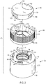
- the closure 40 includes the following basic components: a base or closure body 54, a twist collar or locking member 56, and an actuator 60.
- An optional cap or lid (not illustrated) could be provided for being removably mounted atop of the closure 40.
- the closure body 54, the locking member 56, and the actuator 60 are preferably formed or molded as separate structures and subsequently assembled together.
- the closure body 54, the locking member 56, and the actuator 60 are each preferably molded from a suitable thermoplastic material such as polyethylene or polypropylene. Other materials may be employed instead. It will be understood that in alternative designs (not illustrated), two or more of the three basic components may be unitarily formed or molded together initially as one connected structure, and then substantially broken apart, and then assembled in an operative combination. Further, it will be understood that the closure body 54 may be unitarily formed or molded as an extension of the upper end of the container 44.
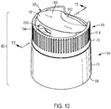
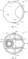
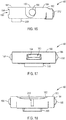
- the actuator 60 is movable between an open position ( FIG. 10 ) and a closed position ( FIG. 1 ), and the actuator 60 can be "locked” in the closed position when the locking member 56 is rotated to a locking position from an unlocking position ( FIG. 3 ).
- the closure body 54 includes an inlet portion or lower end 68 and an upper end 70.
- a cylindrical skirt or outer wall 71 extends between the lower end 68 and the upper end 70.
- the lower end 68 defines an inlet (e.g., passage) 74 ( FIG. 5 ) for being located at the opening of the bottle 44 ( FIG. 1 ) to communicate with an interior of the bottle 44 containing a fluent substance.
- a pair of indicia 72 are located on the outer wall 71, proximal the upper end 70.
- the indicia 72 function together with an indicium located on the locking member 56 to indicate relative rotation between the closure body 54 and the locking member 56 about the central rotation axis "A" ( FIG. 5 ), as discussed in detail below.
- the interior of the closure body 54 is provided with a plurality of internal threads 76 extending radially inwardly therefrom.
- the internal threads 76 cooperate with, and threadingly engage, mating external threads on the container (not visible in FIG. 1 ) to securely attach the closure body 54 together with the container 44 ( FIG. 1 ) at the opening of the container 44.
- other conventional or special means of connecting the closure body 54 to the container 44 could be employed, such as mating snap-fit beads, bi-injection molding, adhesives, mechanical locks, spin welding of the closure to the container, etc.
- closure body 54 is to be used on a flexible pouch (not illustrated), then it is presently contemplated that the closure body lower end 68 would have a suitable boat-shaped fitment configuration (e.g., such as that shown in PCT/US2013/043065 ) for being sealed with the pouch, and most pouch manufacturers will prefer to install the closure body lower end at an opening formed in the pouch with heat sealing techniques or ultrasonic sealing techniques.
- a suitable boat-shaped fitment configuration e.g., such as that shown in PCT/US2013/043065
- the closure body wall 71 terminates at a top deck 80 at the upper end 70.
- the top deck 80 has an exterior surface or upper surface 82.
- the top deck 80 further has a circular, central hole or aperture 84 ( FIGS. 2 and 26 ).
- the aperture 84 opens to (i.e., communicates with) the interior of the closure body 54 which defines the inlet passage 74 ( FIG. 11 ).
- the aperture 84 in the closure body deck 80 is defined in part by (1) a circular, upwardly-extending rim or wall 86 having a radially-inwardly extending bead 87 thereon, and (2) a circular, downwardly-extending rim or wall 88.
- Each of the walls 86 and 88 assists in retaining an annular mating feature of the locking member 56 within the aperture 84, the details of which are discussed below.
- closure body 54 is illustrated as having a generally cylindrical structure, it will be appreciated, however, that the closure body 54 may take a variety of forms, and need not be limited to a cylindrical shape and need not have circular cross-sections as shown.
- the lower end 68 and/or the upper end 70 may be elliptical, polygonal, or some irregular shape.
- the upper surface 82 of the top deck 80 is provided with a pair of hemispherical recesses 90 therein, which are spaced apart along a circumference centered on the central rotational axis "A".
- the hemispherical recesses 90 accommodate a mating protrusion on the locking member 56 discussed hereinafter to generate or produce an audible and/or tactile indication to a user of the closure 40 when the locking member 56 is rotated with respect to the closure body 54.
- three generally arcuate lugs or retaining projections 94 are circumferentially spaced apart and extend upwardly from the upper surface 82 of the top deck 80.
- each one of the retaining projections 94 terminates in a radially-outwardly extending flange 98 defining a flat lower surface 102 and a frusto-conical, sloping upper surface 106, the function of which will be discussed in detail hereinafter.
- retaining projections 94 are provided for mating with (i.e., being received in) three arcuate slots in the locking member 56 in the illustrated first embodiment of the closure 40, it will be understood that more or fewer retaining projections 94 and mating slots may be provided to either increase or decrease, respectively, the rigidity of the connection holding together the locking member 56 to the closure body 54.
- the closure body 56 is further provided with an arcuate locking tab or abutment 110 extending upwardly from the upper surface 82 of the top deck 80.
- the abutment 110 serves to contact a mating feature of the actuator 60 to prevent the actuator 60 from moving into an open, dispensing position when the locking member 56 is in a locking position as will be discussed below.
- the abutment 110 extends axially outwardly beyond the three retaining projections 94, and extends through a unique, larger arcuate aperture within the locking member 56 as discussed hereinafter.
- each projection defines an arc of a circle
- the radially innermost portion of the abutment 110 defines an arc of a circle.
- the interior radius of curvature "R1" of the abutment 110 is less than the interior radius of curvature "R2" of each of the three retaining projections 94.
- each one of the three retaining projections 94 and the abutment 110 lie within a different quadrant of the closure body 54, when the closure body 54 is viewed from above.
- the shorter radius of curvature "R1" assists in preventing undesirable interference between the abutment 110 and the actuator 60 when the locking member 56 is rotated into the unlocked position, as will be discussed in detail hereinafter.
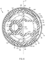
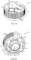
- the locking member 56 is generally ring-shaped and has an annular, outer wall 114, a generally annular, bottom deck 118 that extends radially inwardly from the bottom portion of the outer wall 114, and a raised central deck 119 ( FIG. 5 ).
- the bottom deck 118 of the locking member 56 defines a top surface 120 ( FIGS. 19 and 21 ) facing toward the actuator 60 ( FIG. 2 ) and a bottom surface 121 ( FIGS. 20 and 22 ) facing toward the closure body 54 ( FIG. 2 ).
- the bottom deck 118 is further provided with three arcuate retention slots 122 ( FIGS. 20-22 ) therein. Each slot 122 receives a separate one of the closure body retaining projections 94 ( FIG.
- each locking projection flange 98 extends radially outwardly over, and confronts, the upper surface 120 of the locking member bottom deck 118.
- the bottom deck 118 of the locking member 56 is further provided with an arcuate aperture 126 to receive the abutment 110 ( FIG. 5 ) when the locking member 56 is assembled together with the closure body 54 ( FIG. 5 ).
- the shape of the aperture 126 accommodates the travel of the abutment 110 though an arc of about 30 degrees, with respect to axis "A", when the locking member 56 is rotated relative to the closure body 54 between a locking position ( FIG. 3 ) and an unlocking position ( FIG. 7 ).
- the aperture 126 is larger than the slots 122 to ensure proper assembly of the locking member 56 together with the closure body 54.
- annular recess or channel 130 which surrounds a downwardly-extending annular wall 134.
- the annular channel 130 functions to receive the annular, upwardly-extending wall 86 ( FIG. 5 ) of the closure body 54 while the annular wall 134 of the locking member 56 fits within the closure body flow aperture 84 ( FIG. 2 ) defined by the closure body annular walls 86 and 88 ( FIG. 5 ).
- the locking member annular wall 134 engages the bead 87 ( FIG.
- the wall 134 is provided with a tapered end surface 136 to assist in seating of the wall 134 within the aperture 84 during assembly of the components by the manufacturer.
- the locking member 56 includes a cylindrical spout 138 that extends upwardly from the deck 118.
- the upwardly extending spout 138 and the downwardly extending annular wall 134 together define an intermediate flow passage 140 that extends through both the spout 138 and the wall 134.
- the spout 138 is centered on an axis "B" ( FIGS. 5 and 8 ) that is offset from the central axis "A" about which the wall 134 is centered.
- the fluent substance from the outlet end of the container 44 within the inlet passage 74 of the closure body 54 ( FIG. 5 ) flows through the closure body 54 and into the locking member 56 through the intermediate flow passage 140.
- the inside of the annular wall 114 of the locking member 56 is provided with a pair of opposing detents or hemispherical recesses 144 that serve to retain mating hemispherical protrusions or trunnions formed on oppositely-facing sides of the actuator 60 as discussed in detail below.
- the external surface of the locking member annular wall 114 has a plurality of axially-extending channels 148 therein for enhancing the friction between a user's fingers (e.g., thumb and forefinger) and the surface of the locking member 56 during the locking and unlocking rotation of the closure 40.
- a rear portion of the wall 114 includes a cut-away or recessed area 152 ( FIGS. 2 , 3 , 7 , and 19 ) to accommodate a user's finger (e.g., thumb or forefinger) during actuation of the actuator 60, as will be discussed herein.
- Other types of friction-enhancing means may be utilized, in place of the channels 148, such as providing the wall 114 with surface roughening, finger recesses, raised beads, etc.
- the annular wall 114 of the locking member 56 has an indicium 156 in the form of an arrow pointing toward the closure body 54.
- the indicium 156 is located on the annular wall 114 such that the arrow points either toward the unlocked or locked indicia 72 on the closure body 54 at the two limits of relative rotation between the locking member 56 and the closure body 54, thus indicating to a user of the closure 40 the unlocked or locked status of the closure 40.
- a U-shaped cut aperture or through hole 160 is provided within the annular bottom deck 118 to define a radially-inwardly extending projection 164 ( FIG. 21 ).
- the projection 164 has a downwardly-extending bump or hemispherical bead 168 ( FIGS. 20 and 22 ) formed thereon.
- the bead 168 moves with respect to the closure body recesses 90 ( FIG. 26 ) to produce an audible and/or tactile signal for the user of the closure 40.
- This audible and/or tactile signal mechanism are discussed hereinafter.
- the locking member 56 includes a central rib 170 that bisects the locking member 56 when viewed from above.
- the central rib 170 extends between opposite sides of the annular wall 114, beneath the hemispherical recesses 144 ( FIG. 2 ).
- the central rib 170 strengthens the locking member 56 and also functions to support the actuator 60 during pivoting movement of the actuator 60 with respect to the locking member 56, and to prevent undesirable vertical movement of the locking member 56 with respect to the actuator 60 during pivoting thereof, as will be discussed in detail hereinafter.
- the actuator 60 has a generally disc-like shape with a substantially flat top end 180 with a front region 181 and a recessed or sloping back region 182 designed to accommodate the finger of a user of the closure 40 during opening of the actuator 60.
- the actuator 60 has an annular side wall 184 with a pair of semispherical protrusions 188 spaced 180 degrees apart from one another. Each one of the protrusions 188 fits within one of the recesses 144 ( FIG. 6 ) in the locking member 56 ( FIG. 6 ) to define a pivot axis "P" ( FIG. 6 ) about which the actuator 60 may pivot with respect to the locking member 56, the operation of which is discussed hereinafter.
- the actuator 60 is provided with a dispensing flow passage 190 having an inlet end 192 ( FIG. 13 ) and an outlet end 194 ( FIG. 12 ) on the exterior of the actuator 60.
- the actuator dispensing flow passage 190 may be selectively placed into communication with the intermediate flow passage 140 ( FIG. 11 ) of the locking member 56 ( FIG. 11 ) when the actuator 60 is pivoted from a closed position ( FIG. 8 ) to an open position ( FIG. 11 ) by a user of the closure 40.
- the actuator 60 has a plug or internal annular wall 200 that extends downwardly therefrom to seal against the inside of the spout 138 ( FIG.
- a first semi-circular sealing rim 204 and a second semi-circular sealing rim 208 extend downwardly in the actuator 60 to maintain a fluid tight seal between the locking member spout 138 and the actuator 60 such that the outlet end 194 of the dispensing flow passage 190 is the only path of egress for a fluent substance when the actuator 60 is in the open position ( FIG. 11 ).
- the annular side wall 184 of the actuator 60 has a wedge-shaped projection or cam element 212 extending therefrom.
- the cam element 212 is located at the back (i.e., rear) end of the actuator 60 adjacent the sloping back region 182 and functions to frictionally engage the inside of the locking member annular wall 114.
- the frictional engagement of the cam element 212 with the locking member wall 114 functions to stabilize the actuator 60 to maintain the actuator 60 in both the open and closed positions with respect to the locking member 56 after the user has pivoted the actuator 60 to the desired open or closed position.
- the actuator 60 which is carried by the rotatable locking member 56, has a pair of ribs or abutments 216 extending downwardly from the underside of the top end 180.
- the locking member 56 When the locking member 56 is in the locking position relative to closure body 54 ( FIGS. 3 , 5 , and 6 ), one of the two abutments 216 of the actuator 260 is located directly above the abutment 110 of the closure body 54.
- the upwardly-extending abutment 110 of the closure body 54 prevents any appreciable downward movement of the back end of the actuator 60 (as best illustrated in FIG.
- the actuator 60 and the locking member 56 may be assembled by first orienting the recesses 144 in the annular wall 114 of the locking member 56 with the hemispherical projections 188 of the actuator 60 such that the sloping back region 182 of the actuator 60 is located proximal to the recessed area 152 of the wall 114.
- the actuator 60 and locking member 56 may be subsequently brought together along axis "A" until the hemispherical projections 188 are pressed into the two the recesses 144, such that the actuator 60 is oriented in the closed, non-dispensing position.
- the plug 200 seals against the inside of the spout 138 when the actuator 60 is assembled with the locking member 56 and oriented in the non-dispensing, closed position.
- One or both of the components (locking member 56 and actuator 60) are sufficiently resilient to accommodate the assembly of the two components.
- the subassembly of the actuator 60 and locking member 56 may then be oriented adjacent the closure body 54 such that the aperture 126 ( FIG. 6 ) in the bottom deck 118 of the locking member 56 overlies the abutment 110 of the closure body 54. In this orientation, each one of the arcuate slots 122 of the locking member 56 also overlies a respective one of the retaining projections 94 of the closure body 54. Then, with reference to FIG. 6
- the closure body 54 and the subassembly of the actuator 60 and locking member 56 are pressed together along axis "A" such that the annular wall 134 of the locking member 56 sealingly engages the bead 87 on the interior surface of the upwardly-extending wall 86 of the closure body 54.
- the upwardly-extending wall 86 of the closure body 54 is received within the channel 130 of the locking member 56.
- the abutment 110 extends through the aperture 126, followed by the deflection of the retaining projections 94 as they are snap-fit into the arcuate slots 122 to retain the closure body 54 together with the subassembly of the actuator 60 and locking member 56.
- an additional snap-fit bead may be provided on the abutment 110 to improve the rigidity of the connection between the closure body 54 and the locking member 56.
- the locking member 56 and body 54 may be assembled initially as a subassembly, and then subsequently combined with the actuator 60.
- closure 40 The detailed operation and function of the closure 40 will next be described with initial reference to FIG. 1 .
- a user will encounter the closure 40 as shown in FIG. 1 , with the closure 40 installed upon the top end 46 of a container 44 of a fluent substance--the closure 40, container 44, and fluent substance within the container 44 together defining a package.
- a removable adhesive, tape, or plastic wrap may optionally be provided over the top of the actuator 60 of the closure 40 for purposes of providing a redundant seal or tamper-evident feature. If such a seal or tamper evident feature is provided, the user would initially remove it from the closure 40 to expose the actuator 60 prior to initial operation of the closure 40.
- the user would typically encounter the closure 40 as shown in FIG. 3 , whereby the locking member 56 is oriented in the locking position and the actuator 60 is oriented in the non-dispensing, closed position.
- the arrow indicium 156 of the locking member 56 points toward the locked indicium 72 (e.g., padlock as illustrated) of the closure body 54.
- one of the closure body recesses 90 receives the locking member bead 168. Also, with reference to FIGS.
- the initially locking configuration of the locking member 56 and closed position of the actuator 60 prevents, or at least minimizes, the potential for accidental dispensing or spilling of the fluent substance if the package is accidentally inverted and/or perhaps accidentally impacted to create a slight increase in internal pressure.
- the user begins to open the closure 40 to the dispensing configuration by first grasping the locking member 56 by the outer wall 114, while holding the closure body 54 and/or the container 44 ( FIG. 1 only), and then twisting or rotating the locking member 56 relative to the closure body 54 from the locking position into the unlocking position.
- the rotation is about the central rotational axis A ( FIG. 2 ), and the angle of rotation is about 30 degrees for the particular component configuration illustrated in the Figures.
- Rotation of the locking member 56 to the unlocking position causes the arrow indicium 156 ( FIGS. 3 and 7 ) to point towards the unlocked indicium 72 of the closure body 54 as illustrated in FIG. 7 .
- FIG. 3 and 7 As can be seen by comparing FIG.
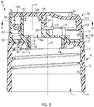
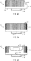
- both abutments 216 of the actuator 60 are clear of the abutment 110 of the closure body 54, such that the user may move the actuator 60 from the closed position into the open position by depressing the sloping back region 182 of the actuator 60 to cause the actuator 60 to pivot within the recesses 144 of the locking member 56.
- the two hemi-spherical projections 188 rotate within the recesses 144 of the locking member 56 such that the actuator 60 pivots about the pivot axis "P".
- the cam element 212 slides down into the locking member 56 against the wall 114 when the actuator 60 moves into the open position.
- the cam element 212 stabilizes and maintains the actuator 60 in the open position by frictional engagement with the wall 114 of the locking member 56.
- the plug 200 lifts partially out of the spout 138 so that the outlet end 194 of the dispensing flow passage 190 is exposed to the ambient environment.
- the user may then grasp the flexible, resilient container 44 to collapse or otherwise reduce the internal volume of the container 44 to pressurize the fluent substance contained therein. In some situations, the user may also invert the container 44.
- the fluent substance initially enters the inlet flow passage 74 of the closure body 54 and flows through intermediate flow passage 140 of the locking member 56, flows into the dispensing flow passage 190 of the actuator 60, and exits the closure 40 from the exposed outlet end 194.
- the outward flow of the fluent substance is stopped and may even be sucked back toward the container 44 by a temporary lower pressure within the container 44 (e.g., if the container has resilient walls that return from a "squeezed in” configuration to the normal undeformed configuration).
- a temporary lower pressure within the container 44 e.g., if the container has resilient walls that return from a "squeezed in” configuration to the normal undeformed configuration.
- the user may then move the actuator 60 from the open position into the closed position by depressing the front region 181 of the actuator 60 (which is located on the opposite side of the pivot axis "P" ( FIG. 9 ) from the sloping back region 182) to cause the two hemi-spherical projections 188 ( FIG. 9 ) to pivot within the recesses 144 ( FIG. 9 ) of the locking member 56.
- the pivoting movement of the actuator 60 causes the plug 200 to re-seal within the spout 138 and also conceals the outlet end 194 of the dispensing flow passage 190 from the ambient environment.
- the user may then grasp the locking member 56 by the outer wall 114 and twist or rotate the locking member 56 clockwise relative to the closure body 54 from the unlocking position back into the locking position.
- Rotation of the locking member 56 carries the arrow indicium 156 of the locking member 56 to the location where the arrow indicium 156 points toward the locked indicium 72 of the closure body 54.
- rotation of the locking member 56 clockwise causes the three arcuate slots 122 to move relative to the three retaining projections 94 received within them, and further causes the arcuate aperture 126 to move relative to the closure body abutment 110.
- the actuator 60 rotates through an angle of about thirty degrees about the central rotational axis "A" ( FIG. 2 ) between the unlocking position ( FIG. 9 ) and the locking position ( FIG. 6 ). With the locking member 56 oriented in the locking position, the abutment 216 of the actuator 60 overlies the abutment 110 of the closure body 54 ( FIG. 6 ).
- the user attempts to move the actuator 60 from the closed position into the open position (e.g., such as by depressing the sloping back region 182 of the actuator 60), then the user would again be prevented by contact of the abutment 216 of the actuator 60 with the abutment 110 of the closure body 54.
- FIG. 33 A second embodiment of a closure 40A according to the present invention is illustrated in FIG. 33 , and components thereof are illustrated in FIGS. 31 and 32 .
- the closure 40A includes the basic components of a base 54A, locking member 56A, and an actuator 60A.
- the second illustrated embodiment of the closure 40A operates in the same manner as discussed above with respect to the first illustrated embodiment of the closure 40, with one exception, discussed in detail below, relating to the audible and/or tactile indication of locking and/or unlocking of the closure 40A.
- the second illustrated embodiment of the closure 40A is also provided with three arcuate lugs or retaining projections 94A extending upwardly from the closure body 54A and which function to couple the closure body 54A with the locking member 56A as described above with respect to the first illustrated embodiment of the closure 40.
- One of the three retaining projections 94A has triangular projection 90A extending upwardly therefrom.
- the locking member 56A of the closure 40A is provided with a radial bridge or span 164A having a downwardly-extending tab 168A.
- the tab 168A axially-overlies a portion of the retaining projection 94A on one side of the triangular projection 90A.
- the projection 90A initially confronts and deflects the tab 168A.
Claims (12)
- Abgabeverschluss (40, 40A) für ein System (44) mit einer Öffnung (46) zwischen einem Äußeren des Systems (44) und einem Inneren des Systems (44), wo eine fließende Substanz gelagert werden kann, der Abgabeverschluss (40, 40A) umfassend:A. einen Verschlusskörper (54, 54A), der1) sich an der Systemöffnung (46) befinden kann und der einen Einlass (74) zur Kommunikation mit dem System definiert,2) ein oberes Ende (70) aufweist, das einen Durchlass (84) zur Aufnahme des Flusses einer fließenden Substanz durch den Verschlusskörper (54, 54A) definiert;B. ein Verriegelungselement (56, 56A), das auf dem Verschlusskörper (54, 54A) zur Drehung um eine zentralen Drehachse (A) angebracht ist, wobei das Verriegelungselement (56, 56A) einen Zwischenflussdurchgang (140) zur Aufnahme des Flusses einer Substanz durch den Verschlusskörperdurchlass (84) aufweist, das Verriegelungselement (56, 56A) aufweisend1) eine Verriegelungsposition und2) eine Entriegelungsposition, die um die zentrale Drehachse (A) weg von der Verriegelungsposition gedreht ist; undC. ein Betätigungselement (60, 60A), das1) drehbar an dem Verriegelungselement (56, 56A) angebracht ist, zur Verdeckung des Zwischenflussdurchgangs (140) des Verriegelungselements, um den Fluss einer fließenden Substanz durch den Verschluss (40, 40A) zu verhindern, wenn sich das Betätigungselement (60, 60A) in einer geschlossenen Nichtabgabeposition befindet, und zur Gestattung des Flusses einer fließenden Substanz durch den Verschluss (40, 40A), wenn das Betätigungselement (60, 60A) in eine offene Abgabeposition gedreht ist,2) einen Abgabeflussdurchgang (190) aufweist, der mit dem Zwischenflussdurchgang (140) des Verriegelungselements (56, 56A) in Verbindung steht, wenn sich das Betätigungselement (60, 60A) in der offenen Abgabeposition befindet, und3) mit einem Abschnitt des Verschlusskörpers (54, 54A) in Eingriff steht, wenn sich das Verriegelungselement (56, 56A) in der Verriegelungsposition befindet, um zu verhindern, dass sich das Betätigungselement (60, 60A) in die offene Abgabeposition bewegt; wobei der Abgabeverschluss ferner eine Verschlusskörperwand (71) des Verschlusskörpers (54, 54A) umfasst, die an einer oberen Decke (80) am oberen Ende (70) endet, wobei das Verriegelungselement (56, 56A) an der oberen Decke (80) des Verschlusskörpers (54, 54A) zur Drehung um eine zentrale Drehachse (A) angebracht ist, und das Verriegelungselement (56, 56A) eine Außenwand (114) aufweist, die den Zwischenflussdurchgang (140) umgibt, dadurch gekennzeichnet, dass sich die gesamte Außenwand (114) axial außerhalb der oberen Decke (80) befindet.
- Abgabeverschluss (40, 40A) nach dem vorhergehenden Anspruch, wobei der Verschlusskörper (54, 54A) zur Nutzung mit einem System (44) geeignet ist, das ein Behälter ist, der die Öffnung (46) definiert, und wobei der Verschlusskörper (54, 54A) eins von Folgendem ist: 1) eine separate Struktur zur Anbringung am Behälter (44) an der Behälteröffnung (46); und 2) eine einstückige Struktur, die ein einheitliches Teil eines Behälters (44) ist, das an der Behälteröffnung (46) ausgebildet ist.
- Abgabeverschluss (40, 40A) nach Anspruch 1, wobei die obere Decke (80) eine obere Fläche (82) definiert und das Verriegelungselement (56, 56A) eine untere Decke (118) aufweist, die eine untere Fläche (121) definiert, die der oberen Fläche (82) des Verschlusskörpers gegenüberliegt.
- Abgabeverschluss (40, 40A) nach einem der vorhergehenden Ansprüche, wobei der Durchlass (84) des Verschlusskörpers (54, 54A) eine Ausgestaltung aufweist, die auf der zentralen Drehachse (A) zentriert ist, und wenigstens ein Abschnitt des Zwischenflussdurchgangs (140) des Verriegelungselements (56, 56A) von der zentralen Drehachse (A) versetzt ist.
- Abgabeverschluss (40, 40A) nach Anspruch 1, wobei das Betätigungselement (60, 60A) mindestens einen sich abwärts erstreckenden Anschlag (216) aufweist und der Verschlusskörper (54, 54A) einen sich aufwärts erstreckenden Anschlag (110) aufweist, wobei der sich abwärts erstreckende Anschlag (216) und der sich aufwärts erstreckende Anschlag (110) orientiert sind, zu verhindern, dass sich das Betätigungselement (60, 60A) in die offene Abgabeposition bewegt, wenn sich das Verriegelungselement (56, 56A) in der Verriegelungsposition befindet, wobei vorzugsweise: 1) das Verriegelungselement (56, 56A) eine untere Decke (118) aufweist, die einen Durchlass (126) definiert, und 2) der sich aufwärts erstreckende Anschlag (110) des Verschlusskörpers (54, 54A) sich durch den Durchlass (126) erstreckt.
- Abgabeverschluss (40, 40A) nach einem der vorhergehenden Ansprüche, wobei 1) der Verschlusskörper (54, 54A) mindestens einen Haltevorsprung (94, 94A) aufweist, der sich von dem Ende (70) aufwärts erstreckt, und 2) das Verriegelungselement (56, 56A) mindestens einen bogenförmigen Schlitz (122) darin zur Aufnahme des Haltevorsprungs (94, 94A) aufweist, wobei vorzugsweise 1) der Verschlusskörper (56, 56A) eine Mehrzahl von in Umfangsrichtung beabstandeten Haltevorsprüngen (944, 94A) aufweist und 2) das Verriegelungselement (56, 56A) eine Mehrzahl von in Umfangsrichtung beabstandeten bogenförmigen Schlitzen (122) darin aufweist, wobei jeder der bogenförmigen Schlitze (122) einen anderen der Haltevorsprünge (94, 94A) aufnimmt.
- Abgabeverschluss (40A) nach einem der vorhergehenden Ansprüche, wobei1) der Verschlusskörper (54A) mindestens einen Vorsprung (90A) aufweist, der sich davon erstreckt, und2) das Verriegelungselement (56A) mindestens eine nachgiebige, biegbare Lasche (168A) aufweist, die sich davon erstreckt, wobei eine Drehung des Verriegelungselements (56A) bezogen auf den Verschlusskörper (54A) den Vorsprung (90A) gegen die Lasche (168A) und an ihr vorbei bewegt, die sich biegt und zu ihrem ungebogenen Zustand zurückkehrt, um mindestens eins von einem hörbaren Signal und einem taktilen Signal zu erzeugen.
- Abgabeverschluss (40, 40A) nach einem der vorhergehenden Ansprüche, wobei der Verschlusskörper (54, 54A) mindestens ein Anzeigeelement (72) und das Verriegelungselement (56, 56A) mindestens ein Anzeigeelement (156) aufweist, die zusammenwirken, um anzuzeigen, ob sich das Verriegelungselement (56, 56A) in einer von der Verriegelungsposition und der Entriegelungsposition befindet.
- Abgabeverschluss (40, 40A) nach einem der vorhergehenden Ansprüche, wobei das Verriegelungselement (56, 56A) weniger als 45 Grad um die zentrale Drehachse (A) zwischen der Verriegelungsposition und der Entriegelungsposition drehbar ist.
- Abgabeverschluss (40, 40A) nach einem der vorhergehenden Ansprüche, wobei 1) der Verschlusskörper (54, 54A) ferner eine sich aufwärts erstreckende Wand (86) aufweist, die den Durchlass (84) umgibt und wenigstens einen Abschnitt davon definiert, und 2) das Verriegelungselement (56, 56A) eine sich abwärts erstreckende Wand (134) aufweist, die mit der sich aufwärts erstreckenden Wand (86) des Verschlusskörpers in Dichtungseingriff steht.
- Abgabeverschluss (40, 40A) nach Anspruch 1, wobei1) das Betätigungselement (60, 60A) ein Paar Vorsprünge (188) aufweist, die sich entgegengesetzt erstrecken, und2) die Außenwand (114) des Verriegelungselements (56, 56A) ein Paar gegenüberliegender Vertiefungen (144) darin aufweist, um jeweils einen anderen der Vorsprünge (188) aufzunehmen.
- Abgabeverschluss (40, 40A) nach einem der vorhergehenden Ansprüche in Kombination mit einem System (44), der ein Behälter (44) einer fließenden Substanz ist, wobei der Verschluss (40, 40A) und der Behälter (44) zusammen eine Packung definieren.
Priority Applications (2)
| Application Number | Priority Date | Filing Date | Title |
|---|---|---|---|
| ES20188726T ES2890802T3 (es) | 2017-01-09 | 2017-01-09 | Cierre de dispensación |
| EP20188726.2A EP3747794B1 (de) | 2017-01-09 | 2017-01-09 | Ausgabeverschluss |
Applications Claiming Priority (3)
| Application Number | Priority Date | Filing Date | Title |
|---|---|---|---|
| EP20188726.2A EP3747794B1 (de) | 2017-01-09 | 2017-01-09 | Ausgabeverschluss |
| EP17889764.1A EP3565765B1 (de) | 2017-01-09 | 2017-01-09 | Ausgabeverschluss |
| PCT/US2017/012682 WO2018128627A1 (en) | 2017-01-09 | 2017-01-09 | Dispensing closure |
Related Parent Applications (2)
| Application Number | Title | Priority Date | Filing Date |
|---|---|---|---|
| EP17889764.1A Division EP3565765B1 (de) | 2017-01-09 | 2017-01-09 | Ausgabeverschluss |
| EP17889764.1A Division-Into EP3565765B1 (de) | 2017-01-09 | 2017-01-09 | Ausgabeverschluss |
Publications (2)
| Publication Number | Publication Date |
|---|---|
| EP3747794A1 EP3747794A1 (de) | 2020-12-09 |
| EP3747794B1 true EP3747794B1 (de) | 2021-07-28 |
Family
ID=62791322
Family Applications (2)
| Application Number | Title | Priority Date | Filing Date |
|---|---|---|---|
| EP20188726.2A Active EP3747794B1 (de) | 2017-01-09 | 2017-01-09 | Ausgabeverschluss |
| EP17889764.1A Active EP3565765B1 (de) | 2017-01-09 | 2017-01-09 | Ausgabeverschluss |
Family Applications After (1)
| Application Number | Title | Priority Date | Filing Date |
|---|---|---|---|
| EP17889764.1A Active EP3565765B1 (de) | 2017-01-09 | 2017-01-09 | Ausgabeverschluss |
Country Status (9)
| Country | Link |
|---|---|
| US (2) | US10266313B2 (de) |
| EP (2) | EP3747794B1 (de) |
| CN (1) | CN109890721B (de) |
| AR (1) | AR110735A1 (de) |
| BR (1) | BR112019007347A2 (de) |
| ES (2) | ES2890802T3 (de) |
| MX (1) | MX2019008080A (de) |
| RU (1) | RU2722287C1 (de) |
| WO (1) | WO2018128627A1 (de) |
Families Citing this family (7)
| Publication number | Priority date | Publication date | Assignee | Title |
|---|---|---|---|---|
| US10654623B2 (en) * | 2017-09-26 | 2020-05-19 | Can't Live Without It, LLC | Bottle with drink-through cap |
| GB201907444D0 (en) * | 2019-05-26 | 2019-07-10 | Obrist Closures Switzerland | Closure |
| US10669082B1 (en) | 2019-06-17 | 2020-06-02 | Packaging Concepts Associates Holding, Inc. | Child-resistant disk-top closure and locking system for a container |
| CN114245788A (zh) * | 2019-08-15 | 2022-03-25 | 奥布里斯特封闭瑞士有限公司 | 封闭件 |
| US20230023955A1 (en) * | 2020-01-28 | 2023-01-26 | Aptargroup, Inc. | Dispensing Closure |
| KR102376266B1 (ko) * | 2020-06-10 | 2022-03-21 | 삼화왕관주식회사 | 용기 마개 |
| US11040809B1 (en) | 2020-10-09 | 2021-06-22 | Packaging Concepts Associates Holding, Inc. | Push button tilt top closure and locking system for a container |
Family Cites Families (17)
| Publication number | Priority date | Publication date | Assignee | Title |
|---|---|---|---|---|
| US4838460A (en) * | 1987-10-09 | 1989-06-13 | Calmar Corporation | Product dispenser having actuator locking collar and shroud |
| US5279451A (en) * | 1992-03-06 | 1994-01-18 | Aptargroup, Inc. | Dispensing closure with twist collar |
| US5279926A (en) | 1992-05-06 | 1994-01-18 | International Business Machines Corporation | Method and apparatus for removing vapor from a pressurized sprayed liquid in the manufacture of semiconductor integrated circuits |
| US5284264A (en) * | 1992-09-03 | 1994-02-08 | Aptargroup, Inc. | Toggle-action dispensing closure with slide lock |
| US5314093A (en) | 1992-09-25 | 1994-05-24 | Aptargroup, Inc. | Toggle-action dispensing closure with rotatable locking ring |
| US5379926A (en) * | 1993-03-26 | 1995-01-10 | Aptargroup, Inc. | Dispensing closure with a twist sleeve and two internal passages |
| US6102225A (en) * | 1998-03-06 | 2000-08-15 | Ball Corporation | Container with internally threaded finish and seal |
| US6029866A (en) * | 1998-09-29 | 2000-02-29 | Aptargroup, Inc. | Multiple injection, toggle-action dispensing structure |
| US6065648A (en) * | 1999-06-29 | 2000-05-23 | Poly-Seal Corporation | Child resistant dispenser |
| US6283333B1 (en) * | 2001-01-17 | 2001-09-04 | Seaquist Closures Foreign, Inc. | Toggle-action dispensing closure with an actuation-prevention abutment and a recessed striker rib |
| US20020179644A1 (en) | 2002-05-30 | 2002-12-05 | Evans Christopher T. | Toggle action dispensing closure with locking means |
| US6896160B2 (en) * | 2002-12-12 | 2005-05-24 | Poly-Seal Corporation | Lockable disc top dispensing closure |
| US6971547B2 (en) * | 2003-02-05 | 2005-12-06 | Berry Plastics Corporation | Dispensing package with lockable closure |
| US6832700B2 (en) * | 2003-02-18 | 2004-12-21 | Seaquist Closures Foreign, Inc. | Toggle-action dispensing closure with an actuation-prevention system incorporating permanent deformation |
| US8322562B2 (en) * | 2008-04-30 | 2012-12-04 | Fine Line Contracting Corp. | Bellows beverage lid |
| US9555939B2 (en) * | 2015-03-04 | 2017-01-31 | Marwan Chehadeh | Bottle for upright and inverted use |
| US10167120B1 (en) * | 2018-02-20 | 2019-01-01 | Navajo Manufacturing Company, Inc. | Travel bottle with twisting locking lid |
-
2017
- 2017-01-09 EP EP20188726.2A patent/EP3747794B1/de active Active
- 2017-01-09 RU RU2019119235A patent/RU2722287C1/ru not_active IP Right Cessation
- 2017-01-09 ES ES20188726T patent/ES2890802T3/es active Active
- 2017-01-09 US US15/539,187 patent/US10266313B2/en active Active
- 2017-01-09 MX MX2019008080A patent/MX2019008080A/es unknown
- 2017-01-09 BR BR112019007347A patent/BR112019007347A2/pt not_active Application Discontinuation
- 2017-01-09 ES ES17889764T patent/ES2894266T3/es active Active
- 2017-01-09 EP EP17889764.1A patent/EP3565765B1/de active Active
- 2017-01-09 WO PCT/US2017/012682 patent/WO2018128627A1/en active Application Filing
- 2017-01-09 CN CN201780068027.6A patent/CN109890721B/zh active Active
-
2018
- 2018-01-08 AR ARP180100041A patent/AR110735A1/es active IP Right Grant
-
2019
- 2019-03-07 US US16/295,552 patent/US10518941B2/en active Active
Also Published As
| Publication number | Publication date |
|---|---|
| AR110735A1 (es) | 2019-05-02 |
| US20190202609A1 (en) | 2019-07-04 |
| US20180346210A1 (en) | 2018-12-06 |
| EP3565765A1 (de) | 2019-11-13 |
| US10518941B2 (en) | 2019-12-31 |
| ES2890802T3 (es) | 2022-01-24 |
| BR112019007347A2 (pt) | 2019-10-01 |
| EP3747794A1 (de) | 2020-12-09 |
| MX2019008080A (es) | 2019-09-06 |
| CN109890721B (zh) | 2021-11-23 |
| EP3565765A4 (de) | 2020-01-08 |
| CN109890721A (zh) | 2019-06-14 |
| US10266313B2 (en) | 2019-04-23 |
| EP3565765B1 (de) | 2021-09-01 |
| RU2722287C1 (ru) | 2020-05-28 |
| ES2894266T3 (es) | 2022-02-14 |
| WO2018128627A1 (en) | 2018-07-12 |
Similar Documents
| Publication | Publication Date | Title |
|---|---|---|
| US10518941B2 (en) | Dispensing closure | |
| US10518945B2 (en) | Closure for a container | |
| US8070014B2 (en) | Liner piercing twist closure | |
| EP3849916B1 (de) | Verschluss für einen behälter | |
| EP2181932B1 (de) | Verschluss mit drehbarem Ausgiesser zum Durchstossen einer Membran | |
| US20180029863A1 (en) | Liquid dispenser | |
| US11524821B2 (en) | Dispensing closure for a container | |
| EP3003894A1 (de) | Verschluss mit einem deckel und entfernbarer membran | |
| US11352178B2 (en) | Closure for a container | |
| EP4051600B1 (de) | Ausgabeverschluss | |
| US20200140152A1 (en) | Closure for a container | |
| US11858699B2 (en) | Dispensing closure for a container | |
| US20230091031A1 (en) | Dispensing System | |
| WO2015094234A1 (en) | Dispensing closure | |
| WO2023014627A1 (en) | Dispensing closure | |
| WO2023244556A1 (en) | Closure, container and assembly thereof |
Legal Events
| Date | Code | Title | Description |
|---|---|---|---|
| PUAI | Public reference made under article 153(3) epc to a published international application that has entered the european phase |
Free format text: ORIGINAL CODE: 0009012 |
|
| STAA | Information on the status of an ep patent application or granted ep patent |
Free format text: STATUS: THE APPLICATION HAS BEEN PUBLISHED |
|
| AC | Divisional application: reference to earlier application |
Ref document number: 3565765 Country of ref document: EP Kind code of ref document: P |
|
| AK | Designated contracting states |
Kind code of ref document: A1 Designated state(s): AL AT BE BG CH CY CZ DE DK EE ES FI FR GB GR HR HU IE IS IT LI LT LU LV MC MK MT NL NO PL PT RO RS SE SI SK SM TR |
|
| STAA | Information on the status of an ep patent application or granted ep patent |
Free format text: STATUS: REQUEST FOR EXAMINATION WAS MADE |
|
| 17P | Request for examination filed |
Effective date: 20201214 |
|
| RBV | Designated contracting states (corrected) |
Designated state(s): AL AT BE BG CH CY CZ DE DK EE ES FI FR GB GR HR HU IE IS IT LI LT LU LV MC MK MT NL NO PL PT RO RS SE SI SK SM TR |
|
| GRAP | Despatch of communication of intention to grant a patent |
Free format text: ORIGINAL CODE: EPIDOSNIGR1 |
|
| STAA | Information on the status of an ep patent application or granted ep patent |
Free format text: STATUS: GRANT OF PATENT IS INTENDED |
|
| INTG | Intention to grant announced |
Effective date: 20210223 |
|
| GRAS | Grant fee paid |
Free format text: ORIGINAL CODE: EPIDOSNIGR3 |
|
| GRAA | (expected) grant |
Free format text: ORIGINAL CODE: 0009210 |
|
| STAA | Information on the status of an ep patent application or granted ep patent |
Free format text: STATUS: THE PATENT HAS BEEN GRANTED |
|
| AC | Divisional application: reference to earlier application |
Ref document number: 3565765 Country of ref document: EP Kind code of ref document: P |
|
| AK | Designated contracting states |
Kind code of ref document: B1 Designated state(s): AL AT BE BG CH CY CZ DE DK EE ES FI FR GB GR HR HU IE IS IT LI LT LU LV MC MK MT NL NO PL PT RO RS SE SI SK SM TR |
|
| REG | Reference to a national code |
Ref country code: GB Ref legal event code: FG4D |
|
| REG | Reference to a national code |
Ref country code: CH Ref legal event code: EP |
|
| REG | Reference to a national code |
Ref country code: AT Ref legal event code: REF Ref document number: 1414564 Country of ref document: AT Kind code of ref document: T Effective date: 20210815 |
|
| REG | Reference to a national code |
Ref country code: IE Ref legal event code: FG4D |
|
| REG | Reference to a national code |
Ref country code: DE Ref legal event code: R096 Ref document number: 602017043188 Country of ref document: DE |
|
| REG | Reference to a national code |
Ref country code: LT Ref legal event code: MG9D |
|
| REG | Reference to a national code |
Ref country code: NL Ref legal event code: MP Effective date: 20210728 |
|
| REG | Reference to a national code |
Ref country code: AT Ref legal event code: MK05 Ref document number: 1414564 Country of ref document: AT Kind code of ref document: T Effective date: 20210728 |
|
| REG | Reference to a national code |
Ref country code: ES Ref legal event code: FG2A Ref document number: 2890802 Country of ref document: ES Kind code of ref document: T3 Effective date: 20220124 |
|
| PG25 | Lapsed in a contracting state [announced via postgrant information from national office to epo] |
Ref country code: PT Free format text: LAPSE BECAUSE OF FAILURE TO SUBMIT A TRANSLATION OF THE DESCRIPTION OR TO PAY THE FEE WITHIN THE PRESCRIBED TIME-LIMIT Effective date: 20211129 Ref country code: NL Free format text: LAPSE BECAUSE OF FAILURE TO SUBMIT A TRANSLATION OF THE DESCRIPTION OR TO PAY THE FEE WITHIN THE PRESCRIBED TIME-LIMIT Effective date: 20210728 Ref country code: NO Free format text: LAPSE BECAUSE OF FAILURE TO SUBMIT A TRANSLATION OF THE DESCRIPTION OR TO PAY THE FEE WITHIN THE PRESCRIBED TIME-LIMIT Effective date: 20211028 Ref country code: FI Free format text: LAPSE BECAUSE OF FAILURE TO SUBMIT A TRANSLATION OF THE DESCRIPTION OR TO PAY THE FEE WITHIN THE PRESCRIBED TIME-LIMIT Effective date: 20210728 Ref country code: HR Free format text: LAPSE BECAUSE OF FAILURE TO SUBMIT A TRANSLATION OF THE DESCRIPTION OR TO PAY THE FEE WITHIN THE PRESCRIBED TIME-LIMIT Effective date: 20210728 Ref country code: LT Free format text: LAPSE BECAUSE OF FAILURE TO SUBMIT A TRANSLATION OF THE DESCRIPTION OR TO PAY THE FEE WITHIN THE PRESCRIBED TIME-LIMIT Effective date: 20210728 Ref country code: BG Free format text: LAPSE BECAUSE OF FAILURE TO SUBMIT A TRANSLATION OF THE DESCRIPTION OR TO PAY THE FEE WITHIN THE PRESCRIBED TIME-LIMIT Effective date: 20211028 Ref country code: AT Free format text: LAPSE BECAUSE OF FAILURE TO SUBMIT A TRANSLATION OF THE DESCRIPTION OR TO PAY THE FEE WITHIN THE PRESCRIBED TIME-LIMIT Effective date: 20210728 Ref country code: RS Free format text: LAPSE BECAUSE OF FAILURE TO SUBMIT A TRANSLATION OF THE DESCRIPTION OR TO PAY THE FEE WITHIN THE PRESCRIBED TIME-LIMIT Effective date: 20210728 Ref country code: SE Free format text: LAPSE BECAUSE OF FAILURE TO SUBMIT A TRANSLATION OF THE DESCRIPTION OR TO PAY THE FEE WITHIN THE PRESCRIBED TIME-LIMIT Effective date: 20210728 |
|
| PG25 | Lapsed in a contracting state [announced via postgrant information from national office to epo] |
Ref country code: PL Free format text: LAPSE BECAUSE OF FAILURE TO SUBMIT A TRANSLATION OF THE DESCRIPTION OR TO PAY THE FEE WITHIN THE PRESCRIBED TIME-LIMIT Effective date: 20210728 Ref country code: LV Free format text: LAPSE BECAUSE OF FAILURE TO SUBMIT A TRANSLATION OF THE DESCRIPTION OR TO PAY THE FEE WITHIN THE PRESCRIBED TIME-LIMIT Effective date: 20210728 Ref country code: GR Free format text: LAPSE BECAUSE OF FAILURE TO SUBMIT A TRANSLATION OF THE DESCRIPTION OR TO PAY THE FEE WITHIN THE PRESCRIBED TIME-LIMIT Effective date: 20211029 |
|
| PG25 | Lapsed in a contracting state [announced via postgrant information from national office to epo] |
Ref country code: DK Free format text: LAPSE BECAUSE OF FAILURE TO SUBMIT A TRANSLATION OF THE DESCRIPTION OR TO PAY THE FEE WITHIN THE PRESCRIBED TIME-LIMIT Effective date: 20210728 |
|
| REG | Reference to a national code |
Ref country code: DE Ref legal event code: R097 Ref document number: 602017043188 Country of ref document: DE |
|
| PG25 | Lapsed in a contracting state [announced via postgrant information from national office to epo] |
Ref country code: SM Free format text: LAPSE BECAUSE OF FAILURE TO SUBMIT A TRANSLATION OF THE DESCRIPTION OR TO PAY THE FEE WITHIN THE PRESCRIBED TIME-LIMIT Effective date: 20210728 Ref country code: SK Free format text: LAPSE BECAUSE OF FAILURE TO SUBMIT A TRANSLATION OF THE DESCRIPTION OR TO PAY THE FEE WITHIN THE PRESCRIBED TIME-LIMIT Effective date: 20210728 Ref country code: RO Free format text: LAPSE BECAUSE OF FAILURE TO SUBMIT A TRANSLATION OF THE DESCRIPTION OR TO PAY THE FEE WITHIN THE PRESCRIBED TIME-LIMIT Effective date: 20210728 Ref country code: EE Free format text: LAPSE BECAUSE OF FAILURE TO SUBMIT A TRANSLATION OF THE DESCRIPTION OR TO PAY THE FEE WITHIN THE PRESCRIBED TIME-LIMIT Effective date: 20210728 Ref country code: CZ Free format text: LAPSE BECAUSE OF FAILURE TO SUBMIT A TRANSLATION OF THE DESCRIPTION OR TO PAY THE FEE WITHIN THE PRESCRIBED TIME-LIMIT Effective date: 20210728 Ref country code: AL Free format text: LAPSE BECAUSE OF FAILURE TO SUBMIT A TRANSLATION OF THE DESCRIPTION OR TO PAY THE FEE WITHIN THE PRESCRIBED TIME-LIMIT Effective date: 20210728 |
|
| PLBE | No opposition filed within time limit |
Free format text: ORIGINAL CODE: 0009261 |
|
| STAA | Information on the status of an ep patent application or granted ep patent |
Free format text: STATUS: NO OPPOSITION FILED WITHIN TIME LIMIT |
|
| 26N | No opposition filed |
Effective date: 20220429 |
|
| PG25 | Lapsed in a contracting state [announced via postgrant information from national office to epo] |
Ref country code: MC Free format text: LAPSE BECAUSE OF FAILURE TO SUBMIT A TRANSLATION OF THE DESCRIPTION OR TO PAY THE FEE WITHIN THE PRESCRIBED TIME-LIMIT Effective date: 20210728 |
|
| REG | Reference to a national code |
Ref country code: CH Ref legal event code: PL |
|
| REG | Reference to a national code |
Ref country code: BE Ref legal event code: MM Effective date: 20220131 |
|
| PG25 | Lapsed in a contracting state [announced via postgrant information from national office to epo] |
Ref country code: LU Free format text: LAPSE BECAUSE OF NON-PAYMENT OF DUE FEES Effective date: 20220109 |
|
| PG25 | Lapsed in a contracting state [announced via postgrant information from national office to epo] |
Ref country code: BE Free format text: LAPSE BECAUSE OF NON-PAYMENT OF DUE FEES Effective date: 20220131 |
|
| PG25 | Lapsed in a contracting state [announced via postgrant information from national office to epo] |
Ref country code: LI Free format text: LAPSE BECAUSE OF NON-PAYMENT OF DUE FEES Effective date: 20220131 Ref country code: CH Free format text: LAPSE BECAUSE OF NON-PAYMENT OF DUE FEES Effective date: 20220131 |
|
| PG25 | Lapsed in a contracting state [announced via postgrant information from national office to epo] |
Ref country code: IE Free format text: LAPSE BECAUSE OF NON-PAYMENT OF DUE FEES Effective date: 20220109 |
|
| PGFP | Annual fee paid to national office [announced via postgrant information from national office to epo] |
Ref country code: FR Payment date: 20230125 Year of fee payment: 7 Ref country code: ES Payment date: 20230201 Year of fee payment: 7 |
|
| PGFP | Annual fee paid to national office [announced via postgrant information from national office to epo] |
Ref country code: IT Payment date: 20230120 Year of fee payment: 7 Ref country code: GB Payment date: 20230127 Year of fee payment: 7 Ref country code: DE Payment date: 20230127 Year of fee payment: 7 |
|
| P01 | Opt-out of the competence of the unified patent court (upc) registered |
Effective date: 20230509 |
|
| PGFP | Annual fee paid to national office [announced via postgrant information from national office to epo] |
Ref country code: ES Payment date: 20240201 Year of fee payment: 8 |