EP3747529A1 - Gas treatment device - Google Patents
Gas treatment device Download PDFInfo
- Publication number
- EP3747529A1 EP3747529A1 EP20175333.2A EP20175333A EP3747529A1 EP 3747529 A1 EP3747529 A1 EP 3747529A1 EP 20175333 A EP20175333 A EP 20175333A EP 3747529 A1 EP3747529 A1 EP 3747529A1
- Authority
- EP
- European Patent Office
- Prior art keywords
- gas
- treated
- filter
- substance
- treatment device
- Prior art date
- Legal status (The legal status is an assumption and is not a legal conclusion. Google has not performed a legal analysis and makes no representation as to the accuracy of the status listed.)
- Pending
Links
- 239000000126 substance Substances 0.000 claims abstract description 88
- 239000012855 volatile organic compound Substances 0.000 claims abstract description 56
- 239000000443 aerosol Substances 0.000 claims abstract description 11
- 230000015572 biosynthetic process Effects 0.000 claims abstract description 9
- 239000000203 mixture Substances 0.000 claims abstract description 5
- 230000001678 irradiating effect Effects 0.000 claims abstract description 4
- CBENFWSGALASAD-UHFFFAOYSA-N Ozone Chemical compound [O-][O+]=O CBENFWSGALASAD-UHFFFAOYSA-N 0.000 claims description 48
- KFZMGEQAYNKOFK-UHFFFAOYSA-N Isopropanol Chemical compound CC(C)O KFZMGEQAYNKOFK-UHFFFAOYSA-N 0.000 claims description 15
- OKKJLVBELUTLKV-UHFFFAOYSA-N Methanol Chemical compound OC OKKJLVBELUTLKV-UHFFFAOYSA-N 0.000 claims description 15
- YXFVVABEGXRONW-UHFFFAOYSA-N Toluene Chemical compound CC1=CC=CC=C1 YXFVVABEGXRONW-UHFFFAOYSA-N 0.000 claims description 15
- CTQNGGLPUBDAKN-UHFFFAOYSA-N O-Xylene Chemical compound CC1=CC=CC=C1C CTQNGGLPUBDAKN-UHFFFAOYSA-N 0.000 claims description 14
- 239000008096 xylene Substances 0.000 claims description 14
- CSCPPACGZOOCGX-UHFFFAOYSA-N Acetone Chemical compound CC(C)=O CSCPPACGZOOCGX-UHFFFAOYSA-N 0.000 claims description 11
- 239000000428 dust Substances 0.000 claims description 11
- ZWEHNKRNPOVVGH-UHFFFAOYSA-N 2-Butanone Chemical compound CCC(C)=O ZWEHNKRNPOVVGH-UHFFFAOYSA-N 0.000 claims description 9
- HEDRZPFGACZZDS-UHFFFAOYSA-N Chloroform Chemical compound ClC(Cl)Cl HEDRZPFGACZZDS-UHFFFAOYSA-N 0.000 claims description 6
- YNQLUTRBYVCPMQ-UHFFFAOYSA-N Ethylbenzene Chemical compound CCC1=CC=CC=C1 YNQLUTRBYVCPMQ-UHFFFAOYSA-N 0.000 claims description 6
- PPBRXRYQALVLMV-UHFFFAOYSA-N Styrene Chemical compound C=CC1=CC=CC=C1 PPBRXRYQALVLMV-UHFFFAOYSA-N 0.000 claims description 6
- VZGDMQKNWNREIO-UHFFFAOYSA-N tetrachloromethane Chemical compound ClC(Cl)(Cl)Cl VZGDMQKNWNREIO-UHFFFAOYSA-N 0.000 claims description 6
- IAYPIBMASNFSPL-UHFFFAOYSA-N Ethylene oxide Chemical compound C1CO1 IAYPIBMASNFSPL-UHFFFAOYSA-N 0.000 claims description 4
- WSFSSNUMVMOOMR-NJFSPNSNSA-N methanone Chemical compound O=[14CH2] WSFSSNUMVMOOMR-NJFSPNSNSA-N 0.000 claims description 4
- NTIZESTWPVYFNL-UHFFFAOYSA-N Methyl isobutyl ketone Chemical compound CC(C)CC(C)=O NTIZESTWPVYFNL-UHFFFAOYSA-N 0.000 claims description 3
- UIHCLUNTQKBZGK-UHFFFAOYSA-N Methyl isobutyl ketone Natural products CCC(C)C(C)=O UIHCLUNTQKBZGK-UHFFFAOYSA-N 0.000 claims description 3
- 150000001298 alcohols Chemical class 0.000 claims description 3
- 150000001299 aldehydes Chemical class 0.000 claims description 3
- 150000001348 alkyl chlorides Chemical class 0.000 claims description 3
- 150000002576 ketones Chemical class 0.000 claims description 3
- 125000001997 phenyl group Chemical group [H]C1=C([H])C([H])=C(*)C([H])=C1[H] 0.000 claims description 3
- 150000002924 oxiranes Chemical class 0.000 claims description 2
- 239000007789 gas Substances 0.000 description 185
- WSFSSNUMVMOOMR-UHFFFAOYSA-N Formaldehyde Chemical compound O=C WSFSSNUMVMOOMR-UHFFFAOYSA-N 0.000 description 34
- QVGXLLKOCUKJST-UHFFFAOYSA-N atomic oxygen Chemical compound [O] QVGXLLKOCUKJST-UHFFFAOYSA-N 0.000 description 12
- 238000006243 chemical reaction Methods 0.000 description 12
- 230000000052 comparative effect Effects 0.000 description 8
- NUJOXMJBOLGQSY-UHFFFAOYSA-N manganese dioxide Chemical compound O=[Mn]=O NUJOXMJBOLGQSY-UHFFFAOYSA-N 0.000 description 8
- 239000002245 particle Substances 0.000 description 7
- 238000011144 upstream manufacturing Methods 0.000 description 7
- XEKOWRVHYACXOJ-UHFFFAOYSA-N Ethyl acetate Chemical compound CCOC(C)=O XEKOWRVHYACXOJ-UHFFFAOYSA-N 0.000 description 6
- KDLHZDBZIXYQEI-UHFFFAOYSA-N Palladium Chemical compound [Pd] KDLHZDBZIXYQEI-UHFFFAOYSA-N 0.000 description 6
- 239000003054 catalyst Substances 0.000 description 6
- BASFCYQUMIYNBI-UHFFFAOYSA-N platinum Chemical compound [Pt] BASFCYQUMIYNBI-UHFFFAOYSA-N 0.000 description 6
- 238000000354 decomposition reaction Methods 0.000 description 5
- 230000007423 decrease Effects 0.000 description 5
- -1 for example Substances 0.000 description 5
- 238000000034 method Methods 0.000 description 5
- 239000001301 oxygen Substances 0.000 description 5
- 229910052760 oxygen Inorganic materials 0.000 description 5
- 125000004430 oxygen atom Chemical group O* 0.000 description 5
- OKTJSMMVPCPJKN-UHFFFAOYSA-N Carbon Chemical compound [C] OKTJSMMVPCPJKN-UHFFFAOYSA-N 0.000 description 4
- UQSXHKLRYXJYBZ-UHFFFAOYSA-N Iron oxide Chemical compound [Fe]=O UQSXHKLRYXJYBZ-UHFFFAOYSA-N 0.000 description 4
- 239000000835 fiber Substances 0.000 description 4
- 229910052751 metal Inorganic materials 0.000 description 4
- 239000002184 metal Substances 0.000 description 4
- 229910000480 nickel oxide Inorganic materials 0.000 description 4
- 239000010948 rhodium Substances 0.000 description 4
- 239000011163 secondary particle Substances 0.000 description 4
- 238000001179 sorption measurement Methods 0.000 description 4
- VYPSYNLAJGMNEJ-UHFFFAOYSA-N Silicium dioxide Chemical compound O=[Si]=O VYPSYNLAJGMNEJ-UHFFFAOYSA-N 0.000 description 3
- 229910052724 xenon Inorganic materials 0.000 description 3
- FHNFHKCVQCLJFQ-UHFFFAOYSA-N xenon atom Chemical compound [Xe] FHNFHKCVQCLJFQ-UHFFFAOYSA-N 0.000 description 3
- KRHYYFGTRYWZRS-UHFFFAOYSA-M Fluoride anion Chemical compound [F-] KRHYYFGTRYWZRS-UHFFFAOYSA-M 0.000 description 2
- 229910021536 Zeolite Inorganic materials 0.000 description 2
- 239000003463 adsorbent Substances 0.000 description 2
- 229910052782 aluminium Inorganic materials 0.000 description 2
- XAGFODPZIPBFFR-UHFFFAOYSA-N aluminium Chemical compound [Al] XAGFODPZIPBFFR-UHFFFAOYSA-N 0.000 description 2
- 230000033228 biological regulation Effects 0.000 description 2
- 239000000919 ceramic Substances 0.000 description 2
- HNPSIPDUKPIQMN-UHFFFAOYSA-N dioxosilane;oxo(oxoalumanyloxy)alumane Chemical compound O=[Si]=O.O=[Al]O[Al]=O HNPSIPDUKPIQMN-UHFFFAOYSA-N 0.000 description 2
- 239000003814 drug Substances 0.000 description 2
- 238000001914 filtration Methods 0.000 description 2
- 239000008098 formaldehyde solution Substances 0.000 description 2
- 239000003365 glass fiber Substances 0.000 description 2
- 230000005283 ground state Effects 0.000 description 2
- JEIPFZHSYJVQDO-UHFFFAOYSA-N iron(III) oxide Inorganic materials O=[Fe]O[Fe]=O JEIPFZHSYJVQDO-UHFFFAOYSA-N 0.000 description 2
- 229910044991 metal oxide Inorganic materials 0.000 description 2
- 150000004706 metal oxides Chemical class 0.000 description 2
- 239000004745 nonwoven fabric Substances 0.000 description 2
- GNRSAWUEBMWBQH-UHFFFAOYSA-N oxonickel Chemical compound [Ni]=O GNRSAWUEBMWBQH-UHFFFAOYSA-N 0.000 description 2
- 229910052763 palladium Inorganic materials 0.000 description 2
- 229910052697 platinum Inorganic materials 0.000 description 2
- 229920000728 polyester Polymers 0.000 description 2
- 229910052703 rhodium Inorganic materials 0.000 description 2
- MHOVAHRLVXNVSD-UHFFFAOYSA-N rhodium atom Chemical compound [Rh] MHOVAHRLVXNVSD-UHFFFAOYSA-N 0.000 description 2
- 239000000741 silica gel Substances 0.000 description 2
- 229910002027 silica gel Inorganic materials 0.000 description 2
- 229910001220 stainless steel Inorganic materials 0.000 description 2
- 239000010935 stainless steel Substances 0.000 description 2
- 239000010457 zeolite Substances 0.000 description 2
- UFHFLCQGNIYNRP-UHFFFAOYSA-N Hydrogen Chemical compound [H][H] UFHFLCQGNIYNRP-UHFFFAOYSA-N 0.000 description 1
- PNEYBMLMFCGWSK-UHFFFAOYSA-N aluminium oxide Inorganic materials [O-2].[O-2].[O-2].[Al+3].[Al+3] PNEYBMLMFCGWSK-UHFFFAOYSA-N 0.000 description 1
- 125000004429 atom Chemical group 0.000 description 1
- 229910010293 ceramic material Inorganic materials 0.000 description 1
- 239000000356 contaminant Substances 0.000 description 1
- 239000003989 dielectric material Substances 0.000 description 1
- 230000000694 effects Effects 0.000 description 1
- 230000007613 environmental effect Effects 0.000 description 1
- 230000005281 excited state Effects 0.000 description 1
- 229910052839 forsterite Inorganic materials 0.000 description 1
- 231100001261 hazardous Toxicity 0.000 description 1
- 239000001257 hydrogen Substances 0.000 description 1
- 229910052739 hydrogen Inorganic materials 0.000 description 1
- 229910010272 inorganic material Inorganic materials 0.000 description 1
- 239000011147 inorganic material Substances 0.000 description 1
- 230000031700 light absorption Effects 0.000 description 1
- HCWCAKKEBCNQJP-UHFFFAOYSA-N magnesium orthosilicate Chemical compound [Mg+2].[Mg+2].[O-][Si]([O-])([O-])[O-] HCWCAKKEBCNQJP-UHFFFAOYSA-N 0.000 description 1
- 229910052754 neon Inorganic materials 0.000 description 1
- GKAOGPIIYCISHV-UHFFFAOYSA-N neon atom Chemical compound [Ne] GKAOGPIIYCISHV-UHFFFAOYSA-N 0.000 description 1
- 150000002894 organic compounds Chemical class 0.000 description 1
- 230000005855 radiation Effects 0.000 description 1
- 238000010200 validation analysis Methods 0.000 description 1
Images




Classifications
-
- B—PERFORMING OPERATIONS; TRANSPORTING
- B01—PHYSICAL OR CHEMICAL PROCESSES OR APPARATUS IN GENERAL
- B01D—SEPARATION
- B01D53/00—Separation of gases or vapours; Recovering vapours of volatile solvents from gases; Chemical or biological purification of waste gases, e.g. engine exhaust gases, smoke, fumes, flue gases, aerosols
- B01D53/02—Separation of gases or vapours; Recovering vapours of volatile solvents from gases; Chemical or biological purification of waste gases, e.g. engine exhaust gases, smoke, fumes, flue gases, aerosols by adsorption, e.g. preparative gas chromatography
- B01D53/04—Separation of gases or vapours; Recovering vapours of volatile solvents from gases; Chemical or biological purification of waste gases, e.g. engine exhaust gases, smoke, fumes, flue gases, aerosols by adsorption, e.g. preparative gas chromatography with stationary adsorbents
- B01D53/0407—Constructional details of adsorbing systems
-
- B—PERFORMING OPERATIONS; TRANSPORTING
- B01—PHYSICAL OR CHEMICAL PROCESSES OR APPARATUS IN GENERAL
- B01D—SEPARATION
- B01D53/00—Separation of gases or vapours; Recovering vapours of volatile solvents from gases; Chemical or biological purification of waste gases, e.g. engine exhaust gases, smoke, fumes, flue gases, aerosols
- B01D53/02—Separation of gases or vapours; Recovering vapours of volatile solvents from gases; Chemical or biological purification of waste gases, e.g. engine exhaust gases, smoke, fumes, flue gases, aerosols by adsorption, e.g. preparative gas chromatography
- B01D53/04—Separation of gases or vapours; Recovering vapours of volatile solvents from gases; Chemical or biological purification of waste gases, e.g. engine exhaust gases, smoke, fumes, flue gases, aerosols by adsorption, e.g. preparative gas chromatography with stationary adsorbents
-
- B—PERFORMING OPERATIONS; TRANSPORTING
- B01—PHYSICAL OR CHEMICAL PROCESSES OR APPARATUS IN GENERAL
- B01D—SEPARATION
- B01D2251/00—Reactants
- B01D2251/10—Oxidants
- B01D2251/104—Ozone
-
- B—PERFORMING OPERATIONS; TRANSPORTING
- B01—PHYSICAL OR CHEMICAL PROCESSES OR APPARATUS IN GENERAL
- B01D—SEPARATION
- B01D2253/00—Adsorbents used in seperation treatment of gases and vapours
- B01D2253/10—Inorganic adsorbents
- B01D2253/106—Silica or silicates
- B01D2253/108—Zeolites
-
- B—PERFORMING OPERATIONS; TRANSPORTING
- B01—PHYSICAL OR CHEMICAL PROCESSES OR APPARATUS IN GENERAL
- B01D—SEPARATION
- B01D2255/00—Catalysts
- B01D2255/10—Noble metals or compounds thereof
- B01D2255/102—Platinum group metals
-
- B—PERFORMING OPERATIONS; TRANSPORTING
- B01—PHYSICAL OR CHEMICAL PROCESSES OR APPARATUS IN GENERAL
- B01D—SEPARATION
- B01D2255/00—Catalysts
- B01D2255/90—Physical characteristics of catalysts
- B01D2255/915—Catalyst supported on particulate filters
-
- B—PERFORMING OPERATIONS; TRANSPORTING
- B01—PHYSICAL OR CHEMICAL PROCESSES OR APPARATUS IN GENERAL
- B01D—SEPARATION
- B01D2257/00—Components to be removed
- B01D2257/70—Organic compounds not provided for in groups B01D2257/00 - B01D2257/602
- B01D2257/708—Volatile organic compounds V.O.C.'s
-
- B—PERFORMING OPERATIONS; TRANSPORTING
- B01—PHYSICAL OR CHEMICAL PROCESSES OR APPARATUS IN GENERAL
- B01D—SEPARATION
- B01D2258/00—Sources of waste gases
- B01D2258/06—Polluted air
-
- B—PERFORMING OPERATIONS; TRANSPORTING
- B01—PHYSICAL OR CHEMICAL PROCESSES OR APPARATUS IN GENERAL
- B01D—SEPARATION
- B01D2259/00—Type of treatment
- B01D2259/80—Employing electric, magnetic, electromagnetic or wave energy, or particle radiation
- B01D2259/804—UV light
Definitions
- the present invention relates to a gas treatment device, and more particularly to a gas treatment device for treating a gas to be treated containing VOCs (Volatile Organic Compounds).
- VOCs Volatile Organic Compounds
- Patent Document 1 specified below discloses a gas treatment device that treats a gas to be treated by irradiating air containing VOCs with ultraviolet.
- Fig. 11 is a drawing illustrating a schematic configuration of the gas treatment device disclosed in Patent Document 1.
- the gas treatment device 100 includes a flow path 101 for VOC-containing air G100 that is the object of treatment to flow through, an ultraviolet light source 102 disposed inside the flow path, a particulate filter 103, and an ozone-decomposing filter 104.
- Patent Document 1 mentions toluene, xylene, and ethyl acetate as examples of VOCs.
- Patent Document 1 JP-A-2018-89106
- Substances that belong to VOCs include types that hardly form particles when irradiated with ultraviolet and that can hardly be broken down even by ozone, such as formaldehyde. If the air to be treated G100 contains formaldehyde, for example, the gas treatment device 100 described in Patent Document 1 is not able to remove formaldehyde sufficiently. The gas treatment device 100 therefore will exhaust the treated air G101, from which formaldehyde is not fully removed, which is undesirable.
- the inventor investigated a method of decomposing formaldehyde using the gas treatment device 100 illustrated in Fig. 11 , wherein a xenon excimer lamp was used as the ultraviolet light source 102 to irradiate the air to be treated G100 with ultraviolet L102 having shorter wavelengths so that hydroxyl radicals ( ⁇ OH) that are more reactive than ozone are generated to be used for decomposition of formaldehyde.
- ⁇ OH hydroxyl radicals
- this method entailed the problem of contaminants deposited on the wall of the arc tube (tube body) of the excimer lamp, which is used as the ultraviolet light source 102, as the treatment of the air G100 progresses, resulting in lowered illuminance of the ultraviolet L102. This phenomenon lowers the radical formation potential and compromises the VOC decomposition capability, which is not preferable.
- an object of the present invention is to realize a gas treatment device that performs a treatment to a flowing gas to be treated, which is air containing a VOC, the device being capable of treating even a gas containing a substance that is hardly decomposed by ozone, and capable of keeping treatment capacity over time.
- the present invention provides a gas treatment device performing a treatment to a gas to be treated that is a mixture of air and a VOC flowing through a treatment chamber.
- the device includes:
- the first substance has a higher adsorbability to the first filter in a gaseous form and a higher aerosol formation potential when irradiated with the ultraviolet than the second substance.
- Aerosol formation potential herein is defined as the yield of secondary organic aerosols (SOAs) per unit amount of consumed VOC, and used as the index of how readily SOA is generated for each substance that forms a VOC. More specifically, the yield is defined by the value Y as expressed by the following Formula (1).
- Mo represents the aerosol concentration [ ⁇ g/m 3 ]
- ⁇ VOC represents the amount of VOC [ppb] consumed in the (photochemical) reaction.
- Y M 0 / ⁇ VOC
- a first filter is disposed closer to the intake port than the excimer lamp, i.e., upstream, inside the treatment chamber. Therefore, when a gas that is air containing a first substance and a second substance that belong to VOCs is introduced from the intake port into the treatment chamber as the gas to be treated, this gas passes through the first filter before irradiated with ultraviolet from the excimer lamp. As a result, the first substance contained in the gas to be treated is adsorbed by the first filter, and the gas to be treated with a much reduced concentration of the first substance is irradiated with the ultraviolet from the excimer lamp.
- the first substance is a substance that shows a high aerosol formation potential when irradiated with ultraviolet, by the time the gas to be treated passes near the excimer lamp, the first substance has already been removed, so that adhesion of aerosol particles originating from the first substance on the tube body of the excimer lamp is inhibited.
- the gas to be treated after having passed through the first filter still contains the second substance therein.
- this gas to be treated is irradiated with the ultraviolet from the excimer lamp, so that the second substance is decomposed by radicals generated when the oxygen contained in the gas to be treated is decomposed.
- the concentrations of both the first substance and the second substance can be reduced before the air is exhausted from the exhaust port.
- the first filter is configured as a gas adsorption filter that includes a porous adsorbent such as, for example, activated carbon, zeolite, silica gel, and so on.
- a porous adsorbent such as, for example, activated carbon, zeolite, silica gel, and so on.
- the first substance may either contain a phenyl group or belong to alkyl chlorides, and the second substance may belong to any one of alcohols, ketones, aldehydes, and epoxides.
- the first substance may be one or more of substances included in the group consisting of toluene, xylene, styrene, ethyl benzene, chloroform, and carbon tetrachloride
- the second substance may be one or more of substances included in the group consisting of formaldehyde, ethylene oxide, methanol, isopropyl alcohol, acetone, methyl ethyl ketone, and methyl isobutyl ketone.
- the excimer lamp may include an arc tube hermetically filled with a discharge gas containing Xe and arranged longitudinally along a direction in which the gas to be treated flows.
- the excimer lamp emits ultraviolet having a peak wavelength of 160 nm or more and less than 200 nm to irradiate the gas to be treated.
- This enhances the formation efficiency of hydroxyl radicals ( ⁇ OH) that are particularly reactive, and this way, a gas treatment device with excellent capability to decompose the second substance is realized.
- the excimer lamp is disposed inside the treatment chamber such that the arc tube in the excimer lamp extends longitudinally along the direction in which the gas to be treated flows, so that the gas to be treated flowing through the treatment chamber can be irradiated with ultraviolet over a length of time required for the gas to be treated to move a distance corresponding to the length of the tube body (more particularly, emission length). This allows the gas to be treated to be irradiated with a sufficient amount of ultraviolet so that a high concentration of radicals including hydroxyl radicals ( ⁇ OH) are generated to contribute to decomposition of the second substance.
- the gas treatment device may further include a second filter disposed closer to the exhaust port than the excimer lamp inside the treatment chamber and capable of decomposing ozone.
- Irradiation of the gas to be treated with the ultraviolet from the excimer lamp produces radicals such as hydroxyl radicals ( ⁇ OH) as well as ozone (O 3 ).
- This ozone is less reactive than radicals and may be left in the gas to be treated and discharged from the exhaust port. Since ozone is a substance hazardous to the human body, it is preferable to reduce the concentration of ozone emission to the outside of the gas treatment device.
- a second filter is disposed closer to the exhaust port than the excimer lamp, i.e., downstream of the excimer lamp. Therefore, the ozone generated when the gas to be treated is irradiated with ultraviolet from the excimer lamp is decomposed by the second filter, so that the air discharged from the exhaust port contains a low concentration of ozone, as well as a low concentration of VOCs.
- a catalyst for the second filter, structures wherein a catalyst is carried on a base member having a honeycomb structure made of metal such as aluminum and stainless steel, or ceramics, may be employed.
- rare metal catalysts such as palladium (Pd), rhodium (Rh), platinum (Pt) and the like, or metal oxides such as manganese dioxide (MnO 2 ), iron (II) oxide (Fe 2 O 3 ), nickel oxide (NiO) and the like may be used.
- the gas treatment device may further include an ozone-resistant third filter disposed closer to the intake port than the first filter inside the treatment chamber and capable of adsorbing dust contained in the gas to be treated.
- a medium efficiency particulate air filter means a filter that has a medium level particulate filtration efficiency to particulates primarily of a particle size of 0.5 pm or more and less than 5 pm, i.e., a filter having a filtration efficiency of 50% to less than 95% as measured by a dust spot method (JIS B 9908).
- the gas treatment device may further include a circulation flow path that introduces at least part of the gas to be treated that has passed through the second filter to a point between the third filter and the intake port.
- the air containing VOCs, or the gas to be treated is treated as described above, wherein the first filter removes the first substance, which is a type of VOC, and radicals generated by ultraviolet radiation from the excimer lamp decompose the second substance, which is another type of VOC.
- the concentration of VOCs contained in the air discharged from the exhaust port is desired to be even lower than a value set in accordance with common environmental standards.
- the gas treatment device includes a circulation flow path, so that the air that has undergone the process of removing VOCs in the treatment chamber can be guided again to the first filter and excimer lamp through the circulation flow path.
- the air can thus be passed through the first filter a number of times to remove the first substance in the air even more, and can be irradiated with ultraviolet from the excimer lamp a number of times to remove the second substance in the air even more.
- Irradiation of the air or the gas to be treated with ultraviolet from the excimer lamp generates not only radicals but also ozone, as described above.
- the second filter is disposed downstream of the excimer lamp for decomposing the ozone, the ozone contained in the gas to be treated may not necessarily be entirely decomposed, and part of the ozone may possibly pass through the second filter. This can occur easily in particular in a case where the gas to be treated flows fast.
- the gas treatment device includes the circulation flow path, the gas to be treated containing ozone is guided toward the third filter mentioned above.
- the third filter is an air filter that is not resistant to ozone, there is a risk that the third filter may be damaged by the ozone, in which case the substances making up the third filter may adhere to the tube wall of the arc tube of the excimer lamp.
- the configuration described above prevents such damage caused by ozone, since the third filter is ozone-resistant.
- the third filter is a non-woven fabric filter made of polyester fiber, fluoride fiber, glass fiber, and the like.
- the gas treatment device may further include an ozone-resistant fourth filter disposed between the first filter and the excimer lamp inside the treatment chamber and capable of adsorbing dust contained in the gas to be treated.
- the present invention realizes a gas treatment device capable of treating a gas to be treated even when the gas contains a substance belonging to VOCs that is hardly decomposed by ozone, and capable of keeping treatment capacity over time.
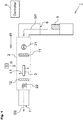
- Fig. 1 is a drawing illustrating a schematic configuration of a first embodiment of the gas treatment device.
- the gas treatment device 1 illustrated in Fig. 1 includes a treatment chamber 2 for gases to flow through, to perform a treatment to a gas to be treated G1 flowing through this treatment chamber 2 and to exhaust the gas as treated gas G2.
- the gas treatment device 1 includes an intake port 6 for introducing a gas to be treated G1 into the treatment chamber 2, and an exhaust port 7 for exhausting the gas (treated gas G2) after the treatment performed to the gas to be treated G1 in the treatment chamber 2.
- the gas treatment device 1 is used for gas treatment applications where the gas to be treated G1 is a mixture of air and VOCs.
- VOCs herein collectively refer to organic compounds that are volatile and become gases in the atmosphere, or a group of substances including but not limited to formaldehyde, methanol, IPA (isopropyl alcohol), acetone, ethylene oxide, toluene, xylene, and ethyl acetate.
- tissues or the like may be stored in a container filled with a formaldehyde solution (formalin) and securely positioned therein.
- formaldehyde solution formalin
- the lid of such a container When the lid of such a container is opened, it is expected that the highly volatile formaldehyde evaporates, resulting in the surrounding atmosphere containing formaldehyde which is a type of VOC.
- the formaldehyde solution in the tissue storage container may also contain a small amount of other VOC substances such as methanol. In such cases, not only formaldehyde but also other VOC substances will also be present in the air after the lid of the container has been opened.
- VOC emission source 9 represents a VOC emission source that is typically such a container or pharmaceutical. Hereinafter this will be referred to as "VOC emission source 9".
- the treatment chamber 2 includes therein a first filter 11, a second filter 12, an excimer lamp 3, a valve 21, and a blower 22.
- the gas treatment device 1 includes a controller 5 for controlling the valve 21 and blower 22.
- the degree of opening of the valve 21 and the operation of the blower 22 are controlled based on control signals i5 from the controller 5.
- control signals i5 from the controller 5.
- the blower 22 may be omitted and the valve 21 alone may be provided.
- the valve 21 and blower 22 may be manually controlled by an operator, rather than the control based on control signals i5 from the controller 5.
- valve 21 is depicted to be located closer to the intake port 6 than the blower 22, i.e., upstream in Fig. 1 , the positional relationship between the valve 21 and the blower 22 may be freely determined.
- valve 21 and blower 22 are provided inside the treatment chamber 2.
- the gas treatment device 1 includes the first filter 11, second filter 12, and excimer lamp 3 inside the treatment chamber 2. As illustrated in Fig. 1 , the first filter 11 is disposed closer to the intake port 6 than the excimer lamp 3, i.e., upstream, and the second filter 12 is disposed closer to the exhaust port 7 than the excimer lamp 3, i.e., downstream.
- the first filter 11 is a gas adsorption filter configured to be able to adsorb a first substance Z1 that belongs to VOCs in a gaseous form, and includes a porous adsorbent such as, for example, activated carbon, zeolite, silica gel, and so on.
- this first substance Z1 include substances containing the phenyl group such as toluene, xylene, styrene, and ethyl benzene, and substances that belong to alkyl chlorides such as chloroform, carbon tetrachloride, and so on.
- the gas to be treated G1 introduced from the intake port 6 is guided to the first filter 11. Any first substance Z1 that belongs to VOCs contained in the gas to be treated G1 is adsorbed and removed by the first filter 11. Consequently the concentration of the first substance Z1 contained in the gas to be treated G1 is lowered.
- Substances that belong to VOCs include substances that are hardly adsorbed by gas adsorption filters such as the first filter 11 mentioned above, and substances that are readily released even after adsorbed by the gas adsorption filter (hereinafter referred to as "second substance Z2").
- this second substance Z2 include aldehydes such as formaldehyde, epoxides such as ethylene oxide, alcohols such as methanol and isopropyl alcohol, and ketones such as acetone, methyl ethyl ketone, and methyl isobutyl ketone.
- the second substance Z2 has a higher saturation vapor pressure and a higher hydrophilicity than the first substance Z1.
- the gas to be treated G1 shows a high concentration of the contained second substance Z2 even after passing through the first filter 11.
- the gas to be treated G1 is guided as it is, i.e., with the high concentration of the contained second substance Z2, to the area where the excimer lamp 3 is disposed.
- the excimer lamp 3 has an arc tube 30 arranged longitudinally along the direction d1 in which the gas to be treated G1 flows (see Fig. 2).
- Fig. 2 is a drawing illustrating a schematic configuration of only the surroundings of the excimer lamp 3 inside a treatment chamber 2.
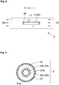
- Fig. 3 is a schematic cross-sectional view of the excimer lamp 3 illustrated in Fig. 2 cut in a plane orthogonal to the direction d1.
- the excimer lamp 3 has the arc tube 30 extending along the direction d1. More specifically, this arc tube 30 has an outer tube 30a that is cylindrical and positioned outside, and a cylindrical inner tube 30b disposed inside the outer tube 30a, coaxial with the outer tube 30a, and having a smaller inside diameter than that of the outer tube 30a. Both arc tubes 30 (30a, 30b) are made of a dielectric material such as synthetic quartz glass.
- the outer tube 30a and inner tube 30b are sealed at the ends in the direction d1 (not shown), so that between the tubes there is formed a light-emitting chamber that is annular when viewed from the direction d1.
- a discharge gas 33G that generates excimer molecules by an electric discharge is sealed in this light-emitting chamber.
- a more specific example of the discharge gas 33G is a gas mixture containing xenon (Xe) and neon (Ne) in a predetermined ratio (of, for example, 3:7), which may or may not further include a small amount of oxygen or hydrogen.
- the excimer lamp 3 of this embodiment includes a first electrode 31 set on an outer wall surface of the outer tube 30a, and a second electrode 32 set on an inner wall surface of the inner tube 30b.
- the first electrode 31 is in the form of a mesh or a wire.
- the second electrode 32 is in the form of a film.
- the second electrode 32 may also be in the form of a mesh or wire similar to the first electrode 31.
- the excimer lamp 3 has a base part 35 at one end in the direction d1 of the arc tube 30.
- This base part 35 is made of a ceramic material (inorganic material) such as steatite, forsterite, sialon, alumina, and the like, and serves the function of securing the end of the arc tube 30.
- Power supply lines (not shown) are each connected to the electrodes (31, 32) through a hole portion provided to the base part 35 or via an outer edge of the base part 35.
- the wavelength of the ultraviolet L1 can be changed by using a different substance for the discharge gas 33G.
- ArBr, ArCl, and F 2 can be used for the discharge gas 33G, which respectively produce light with a peak wavelength near 165 nm, 175 nm, and 153 nm.
- the description here assumes that the discharge gas 33G is a gas that contains Xe.
- the ultraviolet L1 emitted from the excimer lamp 3 having a peak wavelength of around A nm herein shall mean that the peak wavelength of the ultraviolet L1 is ( ⁇ - 2) nm or more and ( ⁇ + 2) nm or less.
- the first electrode 31 has a mesh or wire form so as not to inhibit emission of the ultraviolet L1 generated inside the arc tube 30 (more specifically, light-emitting chamber) out of the arc tube 30.
- the ultraviolet L1 is emitted out of the arc tube 30 through the gaps of the first electrode 31.
- the lamp power source of the excimer lamp 3 may also be controlled based on the control signal i5 from the controller 5.
- O( 1 D) represents oxygen atoms in the excited state
- O( 3 P) represents oxygen atoms in the ground state
- hv( ⁇ ) indicates absorption of light of a wavelength ⁇ .
- Oxygen atoms O( 3 P) generated by the reaction of Formula (2) react with the oxygen (O 2 ) contained in the gas to be treated G1 and generate ozone (O 3 ) by the reaction expressed by the following Formula (4).
- the gas to be treated G1 irradiated with the ultraviolet L1 produces highly reactive hydroxyl radicals ( ⁇ OH).
- the second substance Z2 that was not removed by the first filter 11 is therefore decomposed by the hydroxyl radicals ( ⁇ OH), so that the concentration of the second substance Z2 contained in the gas to be treated G1 is reduced.
- the gas to be treated G1 flowing near the excimer lamp 3 contains a VOC that can be decomposed by the ozone (O 3 )
- this VOC is decomposed by the ozone (O 3 ) generated by the reaction expressed by Formula (4) above.
- the gas to be treated G1 flows along the longitudinal direction of the arc tube 30, i.e., along the axis of the tube. This secures a certain time in which the gas to be treated G1 is irradiated with the ultraviolet L1 emitted from the arc tube 30 (excimer lamp 3). Accordingly, the gas to be treated G1 can be irradiated with a sufficient amount of ultraviolet L1 so that the VOC contained in the gas to be treated G1 can be decomposed even though the gas treatment device 1 has just one excimer lamp 3.
- the second filter 12 is a filter that can decompose ozone, for which structures wherein a catalyst is carried on a base member having a honeycomb structure made of metal such as aluminum and stainless steel, or ceramics, may be employed.
- a catalyst for the catalyst, rare metal catalysts such as palladium (Pd), rhodium (Rh), platinum (Pt) and the like, or metal oxides such as manganese dioxide (MnO 2 ), iron (II) oxide (Fe 2 O 3 ), nickel oxide (NiO) and the like may be used.
- the gas to be treated G1 after irradiated with the ultraviolet L1 from the excimer lamp 3 contains the ozone (O 3 ) that has been generated by the reaction expressed by Formula (4) above.
- the second filter 12 capable of decomposing ozone is disposed closer to the exhaust port 7 than the excimer lamp 3, i.e., downstream, so that the ozone contained in the gas to be treated G1 can be decomposed by this second filter 12. After passing through the second filter 12, the gas to be treated G1 is exhausted from the exhaust port 7 as a treated gas G2.
- the excimer lamp 3 was turned on, with an input power of 26.4 W from the lamp power source, and the illuminance on the surface of the arc tube 30 at point A in the middle in the direction d1 was measured with an illuminometer.
- air containing 10 ppm of xylene as a first substance Z1 that belongs to VOCs was introduced as the gas to be treated G1 from the intake port 6 into the treatment chamber 2 in a flow amount of 1000 L/min, and treated for a predetermined time, after which the illuminance at the point A was measured with an illuminometer.
- the changes with time in the illuminance are shown in Fig. 4 .
- Examples 1 to 3 all represent cases where treatment was performed to the gas to be treated G1 using the gas treatment device 1 illustrated in Fig. 1 . The test was conducted several times under the same conditions to show the reproducibility of the results.
- Comparative Examples 1 to 3 all represent cases where treatment was performed to the gas to be treated G1 using a gas treatment device 40 illustrated in Fig. 5 . The test was conducted several times under the same conditions to show the reproducibility of the results.
- the gas treatment device 40 that is Comparative Example 1 illustrated in Fig. 5 has the same elements as those of the gas treatment device 1 of Example 1 illustrated in Fig. 1 , except that the first filter 11 is removed.
- Fig. 4 indicates that the illuminance on the surface of the arc tube 30 declined largely as the processing time passes in the case with Comparative Examples 1 to 3. In contrast, it is seen that the illuminance on the surface of the arc tube 30 hardly declined even after continuous treatment of the gas to be treated G1 in Examples 1 to 3.
- the inventor discusses the reason for this as follows.
- Xylene as a first substance Z1 that belongs to VOCs, readily forms a secondary organic aerosol (SOA) when irradiated with ultraviolet L1 from the excimer lamp 3.
- SOA secondary organic aerosol
- the gas to be treated G1 containing xylene is guided toward the excimer lamp 3, and irradiated with the ultraviolet L1 from this excimer lamp 3. It is assumed that this resulted in formation of SOA, or secondary particles, from xylene, which adhered to the wall surface of the arc tube 30 of the excimer lamp 3, leading to the decline in the illuminance of the ultraviolet L1.
- the gas treatment device 1 of Example 1 includes the first filter 11 upstream of the excimer lamp 3 so that xylene contained in the gas to be treated G1 is adsorbed and removed by this first filter 11. Since the gas to be treated G1 guided toward the excimer lamp 3 contains a reduced concentration of xylene, there is hardly any xylene to form secondary particles when the gas to be treated G1 is irradiated with ultraviolet L1. It is therefore considered that the absence of secondary particles adhering on the wall surface of the arc tube 30 prevents the decline of illuminance of ultraviolet L1.
- Air containing xylene as the first substance Z1 that belongs to VOCs and formaldehyde as the second substance Z2 was introduced as the gas to be treated G1 into both of the gas treatment device 1 of Example 1 and the gas treatment device 40 of Comparative Example 1, and the treatment was performed similarly to the process described above. It was confirmed that, while the illuminance of the ultraviolet L1 reduced with time in the gas treatment device 40 of Comparative Example 1, the decline in the illuminance of ultraviolet L1 was inhibited in the gas treatment device 1 of Example 1, similarly to the results shown in Fig. 4 .
- a second embodiment of the gas treatment device according to the present invention will be described, mainly centering on the points different from the first embodiment.
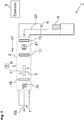
- the gas treatment device 1 illustrated in Fig. 6 is different in that it includes a circulation flow path 8, as compared to the first embodiment.
- the circulation flow path 8 is a flow path for introducing the gas to be treated G1 after having been treated in the treatment chamber 2 (treated gas G2) again into the intake port 6.
- the circulation flow path 8 includes a valve 8A, whose degree of opening can be controlled based on the control signal i5 from the controller 5. The degree of opening of this valve 8A is adjusted so that the treated gas G2 is introduced into the circulation flow path 8, or not, and/or the flow amount of the treated gas is adjusted.
- the gas treatment device 1 of this embodiment may further include a blower inside the circulation flow path 8 for adjusting the flow amount.
- the gas treatment device 1 of this embodiment includes a third filter 13 closer to the intake port 6 than the first filter 11, i.e., upstream, inside the treatment chamber 2.
- This third filter 13 is provided for the purpose of removing dust contained in the gas to be treated G1, and may be a medium efficiency particulate air filter.
- the third filter 13 even when the gas to be treated G1 contains dust, it is less likely that the first filter 11, which is provided for the purpose of adsorbing the first substance Z1 belonging to VOCs in the gaseous form, loses the capability of adsorbing the first substance Z1, which may be caused by adhesion of dust on the first filter 11.
- the third filter also reduces the possibility of some dust passing through the first filter 11 and adhering to the wall surface of the arc tube 30 of the excimer lamp 3, which would cause a decline in the illuminance of the ultraviolet L1.
- irradiation of the gas to be treated G1 with ultraviolet L1 produces ozone (O 3 ).
- the ozone (O 3 ) that was not used for the decomposition of VOCs stays in the gas to be treated G1 and is guided toward the exhaust port 7. Since the second filter 12 for decomposition of ozone is disposed downstream of the excimer lamp 3 as described above, the treated gas G2 after passing through the second filter 12 contains a reduced concentration of ozone.
- the ozone (O 3 ) contained in the gas to be treated G1 could not completely be removed by the second filter 12 and that the treated gas G2 still contains some ozone (O 3 ).
- the ozone may damage the third filter 13 when the gas to be treated G1 containing ozone passes through the third filter 13.
- the third filter 13 should preferably be an ozone-resistant filter.
- a non-woven fabric filter made of polyester fiber, fluoride fiber, glass fiber, and the like may be used as this filter.
Landscapes
- Chemical & Material Sciences (AREA)
- Engineering & Computer Science (AREA)
- Analytical Chemistry (AREA)
- General Chemical & Material Sciences (AREA)
- Oil, Petroleum & Natural Gas (AREA)
- Chemical Kinetics & Catalysis (AREA)
- Disinfection, Sterilisation Or Deodorisation Of Air (AREA)
- Treating Waste Gases (AREA)
Abstract
Description
- The present invention relates to a gas treatment device, and more particularly to a gas treatment device for treating a gas to be treated containing VOCs (Volatile Organic Compounds).
- Gases that can affect the global environment and the human body have been an issue in recent years, and certain regulations are imposed on exhaust gases from automobiles and factories. Regulations are imposed on VOC emissions also in many indoor applications where specified pharmaceuticals may be used, such as test facilities and clinical settings.
-
Patent Document 1 specified below discloses a gas treatment device that treats a gas to be treated by irradiating air containing VOCs with ultraviolet.Fig. 11 is a drawing illustrating a schematic configuration of the gas treatment device disclosed inPatent Document 1. As illustrated inFig. 11 , thegas treatment device 100 includes aflow path 101 for VOC-containing air G100 that is the object of treatment to flow through, anultraviolet light source 102 disposed inside the flow path, aparticulate filter 103, and an ozone-decomposing filter 104. - The following description is found in
Patent Document 1. Irradiation of the VOC-containing air to be treated G100 that flows through theflow path 101 with ultraviolet L102 having a wavelength of 185 nm from theultraviolet light source 102 produces ozone (O3) from the oxygen (O2) contained in the air G100. This ozone accelerates chemical reactions of VOCs, whereby particles of secondary product are generated. The secondary product particles are removed by theparticulate filter 103 disposed downstream of theultraviolet light source 102. The ozone that was generated by ultraviolet L102 irradiation is removed by the ozone-decomposing filter 104 disposed downstream of theultraviolet light source 102. The treated air G101 after passing through both filters (103, 104) is thus cleared of VOCs. -
Patent Document 1 mentions toluene, xylene, and ethyl acetate as examples of VOCs. - Patent Document 1:
JP-A-2018-89106 - Substances that belong to VOCs include types that hardly form particles when irradiated with ultraviolet and that can hardly be broken down even by ozone, such as formaldehyde. If the air to be treated G100 contains formaldehyde, for example, the
gas treatment device 100 described inPatent Document 1 is not able to remove formaldehyde sufficiently. Thegas treatment device 100 therefore will exhaust the treated air G101, from which formaldehyde is not fully removed, which is undesirable. - The inventor investigated a method of decomposing formaldehyde using the
gas treatment device 100 illustrated inFig. 11 , wherein a xenon excimer lamp was used as theultraviolet light source 102 to irradiate the air to be treated G100 with ultraviolet L102 having shorter wavelengths so that hydroxyl radicals (·OH) that are more reactive than ozone are generated to be used for decomposition of formaldehyde. It was found, however, that this method entailed the problem of contaminants deposited on the wall of the arc tube (tube body) of the excimer lamp, which is used as theultraviolet light source 102, as the treatment of the air G100 progresses, resulting in lowered illuminance of the ultraviolet L102. This phenomenon lowers the radical formation potential and compromises the VOC decomposition capability, which is not preferable. - In view of the problems described above, an object of the present invention is to realize a gas treatment device that performs a treatment to a flowing gas to be treated, which is air containing a VOC, the device being capable of treating even a gas containing a substance that is hardly decomposed by ozone, and capable of keeping treatment capacity over time.
- The present invention provides a gas treatment device performing a treatment to a gas to be treated that is a mixture of air and a VOC flowing through a treatment chamber. The device includes:
- an intake port allowing the gas to be treated to be introduced into the treatment chamber;
- an exhaust port allowing the gas to be treated to be exhausted after being treated inside the treatment chamber;
- a first filter disposed inside the treatment chamber and configured to be able to adsorb a first substance belonging to VOCs in a gaseous form; and
- an excimer lamp disposed closer to the exhaust port than the first filter inside the treatment chamber and irradiating the gas to be treated with ultraviolet after the gas to be treated has passed through the first filter to allow a second substance belonging to VOCs to be decomposed.
- The first substance has a higher adsorbability to the first filter in a gaseous form and a higher aerosol formation potential when irradiated with the ultraviolet than the second substance.
- The phrase "aerosol formation potential" herein is defined as the yield of secondary organic aerosols (SOAs) per unit amount of consumed VOC, and used as the index of how readily SOA is generated for each substance that forms a VOC. More specifically, the yield is defined by the value Y as expressed by the following Formula (1). In Formula (1), Mo represents the aerosol concentration [µg/m3], and ΔVOC represents the amount of VOC [ppb] consumed in the (photochemical) reaction.

- In the configuration above, a first filter is disposed closer to the intake port than the excimer lamp, i.e., upstream, inside the treatment chamber. Therefore, when a gas that is air containing a first substance and a second substance that belong to VOCs is introduced from the intake port into the treatment chamber as the gas to be treated, this gas passes through the first filter before irradiated with ultraviolet from the excimer lamp. As a result, the first substance contained in the gas to be treated is adsorbed by the first filter, and the gas to be treated with a much reduced concentration of the first substance is irradiated with the ultraviolet from the excimer lamp.
- Therefore, even if the first substance is a substance that shows a high aerosol formation potential when irradiated with ultraviolet, by the time the gas to be treated passes near the excimer lamp, the first substance has already been removed, so that adhesion of aerosol particles originating from the first substance on the tube body of the excimer lamp is inhibited.
- In cases where the second substance is a substance with a low adsorbability, i.e., hardly removable by the first filter, the gas to be treated after having passed through the first filter still contains the second substance therein. However, this gas to be treated is irradiated with the ultraviolet from the excimer lamp, so that the second substance is decomposed by radicals generated when the oxygen contained in the gas to be treated is decomposed. As a result, the concentrations of both the first substance and the second substance can be reduced before the air is exhausted from the exhaust port.
- Since adhesion of aerosol particles originating from the first substance on the tube wall of the arc tube of the excimer lamp is inhibited as described above, the illuminance of ultraviolet emitted from the excimer lamp hardly declines as time passes. Consequently, a decline over time in the capacity to treat VOCs contained in the gas to be treated is inhibited.
- The first filter is configured as a gas adsorption filter that includes a porous adsorbent such as, for example, activated carbon, zeolite, silica gel, and so on.
- The first substance may either contain a phenyl group or belong to alkyl chlorides, and
the second substance may belong to any one of alcohols, ketones, aldehydes, and epoxides. - For example,
the first substance may be one or more of substances included in the group consisting of toluene, xylene, styrene, ethyl benzene, chloroform, and carbon tetrachloride, and
the second substance may be one or more of substances included in the group consisting of formaldehyde, ethylene oxide, methanol, isopropyl alcohol, acetone, methyl ethyl ketone, and methyl isobutyl ketone. - The excimer lamp may include an arc tube hermetically filled with a discharge gas containing Xe and arranged longitudinally along a direction in which the gas to be treated flows.
- With this configuration, the excimer lamp emits ultraviolet having a peak wavelength of 160 nm or more and less than 200 nm to irradiate the gas to be treated. This enhances the formation efficiency of hydroxyl radicals (·OH) that are particularly reactive, and this way, a gas treatment device with excellent capability to decompose the second substance is realized. The excimer lamp is disposed inside the treatment chamber such that the arc tube in the excimer lamp extends longitudinally along the direction in which the gas to be treated flows, so that the gas to be treated flowing through the treatment chamber can be irradiated with ultraviolet over a length of time required for the gas to be treated to move a distance corresponding to the length of the tube body (more particularly, emission length). This allows the gas to be treated to be irradiated with a sufficient amount of ultraviolet so that a high concentration of radicals including hydroxyl radicals (·OH) are generated to contribute to decomposition of the second substance.
- The gas treatment device may further include a second filter disposed closer to the exhaust port than the excimer lamp inside the treatment chamber and capable of decomposing ozone.
- Irradiation of the gas to be treated with the ultraviolet from the excimer lamp produces radicals such as hydroxyl radicals (·OH) as well as ozone (O3). This ozone is less reactive than radicals and may be left in the gas to be treated and discharged from the exhaust port. Since ozone is a substance hazardous to the human body, it is preferable to reduce the concentration of ozone emission to the outside of the gas treatment device.
- In the configuration above, a second filter is disposed closer to the exhaust port than the excimer lamp, i.e., downstream of the excimer lamp. Therefore, the ozone generated when the gas to be treated is irradiated with ultraviolet from the excimer lamp is decomposed by the second filter, so that the air discharged from the exhaust port contains a low concentration of ozone, as well as a low concentration of VOCs.
- For the second filter, structures wherein a catalyst is carried on a base member having a honeycomb structure made of metal such as aluminum and stainless steel, or ceramics, may be employed. For the catalyst, rare metal catalysts such as palladium (Pd), rhodium (Rh), platinum (Pt) and the like, or metal oxides such as manganese dioxide (MnO2), iron (II) oxide (Fe2O3), nickel oxide (NiO) and the like may be used.
- The gas treatment device may further include an ozone-resistant third filter disposed closer to the intake port than the first filter inside the treatment chamber and capable of adsorbing dust contained in the gas to be treated.
- There may be cases where the gas to be treated introduced from the intake port initially contains dust particles. By providing the third filter closer to the intake port than the first filter, i.e., upstream, inside the treatment chamber, the dust can be removed upstream of the first filter. For the third filter, a medium efficiency particulate air filter may be used, for example. A "medium efficiency particulate air filter" means a filter that has a medium level particulate filtration efficiency to particulates primarily of a particle size of 0.5 pm or more and less than 5 pm, i.e., a filter having a filtration efficiency of 50% to less than 95% as measured by a dust spot method (JIS B 9908).
- The gas treatment device may further include a circulation flow path that introduces at least part of the gas to be treated that has passed through the second filter to a point between the third filter and the intake port.
- The air containing VOCs, or the gas to be treated, is treated as described above, wherein the first filter removes the first substance, which is a type of VOC, and radicals generated by ultraviolet radiation from the excimer lamp decompose the second substance, which is another type of VOC. Depending on the place where the gas treatment device is installed, however, there can be a case where the concentration of VOCs contained in the air discharged from the exhaust port is desired to be even lower than a value set in accordance with common environmental standards.
- According to the configuration described above, the gas treatment device includes a circulation flow path, so that the air that has undergone the process of removing VOCs in the treatment chamber can be guided again to the first filter and excimer lamp through the circulation flow path. The air can thus be passed through the first filter a number of times to remove the first substance in the air even more, and can be irradiated with ultraviolet from the excimer lamp a number of times to remove the second substance in the air even more.
- Irradiation of the air or the gas to be treated with ultraviolet from the excimer lamp generates not only radicals but also ozone, as described above. While the second filter is disposed downstream of the excimer lamp for decomposing the ozone, the ozone contained in the gas to be treated may not necessarily be entirely decomposed, and part of the ozone may possibly pass through the second filter. This can occur easily in particular in a case where the gas to be treated flows fast.
- In such a case, if the gas treatment device includes the circulation flow path, the gas to be treated containing ozone is guided toward the third filter mentioned above. If the third filter is an air filter that is not resistant to ozone, there is a risk that the third filter may be damaged by the ozone, in which case the substances making up the third filter may adhere to the tube wall of the arc tube of the excimer lamp. In this respect, the configuration described above prevents such damage caused by ozone, since the third filter is ozone-resistant.
- The third filter, specifically, is a non-woven fabric filter made of polyester fiber, fluoride fiber, glass fiber, and the like.
- The gas treatment device may further include an ozone-resistant fourth filter disposed between the first filter and the excimer lamp inside the treatment chamber and capable of adsorbing dust contained in the gas to be treated.
- The present invention realizes a gas treatment device capable of treating a gas to be treated even when the gas contains a substance belonging to VOCs that is hardly decomposed by ozone, and capable of keeping treatment capacity over time.
-
-
Fig. 1 is a drawing illustrating a schematic configuration of a first embodiment of the gas treatment device; -
Fig. 2 is a drawing illustrating a schematic configuration of only the surroundings of an excimer lamp inside a light-emitting chamber; -
Fig. 3 is a schematic cross-sectional view of the excimer lamp illustrated inFig. 2 cut in a plane orthogonal to the direction d1; -
Fig. 4 is a graph showing changes with time in the illuminance on the surface of the tube body of the excimer lamp in the gas treatment devices of Examples and Comparative Examples; -
Fig. 5 is a drawing illustrating a schematic configuration of the gas treatment device of Comparative Examples; -
Fig. 6 is a drawing illustrating a schematic configuration of a second embodiment of the gas treatment device; -
Fig. 7 is a drawing illustrating a schematic configuration of the gas treatment device in another embodiment; -
Fig. 8 is a drawing illustrating a schematic configuration of the gas treatment device in another embodiment; -
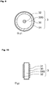
Fig. 9 is a schematic cross-sectional view of the excimer lamp in a gas treatment device of another embodiment cut in a plane orthogonal to the direction d1; -
Fig. 10 is a schematic cross-sectional view of the excimer lamp in a gas treatment device of another embodiment cut in a plane orthogonal to the direction d1; and -
Fig. 11 is a drawing illustrating a schematic configuration of an existing gas treatment device. - Embodiments of the gas treatment device according to the present invention will be described with reference to applicable drawings. The drawings referred to below each present a schematic illustration and the dimensional ratios in the drawings are not necessarily the same as the actual dimensional ratios. The dimensional ratios in various figures of the drawings are not necessarily the same, either.
- A first embodiment of a gas treatment device according to the present invention will be described below with reference to applicable drawings.
-
Fig. 1 is a drawing illustrating a schematic configuration of a first embodiment of the gas treatment device. Thegas treatment device 1 illustrated inFig. 1 includes atreatment chamber 2 for gases to flow through, to perform a treatment to a gas to be treated G1 flowing through thistreatment chamber 2 and to exhaust the gas as treated gas G2. - The
gas treatment device 1 includes anintake port 6 for introducing a gas to be treated G1 into thetreatment chamber 2, and anexhaust port 7 for exhausting the gas (treated gas G2) after the treatment performed to the gas to be treated G1 in thetreatment chamber 2. - The
gas treatment device 1 is used for gas treatment applications where the gas to be treated G1 is a mixture of air and VOCs. VOCs herein collectively refer to organic compounds that are volatile and become gases in the atmosphere, or a group of substances including but not limited to formaldehyde, methanol, IPA (isopropyl alcohol), acetone, ethylene oxide, toluene, xylene, and ethyl acetate. - In test facilities or clinical settings, for example, tissues or the like may be stored in a container filled with a formaldehyde solution (formalin) and securely positioned therein. When the lid of such a container is opened, it is expected that the highly volatile formaldehyde evaporates, resulting in the surrounding atmosphere containing formaldehyde which is a type of VOC. In some cases, the formaldehyde solution in the tissue storage container may also contain a small amount of other VOC substances such as methanol. In such cases, not only formaldehyde but also other VOC substances will also be present in the air after the lid of the container has been opened.
- Generally, in test facilities or clinical settings, pharmaceuticals containing VOC substances such as formaldehyde or xylene may be used not just for the purpose of storing tissues. In
Fig. 1 ,reference numeral 9 represents a VOC emission source that is typically such a container or pharmaceutical. Hereinafter this will be referred to as "VOC emission source 9". - In this embodiment, the
treatment chamber 2 includes therein afirst filter 11, asecond filter 12, anexcimer lamp 3, avalve 21, and ablower 22. - The
gas treatment device 1 includes acontroller 5 for controlling thevalve 21 andblower 22. The degree of opening of thevalve 21 and the operation of theblower 22 are controlled based on control signals i5 from thecontroller 5. By controlling thesevalve 21 andblower 22, the flow amount and the flow rate of the gas to be treated G1 flowing through thetreatment chamber 2 are adjusted. - When it is only necessary to control whether or not the gas to be treated G1 is allowed to flow through the
treatment chamber 2, theblower 22 may be omitted and thevalve 21 alone may be provided. Thevalve 21 andblower 22 may be manually controlled by an operator, rather than the control based on control signals i5 from thecontroller 5. - While the
valve 21 is depicted to be located closer to theintake port 6 than theblower 22, i.e., upstream inFig. 1 , the positional relationship between thevalve 21 and theblower 22 may be freely determined. - In the following description, it is assumed that both the
valve 21 andblower 22 are provided inside thetreatment chamber 2. - The
gas treatment device 1 includes thefirst filter 11,second filter 12, andexcimer lamp 3 inside thetreatment chamber 2. As illustrated inFig. 1 , thefirst filter 11 is disposed closer to theintake port 6 than theexcimer lamp 3, i.e., upstream, and thesecond filter 12 is disposed closer to theexhaust port 7 than theexcimer lamp 3, i.e., downstream. - The
first filter 11 is a gas adsorption filter configured to be able to adsorb a first substance Z1 that belongs to VOCs in a gaseous form, and includes a porous adsorbent such as, for example, activated carbon, zeolite, silica gel, and so on. Examples of this first substance Z1 include substances containing the phenyl group such as toluene, xylene, styrene, and ethyl benzene, and substances that belong to alkyl chlorides such as chloroform, carbon tetrachloride, and so on. - The gas to be treated G1 introduced from the
intake port 6 is guided to thefirst filter 11. Any first substance Z1 that belongs to VOCs contained in the gas to be treated G1 is adsorbed and removed by thefirst filter 11. Consequently the concentration of the first substance Z1 contained in the gas to be treated G1 is lowered. - Substances that belong to VOCs include substances that are hardly adsorbed by gas adsorption filters such as the
first filter 11 mentioned above, and substances that are readily released even after adsorbed by the gas adsorption filter (hereinafter referred to as "second substance Z2"). Examples of this second substance Z2 include aldehydes such as formaldehyde, epoxides such as ethylene oxide, alcohols such as methanol and isopropyl alcohol, and ketones such as acetone, methyl ethyl ketone, and methyl isobutyl ketone. The second substance Z2 has a higher saturation vapor pressure and a higher hydrophilicity than the first substance Z1. When a second substance Z2 is contained in the gas to be treated G1, the gas to be treated G1 shows a high concentration of the contained second substance Z2 even after passing through thefirst filter 11. After passing through thefirst filter 11, the gas to be treated G1 is guided as it is, i.e., with the high concentration of the contained second substance Z2, to the area where theexcimer lamp 3 is disposed. - The
excimer lamp 3 has anarc tube 30 arranged longitudinally along the direction d1 in which the gas to be treated G1 flows (seeFig. 2). Fig. 2 is a drawing illustrating a schematic configuration of only the surroundings of theexcimer lamp 3 inside atreatment chamber 2.Fig. 3 is a schematic cross-sectional view of theexcimer lamp 3 illustrated inFig. 2 cut in a plane orthogonal to the direction d1. - In this embodiment, the
excimer lamp 3 has thearc tube 30 extending along the direction d1. More specifically, thisarc tube 30 has anouter tube 30a that is cylindrical and positioned outside, and a cylindricalinner tube 30b disposed inside theouter tube 30a, coaxial with theouter tube 30a, and having a smaller inside diameter than that of theouter tube 30a. Both arc tubes 30 (30a, 30b) are made of a dielectric material such as synthetic quartz glass. - The
outer tube 30a andinner tube 30b are sealed at the ends in the direction d1 (not shown), so that between the tubes there is formed a light-emitting chamber that is annular when viewed from the direction d1. Adischarge gas 33G that generates excimer molecules by an electric discharge is sealed in this light-emitting chamber. A more specific example of thedischarge gas 33G is a gas mixture containing xenon (Xe) and neon (Ne) in a predetermined ratio (of, for example, 3:7), which may or may not further include a small amount of oxygen or hydrogen. - The
excimer lamp 3 of this embodiment includes afirst electrode 31 set on an outer wall surface of theouter tube 30a, and asecond electrode 32 set on an inner wall surface of theinner tube 30b. Thefirst electrode 31 is in the form of a mesh or a wire. Thesecond electrode 32 is in the form of a film. Thesecond electrode 32 may also be in the form of a mesh or wire similar to thefirst electrode 31. - In the example illustrated in
Fig. 2 , theexcimer lamp 3 has abase part 35 at one end in the direction d1 of thearc tube 30. Thisbase part 35 is made of a ceramic material (inorganic material) such as steatite, forsterite, sialon, alumina, and the like, and serves the function of securing the end of thearc tube 30. Power supply lines (not shown) are each connected to the electrodes (31, 32) through a hole portion provided to thebase part 35 or via an outer edge of thebase part 35. - When a high-frequency AC voltage of about 50 kHz to 5 MHz, for example, is applied between the
first electrode 31 and thesecond electrode 32 via the power supply lines from a lamp power source (not shown) of theexcimer lamp 3, this voltage is applied to thedischarge gas 33G via thearc tube 30. This generates a discharge plasma inside the discharge chamber filled with thedischarge gas 33G, and excited atoms of thedischarge gas 33G form excimers, which, when transiting to the ground state, emit light. In the case where a gas containing xenon (Xe) mentioned above is used as thedischarge gas 33G, the excimer emits ultraviolet L1 (seeFig. 2 ) that has a peak wavelength near 172 nm. - The wavelength of the ultraviolet L1 can be changed by using a different substance for the
discharge gas 33G. For example, ArBr, ArCl, and F2 can be used for thedischarge gas 33G, which respectively produce light with a peak wavelength near 165 nm, 175 nm, and 153 nm. The description here assumes that thedischarge gas 33G is a gas that contains Xe. - The ultraviolet L1 emitted from the
excimer lamp 3 having a peak wavelength of around A nm herein shall mean that the peak wavelength of the ultraviolet L1 is (λ - 2) nm or more and (λ + 2) nm or less. - As described above, the
first electrode 31 has a mesh or wire form so as not to inhibit emission of the ultraviolet L1 generated inside the arc tube 30 (more specifically, light-emitting chamber) out of thearc tube 30. Thus the ultraviolet L1 is emitted out of thearc tube 30 through the gaps of thefirst electrode 31. - The lamp power source of the
excimer lamp 3 may also be controlled based on the control signal i5 from thecontroller 5. - Irradiation of the gas to be treated G1 containing VOCs flowing through the
treatment chamber 2 with the ultraviolet L1 from theexcimer lamp 3 generates highly reactive oxygen atoms O(1D) and hydroxyl radicals (·OH) by the reactions expressed by the following Formulas (2) and (3). In the following formulas, O(1D) represents oxygen atoms in the excited state, and O(3P) represents oxygen atoms in the ground state. hv(λ) indicates absorption of light of a wavelength λ.
O2 + hv(λ) → O(1D) + O(3P) .... (2)
O(1D) + H2O → ·OH + ·OH .... (3)
- Oxygen atoms O(3P) generated by the reaction of Formula (2) react with the oxygen (O2) contained in the gas to be treated G1 and generate ozone (O3) by the reaction expressed by the following Formula (4).
O(3P) + O2 → O3 .... (4)
- Namely, the gas to be treated G1 irradiated with the ultraviolet L1 produces highly reactive hydroxyl radicals (·OH). The second substance Z2 that was not removed by the
first filter 11 is therefore decomposed by the hydroxyl radicals (·OH), so that the concentration of the second substance Z2 contained in the gas to be treated G1 is reduced. If the gas to be treated G1 flowing near theexcimer lamp 3 contains a VOC that can be decomposed by the ozone (O3), this VOC is decomposed by the ozone (O3) generated by the reaction expressed by Formula (4) above. - As mentioned above with reference to
Fig. 2 , the gas to be treated G1 flows along the longitudinal direction of thearc tube 30, i.e., along the axis of the tube. This secures a certain time in which the gas to be treated G1 is irradiated with the ultraviolet L1 emitted from the arc tube 30 (excimer lamp 3). Accordingly, the gas to be treated G1 can be irradiated with a sufficient amount of ultraviolet L1 so that the VOC contained in the gas to be treated G1 can be decomposed even though thegas treatment device 1 has just oneexcimer lamp 3. - After the concentrations of the first substance Z1 and the second substance Z2 have been lowered, the gas to be treated G1 is guided toward the
second filter 12. Thesecond filter 12 is a filter that can decompose ozone, for which structures wherein a catalyst is carried on a base member having a honeycomb structure made of metal such as aluminum and stainless steel, or ceramics, may be employed. For the catalyst, rare metal catalysts such as palladium (Pd), rhodium (Rh), platinum (Pt) and the like, or metal oxides such as manganese dioxide (MnO2), iron (II) oxide (Fe2O3), nickel oxide (NiO) and the like may be used. - As mentioned above, there may be a case where the gas to be treated G1 after irradiated with the ultraviolet L1 from the
excimer lamp 3 contains the ozone (O3) that has been generated by the reaction expressed by Formula (4) above. In thegas treatment device 1 of this embodiment, however, thesecond filter 12 capable of decomposing ozone is disposed closer to theexhaust port 7 than theexcimer lamp 3, i.e., downstream, so that the ozone contained in the gas to be treated G1 can be decomposed by thissecond filter 12. After passing through thesecond filter 12, the gas to be treated G1 is exhausted from theexhaust port 7 as a treated gas G2. - The following tests were conducted to illustrate the effects of the
gas treatment device 1 of this embodiment. - First, before introduction of a gas to be treated G1, the
excimer lamp 3 was turned on, with an input power of 26.4 W from the lamp power source, and the illuminance on the surface of thearc tube 30 at point A in the middle in the direction d1 was measured with an illuminometer. - Next, air containing 10 ppm of xylene as a first substance Z1 that belongs to VOCs was introduced as the gas to be treated G1 from the
intake port 6 into thetreatment chamber 2 in a flow amount of 1000 L/min, and treated for a predetermined time, after which the illuminance at the point A was measured with an illuminometer. The changes with time in the illuminance are shown inFig. 4 . - In
Fig. 4 , Examples 1 to 3 all represent cases where treatment was performed to the gas to be treated G1 using thegas treatment device 1 illustrated inFig. 1 . The test was conducted several times under the same conditions to show the reproducibility of the results. InFig. 4 , Comparative Examples 1 to 3 all represent cases where treatment was performed to the gas to be treated G1 using agas treatment device 40 illustrated inFig. 5 . The test was conducted several times under the same conditions to show the reproducibility of the results. Thegas treatment device 40 that is Comparative Example 1 illustrated inFig. 5 has the same elements as those of thegas treatment device 1 of Example 1 illustrated inFig. 1 , except that thefirst filter 11 is removed. -
Fig. 4 indicates that the illuminance on the surface of thearc tube 30 declined largely as the processing time passes in the case with Comparative Examples 1 to 3. In contrast, it is seen that the illuminance on the surface of thearc tube 30 hardly declined even after continuous treatment of the gas to be treated G1 in Examples 1 to 3. - The inventor discusses the reason for this as follows.
- Xylene, as a first substance Z1 that belongs to VOCs, readily forms a secondary organic aerosol (SOA) when irradiated with ultraviolet L1 from the
excimer lamp 3. In thegas treatment device 40 of Comparative Example 1 illustrated inFig. 5 , the gas to be treated G1 containing xylene is guided toward theexcimer lamp 3, and irradiated with the ultraviolet L1 from thisexcimer lamp 3. It is assumed that this resulted in formation of SOA, or secondary particles, from xylene, which adhered to the wall surface of thearc tube 30 of theexcimer lamp 3, leading to the decline in the illuminance of the ultraviolet L1. - In contrast, the
gas treatment device 1 of Example 1 includes thefirst filter 11 upstream of theexcimer lamp 3 so that xylene contained in the gas to be treated G1 is adsorbed and removed by thisfirst filter 11. Since the gas to be treated G1 guided toward theexcimer lamp 3 contains a reduced concentration of xylene, there is hardly any xylene to form secondary particles when the gas to be treated G1 is irradiated with ultraviolet L1. It is therefore considered that the absence of secondary particles adhering on the wall surface of thearc tube 30 prevents the decline of illuminance of ultraviolet L1. - Air containing xylene as the first substance Z1 that belongs to VOCs and formaldehyde as the second substance Z2 was introduced as the gas to be treated G1 into both of the
gas treatment device 1 of Example 1 and thegas treatment device 40 of Comparative Example 1, and the treatment was performed similarly to the process described above. It was confirmed that, while the illuminance of the ultraviolet L1 reduced with time in thegas treatment device 40 of Comparative Example 1, the decline in the illuminance of ultraviolet L1 was inhibited in thegas treatment device 1 of Example 1, similarly to the results shown inFig. 4 . - A second embodiment of the gas treatment device according to the present invention will be described, mainly centering on the points different from the first embodiment.
- The
gas treatment device 1 illustrated inFig. 6 is different in that it includes acirculation flow path 8, as compared to the first embodiment. Thecirculation flow path 8 is a flow path for introducing the gas to be treated G1 after having been treated in the treatment chamber 2 (treated gas G2) again into theintake port 6. In the example illustrated inFig. 6 , thecirculation flow path 8 includes avalve 8A, whose degree of opening can be controlled based on the control signal i5 from thecontroller 5. The degree of opening of thisvalve 8A is adjusted so that the treated gas G2 is introduced into thecirculation flow path 8, or not, and/or the flow amount of the treated gas is adjusted. - Although not illustrated in
Fig. 6 , thegas treatment device 1 of this embodiment may further include a blower inside thecirculation flow path 8 for adjusting the flow amount. - As illustrated in
Fig. 6 , thegas treatment device 1 of this embodiment includes athird filter 13 closer to theintake port 6 than thefirst filter 11, i.e., upstream, inside thetreatment chamber 2. Thisthird filter 13 is provided for the purpose of removing dust contained in the gas to be treated G1, and may be a medium efficiency particulate air filter. With thethird filter 13, even when the gas to be treated G1 contains dust, it is less likely that thefirst filter 11, which is provided for the purpose of adsorbing the first substance Z1 belonging to VOCs in the gaseous form, loses the capability of adsorbing the first substance Z1, which may be caused by adhesion of dust on thefirst filter 11. The third filter also reduces the possibility of some dust passing through thefirst filter 11 and adhering to the wall surface of thearc tube 30 of theexcimer lamp 3, which would cause a decline in the illuminance of the ultraviolet L1. - As described above, irradiation of the gas to be treated G1 with ultraviolet L1 produces ozone (O3). The ozone (O3) that was not used for the decomposition of VOCs stays in the gas to be treated G1 and is guided toward the
exhaust port 7. Since thesecond filter 12 for decomposition of ozone is disposed downstream of theexcimer lamp 3 as described above, the treated gas G2 after passing through thesecond filter 12 contains a reduced concentration of ozone. - Even so, it is possible that the ozone (O3) contained in the gas to be treated G1 could not completely be removed by the
second filter 12 and that the treated gas G2 still contains some ozone (O3). In such a case, when the treated gas G2 is introduced into theintake port 6 again as a gas to be treated G1 through thecirculation flow path 8 as in thegas treatment device 1 of this embodiment, the ozone may damage thethird filter 13 when the gas to be treated G1 containing ozone passes through thethird filter 13. From this viewpoint, thethird filter 13 should preferably be an ozone-resistant filter. A non-woven fabric filter made of polyester fiber, fluoride fiber, glass fiber, and the like may be used as this filter. - Other embodiments are described below.
- <1> The
gas treatment device 1 of the first embodiment may include athird filter 13 for removing dust, as illustrated inFig. 7 .
Thegas treatment device 1 may not include thesecond filter 12 inside thetreatment chamber 2, as illustrated inFig. 8 . If, for example, a means for decomposing ozone is disposed downstream of theexhaust port 7, or if the concentration of ozone to be generated inside thetreatment chamber 2 is expected to be less than a reference value, thesecond filter 12 need not necessarily be provided. - <2> In the embodiments described above, the
excimer lamp 3 includes anarc tube 30 hermetically filled with a discharge gas containing Xe. In this case, as mentioned above, theexcimer lamp 3 emits ultraviolet L1 having a peak wavelength at around 172 nm. Irradiation of the gas to be treated G1 with this ultraviolet L1 causes the reactions expressed by Formulas (2) and (3) mentioned above, generating highly reactive hydroxyl radicals (·OH), which decompose the second substance Z2 that belongs to VOCs.
As mentioned above, the wavelength of the ultraviolet L1 may be changed by using a different kind of discharge gas sealed in thearc tube 30 of theexcimer lamp 3. The reaction expressed by Formula (2) above readily occurs when the wavelength λ of the ultraviolet L1 is 180 nm or less, in particular. On the other hand, when the wavelength λ of the ultraviolet L1 is longer than 180 nm, a reaction expressed by the following Formula (2a), rather than Formula (2), occurs more readily.
O2 + hv(λ) → O(3P) + O(3P) .... (2a)
Oxygen atoms O(3P) generated by the reaction expressed by this Formula (2a) react with the oxygen (O2) contained in the gas to be treated G1 and generate ozone (O3) by the reaction expressed by the Formula (4) above.
Namely, if the second substance Z2 belonging to VOCs and contained in the gas to be treated G1 is a substance that can be decomposed by ozone (O3), theexcimer lamp 3 may be configured to emit ultraviolet L1 having a peak wavelength of longer than 180 nm. Any first substance Z1 belonging to VOCs and contained in the gas to be treated G1 is removed by thefirst filter 11, while the second substance Z2 is decomposed and removed by the ozone, in such a configuration, too.
Since the first substance Z1 having a high aerosol formation potential is removed by thefirst filter 11 before the ultraviolet L1 irradiation, adhesion of secondary particles on the surface of thearc tube 30 of theexcimer lamp 3 is inhibited. - <3> The configuration of the
excimer lamp 3 is not limited to the form illustrated inFig. 3 . The lamp may have a shape such as the one illustrated inFig. 9 or Fig. 10 , for example.Fig. 9 and Fig. 10 are schematic cross-sectional views ofexcimer lamps 3 of respectivegas treatment devices 1 of different embodiments cut in a plane orthogonal to the direction d1 similarly toFig. 3 .
Theexcimer lamp 3 illustrated inFig. 9 has onearc tube 30 extending along the direction d1. Thefirst electrode 31 is set on the outer wall surface of thearc tube 30, in the form of a mesh or wire. Adischarge gas 33G is sealed inside thearc tube 30, where thesecond electrode 32 is disposed.
Theexcimer lamp 3 illustrated inFig. 10 includes anarc tube 30 having two opposite surfaces when viewed along the direction d1. Thefirst electrode 31 is disposed on one wall surface of thearc tube 30, while thesecond electrode 32 is disposed on the other wall surface on the opposite side. Thefirst electrode 31 andsecond electrode 32 have a mesh or wire form so as not to inhibit emission of the ultraviolet L1 generated inside thearc tube 30 out of thearc tube 30. - <4> In the embodiments described above, the
excimer lamp 3 is configured to have anarc tube 30 arranged longitudinally along the direction d1 in which the gas to be treated G1 flows. How theexcimer lamp 3 is disposed inside thetreatment chamber 2 is not limited to a specific form in the present invention. For example, thearc tube 30 of theexcimer lamp 3 may be arranged orthogonally to the direction d1 in which the gas to be treated G1 flows. In this case, thegas treatment device 1 may include a plurality ofexcimer lamps 3 inside thetreatment chamber 2. - There may also be a plurality of
excimer lamps 3 inside thetreatment chamber 2, with thearc tube 30 being arranged longitudinally along the direction d1 in which the gas to be treated G1 flows.
Claims (7)
- A gas treatment device (1) performing a treatment to a gas to be treated (G1) that is a mixture of air and a VOC flowing through a treatment chamber (2), the device (1) comprising:an intake port (6) allowing the gas to be treated (G1) to be introduced into the treatment chamber (2);an exhaust port (7) allowing the gas to be treated (G1) to be exhausted after being treated inside the treatment chamber (2);a first filter (11) disposed inside the treatment chamber (2) and configured to be able to adsorb a first substance belonging to VOCs in a gaseous form; andan excimer lamp (3) disposed closer to the exhaust port (7) than the first filter (11) inside the treatment chamber (2) and irradiating the gas to be treated (G1) with ultraviolet (L1) after the gas to be treated (G1) has passed through the first filter (11) to allow a second substance belonging to VOCs to be decomposed,the first substance having a higher adsorbability to the first filter (11) in a gaseous form and a higher aerosol formation potential when irradiated with the ultraviolet (L1) than the second substance.
- The gas treatment device (1) according to claim 1, wherein
the first substance either contains a phenyl group or belongs to alkyl chlorides, and
the second substance belongs to any one of the group consisting of alcohols, ketones, aldehydes, and epoxides. - The gas treatment device (1) according to claim 1, wherein
the first substance is one or more of substances included in the group consisting of toluene, xylene, styrene, ethyl benzene, chloroform, and carbon tetrachloride, and
the second substance is a substance belonging to the group consisting of formaldehyde, ethylene oxide, methanol, isopropyl alcohol, acetone, methyl ethyl ketone, and methyl isobutyl ketone. - The gas treatment device (1) according to any one of claims 1 to 3, wherein the excimer lamp (3) includes an arc tube (30) hermetically filled with a discharge gas (33G) containing Xe and arranged longitudinally along a direction in which the gas to be treated (G1) flows.
- The gas treatment device (1) according to any one of claims 1 to 4, further comprising a second filter (12) disposed closer to the exhaust port (7) than the excimer lamp (3) inside the treatment chamber (2) and capable of decomposing ozone.
- The gas treatment device (1) according to claim 5, further comprising an ozone-resistant third filter (13) disposed closer to the intake port (6) than the first filter (11) inside the treatment chamber (2) and capable of adsorbing dust contained in the gas to be treated (G1).
- The gas treatment device (1) according to claim 6, further comprising a circulation flow path (8) that introduces at least part of the gas to be treated (G1) that has passed through the second filter (12) to a point between the third filter (13) and the intake port (6).
Applications Claiming Priority (1)
| Application Number | Priority Date | Filing Date | Title |
|---|---|---|---|
| JP2019095129A JP7379864B2 (en) | 2019-05-21 | 2019-05-21 | gas treatment equipment |
Publications (1)
| Publication Number | Publication Date |
|---|---|
| EP3747529A1 true EP3747529A1 (en) | 2020-12-09 |
Family
ID=70779438
Family Applications (1)
| Application Number | Title | Priority Date | Filing Date |
|---|---|---|---|
| EP20175333.2A Pending EP3747529A1 (en) | 2019-05-21 | 2020-05-19 | Gas treatment device |
Country Status (2)
| Country | Link |
|---|---|
| EP (1) | EP3747529A1 (en) |
| JP (1) | JP7379864B2 (en) |
Cited By (1)
| Publication number | Priority date | Publication date | Assignee | Title |
|---|---|---|---|---|
| EP4082584A4 (en) * | 2019-12-25 | 2023-07-05 | Ushio Denki Kabushiki Kaisha | Gas treatment method, storage chamber, incubator, and sterilizer |
Families Citing this family (2)
| Publication number | Priority date | Publication date | Assignee | Title |
|---|---|---|---|---|
| JP7739947B2 (en) * | 2021-10-29 | 2025-09-17 | ウシオ電機株式会社 | Photolysis method and system for carbon dioxide |
| WO2023242998A1 (en) * | 2022-06-15 | 2023-12-21 | ウシオ電機株式会社 | Respiratory protective equipment |
Citations (6)
| Publication number | Priority date | Publication date | Assignee | Title |
|---|---|---|---|---|
| DE4307204A1 (en) * | 1993-03-08 | 1994-09-15 | Univ Schiller Jena | Arrangement for purifying liquids and/or gases |
| JP2011056191A (en) * | 2009-09-14 | 2011-03-24 | Kyushu Univ | Method and apparatus for decomposing floating organic compound |
| US8529831B1 (en) * | 2010-12-17 | 2013-09-10 | Nano And Advanced Materials Institute Limited | System and method for air purification using an enhanced multi-functional coating based on in-situ photocatalytic oxidation and ozonation |
| JP2018089106A (en) | 2016-12-02 | 2018-06-14 | 三菱電機株式会社 | Air cleaner |
| US20180230011A1 (en) * | 2015-08-26 | 2018-08-16 | Ushio Denki Kabushiki Kaisha | Ozone generator |
| WO2019080981A2 (en) * | 2017-10-24 | 2019-05-02 | Infuser Ip Aps | An air treatment system, and a method of using said air treatment system |
Family Cites Families (2)
| Publication number | Priority date | Publication date | Assignee | Title |
|---|---|---|---|---|
| JP2000060946A (en) * | 1998-08-24 | 2000-02-29 | Hitachi Chem Co Ltd | Air cleaner |
| JP6453572B2 (en) * | 2014-07-28 | 2019-01-16 | 株式会社オーク製作所 | UV irradiation equipment |
-
2019
- 2019-05-21 JP JP2019095129A patent/JP7379864B2/en active Active
-
2020
- 2020-05-19 EP EP20175333.2A patent/EP3747529A1/en active Pending
Patent Citations (6)
| Publication number | Priority date | Publication date | Assignee | Title |
|---|---|---|---|---|
| DE4307204A1 (en) * | 1993-03-08 | 1994-09-15 | Univ Schiller Jena | Arrangement for purifying liquids and/or gases |
| JP2011056191A (en) * | 2009-09-14 | 2011-03-24 | Kyushu Univ | Method and apparatus for decomposing floating organic compound |
| US8529831B1 (en) * | 2010-12-17 | 2013-09-10 | Nano And Advanced Materials Institute Limited | System and method for air purification using an enhanced multi-functional coating based on in-situ photocatalytic oxidation and ozonation |
| US20180230011A1 (en) * | 2015-08-26 | 2018-08-16 | Ushio Denki Kabushiki Kaisha | Ozone generator |
| JP2018089106A (en) | 2016-12-02 | 2018-06-14 | 三菱電機株式会社 | Air cleaner |
| WO2019080981A2 (en) * | 2017-10-24 | 2019-05-02 | Infuser Ip Aps | An air treatment system, and a method of using said air treatment system |
Cited By (1)
| Publication number | Priority date | Publication date | Assignee | Title |
|---|---|---|---|---|
| EP4082584A4 (en) * | 2019-12-25 | 2023-07-05 | Ushio Denki Kabushiki Kaisha | Gas treatment method, storage chamber, incubator, and sterilizer |
Also Published As
| Publication number | Publication date |
|---|---|
| JP2020188897A (en) | 2020-11-26 |
| JP7379864B2 (en) | 2023-11-15 |
Similar Documents
| Publication | Publication Date | Title |
|---|---|---|
| AU2005296758A1 (en) | Process and device for sterilising ambient air | |
| CN101549244B (en) | Air decontamination device and method | |
| KR101567334B1 (en) | Plasma absorption deodor apparatus | |
| EP1649923A1 (en) | Gas processing method and gas processing apparatus utilizing oxidation catalyst and low-temperature plasma | |
| TW201531330A (en) | Air decontamination device and method | |
| KR101666621B1 (en) | Double dielectric barrier discharge plasma reactor, purification apparatus including the same, and purification method using the same | |
| JP7379864B2 (en) | gas treatment equipment | |
| JP4785669B2 (en) | Pollutant gas purification apparatus and pollutant gas purification method | |
| CN108392951B (en) | Low-temperature plasma gas purification device | |
| JP3402385B2 (en) | Gas cleaning method and apparatus | |
| KR20230164777A (en) | Plasma processing System for foul smelling gas | |
| US11583801B2 (en) | Gas treatment device and gas treatment method | |
| JP2009513315A (en) | Equipment for purifying waste air containing harmful substances | |
| WO2020262478A1 (en) | Gas treatment method and gas treatment device | |
| EP3878478A1 (en) | Gas treatment device | |
| JP2007501349A (en) | Apparatus for reducing contaminants in a fluid stream with a dielectric barrier discharge excimer lamp | |
| WO2021014912A1 (en) | Gas treating apparatus and gas treating method | |
| CN213101194U (en) | Novel organic waste gas purification device | |
| US20070051902A1 (en) | Apparatus for reducing contaminants in fluid stream comprising a dielectric barrier excimer discharge lamp | |
| KR20250169831A (en) | Modular DBD reactor that efficiently removes VOCs | |
| CN216799377U (en) | Plasma air cleaner for sterilization | |
| JP2004329499A (en) | Air cleaning device and method for cleaning air using the same | |
| JP2003340242A (en) | Gas treatment device and method | |
| KR100701407B1 (en) | Volatile Organic Compound Treatment System | |
| JP2007061806A (en) | Method for removing volatile organic compound |
Legal Events
| Date | Code | Title | Description |
|---|---|---|---|
| PUAI | Public reference made under article 153(3) epc to a published international application that has entered the european phase |
Free format text: ORIGINAL CODE: 0009012 |
|
| STAA | Information on the status of an ep patent application or granted ep patent |
Free format text: STATUS: THE APPLICATION HAS BEEN PUBLISHED |
|
| AK | Designated contracting states |
Kind code of ref document: A1 Designated state(s): AL AT BE BG CH CY CZ DE DK EE ES FI FR GB GR HR HU IE IS IT LI LT LU LV MC MK MT NL NO PL PT RO RS SE SI SK SM TR |
|
| AX | Request for extension of the european patent |
Extension state: BA ME |
|
| STAA | Information on the status of an ep patent application or granted ep patent |
Free format text: STATUS: REQUEST FOR EXAMINATION WAS MADE |
|
| 17P | Request for examination filed |
Effective date: 20210521 |
|
| RBV | Designated contracting states (corrected) |
Designated state(s): AL AT BE BG CH CY CZ DE DK EE ES FI FR GB GR HR HU IE IS IT LI LT LU LV MC MK MT NL NO PL PT RO RS SE SI SK SM TR |
|
| STAA | Information on the status of an ep patent application or granted ep patent |
Free format text: STATUS: EXAMINATION IS IN PROGRESS |
|
| 17Q | First examination report despatched |
Effective date: 20240829 |