EP3747288A1 - Aerosol generating device, method for controlling same, and charging system including same - Google Patents
Aerosol generating device, method for controlling same, and charging system including same Download PDFInfo
- Publication number
- EP3747288A1 EP3747288A1 EP20188936.7A EP20188936A EP3747288A1 EP 3747288 A1 EP3747288 A1 EP 3747288A1 EP 20188936 A EP20188936 A EP 20188936A EP 3747288 A1 EP3747288 A1 EP 3747288A1
- Authority
- EP
- European Patent Office
- Prior art keywords
- aerosol generating
- generating apparatus
- heater
- cigarette
- power supply
- Prior art date
- Legal status (The legal status is an assumption and is not a legal conclusion. Google has not performed a legal analysis and makes no representation as to the accuracy of the status listed.)
- Pending
Links
Images


Classifications
-
- A—HUMAN NECESSITIES
- A24—TOBACCO; CIGARS; CIGARETTES; SIMULATED SMOKING DEVICES; SMOKERS' REQUISITES
- A24F—SMOKERS' REQUISITES; MATCH BOXES; SIMULATED SMOKING DEVICES
- A24F40/00—Electrically operated smoking devices; Component parts thereof; Manufacture thereof; Maintenance or testing thereof; Charging means specially adapted therefor
- A24F40/50—Control or monitoring
- A24F40/51—Arrangement of sensors
-
- A—HUMAN NECESSITIES
- A24—TOBACCO; CIGARS; CIGARETTES; SIMULATED SMOKING DEVICES; SMOKERS' REQUISITES
- A24F—SMOKERS' REQUISITES; MATCH BOXES; SIMULATED SMOKING DEVICES
- A24F40/00—Electrically operated smoking devices; Component parts thereof; Manufacture thereof; Maintenance or testing thereof; Charging means specially adapted therefor
- A24F40/40—Constructional details, e.g. connection of cartridges and battery parts
- A24F40/46—Shape or structure of electric heating means
-
- A—HUMAN NECESSITIES
- A24—TOBACCO; CIGARS; CIGARETTES; SIMULATED SMOKING DEVICES; SMOKERS' REQUISITES
- A24F—SMOKERS' REQUISITES; MATCH BOXES; SIMULATED SMOKING DEVICES
- A24F40/00—Electrically operated smoking devices; Component parts thereof; Manufacture thereof; Maintenance or testing thereof; Charging means specially adapted therefor
- A24F40/50—Control or monitoring
- A24F40/57—Temperature control
-
- A—HUMAN NECESSITIES
- A24—TOBACCO; CIGARS; CIGARETTES; SIMULATED SMOKING DEVICES; SMOKERS' REQUISITES
- A24F—SMOKERS' REQUISITES; MATCH BOXES; SIMULATED SMOKING DEVICES
- A24F40/00—Electrically operated smoking devices; Component parts thereof; Manufacture thereof; Maintenance or testing thereof; Charging means specially adapted therefor
- A24F40/90—Arrangements or methods specially adapted for charging batteries thereof
- A24F40/95—Arrangements or methods specially adapted for charging batteries thereof structurally associated with cases
-
- G—PHYSICS
- G01—MEASURING; TESTING
- G01K—MEASURING TEMPERATURE; MEASURING QUANTITY OF HEAT; THERMALLY-SENSITIVE ELEMENTS NOT OTHERWISE PROVIDED FOR
- G01K7/00—Measuring temperature based on the use of electric or magnetic elements directly sensitive to heat ; Power supply therefor, e.g. using thermoelectric elements
-
- H—ELECTRICITY
- H02—GENERATION; CONVERSION OR DISTRIBUTION OF ELECTRIC POWER
- H02J—CIRCUIT ARRANGEMENTS OR SYSTEMS FOR SUPPLYING OR DISTRIBUTING ELECTRIC POWER; SYSTEMS FOR STORING ELECTRIC ENERGY
- H02J7/00—Circuit arrangements for charging or depolarising batteries or for supplying loads from batteries
- H02J7/0042—Circuit arrangements for charging or depolarising batteries or for supplying loads from batteries characterised by the mechanical construction
- H02J7/0044—Circuit arrangements for charging or depolarising batteries or for supplying loads from batteries characterised by the mechanical construction specially adapted for holding portable devices containing batteries
-
- H—ELECTRICITY
- H05—ELECTRIC TECHNIQUES NOT OTHERWISE PROVIDED FOR
- H05B—ELECTRIC HEATING; ELECTRIC LIGHT SOURCES NOT OTHERWISE PROVIDED FOR; CIRCUIT ARRANGEMENTS FOR ELECTRIC LIGHT SOURCES, IN GENERAL
- H05B3/00—Ohmic-resistance heating
- H05B3/20—Heating elements having extended surface area substantially in a two-dimensional plane, e.g. plate-heater
-
- A—HUMAN NECESSITIES
- A24—TOBACCO; CIGARS; CIGARETTES; SIMULATED SMOKING DEVICES; SMOKERS' REQUISITES
- A24F—SMOKERS' REQUISITES; MATCH BOXES; SIMULATED SMOKING DEVICES
- A24F40/00—Electrically operated smoking devices; Component parts thereof; Manufacture thereof; Maintenance or testing thereof; Charging means specially adapted therefor
- A24F40/20—Devices using solid inhalable precursors
-
- A—HUMAN NECESSITIES
- A24—TOBACCO; CIGARS; CIGARETTES; SIMULATED SMOKING DEVICES; SMOKERS' REQUISITES
- A24F—SMOKERS' REQUISITES; MATCH BOXES; SIMULATED SMOKING DEVICES
- A24F40/00—Electrically operated smoking devices; Component parts thereof; Manufacture thereof; Maintenance or testing thereof; Charging means specially adapted therefor
- A24F40/85—Maintenance, e.g. cleaning
Definitions
- One or more embodiments relate to an aerosol generating apparatus including various power supply units, a method of controlling the aerosol generating apparatus, and a charging system including the aerosol generating apparatus.
- Inhalation of a favored material may be achieved by inhaling fine particles in the air, that is, aerosol.
- a favored material for example, tobacco smoke
- aerosol a favored material
- An electronic cigarette is totally different from a conventional cigarette that generates smoke by burning an inhalation material in view of a method, because the electronic cigarette generates aerosol by applying heat or ultrasonic waves to a cartridge, in which an inhalation material is contained in a liquid form, to vaporize the inhalation material.
- an electronic cigarette has advantages of preventing various harmful materials from being generated due to combustion.
- an electronic cigarette having a form including a filter portion and a cigarette portion like a general cigarette has been suggested, and the electronic cigarette is configured so that a user may inhale the inhalation material through the filter portion that is similar to that in the general cigarette, wherein the inhalation material included in the cigarette portion is vaporized by using an electronic heater.
- the cigarette portion is filled with paper that is impregnated or coated with the inhalation material, unlike in a general cigarette having the cigarette portion filled with dried tobacco leaves.
- the user may inhale the vaporized inhalation material through the filter portion. Since the vaporized inhalation material may be inhaled through the filter portion in the same way as in the traditional cigarette while having the advantage of not burning the tobacco like in the electronic cigarette according to the related art, the user may feel like he/she is smoking the traditional cigarette.
- An electronic cigarette may be reused after separating and recharging a charger in the electronic cigarette by using an additional charger after use for a predetermined time period.
- a battery thereof is discharged and has to be recharged, and a user may feel inconvenience because the electronic cigarette may turn off while being used.
- a capacity of a battery may be increased to increase a usable time of the electronic cigarette, a size of the battery increases and a weight and an outer appearance of the electronic cigarette becomes greater.
- there is an electronic cigarette having a battery that is replaceable but a user has to carry the battery always.
- it is inconvenient to use the electronic cigarette because the battery has to be separated and charged, and there is a concern about losing the battery.
- One or more embodiments of the disclosure provide an aerosol generating apparatus using a variety of inhalation materials without being accompanied by combustion, a method of controlling the aerosol generating apparatus, and a charging system including the aerosol generating apparatus.
- one or more embodiments provide an aerosol generating apparatus allowing a user to successively smoke without interrupting the smoking of the user, a method of controlling the aerosol generating apparatus, and a charging system including the aerosol generating apparatus.
- one or more embodiments provide an aerosol generating apparatus including a heater and/or a temperature sensor having a reduced number of components and being provided with various designs, and an aerosol generating method.
- one or more embodiments provide an aerosol generating apparatus that may supply power simply through a detachable type power storage device or an additional auxiliary power storage device and is portable and easy to use, a method of controlling the aerosol generating apparatus, and a charging system including the aerosol generating apparatus.
- an aerosol generating apparatus includes: a main body in which a cigarette is inserted; a first electrically conductive pattern provided on a portion of the main body to function as one of a heater for heating the cigarette and a temperature sensor sensing a temperature of the cigarette; a second electrically conductive pattern provided on another portion of the main body to function as one of the heater and the temperature sensor; and a controller controlling the first electrically conductive pattern and the second electrically conductive pattern to make the first electrically conductive pattern and the second electrically conductive pattern function as one of the heater and the temperature sensor.
- an aerosol generating apparatus capable of vaporizing an aerosol forming material without being accompanied by combustion, a method of controlling the aerosol generating apparatus, and a charging system including the aerosol generating apparatus.
- an aerosol generating apparatus including a plurality of conductive patterns at different locations of a main body to use the conductive patterns a heater or a temperature sensor and reduce the number of components, and including the heater and the temperature sensor of various types, a method of controlling the aerosol generating apparatus, and a charging system including the aerosol generating apparatus.
- an aerosol generating apparatus capable of uniformly heating a cigarette inserted into the aerosol generating apparatus, in which residue of the cigarette may not remain in the heater after smoking and the heater may not easily break, a method of controlling the aerosol generating apparatus, and a charging system including the aerosol generating apparatus.
- an aerosol generating apparatus capable of preventing unintentional operation stop because power may be supplied in various ways, a method of controlling the aerosol generating apparatus, and a charging system including the aerosol generating apparatus.
- an aerosol generating apparatus includes: a main body in which a cigarette is inserted; a first electrically conductive pattern provided on a portion of the main body to function as one of a heater for heating the cigarette and a temperature sensor sensing a temperature of the cigarette; a second electrically conductive pattern provided on another portion of the main body to function as one of the heater and the temperature sensor; and a controller controlling the first electrically conductive pattern and the second electrically conductive pattern to make the first electrically conductive pattern and the second electrically conductive pattern function as one of the heater and the temperature sensor.
- the first electrically conductive pattern may function as a heater and the second electrically conductive pattern may function as a temperature sensor.
- the first electrically conductive pattern and the second electrically conductive pattern may alternately function as one of the heater and the temperature sensor.
- the first electrically conductive and the second electrically conductive pattern may function as the heater.
- the controller may sense a temperature by measuring a thermal resistance of one or more of the first electrically conductive pattern and the second electrically conductive pattern.
- the main body may have a cylindrical structure having a hollow therein, the first electrically conductive pattern may be provided on an inner circumferential surface of the main body, and the second electrically conductive pattern may be provided on an outer circumferential surface of the main body.
- the main body may be obtained by partitioning a cylinder having a hollow into two or more pieces in a circumferential direction, the first electrically conductive pattern may be provided on an inner circumferential surface of each piece and the second electrically conductive pattern may be provided on an outer circumferential surface of each piece.
- a method of controlling an aerosol generating apparatus includes: instantly raising a temperature of a cigarette by using a first electrically conductive pattern and a second electrically conductive pattern as heaters for heating the cigarette; and heating the cigarette to a target temperature by using one of the first electrically conductive pattern and the second electrically conductive pattern as the heater and the other of the first electrically conductive pattern and the second electrically conductive pattern as a temperature sensor for measuring the temperature of the cigarette.
- the first electrically conductive pattern when the first electrically conductive pattern is closer to the cigarette than the second electrically conductive pattern, in the heating of the cigarette to the target temperature, the first electrically conductive pattern may be used as the heater and the second electrically conductive pattern may be used as the temperature sensor.
- the temperature of the cigarette when the temperature of the cigarette reaches the target temperature, the temperature of the cigarette may be maintained by using the first electrically conductive pattern as the temperature sensor and using the second electrically conductive pattern as the heater.
- a charging system for an aerosol generating apparatus includes: an aerosol generating apparatus including a heater generating heat due to resistance when an electric current is applied thereto, a power storage unit supplying power to the heater, and a controller controlling the heater; and an external power supply device including a case, a charging accommodation portion provided rotatably on the case to accommodate the aerosol generating apparatus to be detachable, an auxiliary power storage device storing power that is to be transferred to the aerosol generating apparatus, and an auxiliary power supply device controlling the auxiliary power storage device to supply the power to the aerosol generating apparatus.
- the auxiliary power supply device may allow the auxiliary power storage device to supply power to the aerosol generating apparatus and the aerosol generating apparatus to operate in a cleaning mode, in which the aerosol generating apparatus is cleaned.
- the auxiliary power supply device may allow the auxiliary power storage device to supply power to the aerosol generating apparatus and the aerosol generating apparatus to operate in a pre-heating mode, in which the aerosol generating apparatus is pre-heated.
- the aerosol generating apparatus may further include a first button portion that transfers an activation signal to the controller through a manipulation of a user to allow the power storage unit to supply power to the heater, and transfers a deactivation signal to the controller through a manipulation of the user while the power is supplied from the power storage unit to the heater to block the power supply from the power storage unit to the heater.
- the external power supply device may further include a second button portion that transfers an activation signal to the auxiliary power supply device through a manipulation of the user to allow the auxiliary power storage device to supply power to the aerosol generating apparatus, and transfers a deactivation signal to the auxiliary power supply device through a manipulation of the user while the power is supplied from the auxiliary power storage device to the aerosol generating apparatus to block the power supply from the auxiliary power storage device to the aerosol generating apparatus.
- the charging system may further include a first magnetic body and a second magnetic body provided on a case to face each other about a rotating center of the charging accommodation portion, and the charging accommodation portion may include a third magnetic body facing one of the first magnetic body and the second magnetic body.
- one of the first and second magnetic bodies may be provided on the case to be inclined with respect to a lengthwise direction of the case.
- the aerosol generating apparatus may include a fourth magnetic body facing the other of the first and second magnetic bodies.
- a magnetic force may be applied between the first magnetic body and the third magnetic body, between the first magnetic body and the fourth magnetic body, between the second magnetic body and the third magnetic body, and between the second magnetic body and the fourth magnetic body.
- the external power supply device may further include an accommodation portion for accommodating the auxiliary power storage device and the auxiliary power supply device.
- the charging system may further include an electronic circuit connecting the auxiliary power storage device to the heater, the heater generates heat by receiving electric power from the auxiliary power storage device, and the electronic circuit may at least partially include a single-crystalline material.
- the aerosol generating apparatus may further include a cartridge for accommodating the cigarette, and the cigarette accommodated in the cartridge may be heated within a preset temperature range by rapidly raising the temperature of the heater connected to the electronic circuit.
- wires included in the electronic circuit may at least partially include a single-crystalline material.
- the single-crystalline material may be formed from at least one of an ingot form and a thin film form.
- the single-crystalline material may include single-crystalline copper (Cu).
- the heater may include a ceramic rod having a cutting-edge, a first protective layer surrounding the ceramic rod, a green sheet wound on the first protective layer and having electrode patterns including a heater electrode pattern printed thereon, and a second protective layer surrounding the green sheet.
- the electrode patterns of the green sheet may be printed by a silk screen method or an inkjet printing method.
- the electrode patterns may be printed on both sides of the green sheet.
- the electrode pattern on one of the both sides may include a sensor electrode pattern.
- the charging system may further include a flange coupled to the ceramic rod surrounded by the green sheet and the first protective layer and bridge wires connected to the printed electrode patterns of the green sheet, and the bridge wires may be three-wire type or four-wire type.
- One or more embodiments are related to an aerosol generating apparatus, and detailed descriptions about known matters to those of ordinary skill in the art will be omitted.
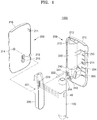
- FIG.1 is an exploded perspective view of a charging system according to an embodiment
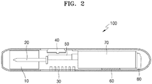
- FIG.2 is a cross-sectional view of an aerosol generating apparatus of FIG.1 .
- a charging system for an aerosol generating apparatus (hereinafter, referred to as "charging system") 1000 includes an aerosol generating apparatus 100 including a heater 20 that generates heat when an electric current is applied thereto, a power storage unit 70 supplying electric power to the heater 20, and a controller 50 for controlling the heater 20, and an external power supply device 200 including a case 210, a charging accommodation portion 220 provided to be rotatable in the case 210 to accommodate the aerosol generating apparatus 100 detachably, an auxiliary power storage device 230 storing power to be supplied to the aerosol generating apparatus 100, and an auxiliary power supply device 240 supplying the power to the aerosol generating apparatus 100 by controlling the auxiliary power storage device.
- an aerosol generating apparatus 100 including a heater 20 that generates heat when an electric current is applied thereto, a power storage unit 70 supplying electric power to the heater 20, and a controller 50 for controlling the heater 20, and an external power supply device 200 including a case 210, a charging accommodation portion 220 provided to be rota
- the aerosol generating apparatus 100 includes a first button portion 40 that may be pushed to pre-heat the aerosol generating apparatus 100, the heater 20 that generates heat due to resistance when an electric current is applied thereto, the power storage unit 70 capable of instantly supplying high power to the heater 20, and the controller 50 for controlling the heater 20.
- the heater 20 generates aerosol a vaporizing material including an aerosol generating material that vaporizes when being heated to a predetermined temperature or greater accommodated in a cartridge 10.
- the power storage unit 70 supplies the electric power to the heater 20 to heat the heater 20.
- a deactivation signal is transferred to the controller 50 to block the power supply from the power storage unit 70 to the heater 20.
- the heater 20 When an electronic tobacco of a cigarette type filled with paper impregnated or coated with an inhalation material is inserted to the cartridge 10, the heater 20 is heated to vaporize the inhalation material in a cigarette portion and the user may inhale the inhalation material that is vaporized through a filter portion.
- the controller 50 drives a motor 80 to vibrate the aerosol generating apparatus 100 so that the user may recognize it.
- the controller 50 displays a remaining power of the power storage unit 70 via a first display portion (not shown) provided in the aerosol generating apparatus 100, and even when the aerosol generating apparatus 100 is impossible to operate because the heater 20 lacks the electric power, the status of the power storage unit 70 may be displayed through the first display portion.
- the power storage unit 70 may be supplied with the electric power through the charging terminal 30 of the aerosol generating apparatus 100 via wires, wherein the charging terminal 30 is connected to the charging terminal 223 of the charging accommodation portion 220 in a state where the aerosol generating apparatus 100 is accommodated in the charging accommodation portion 220 of the external power supply device 200, and when the aerosol generating apparatus 100 receives the power supply, the controller 50 may display the electric power supplied to the power storage unit 70 through a second display portion (not shown).
- the aerosol generating apparatus 100 may perform data communication with the charging terminal 223 of the external power supply device 200 via the charging terminal 30. Also, the aerosol generating apparatus 100 may include an additional wireless communication port. The controller 50 guides communication between a wireless communication port in the aerosol generating apparatus 100 and a wireless communication port in the external power supply device 200 s as to perform data communication with the auxiliary power supply device 240, and then may receive the power supply wirelessly from the external power supply device 200.
- the power storage unit 70 may be separated from the aerosol generating apparatus 100, and the external power supply device 200 includes a plurality of accommodation portions for accommodating the power storage unit 70 so that one or more power storage devices 70 separated from the aerosol generating apparatus 100 may be accommodated and charged therein.
- the aerosol generating apparatus 100 may include a power-generation unit that converts external energy such as optical energy or mechanical energy into electrical energy to charge the power storage unit 70.
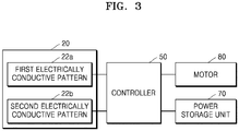
- FIG.3 is a block diagram of some of the components in the aerosol generating apparatus of FIG.1
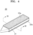
- FIG.4 is a perspective view showing some of the components in the aerosol generating apparatus of FIG.1
- FIG.5 is a cross-sectional view taken along line IV-IV of FIG.4 .
- the aerosol generating apparatus 100 includes a heater 20 that generates heat by the electricity and heats a vaporizing material to generate aerosol, wherein the vaporizing material includes an aerosol forming material that vaporizes when being heated to a predetermined temperature or greater, and the heater 20 includes a main body 21 in which a cigarette is inserted, a first electrically conductive pattern 22a provided on a portion of the main body 21 and functioning as one of a heater that heats the cigarette and a temperature sensor sensing a temperature of the cigarette, a second electrically conductive pattern 22b provided on another portion of the main body 21 and functioning as one of a heater and a temperature sensor, and a controller 50 controlling the first and second electrically conductive patterns 22a and 22b so that each of the first and second electrically conductive patterns 22a and 22b functions as one of the heater and the temperature sensor.
- the first electrically conductive pattern 22a and the second electrically conductive pattern 22b are respectively connected to an additional power supply unit
- the main body 21 may include, but is not limited to, a ceramic material.
- the main body 21 may include a material having non-conductive, thermal-resistant, and less deformable characteristics.
- the main body 21 may be formed to have an acute angle at an end portion that firstly contacts the cigarette when the cigarette is inserted, but one or more embodiments are not limited thereto.
- the main body 21 may be formed in any type provided that the cigarette is inserted into the main body 21.
- the first and second electrically conductive patterns 22a and 22b include an electrically resistant material.
- the electrically conductive track may include metal.
- the electrically conductive track may include an electrically conductive ceramic material, carbon, metal alloy, or a composite material of a ceramic material and metal.
- a cut surface of the main body 21 that is cut perpendicularly to a lengthwise direction of the cigarette may have a rectangular shape, but one or more embodiments of the disclosure are not limited thereto. That is, the cut surface of the main body 21 that is cut perpendicularly to the lengthwise direction of the cigarette may have a polygonal shape, a side of the cut surface may be a curve, or the cut surface may have a circular or an oval shape.
- a case in which the cut surface of the main body 21 cut perpendicularly to the lengthwise direction of the cigarette has a circular shape will be described below with reference to FIGS. 6 to 11 , and a case in which the cut surface of the main body 21 that is cut perpendicularly to the lengthwise direction of the cigarette has a rectangular shape will be described for convenience of description.
- the first electrically conductive pattern 22a is provided on a surface of the main body 21 and the second electrically conductive pattern 22b may be provided on another surface different from the above surface.
- the controller 50 controls the heater 20 so that the first electrically conductive pattern 22a functions as a heater and the second electrically conductive pattern 22b functions as a temperature sensor. That is, one of the first and second electrically conductive patterns 22a and 22b functions as a heater and the other functions as a temperature sensor. When the first electrically conductive pattern 22a functions as the temperature sensor, the second electrically conductive pattern 22b may function as the heater.
- the controller 50 may control the heater 20 so that the first and second electrically conductive patterns 22a and 22b may alternately function as the heater and the temperature sensor.
- the heater 20 requires instantly high voltage
- the controller 50 controls the first and second electrically conductive patterns 22a and 22b of the main body 21 to function as the heater 20 in order to instantly increase the temperature of the heater 20.
- the controller 50 controls the first and second electrically conductive patterns 22a and 22b of the main body 21 to function alternately as the heater and the temperature sensor.
- one or more of the first and second electrically conductive patterns 22a and 22b may function as the temperature sensor that senses temperature by measuring thermal resistance.
- FIG.6 is a perspective view showing some of the components in the aerosol generating apparatus of FIG.4 according to another embodiment, and FIG.7 is a cross-sectional view taken along line VI-VI of FIG.6 .
- an electronic heater 120 may include a main body 121 of a sewing needle shape, a first electrically conductive pattern 122a formed on a portion of an outer circumferential surface of the main body 121, and a second electrically conductive pattern 122b formed on another portion of the outer circumferential surface of the main body 121.
- the first and second electrically conductive patterns 122a and 122b may be respectively connected to an additional power supply unit such as the power storage unit 70.
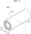
- FIG.8 is a perspective view showing some of the components in the aerosol generating apparatus of FIG.4 according to another embodiment
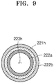
- FIG.9 is a cross-sectional view taken along line VII-VII of FIG.8 .
- an electronic heater 220h includes a main body 221h of a cylindrical shape having a hollow 223h therein, a first electrically conductive pattern 222a provided on an inner circumferential surface of the main body 221h, and a second electrically conductive pattern 222b provided on an outer circumferential surface of the main body 221h.
- the first and second electrically conductive patterns 222a and 222b are respectively connected to an additional power supply unit such as the power storage unit 70.
- the cigarette is inserted into the hollow 223h. That is, the first electrically conductive pattern 222a may be in contact with an outer circumferential surface of the cigarette.
- the controller 50 may control both the first electrically conductive pattern 222a contacting the cigarette and the second electrically conductive pattern 222b not contacting the cigarette to function as the heater in order to rapidly increase the temperature of the cigarette.
- the controller 50 may control the first electrically conductive pattern 222a contacting the cigarette to function as the heater and the second electrically conductive pattern 222b not contacting the cigarette to function as the temperature sensor. Also, in a vaporizing temperature maintaining stage, the controller 50 may control the second electrically conductive pattern 222b not contacting the cigarette to function as the heater and the first electrically conductive pattern 222a contacting the cigarette to function as the temperature sensor.
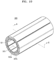
- FIG.10 is a perspective view showing some of the components in the aerosol generating apparatus of FIG.4 according to another embodiment
- FIG.11 is a cross-sectional view taken along line X-X of FIG.10 .
- an electronic heater 320 includes a main body 321 having a cylindrical shape partitioned as a plurality of pieces in a circumferential direction thereof, wherein the cylindrical shape has a hollow 323 therein, a first electrically conductive pattern 322a provided on an inner circumferential surface of each piece of the main body 321, and a second electrically conductive pattern 322b provided on an outer circumferential surface of each piece of the main body 321.
- a plurality of first electrically conductive patterns 322a and second electrically conductive patterns 322b are respectively connected to power supply units such as the power storage unit 70.
- the controller 50 controls the electronic heater 320 so that the first electrically conductive pattern 322a functions as a heater and the second electrically conductive pattern 322b functions as a temperature sensor.
- controller 50 controls the first electrically conductive pattern 322a and the second electrically conductive pattern 322b to alternately function as the heater and the sensor in order to increase lifespan of the electronic heater 320.
- the electronic heater 320 requires instantly high voltage, and the controller 50 controls the first and second electrically conductive patterns 322a and 322b to function as the electronic heater 320 in order to instantly increase the temperature of the electronic heater 320.
- the controller 50 may control the first electrically conductive pattern 322a contacting the cigarette to function as the heater and control the second electrically conductive pattern 322b not contacting the cigarette to function as the sensor in order to rapidly increase the temperature of the cigarette.
- the controller 50 may control the second electrically conductive pattern 322b not contacting the cigarette to function as the heater and the first electrically conductive pattern 322a contacting the cigarette to function as the sensor.
- FIG.12 is a block diagram showing some of components in the aerosol generating apparatus of FIG.1 .
- the aerosol generating apparatus 100 includes the heater 20 that generates heat due to resistance when electric current is applied thereto, the power storage unit 70 that supplies high electric power instantly to the heater 20, a vaporizing material sensor 90 sensing whether the vaporizing material is mounted, and the controller 50 controlling at least one of the above-stated elements.
- the heater 20 generates fine particles a vaporizing material including a material (vaporizing material) that vaporizes when being heated to a predetermined temperature or greater.
- the controller 50 controls the heater 20 in a pre-heating stage, a vaporizing temperature reaching stage, and a vaporizing temperature maintaining stage according to use of the aerosol generating apparatus 100.
- the controller 50 senses the vaporizing material via the vaporizing material sensor 90, controls the heater 20 to pre-heat the aerosol generating apparatus 100 and instantly increase the temperature to a desired vaporizing temperature, and then controls the heater 20 to maintain the vaporizing temperature for a predetermined time period.
- the controller 50 When the vaporizing material sensor 90 does not sense the vaporizing material in a state where the user pushes the first button portion 40 of the aerosol generating apparatus 100, the controller 50 operates the heater 20 only to the pre-heating stage in order to prevent unnecessary operations. In addition, when the vaporizing material sensor 90 does not sense the vaporizing material even after a predetermined time period elapses, the controller 50 controls the power storage unit 70 to block the power supplied to the heater 20 in order to prevent unnecessary power consumption.
- the aerosol generating apparatus 100 may include a touch sensor 91 for sensing a touch of the lips of the user. Therefore, the aerosol generating apparatus 100 may sense the touch of the lips, as well as the vaporizing material, and thus, the controller 50 may control the heater 20 of the aerosol generating apparatus 100.
- the controller 50 controls the heater 20 to pre-heat the aerosol generating apparatus 100 in a state where the user pushes the first button portion 40 of the aerosol generating apparatus 100 of FIG.2 , and then, when the touch of the lips of the user is sensed by the touch sensor 91, the controller 50 increases the temperature of the heater 20 to a target vaporizing temperature. Then, the controller 50 controls the heater to maintain the vaporizing temperature for a predetermined time period, so as to control the heater 20 in the pre-heating stage, the vaporizing temperature reaching stage, and the vaporizing temperature maintaining stage.
- the controller 50 controls the power storage unit 70 to block the power supplied to the heater 20 and prevent unnecessary power consumption.
- the controller 50 may determine whether the aerosol generating apparatus 100 is in an available status without being recharged, based on a remaining power amount regardless of whether the use of the aerosol generating apparatus 100 has occurred.
- the remaining power amount denotes a state in which the aerosol generating apparatus 100 may not operate unless it is recharged
- the aerosol generating apparatus 100 may receive the power from the external power supply device 200 through an external power supplier 92 that allows the external power to be supplied. Therefore, termination of using the aerosol generating apparatus 100 because the power storage unit 70 runs out of the power while the user uses the aerosol generating apparatus 100 may be prevented.
- electronic circuits connected from the power storage unit 70 to the heater 20 may be at least partially formed of a single-crystalline material.
- a single-crystalline material has regular arrangement of atoms, ions, and molecules in a solid, and the single-crystalline material has a structure in which atoms are regularly and completely arranged therein. Even one kind of solid may have a single-crystalline structure or poly-crystalline structure according to arrangement status of atoms, ions, and molecules in the solid.
- a single-crystalline material has characteristics of low frequency dependence, low resistivity, high surface stability (hardly oxidized-antioxidation characteristic), no grain boundary scattering, and high adhesion.
- heat generation amount of wires may be reduced when the wires of the electronic circuit include a solid material of a single-crystalline structure, a temperature of a resistive heater connected to the electronic circuit may be rapidly increased.
- the heater 20 heats the cigarette accommodated in the cartridge 10 to a predetermined temperature or greater to generate fine particles.
- the aerosol generating apparatus instantly supplies high power to the heater 20 from the power storage unit 70 to rapidly increase the temperature of the heater 20.
- the temperature of the heater 20 needs to be rapidly increased within 1, 2, 3, or 4 sec. after starting the operation of the aerosol generating apparatus, so that the cigarette accommodated in the cartridge 10 is heated at a temperature range of 200 ⁇ C to 400 ⁇ C.
- the electronic circuit connecting the power storage unit 70 to the heater 20 may at least partially include a single-crystalline material.
- the heat generation amount of the wire may be reduced due to the low resistivity of the single-crystalline material, and thus, the temperature of the heater 20 connected to the electronic circuit may be rapidly increased to a desired temperature. That is, since the wires included in the electronic circuit include the single-crystalline material having low resistivity and the temperature of the heater 20 may be rapidly increased to heat the cigarette at the preset temperature range, power efficiency of the fine particle generator may be improved.
- the single-crystalline material may be grown from any one of the group consisting of gold, copper, silver, aluminum, and nickel.
- the single-crystalline material may include single-crystalline copper (Cu).
- the single-crystalline material is not limited to the above examples.
- the single-crystalline material may be formed from at least one of an ingot form and a thin film form.
- a single-crystalline material grown as an ingot is cut into plate-shaped pieces, and the wires of the electronic circuit may be formed by using the plate-shaped pieces.
- FIG.13 is a cross-sectional view showing a detailed configuration of a heater in the aerosol generating apparatus of FIG.12 .
- a heater 420 for a rod-type electrical heating smoking device includes a ceramic rod 421 having a cutting-edge, a first protective layer 422 surrounding the ceramic rod 421, a green sheet 423 wound on the first protective layer 422 and having electrode patterns 423a and 423b including an electrode pattern of the heater 420 printed thereon, a second protective layer 424 surrounding the green sheet 423, a glass film protective coating layer 425 formed on a coupling body covered with the second protective layer 424, a flange 426 coupled to a coupling body on which the glass film protective coating layer 425, and an anti-fouling coating layer 427 formed on an outermost layer.
- the ceramic rod 421 is processed to have an appropriate length and diameter to provide the heater with a rigidity for inserting into the cigarette.
- the first protective layer 422 is formed on an outer circumference of the ceramic rod 421 in order to increase attachability of the green sheet 423, on which resistor is printed, and to prevent cracks from occurring in the ceramic rod 421.
- the first protective layer 422 may be formed by attaching a protective film or performing a glass film coating.
- the green sheet 423 on which the resistor is printed is attached to the first protective layer 422.
- the electrode patterns 423a and 423b are printed on opposite surfaces of the green sheet 423, that is, a heater electrode pattern 423a is printed on an internal surface and a sensor electrode pattern 423b is printed on an external surface.
- the electrode patterns 423a and 423b of the green sheet 423 are printed by a silk screen method or an inkjet printing method.
- FIG.14 is a conceptual diagram illustrating a method of manufacturing a green sheet with a resistor printed on opposite surfaces thereof included in the heater of FIG.13 .
- a ceramic green sheet is manufactured and cut, and then, the heater electrode pattern 423a is printed on a surface and the sensor electrode pattern 423b is printed on the other surface.
- the green sheet 423 with the electrode patterns printed on opposite surfaces thereof is wound on an external portion of the first protective layer 422 on the ceramic rod 421.
- the electrode patterns 423a and 423b may include one or more selected from Ni, Pt, W, Mo, W-Mo alloy, Nichrome alloy, Kanthal alloy, and stainless steel.
- an electrode material included in the sensor electrode pattern 423b may have a temperature coefficient of resistance that is higher than that of an electrode material included in the heater electrode pattern 423a.
- the second protective layer 424 is formed on an outer side of the green sheet 423 in order to protect the electrode pattern 423b printed on the green sheet 423.
- the second protective layer 424 may be also formed by performing a glass film coating or winding a protective film.
- the green sheet 423, and the second protective layer 424 sequentially on the ceramic rod 421, the green sheet 423 and the electrode patterns 423a and 423b are sintered. After that, a primary appearance test and a resistance check of the electrode patterns 423a and 423b are performed.
- a body obtained by attaching the first protective layer 422, the green sheet 423, and the second protective layer 424 sequentially on the ceramic rod 421 and sintering the green sheet 423 and the electrode patterns 423a and 423b is referred to as a ceramic rod assembly.
- FIG.15 is a cross-sectional view of a ceramic rod assembly included in the heater of FIG.13 .
- a ceramic rod assembly 150 may have a stair shape at a side of the cutting-edge of the ceramic rod because upper layers have reduced lengths, so that the heater may be easily inserted into the cigarette.
- the flange 426 for easily installing the heater is coupled to the ceramic rod assembly 150.
- the glass film protective coating layer 425 may be covered on the ceramic rod assembly 150 so that the stair-shape on the outer appearance of the ceramic rod assembly 150 may have smooth surface.
- the glass film protective coating layer 425 covers exposed cutting-edge of the ceramic rod 421, a part of the first protective layer 422 at the cutting-edge side, a part of the green sheet 423 at the cutting-edge side, and entire second protective layer 424.
- the glass film protective coating layer 425 allows the heater to be smoothly inserted to the cigarette, and may prevent isolation of layers, that is, a plurality of thin films or coating layers, of the heater.
- the anti-fouling coating layer 427 may be further formed on an outermost portion of the ceramic rod 421, that is, on an outer portion of the glass film protective coating layer 425.
- a material for forming the anti-fouling coating layer 427 may include nano-ceramic particles such as SiO 2 , Si 3 N 4 , and BN.
- the electrode patterns 423a and 423b of the green sheet 423 include soldering pads (not shown) for connecting to bridge wires 510, 520, and 530 that are provided to apply external power.
- the soldering pad may be located at an end of the green sheet 423 so as to be easily connected to the bridge wires 510, 520, and 530, and the end of the green sheet 423 is not the side of the cutting-edge of the ceramic rod 421, but an opposite end of the cutting-edge, that is, a lower end (right side on the drawing).
- the flange 426 is located above the soldering pad of the green sheet 423 when being coupled to the ceramic rod assembly 150, and thus the soldering pad (not shown) and the bridge wires 510, 520, and 530 are blocked by the flange 426 not to be inserted to the cigarette when the heater is inserted into the cigarette.
- FIG.16 is a conceptual diagram showing two bridge wires connected to the heater of FIG.13 .
- two bridge wires 510' and 520' are connected to the heater in a case where the electrode patterns 423a and 423b formed on the green sheet 423 only include heater patterns.
- the bridge wires 510' and 520' are respectively connected to a (+) pole and a (-) pole of the power source.
- FIG.17 is a conceptual diagram showing three bridge wires connected to the heater of FIG. 13 .
- three bridge wires 510', 520', and 530 are connected to the heater when the electrode patterns 423a and 423b (see FIG.4 ) formed on the green sheet 423 (see FIG.4 ) include the heater electrode pattern 423a (see FIG.4 ) and the sensor electrode pattern 423b (see FIG.4 ).
- the three bridge wires 510', 520', and 530 are respectively connected to the heater electrode pattern 423b (see FIG.4 ), the sensor electrode pattern 423b, and a ground.
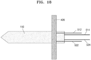
- FIG. 18 is a conceptual diagram showing four bridge wires connected to the heater of FIG. 13 .
- four bridge wires 512, 514, 522, and 524 are connected to the heater when the electrode patterns 423a and 423b (see FIG.4 ) formed on the green sheet 423 (see FIG.4 ) include the heater electrode pattern 423a (see FIG.4 ) and the sensor electrode pattern 423b (see FIG.4 ).
- the four bridge wires 512, 514, 522, and 524 respectively include the bridge wires 512 and 514 of (+) and (-) poles connected to the heater electrode pattern 423a (see FIG.4 ) and the bridge wires 522 and 524 of (+) and (-) poles connected to the sensor electrode patterns 423b (see FIG.4 ).
- the bridge wires 510', 520', 530, 512, 514, 522, and 524 may include one or more selected from Ni, Pt, W, Al, Ag, Au, Kanthal-based alloy, and stainless steel.
- FIG.19 is a conceptual diagram of a first operating example of a charging system of FIG.1 .
- the external power supply device 200 include cases 210 that may be separated from each other, and each of the cases 210 have a partitioned inside so that elements of the external power supply device 200 may be mounted, and also include a plurality of hooks 211 and hook recesses 212 to be coupled to each other.
- the charging accommodation portion 220 is installed to be rotatable in the case 210 and accommodates the aerosol generating apparatus 100 to be detachable.
- the charging accommodation portion 220 include a hinge 222 via a hole 221 formed in each side surface and insert the hinge 222 to a concave recess 214 formed in the case 210 to be installed rotatably with respect to the case 210.
- a side of the charging accommodation portion 220 which faces the aerosol generating apparatus 100, may have a shape corresponding to an outer appearance of the aerosol generating apparatus 100 in order to stably accommodate the aerosol generating apparatus 100.
- the auxiliary power storage device 230 and the auxiliary power supply device 240 are connected via wires, and the auxiliary power supply device 240 is connected to a charging terminal 223 formed in the charging accommodation portion 220 via a wire 224.
- the auxiliary power storage device 230 stores power to be transferred to the aerosol generating apparatus 100, and the auxiliary power supply device 240 controls the auxiliary power storage device 230 to supply the power to the aerosol generating apparatus 100.
- the auxiliary power storage device 230 and the auxiliary power supply device 240 may be mounted in an accommodation portion 213 of the external power supply device 200.
- the auxiliary power supply device 240 controls the auxiliary power storage device 230 to be charged by a general external power source built in a case such as a universal serial bus (USB) port 242, and displays a charging status of the auxiliary power storage device 230 through a light-emitting diode (LED) 241.
- a general external power source built in a case such as a universal serial bus (USB) port 242
- USB universal serial bus
- LED light-emitting diode
- the LED 241 includes three LEDs so as to turn on one LED, two or three LEDs according to the charged amount, and when the three LEDs are turned on, the auxiliary power storage device 230 is at the maximum charging status.
- Each LED in the LED 241 may be turned on to outside of the case through a hole 215 provided in the case 210 that is coupled to the case 210 in which the LED 241 is mounted.
- the case 210 includes a second button portion 243 protruding out of the case 210 through a hole 215, and the second button portion 243 is supported by a fixing protrusion 244 in the case 210.
- the second button portion 243 is connected to the auxiliary power supply device 240 via wires.
- an activation signal is transferred to the auxiliary power supply device 240 to allow the auxiliary power storage device 230 to supply the power to the aerosol generating apparatus 100, and when the user manipulates the second button portion 243 again while the auxiliary power storage device 230 supplies the power to the aerosol generating apparatus 100, the power supply from the auxiliary power storage device 230 to the aerosol generating apparatus 100 may be blocked.
- the auxiliary power supply device 240 allows the auxiliary power storage device 230 to allow the power to the aerosol generating apparatus 100 to operate the aerosol generating apparatus 100 in a cleaning mode, in which the aerosol generating apparatus 100 is cleaned by melting ash or impurities on the aerosol generating apparatus 100.
- a signal of manipulating the second button portion 243 by the user is transferred from the auxiliary power supply device 240 to the controller 50 of the aerosol generating apparatus 100 via the charging terminal 223 of the charging accommodation portion 220 and the charging terminal 30 of the aerosol generating apparatus 100, and operates the heater 20 of the aerosol generating apparatus 100.
- the heater 20 of the aerosol generating apparatus 100 may be operated by manipulating the second button portion 243 of the external power supply device 200 in a state where the aerosol generating apparatus 100 is mounted in the charging accommodation portion 220 and the charging accommodation portion 220 is located in parallel with the lengthwise direction of the case 210.
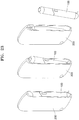
- FIG.20 is a conceptual diagram showing a second operating example of the charging system of FIG.1
- FIG.21 is a conceptual diagram showing a third operating example of the charging system of FIG.1 .
- the auxiliary power supply device 240 allows the auxiliary power storage device 230 to allow the power to the aerosol generating apparatus 100 to operate the aerosol generating apparatus 100 in a pre-heating mode, in which the aerosol generating apparatus 100 is pre-heated.
- the charging terminal 223 of the charging accommodation portion 220 is connected to the charging terminal 30 of the aerosol generating apparatus 100 to face the charging terminal 223, in a state where the aerosol generating apparatus 100 is accommodated in the charging accommodation portion 220, and the power charged in the auxiliary power storage device 230 may be supplied to the aerosol generating apparatus 100 according to control of the auxiliary power supply device 240.
- the auxiliary power supply device 240 includes a wireless communication port so as to supply the power wirelessly to the aerosol generating apparatus 100, as well as through wires.
- the power supply from the auxiliary power storage device 230 to the aerosol generating apparatus 100 is allowed and the heater 20 of the aerosol generating apparatus 100 may be heated.
- a deactivation signal is transferred to the auxiliary power supply device 240 and the power supply from the auxiliary power storage device 230 to the aerosol generating apparatus 100 may be blocked.
- the case 210 includes a first magnetic body 250 and a second magnetic body 260 that are arranged to be symmetric with each other about a rotating center, that is, the hinge 222.
- the charging accommodation portion 220 include a third magnetic body 225 facing one of the first magnetic body 250 and the second magnetic body 260.
- the third magnetic body 225 faces the first magnetic body 250, but one or more embodiments are not limited thereto, that is, the third magnetic body 225 may be provided at a lower end of the charging accommodation portion 220 to face the second magnetic body 260.
- the third magnetic body 225 is provided at an upper end of the charging accommodation portion 220 to face the first magnetic body 250 will be described below.
- one of the first magnetic body 250 and the second magnetic body 260 may be installed on the case 210 to be inclined with respect to the lengthwise direction of the case 210.
- the second magnetic body 260 that is provided at the lower side of the external power supply device 200 is installed on the case 210 to be inclined with respect to the lengthwise direction of the case 210, but one or more embodiments are not limited thereto, that is, the first magnetic body 250 may be installed on the case 210 to be inclined with the lengthwise direction of the case 210.
- the second magnetic body 260 is inclined with respect to the lengthwise direction of the case 210 will be described below.
- the aerosol generating apparatus 100 may include a fourth magnetic body 60 that faces one of the first magnetic body 250 and the second magnetic body 260, which does not face the third magnetic body 225.
- the first magnetic body 250 and the second magnetic body 260 are provided respectively on the upper and lower ends of the case 210 of the external power supply device 200, the third magnetic body 225 facing the first magnetic body 250 may be provided on the upper end of the charging accommodation portion 220 and the fourth magnetic body 60 facing the second magnetic body 260 may be provided on the lower end of the aerosol generating apparatus 100.
- a magnetic force may be applied between the first magnetic body 250 and the third magnetic body 225, between the first magnetic body 250 and the fourth magnetic body 60, between the second magnetic body 260 and the third magnetic body 225, and between the second magnetic body 260 and the fourth magnetic body 60.
- the charging accommodation portion 220 may be arranged in parallel with the lengthwise direction of the case 210 as shown in FIG.3 due to the magnetic force between the first magnetic body 250 and the third magnetic body 225.
- the charging accommodation portion 220 rotates in a clockwise direction as shown in FIG. 11 and the charging accommodation portion 220 may be arranged in a direction crossing the lengthwise direction of the case 210 due to the magnetic force generated between the third magnetic body 225 and the fourth magnetic body 60.
- the aerosol generating apparatus 100 may tilt to correspond to the inclination angle of the second magnetic body 260 within the external power supply device 200.
- the user presses the tilted aerosol generating apparatus 100 with a power that is greater than the magnetic force between the second magnetic body 260 and the fourth magnetic body 60, and then, the aerosol generating apparatus 100 may be separated from the external power supply device 200 as shown in FIG.12 .
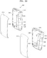
- FIG.22 is an exploded perspective view showing a status in which the aerosol generating apparatus of FIG.1 is available in a state of being accommodated in an external power supply device.
- the aerosol generating apparatus 100 may receive the power supply while being mounted in the charging accommodation portion 220 of the external power supply device 200.
- the lower end of the aerosol generating apparatus 100 is pushed in a state where the aerosol generating apparatus 100 is accommodated in the charging accommodation portion 220 of the external power supply device 200 by the fourth magnetic body 60, and then, the charging accommodation portion 220 is adhered to the second magnetic body 260 inclined at a predetermined angle in the case 210 due to the fourth magnetic body 60 included in the aerosol generating apparatus 100 in a state where the aerosol generating apparatus 100 is accommodated in the charging accommodation portion 220.
- an upper portion of the aerosol generating apparatus 100 is partially exposed to outside in a state where the aerosol generating apparatus 100 is inclined a predetermined angle to the outer portion of the case 210, and the user inserts the cigarette into the cartridge 10 of the aerosol generating apparatus 100, which is exposed outside, and pushes the second button portion 243 of the external power supply device 200 to pre-heat the aerosol generating apparatus 100.
- the aerosol generating apparatus 100 may be continuously used while receiving the electric power from the charging system 1000.
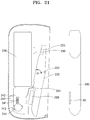
- FIG.23 is a perspective view showing a process of separating the aerosol generating apparatus of FIG.1 from the external power supply device.
- the user presses the aerosol generating apparatus 100 in a state where the aerosol generating apparatus 100 is inclined and partially exposed from the external power supply device 200 to withdraw the aerosol generating apparatus 100 overcoming the magnetic force between the aerosol generating apparatus 100 and the external power supply device 200.
- ... unit may be realized by a hardware component such as a processor or a circuit, and/or a software component executed via a hardware component such as a processor.
- the aerosol generating apparatus capable of vaporizing an aerosol generating material without being accompanied by combustion may be implemented. It follows a list of examples:
Abstract
Description
- One or more embodiments relate to an aerosol generating apparatus including various power supply units, a method of controlling the aerosol generating apparatus, and a charging system including the aerosol generating apparatus.
- Inhalation of a favored material, for example, tobacco smoke, may be achieved by inhaling fine particles in the air, that is, aerosol. Conventionally, cigarette-type tobacco has been the only favored material for inhalation, but recently, an electronic cigarette has been established as a way of inhaling the favored material. An electronic cigarette is totally different from a conventional cigarette that generates smoke by burning an inhalation material in view of a method, because the electronic cigarette generates aerosol by applying heat or ultrasonic waves to a cartridge, in which an inhalation material is contained in a liquid form, to vaporize the inhalation material. In addition, an electronic cigarette has advantages of preventing various harmful materials from being generated due to combustion.
- Also, according to demand of consumers who prefer a general cigarette-type tobacco, an electronic cigarette having a form including a filter portion and a cigarette portion like a general cigarette has been suggested, and the electronic cigarette is configured so that a user may inhale the inhalation material through the filter portion that is similar to that in the general cigarette, wherein the inhalation material included in the cigarette portion is vaporized by using an electronic heater. In such an electronic cigarette as above, the cigarette portion is filled with paper that is impregnated or coated with the inhalation material, unlike in a general cigarette having the cigarette portion filled with dried tobacco leaves. When the electronic cigarette is inserted into a holder and a heater in the holder is heated to vaporize the inhalation material in the cigarette portion, the user may inhale the vaporized inhalation material through the filter portion. Since the vaporized inhalation material may be inhaled through the filter portion in the same way as in the traditional cigarette while having the advantage of not burning the tobacco like in the electronic cigarette according to the related art, the user may feel like he/she is smoking the traditional cigarette.
- An electronic cigarette may be reused after separating and recharging a charger in the electronic cigarette by using an additional charger after use for a predetermined time period. In general, when an electronic cigarette is used for one day or two, a battery thereof is discharged and has to be recharged, and a user may feel inconvenience because the electronic cigarette may turn off while being used. Also, although a capacity of a battery may be increased to increase a usable time of the electronic cigarette, a size of the battery increases and a weight and an outer appearance of the electronic cigarette becomes greater. Also, there is an electronic cigarette having a battery that is replaceable, but a user has to carry the battery always. In addition, it is inconvenient to use the electronic cigarette because the battery has to be separated and charged, and there is a concern about losing the battery.
- One or more embodiments of the disclosure provide an aerosol generating apparatus using a variety of inhalation materials without being accompanied by combustion, a method of controlling the aerosol generating apparatus, and a charging system including the aerosol generating apparatus.
- Also, one or more embodiments provide an aerosol generating apparatus allowing a user to successively smoke without interrupting the smoking of the user, a method of controlling the aerosol generating apparatus, and a charging system including the aerosol generating apparatus.
- Also, one or more embodiments provide an aerosol generating apparatus including a heater and/or a temperature sensor having a reduced number of components and being provided with various designs, and an aerosol generating method.
- Also, one or more embodiments provide an aerosol generating apparatus that may supply power simply through a detachable type power storage device or an additional auxiliary power storage device and is portable and easy to use, a method of controlling the aerosol generating apparatus, and a charging system including the aerosol generating apparatus.
- According to an aspect of the disclosure, an aerosol generating apparatus includes: a main body in which a cigarette is inserted; a first electrically conductive pattern provided on a portion of the main body to function as one of a heater for heating the cigarette and a temperature sensor sensing a temperature of the cigarette; a second electrically conductive pattern provided on another portion of the main body to function as one of the heater and the temperature sensor; and a controller controlling the first electrically conductive pattern and the second electrically conductive pattern to make the first electrically conductive pattern and the second electrically conductive pattern function as one of the heater and the temperature sensor.
- According to one or more embodiments of the disclosure, there are provided an aerosol generating apparatus capable of vaporizing an aerosol forming material without being accompanied by combustion, a method of controlling the aerosol generating apparatus, and a charging system including the aerosol generating apparatus.
- Also, provided are an aerosol generating apparatus including a plurality of conductive patterns at different locations of a main body to use the conductive patterns a heater or a temperature sensor and reduce the number of components, and including the heater and the temperature sensor of various types, a method of controlling the aerosol generating apparatus, and a charging system including the aerosol generating apparatus.
- Also, provided are an aerosol generating apparatus capable of uniformly heating a cigarette inserted into the aerosol generating apparatus, in which residue of the cigarette may not remain in the heater after smoking and the heater may not easily break, a method of controlling the aerosol generating apparatus, and a charging system including the aerosol generating apparatus.
- Also, provided are an aerosol generating apparatus capable of preventing unintentional operation stop because power may be supplied in various ways, a method of controlling the aerosol generating apparatus, and a charging system including the aerosol generating apparatus.
-
-
FIG.1 is an exploded perspective view of a charging system according to an embodiment; -
FIG.2 is a cross-sectional view of an aerosol generating apparatus ofFIG.1 ; -
FIG.3 is a block diagram showing some of components in the aerosol generating apparatus ofFIG.1 ; -
FIG.4 is a perspective view showing some of the components in the aerosol generating apparatus ofFIG. 1 ; -
FIG.5 is a cross-sectional view taken along a line IV-IV ofFIG.4 ; -
FIG.6 is a perspective view showing some of components in the aerosol generating apparatus ofFIG.4 according to another embodiment; -
FIG.7 is a cross-sectional view taken along a line VI-VI ofFIG.6 ; -
FIG.8 is a perspective view showing some of components in the aerosol generating apparatus of -
FIG.4 according to another embodiment; -
FIG.9 is a cross-sectional view taken along a line VII-VII ofFIG.8 ; -
FIG.10 is a perspective view showing some of components in the aerosol generating apparatus ofFIG.4 according to another embodiment; -
FIG.11 is a cross-sectional view taken along a line VI-VI ofFIG. 10 ; -
FIG. 12 is a block diagram showing some of components in the aerosol generating apparatus ofFIG.1 ; -
FIG.13 is a cross-sectional view showing a detailed configuration of a heater in the aerosol generating apparatus ofFIG.12 ; -
FIG.14 is a conceptual diagram illustrating a method of manufacturing a resistive double-printed green sheet included in the heater ofFIG.13 ; -
FIG.15 is a cross-sectional view of a ceramic rod assembly included in the heater ofFIG.13 ; -
FIG.16 is a conceptual diagram showing two bridge wires connected to the heater ofFIG.13 ; -
FIG.17 is a conceptual diagram showing three bridge wires connected to the heater ofFIG.13 ; -
FIG.18 is a conceptual diagram showing four bridge wires connected to the heater ofFIG.13 ; -
FIG.19 is a conceptual diagram of a first operating example of a charging system ofFIG.1 ; -
FIG.20 is a conceptual diagram of a second operating example of the charging system ofFIG.1 ; -
FIG.21 is a conceptual diagram of a third operating example of the charging system ofFIG.1 ; -
FIG.22 is an exploded perspective view showing a status in which the aerosol generating apparatus ofFIG.1 is available in a state of being accommodated in an external power supply device; and -
FIG.23 is a perspective view showing a process of separating the aerosol generating apparatus ofFIG.1 from the external power supply device. - According to an embodiment of the disclosure, an aerosol generating apparatus includes: a main body in which a cigarette is inserted; a first electrically conductive pattern provided on a portion of the main body to function as one of a heater for heating the cigarette and a temperature sensor sensing a temperature of the cigarette; a second electrically conductive pattern provided on another portion of the main body to function as one of the heater and the temperature sensor; and a controller controlling the first electrically conductive pattern and the second electrically conductive pattern to make the first electrically conductive pattern and the second electrically conductive pattern function as one of the heater and the temperature sensor.
- In the embodiment, the first electrically conductive pattern may function as a heater and the second electrically conductive pattern may function as a temperature sensor.
- In the embodiment, the first electrically conductive pattern and the second electrically conductive pattern may alternately function as one of the heater and the temperature sensor.
- In the embodiment, the first electrically conductive and the second electrically conductive pattern may function as the heater.
- In the embodiment, the controller may sense a temperature by measuring a thermal resistance of one or more of the first electrically conductive pattern and the second electrically conductive pattern.
- In the embodiment, the main body may have a cylindrical structure having a hollow therein, the first electrically conductive pattern may be provided on an inner circumferential surface of the main body, and the second electrically conductive pattern may be provided on an outer circumferential surface of the main body.
- In the embodiment, the main body may be obtained by partitioning a cylinder having a hollow into two or more pieces in a circumferential direction, the first electrically conductive pattern may be provided on an inner circumferential surface of each piece and the second electrically conductive pattern may be provided on an outer circumferential surface of each piece.
- According to another embodiment, a method of controlling an aerosol generating apparatus includes: instantly raising a temperature of a cigarette by using a first electrically conductive pattern and a second electrically conductive pattern as heaters for heating the cigarette; and heating the cigarette to a target temperature by using one of the first electrically conductive pattern and the second electrically conductive pattern as the heater and the other of the first electrically conductive pattern and the second electrically conductive pattern as a temperature sensor for measuring the temperature of the cigarette.
- In the embodiment, when the first electrically conductive pattern is closer to the cigarette than the second electrically conductive pattern, in the heating of the cigarette to the target temperature, the first electrically conductive pattern may be used as the heater and the second electrically conductive pattern may be used as the temperature sensor.
- In the embodiment, when the temperature of the cigarette reaches the target temperature, the temperature of the cigarette may be maintained by using the first electrically conductive pattern as the temperature sensor and using the second electrically conductive pattern as the heater.
- According to another embodiment of the disclosure, a charging system for an aerosol generating apparatus includes: an aerosol generating apparatus including a heater generating heat due to resistance when an electric current is applied thereto, a power storage unit supplying power to the heater, and a controller controlling the heater; and an external power supply device including a case, a charging accommodation portion provided rotatably on the case to accommodate the aerosol generating apparatus to be detachable, an auxiliary power storage device storing power that is to be transferred to the aerosol generating apparatus, and an auxiliary power supply device controlling the auxiliary power storage device to supply the power to the aerosol generating apparatus.
- In the embodiment, when the charging accommodation portion is in parallel with a lengthwise direction of the case, in a state where the aerosol generating apparatus is attached to the charging accommodation portion, the auxiliary power supply device may allow the auxiliary power storage device to supply power to the aerosol generating apparatus and the aerosol generating apparatus to operate in a cleaning mode, in which the aerosol generating apparatus is cleaned.
- In the embodiment, when the charging accommodation portion is in parallel with a lengthwise direction of the case, in a state where the aerosol generating apparatus is attached to the charging accommodation portion, the auxiliary power supply device may allow the auxiliary power storage device to supply power to the aerosol generating apparatus and the aerosol generating apparatus to operate in a pre-heating mode, in which the aerosol generating apparatus is pre-heated.
- In the embodiment, the aerosol generating apparatus may further include a first button portion that transfers an activation signal to the controller through a manipulation of a user to allow the power storage unit to supply power to the heater, and transfers a deactivation signal to the controller through a manipulation of the user while the power is supplied from the power storage unit to the heater to block the power supply from the power storage unit to the heater.
- In the embodiment, the external power supply device may further include a second button portion that transfers an activation signal to the auxiliary power supply device through a manipulation of the user to allow the auxiliary power storage device to supply power to the aerosol generating apparatus, and transfers a deactivation signal to the auxiliary power supply device through a manipulation of the user while the power is supplied from the auxiliary power storage device to the aerosol generating apparatus to block the power supply from the auxiliary power storage device to the aerosol generating apparatus.
- In the embodiment, the charging system may further include a first magnetic body and a second magnetic body provided on a case to face each other about a rotating center of the charging accommodation portion, and the charging accommodation portion may include a third magnetic body facing one of the first magnetic body and the second magnetic body.
- In the embodiment, one of the first and second magnetic bodies may be provided on the case to be inclined with respect to a lengthwise direction of the case.
- In the embodiment, the aerosol generating apparatus may include a fourth magnetic body facing the other of the first and second magnetic bodies.
- In the embodiment, a magnetic force may be applied between the first magnetic body and the third magnetic body, between the first magnetic body and the fourth magnetic body, between the second magnetic body and the third magnetic body, and between the second magnetic body and the fourth magnetic body.
- In the embodiment, the external power supply device may further include an accommodation portion for accommodating the auxiliary power storage device and the auxiliary power supply device.
- In the embodiment, the charging system may further include an electronic circuit connecting the auxiliary power storage device to the heater, the heater generates heat by receiving electric power from the auxiliary power storage device, and the electronic circuit may at least partially include a single-crystalline material.
- In the embodiment, the aerosol generating apparatus may further include a cartridge for accommodating the cigarette, and the cigarette accommodated in the cartridge may be heated within a preset temperature range by rapidly raising the temperature of the heater connected to the electronic circuit.
- In the embodiment, wires included in the electronic circuit may at least partially include a single-crystalline material.
- In the embodiment, the single-crystalline material may be formed from at least one of an ingot form and a thin film form.
- In the embodiment, the single-crystalline material may include single-crystalline copper (Cu).
- In the embodiment, the heater may include a ceramic rod having a cutting-edge, a first protective layer surrounding the ceramic rod, a green sheet wound on the first protective layer and having electrode patterns including a heater electrode pattern printed thereon, and a second protective layer surrounding the green sheet.
- In the embodiment, the electrode patterns of the green sheet may be printed by a silk screen method or an inkjet printing method.
- In the embodiment, the electrode patterns may be printed on both sides of the green sheet.
- In the embodiment, the electrode pattern on one of the both sides may include a sensor electrode pattern.
- In the embodiment, the charging system may further include a flange coupled to the ceramic rod surrounded by the green sheet and the first protective layer and bridge wires connected to the printed electrode patterns of the green sheet, and the bridge wires may be three-wire type or four-wire type.
- Other aspects, features and advantages of the disclosure will become better understood through the accompanying drawings, the claims and the detailed description.
- As the present disclosure allows for various changes and numerous embodiments, particular embodiments will be illustrated in the drawings and described in detail in the written description. The attached drawings for illustrating one or more embodiments are referred to in order to gain a sufficient understanding, the merits thereof, and the objectives accomplished by the implementation. However, the embodiments may have different forms and should not be construed as being limited to the descriptions set forth herein. That is, things that one of ordinary skill in the art may easily infer from the following detailed description and examples are interpreted to fall within the scope of the disclosure.
- The terms "consist(s) of " or "include(s) (or comprise(s))" should not be interpreted or understood as including, without exception, all of the plurality of elements or the plurality of steps disclosed in the description. In other words, it should be understood that some of the elements or some of the steps may not be included, or that additional elements or steps may be further included.
- While such terms as "first," "second," etc., may be used to describe various components, such components are not be limited to the above terms. The above terms are used only to distinguish one component from another. An expression used in the singular encompasses the expression of the plural, unless it has a clearly different meaning in the context.
- All terms including descriptive or technical terms which are used herein should be construed as having meanings that are obvious to one of ordinary skill in the art. However, the terms may have different meanings according to an intention of one of ordinary skill in the art, precedent cases, or the appearance of new technologies. Also, some terms may be arbitrarily selected by the applicant. In this case, the meaning of the selected terms will be described in the detailed description. Thus, the terms used herein have to be defined based on the meaning of the terms together with the description throughout the specification.
- Sizes of components in the drawings may be exaggerated for convenience of explanation. In other words, since sizes and thicknesses of components in the drawings are arbitrarily illustrated for convenience of explanation, the following embodiments are not limited thereto.
- One or more embodiments are related to an aerosol generating apparatus, and detailed descriptions about known matters to those of ordinary skill in the art will be omitted.
- The example embodiments will be described below in more detail with reference to the accompanying drawings. Those components that are the same or are in correspondence are rendered the same reference numeral regardless of the figure number, and redundant explanations are omitted.
-
FIG.1 is an exploded perspective view of a charging system according to an embodiment, andFIG.2 is a cross-sectional view of an aerosol generating apparatus ofFIG.1 . - Referring to
FIG.1 andFIG.2 , a charging system for an aerosol generating apparatus (hereinafter, referred to as "charging system") 1000 includes anaerosol generating apparatus 100 including aheater 20 that generates heat when an electric current is applied thereto, apower storage unit 70 supplying electric power to theheater 20, and acontroller 50 for controlling theheater 20, and an externalpower supply device 200 including acase 210, a chargingaccommodation portion 220 provided to be rotatable in thecase 210 to accommodate theaerosol generating apparatus 100 detachably, an auxiliarypower storage device 230 storing power to be supplied to theaerosol generating apparatus 100, and an auxiliarypower supply device 240 supplying the power to theaerosol generating apparatus 100 by controlling the auxiliary power storage device. - Referring to
FIG.2 , theaerosol generating apparatus 100 includes afirst button portion 40 that may be pushed to pre-heat theaerosol generating apparatus 100, theheater 20 that generates heat due to resistance when an electric current is applied thereto, thepower storage unit 70 capable of instantly supplying high power to theheater 20, and thecontroller 50 for controlling theheater 20. Theheater 20 generates aerosol a vaporizing material including an aerosol generating material that vaporizes when being heated to a predetermined temperature or greater accommodated in acartridge 10. - For example, when a user manipulates the
first button portion 40 to transfer an activation signal to thecontroller 50, thepower storage unit 70 supplies the electric power to theheater 20 to heat theheater 20. On the contrary, when the user manipulates thefirst button portion 40 while theheater 20 is heated, a deactivation signal is transferred to thecontroller 50 to block the power supply from thepower storage unit 70 to theheater 20. - When an electronic tobacco of a cigarette type filled with paper impregnated or coated with an inhalation material is inserted to the
cartridge 10, theheater 20 is heated to vaporize the inhalation material in a cigarette portion and the user may inhale the inhalation material that is vaporized through a filter portion. - When the
aerosol generating apparatus 100 does not operate and needs to be charged because theheater 20 lacks electric power or when theaerosol generating apparatus 100 is ready to operate, thecontroller 50 drives amotor 80 to vibrate theaerosol generating apparatus 100 so that the user may recognize it. - Also, the
controller 50 displays a remaining power of thepower storage unit 70 via a first display portion (not shown) provided in theaerosol generating apparatus 100, and even when theaerosol generating apparatus 100 is impossible to operate because theheater 20 lacks the electric power, the status of thepower storage unit 70 may be displayed through the first display portion. - The
power storage unit 70 may be supplied with the electric power through the chargingterminal 30 of theaerosol generating apparatus 100 via wires, wherein the chargingterminal 30 is connected to the chargingterminal 223 of the chargingaccommodation portion 220 in a state where theaerosol generating apparatus 100 is accommodated in the chargingaccommodation portion 220 of the externalpower supply device 200, and when theaerosol generating apparatus 100 receives the power supply, thecontroller 50 may display the electric power supplied to thepower storage unit 70 through a second display portion (not shown). - The
aerosol generating apparatus 100 may perform data communication with the chargingterminal 223 of the externalpower supply device 200 via the chargingterminal 30. Also, theaerosol generating apparatus 100 may include an additional wireless communication port. Thecontroller 50 guides communication between a wireless communication port in theaerosol generating apparatus 100 and a wireless communication port in the external power supply device 200 s as to perform data communication with the auxiliarypower supply device 240, and then may receive the power supply wirelessly from the externalpower supply device 200. - The
power storage unit 70 may be separated from theaerosol generating apparatus 100, and the externalpower supply device 200 includes a plurality of accommodation portions for accommodating thepower storage unit 70 so that one or morepower storage devices 70 separated from theaerosol generating apparatus 100 may be accommodated and charged therein. - Also, the
aerosol generating apparatus 100 may include a power-generation unit that converts external energy such as optical energy or mechanical energy into electrical energy to charge thepower storage unit 70. -
FIG.3 is a block diagram of some of the components in the aerosol generating apparatus ofFIG.1 ,FIG.4 is a perspective view showing some of the components in the aerosol generating apparatus ofFIG.1 , andFIG.5 is a cross-sectional view taken along line IV-IV ofFIG.4 . - Referring to
FIG.3 to FIG.5 , theaerosol generating apparatus 100 includes aheater 20 that generates heat by the electricity and heats a vaporizing material to generate aerosol, wherein the vaporizing material includes an aerosol forming material that vaporizes when being heated to a predetermined temperature or greater, and theheater 20 includes amain body 21 in which a cigarette is inserted, a first electricallyconductive pattern 22a provided on a portion of themain body 21 and functioning as one of a heater that heats the cigarette and a temperature sensor sensing a temperature of the cigarette, a second electricallyconductive pattern 22b provided on another portion of themain body 21 and functioning as one of a heater and a temperature sensor, and acontroller 50 controlling the first and second electricallyconductive patterns conductive patterns conductive pattern 22a and the second electricallyconductive pattern 22b are respectively connected to an additional power supply unit such as thepower storage unit 70. - The
main body 21 may include, but is not limited to, a ceramic material. For example, themain body 21 may include a material having non-conductive, thermal-resistant, and less deformable characteristics. Also, themain body 21 may be formed to have an acute angle at an end portion that firstly contacts the cigarette when the cigarette is inserted, but one or more embodiments are not limited thereto. For example, themain body 21 may be formed in any type provided that the cigarette is inserted into themain body 21. - The first and second electrically
conductive patterns - Referring to
FIG.5 , a cut surface of themain body 21 that is cut perpendicularly to a lengthwise direction of the cigarette may have a rectangular shape, but one or more embodiments of the disclosure are not limited thereto. That is, the cut surface of themain body 21 that is cut perpendicularly to the lengthwise direction of the cigarette may have a polygonal shape, a side of the cut surface may be a curve, or the cut surface may have a circular or an oval shape. Here, a case in which the cut surface of themain body 21 cut perpendicularly to the lengthwise direction of the cigarette has a circular shape will be described below with reference toFIGS. 6 to 11 , and a case in which the cut surface of themain body 21 that is cut perpendicularly to the lengthwise direction of the cigarette has a rectangular shape will be described for convenience of description. - When the cut surface of the
main body 21 that is cut perpendicularly to the lengthwise direction of the cigarette has a rectangular shape, as shown inFIGS. 4 and5 , the first electricallyconductive pattern 22a is provided on a surface of themain body 21 and the second electricallyconductive pattern 22b may be provided on another surface different from the above surface. - The
controller 50 controls theheater 20 so that the first electricallyconductive pattern 22a functions as a heater and the second electricallyconductive pattern 22b functions as a temperature sensor. That is, one of the first and second electricallyconductive patterns conductive pattern 22a functions as the temperature sensor, the second electricallyconductive pattern 22b may function as the heater. - Also, in order to increase lifespan of the
heater 20, thecontroller 50 may control theheater 20 so that the first and second electricallyconductive patterns - Also, when the user pushes the
first button portion 40 of theaerosol generating apparatus 100 and theaerosol generating apparatus 100 enters a pre-heating stage, theheater 20 requires instantly high voltage, and thecontroller 50 controls the first and second electricallyconductive patterns main body 21 to function as theheater 20 in order to instantly increase the temperature of theheater 20. In addition, in a vaporizing temperature maintaining stage, thecontroller 50 controls the first and second electricallyconductive patterns main body 21 to function alternately as the heater and the temperature sensor. - Also, one or more of the first and second electrically
conductive patterns -
FIG.6 is a perspective view showing some of the components in the aerosol generating apparatus ofFIG.4 according to another embodiment, andFIG.7 is a cross-sectional view taken along line VI-VI ofFIG.6 . - Referring to
FIGS. 6 and7 , anelectronic heater 120 may include amain body 121 of a sewing needle shape, a first electricallyconductive pattern 122a formed on a portion of an outer circumferential surface of themain body 121, and a second electricallyconductive pattern 122b formed on another portion of the outer circumferential surface of themain body 121. The first and second electricallyconductive patterns power storage unit 70. -
FIG.8 is a perspective view showing some of the components in the aerosol generating apparatus ofFIG.4 according to another embodiment, andFIG.9 is a cross-sectional view taken along line VII-VII ofFIG.8 . - Referring to
FIGS. 8 and9 , anelectronic heater 220h includes amain body 221h of a cylindrical shape having a hollow 223h therein, a first electricallyconductive pattern 222a provided on an inner circumferential surface of themain body 221h, and a second electricallyconductive pattern 222b provided on an outer circumferential surface of themain body 221h. The first and second electricallyconductive patterns power storage unit 70. - For example, the cigarette is inserted into the hollow 223h. That is, the first electrically
conductive pattern 222a may be in contact with an outer circumferential surface of the cigarette. In theaerosol generating apparatus 100 having the above structure, when a user inserts the cigarette into theaerosol generating apparatus 100 and pushes thefirst button portion 40 so that theaerosol generating apparatus 100 enters the pre-heating stage, thecontroller 50 may control both the first electricallyconductive pattern 222a contacting the cigarette and the second electricallyconductive pattern 222b not contacting the cigarette to function as the heater in order to rapidly increase the temperature of the cigarette. - When there is no need to rapidly increase the temperature in the pre-heating stage, the
controller 50 may control the first electricallyconductive pattern 222a contacting the cigarette to function as the heater and the second electricallyconductive pattern 222b not contacting the cigarette to function as the temperature sensor. Also, in a vaporizing temperature maintaining stage, thecontroller 50 may control the second electricallyconductive pattern 222b not contacting the cigarette to function as the heater and the first electricallyconductive pattern 222a contacting the cigarette to function as the temperature sensor. -
FIG.10 is a perspective view showing some of the components in the aerosol generating apparatus ofFIG.4 according to another embodiment, andFIG.11 is a cross-sectional view taken along line X-X ofFIG.10 . - Referring to
FIG.10 andFIG.11 , anelectronic heater 320 includes amain body 321 having a cylindrical shape partitioned as a plurality of pieces in a circumferential direction thereof, wherein the cylindrical shape has a hollow 323 therein, a first electricallyconductive pattern 322a provided on an inner circumferential surface of each piece of themain body 321, and a second electricallyconductive pattern 322b provided on an outer circumferential surface of each piece of themain body 321. - A plurality of first electrically
conductive patterns 322a and second electricallyconductive patterns 322b are respectively connected to power supply units such as thepower storage unit 70. Thecontroller 50 controls theelectronic heater 320 so that the first electricallyconductive pattern 322a functions as a heater and the second electricallyconductive pattern 322b functions as a temperature sensor. - Also, the
controller 50 controls the first electricallyconductive pattern 322a and the second electricallyconductive pattern 322b to alternately function as the heater and the sensor in order to increase lifespan of theelectronic heater 320. - Also, when the user pushes the
first button portion 40 of theaerosol generating apparatus 100 and theaerosol generating apparatus 100 enters a pre-heating stage, theelectronic heater 320 requires instantly high voltage, and thecontroller 50 controls the first and second electricallyconductive patterns electronic heater 320 in order to instantly increase the temperature of theelectronic heater 320. - Also, in a structure in which the cigarette is inserted into the hollow 323, when a user inserts the cigarette in the
aerosol generating apparatus 100 and pushes thefirst button portion 40 so that theaerosol generating apparatus 100 enters the pre-heating stage, thecontroller 50 may control the first electricallyconductive pattern 322a contacting the cigarette to function as the heater and control the second electricallyconductive pattern 322b not contacting the cigarette to function as the sensor in order to rapidly increase the temperature of the cigarette. - Also, in a vaporizing temperature maintaining stage, the
controller 50 may control the second electricallyconductive pattern 322b not contacting the cigarette to function as the heater and the first electricallyconductive pattern 322a contacting the cigarette to function as the sensor. -
FIG.12 is a block diagram showing some of components in the aerosol generating apparatus ofFIG.1 . - Referring to
FIG.12 , theaerosol generating apparatus 100 includes theheater 20 that generates heat due to resistance when electric current is applied thereto, thepower storage unit 70 that supplies high electric power instantly to theheater 20, a vaporizingmaterial sensor 90 sensing whether the vaporizing material is mounted, and thecontroller 50 controlling at least one of the above-stated elements. - The
heater 20 generates fine particles a vaporizing material including a material (vaporizing material) that vaporizes when being heated to a predetermined temperature or greater. - The
controller 50 controls theheater 20 in a pre-heating stage, a vaporizing temperature reaching stage, and a vaporizing temperature maintaining stage according to use of theaerosol generating apparatus 100. - For example, when a user inserts an electronic cigarette filled with paper impregnated or coated with an inhalation material, into a
cartridge 10 or injects a vaporizing material of a liquid phase into thecartridge 10, thecontroller 50 senses the vaporizing material via the vaporizingmaterial sensor 90, controls theheater 20 to pre-heat theaerosol generating apparatus 100 and instantly increase the temperature to a desired vaporizing temperature, and then controls theheater 20 to maintain the vaporizing temperature for a predetermined time period. - When the vaporizing
material sensor 90 does not sense the vaporizing material in a state where the user pushes thefirst button portion 40 of theaerosol generating apparatus 100, thecontroller 50 operates theheater 20 only to the pre-heating stage in order to prevent unnecessary operations. In addition, when the vaporizingmaterial sensor 90 does not sense the vaporizing material even after a predetermined time period elapses, thecontroller 50 controls thepower storage unit 70 to block the power supplied to theheater 20 in order to prevent unnecessary power consumption. - The
aerosol generating apparatus 100 may include atouch sensor 91 for sensing a touch of the lips of the user. Therefore, theaerosol generating apparatus 100 may sense the touch of the lips, as well as the vaporizing material, and thus, thecontroller 50 may control theheater 20 of theaerosol generating apparatus 100. - For example, the
controller 50 controls theheater 20 to pre-heat theaerosol generating apparatus 100 in a state where the user pushes thefirst button portion 40 of theaerosol generating apparatus 100 ofFIG.2 , and then, when the touch of the lips of the user is sensed by thetouch sensor 91, thecontroller 50 increases the temperature of theheater 20 to a target vaporizing temperature. Then, thecontroller 50 controls the heater to maintain the vaporizing temperature for a predetermined time period, so as to control theheater 20 in the pre-heating stage, the vaporizing temperature reaching stage, and the vaporizing temperature maintaining stage. - When the touch of the lips of the user is not sensed by the
touch sensor 91 during a time period, in which theheater 20 is controlled to pre-heat theaerosol generating apparatus 100, or during a set time period, thecontroller 50 controls thepower storage unit 70 to block the power supplied to theheater 20 and prevent unnecessary power consumption. - Also, the
controller 50 may determine whether theaerosol generating apparatus 100 is in an available status without being recharged, based on a remaining power amount regardless of whether the use of theaerosol generating apparatus 100 has occurred. When the remaining power amount denotes a state in which theaerosol generating apparatus 100 may not operate unless it is recharged, theaerosol generating apparatus 100 may receive the power from the externalpower supply device 200 through anexternal power supplier 92 that allows the external power to be supplied. Therefore, termination of using theaerosol generating apparatus 100 because thepower storage unit 70 runs out of the power while the user uses theaerosol generating apparatus 100 may be prevented. - In addition, electronic circuits connected from the
power storage unit 70 to theheater 20 may be at least partially formed of a single-crystalline material. A single-crystalline material has regular arrangement of atoms, ions, and molecules in a solid, and the single-crystalline material has a structure in which atoms are regularly and completely arranged therein. Even one kind of solid may have a single-crystalline structure or poly-crystalline structure according to arrangement status of atoms, ions, and molecules in the solid. - A single-crystalline material has characteristics of low frequency dependence, low resistivity, high surface stability (hardly oxidized-antioxidation characteristic), no grain boundary scattering, and high adhesion. In particular, since a single-crystalline structure of a solid has a lower resistivity than that of a poly-crystalline structure thereof, for example, heat generation amount of wires may be reduced when the wires of the electronic circuit include a solid material of a single-crystalline structure, a temperature of a resistive heater connected to the electronic circuit may be rapidly increased.
- The
heater 20 heats the cigarette accommodated in thecartridge 10 to a predetermined temperature or greater to generate fine particles. In general, since fine particles are generated from the cigarette when the cigarette is heated by theheater 20 to atemperature range 200□C to 400□C, the aerosol generating apparatus instantly supplies high power to theheater 20 from thepower storage unit 70 to rapidly increase the temperature of theheater 20. For example, the temperature of theheater 20 needs to be rapidly increased within 1, 2, 3, or 4 sec. after starting the operation of the aerosol generating apparatus, so that the cigarette accommodated in thecartridge 10 is heated at a temperature range of 200□C to 400□C. - To this end, the electronic circuit connecting the
power storage unit 70 to theheater 20 may at least partially include a single-crystalline material. When the wires included in the electronic circuit include at least partially a single-crystalline material, the heat generation amount of the wire may be reduced due to the low resistivity of the single-crystalline material, and thus, the temperature of theheater 20 connected to the electronic circuit may be rapidly increased to a desired temperature. That is, since the wires included in the electronic circuit include the single-crystalline material having low resistivity and the temperature of theheater 20 may be rapidly increased to heat the cigarette at the preset temperature range, power efficiency of the fine particle generator may be improved. - In an embodiment, the single-crystalline material may be grown from any one of the group consisting of gold, copper, silver, aluminum, and nickel. For example, the single-crystalline material may include single-crystalline copper (Cu). However, the single-crystalline material is not limited to the above examples.
- Also, the single-crystalline material may be formed from at least one of an ingot form and a thin film form. For example, a single-crystalline material grown as an ingot is cut into plate-shaped pieces, and the wires of the electronic circuit may be formed by using the plate-shaped pieces.
-
FIG.13 is a cross-sectional view showing a detailed configuration of a heater in the aerosol generating apparatus ofFIG.12 . - Referring to
FIG.13 , aheater 420 for a rod-type electrical heating smoking device according to an embodiment includes aceramic rod 421 having a cutting-edge, a firstprotective layer 422 surrounding theceramic rod 421, agreen sheet 423 wound on the firstprotective layer 422 and havingelectrode patterns heater 420 printed thereon, a secondprotective layer 424 surrounding thegreen sheet 423, a glass filmprotective coating layer 425 formed on a coupling body covered with the secondprotective layer 424, aflange 426 coupled to a coupling body on which the glass filmprotective coating layer 425, and an anti-fouling coating layer 427 formed on an outermost layer. - The
ceramic rod 421 is processed to have an appropriate length and diameter to provide the heater with a rigidity for inserting into the cigarette. After processing theceramic rod 421, the firstprotective layer 422 is formed on an outer circumference of theceramic rod 421 in order to increase attachability of thegreen sheet 423, on which resistor is printed, and to prevent cracks from occurring in theceramic rod 421. The firstprotective layer 422 may be formed by attaching a protective film or performing a glass film coating. Thegreen sheet 423 on which the resistor is printed is attached to the firstprotective layer 422. Theelectrode patterns green sheet 423, that is, aheater electrode pattern 423a is printed on an internal surface and asensor electrode pattern 423b is printed on an external surface. Theelectrode patterns green sheet 423 are printed by a silk screen method or an inkjet printing method. -
FIG.14 is a conceptual diagram illustrating a method of manufacturing a green sheet with a resistor printed on opposite surfaces thereof included in the heater ofFIG.13 . - Referring to
FIG.14 , a ceramic green sheet is manufactured and cut, and then, theheater electrode pattern 423a is printed on a surface and thesensor electrode pattern 423b is printed on the other surface. Thegreen sheet 423 with the electrode patterns printed on opposite surfaces thereof is wound on an external portion of the firstprotective layer 422 on theceramic rod 421. Theelectrode patterns - Here, an electrode material included in the
sensor electrode pattern 423b may have a temperature coefficient of resistance that is higher than that of an electrode material included in theheater electrode pattern 423a. Also, the secondprotective layer 424 is formed on an outer side of thegreen sheet 423 in order to protect theelectrode pattern 423b printed on thegreen sheet 423. The secondprotective layer 424 may be also formed by performing a glass film coating or winding a protective film. - As such, after attaching or forming the first
protective layer 422, thegreen sheet 423, and the secondprotective layer 424 sequentially on theceramic rod 421, thegreen sheet 423 and theelectrode patterns electrode patterns protective layer 422, thegreen sheet 423, and the secondprotective layer 424 sequentially on theceramic rod 421 and sintering thegreen sheet 423 and theelectrode patterns -
FIG.15 is a cross-sectional view of a ceramic rod assembly included in the heater ofFIG.13 . - Referring to
FIG.15 , aceramic rod assembly 150 may have a stair shape at a side of the cutting-edge of the ceramic rod because upper layers have reduced lengths, so that the heater may be easily inserted into the cigarette. Theflange 426 for easily installing the heater is coupled to theceramic rod assembly 150. - Referring to
FIG.13 , after coupling theflange 426 to theceramic rod assembly 150, the glass filmprotective coating layer 425 may be covered on theceramic rod assembly 150 so that the stair-shape on the outer appearance of theceramic rod assembly 150 may have smooth surface. In particular, the glass filmprotective coating layer 425 covers exposed cutting-edge of theceramic rod 421, a part of the firstprotective layer 422 at the cutting-edge side, a part of thegreen sheet 423 at the cutting-edge side, and entire secondprotective layer 424. The glass filmprotective coating layer 425 allows the heater to be smoothly inserted to the cigarette, and may prevent isolation of layers, that is, a plurality of thin films or coating layers, of the heater. - Also, the anti-fouling coating layer 427 may be further formed on an outermost portion of the
ceramic rod 421, that is, on an outer portion of the glass filmprotective coating layer 425. A material for forming the anti-fouling coating layer 427 may include nano-ceramic particles such as SiO2, Si3N4, and BN. - In addition, the
electrode patterns green sheet 423 include soldering pads (not shown) for connecting to bridgewires green sheet 423 so as to be easily connected to thebridge wires green sheet 423 is not the side of the cutting-edge of theceramic rod 421, but an opposite end of the cutting-edge, that is, a lower end (right side on the drawing). Theflange 426 is located above the soldering pad of thegreen sheet 423 when being coupled to theceramic rod assembly 150, and thus the soldering pad (not shown) and thebridge wires flange 426 not to be inserted to the cigarette when the heater is inserted into the cigarette. -
FIG.16 is a conceptual diagram showing two bridge wires connected to the heater ofFIG.13 . - Referring to
FIG.16 , two bridge wires 510' and 520' are connected to the heater in a case where theelectrode patterns green sheet 423 only include heater patterns. The bridge wires 510' and 520' are respectively connected to a (+) pole and a (-) pole of the power source. -
FIG.17 is a conceptual diagram showing three bridge wires connected to the heater ofFIG. 13 . - Referring to
FIG.17 , threebridge wires 510', 520', and 530 are connected to the heater when theelectrode patterns FIG.4 ) formed on the green sheet 423 (seeFIG.4 ) include theheater electrode pattern 423a (seeFIG.4 ) and thesensor electrode pattern 423b (seeFIG.4 ). The threebridge wires 510', 520', and 530 are respectively connected to theheater electrode pattern 423b (seeFIG.4 ), thesensor electrode pattern 423b, and a ground. -
FIG. 18 is a conceptual diagram showing four bridge wires connected to the heater ofFIG. 13 . - Referring to
FIG.18 , fourbridge wires electrode patterns FIG.4 ) formed on the green sheet 423 (seeFIG.4 ) include theheater electrode pattern 423a (seeFIG.4 ) and thesensor electrode pattern 423b (seeFIG.4 ). The fourbridge wires bridge wires heater electrode pattern 423a (seeFIG.4 ) and thebridge wires sensor electrode patterns 423b (seeFIG.4 ). - The
bridge wires -
FIG.19 is a conceptual diagram of a first operating example of a charging system ofFIG.1 . - Referring to
FIG.19 , the externalpower supply device 200 includecases 210 that may be separated from each other, and each of thecases 210 have a partitioned inside so that elements of the externalpower supply device 200 may be mounted, and also include a plurality ofhooks 211 and hook recesses 212 to be coupled to each other. - The charging
accommodation portion 220 is installed to be rotatable in thecase 210 and accommodates theaerosol generating apparatus 100 to be detachable. The chargingaccommodation portion 220 include ahinge 222 via ahole 221 formed in each side surface and insert thehinge 222 to aconcave recess 214 formed in thecase 210 to be installed rotatably with respect to thecase 210. - Also, a side of the charging
accommodation portion 220, which faces theaerosol generating apparatus 100, may have a shape corresponding to an outer appearance of theaerosol generating apparatus 100 in order to stably accommodate theaerosol generating apparatus 100. In addition, the auxiliarypower storage device 230 and the auxiliarypower supply device 240 are connected via wires, and the auxiliarypower supply device 240 is connected to a chargingterminal 223 formed in the chargingaccommodation portion 220 via awire 224. - The auxiliary
power storage device 230 stores power to be transferred to theaerosol generating apparatus 100, and the auxiliarypower supply device 240 controls the auxiliarypower storage device 230 to supply the power to theaerosol generating apparatus 100. The auxiliarypower storage device 230 and the auxiliarypower supply device 240 may be mounted in anaccommodation portion 213 of the externalpower supply device 200. - The auxiliary
power supply device 240 controls the auxiliarypower storage device 230 to be charged by a general external power source built in a case such as a universal serial bus (USB)port 242, and displays a charging status of the auxiliarypower storage device 230 through a light-emitting diode (LED) 241. - For example, the
LED 241 includes three LEDs so as to turn on one LED, two or three LEDs according to the charged amount, and when the three LEDs are turned on, the auxiliarypower storage device 230 is at the maximum charging status. - Each LED in the
LED 241 may be turned on to outside of the case through ahole 215 provided in thecase 210 that is coupled to thecase 210 in which theLED 241 is mounted. Also, thecase 210 includes asecond button portion 243 protruding out of thecase 210 through ahole 215, and thesecond button portion 243 is supported by a fixingprotrusion 244 in thecase 210. - The
second button portion 243 is connected to the auxiliarypower supply device 240 via wires. In addition, when the user manipulates thesecond button portion 243, an activation signal is transferred to the auxiliarypower supply device 240 to allow the auxiliarypower storage device 230 to supply the power to theaerosol generating apparatus 100, and when the user manipulates thesecond button portion 243 again while the auxiliarypower storage device 230 supplies the power to theaerosol generating apparatus 100, the power supply from the auxiliarypower storage device 230 to theaerosol generating apparatus 100 may be blocked. - For example, as shown in
FIG.19 , in a state where theaerosol generating apparatus 100 is attached to the chargingaccommodation portion 220 and the chargingaccommodation portion 220 is located in parallel with a lengthwise direction of thecase 210, when the user pushes thesecond button portion 243, the auxiliarypower supply device 240 allows the auxiliarypower storage device 230 to allow the power to theaerosol generating apparatus 100 to operate theaerosol generating apparatus 100 in a cleaning mode, in which theaerosol generating apparatus 100 is cleaned by melting ash or impurities on theaerosol generating apparatus 100. - In detail, a signal of manipulating the
second button portion 243 by the user is transferred from the auxiliarypower supply device 240 to thecontroller 50 of theaerosol generating apparatus 100 via the chargingterminal 223 of the chargingaccommodation portion 220 and the chargingterminal 30 of theaerosol generating apparatus 100, and operates theheater 20 of theaerosol generating apparatus 100. - That is, even when the
first button portion 40 of theaerosol generating apparatus 100 is not manipulated, theheater 20 of theaerosol generating apparatus 100 may be operated by manipulating thesecond button portion 243 of the externalpower supply device 200 in a state where theaerosol generating apparatus 100 is mounted in the chargingaccommodation portion 220 and the chargingaccommodation portion 220 is located in parallel with the lengthwise direction of thecase 210. -
FIG.20 is a conceptual diagram showing a second operating example of the charging system ofFIG.1 , andFIG.21 is a conceptual diagram showing a third operating example of the charging system ofFIG.1 . - In addition, as shown in
FIG.20 , in a state where theaerosol generating apparatus 100 is attached to the chargingaccommodation portion 220 and the chargingaccommodation portion 220 is located to cross a lengthwise direction of thecase 210, when the user pushes thesecond button portion 243, the auxiliarypower supply device 240 allows the auxiliarypower storage device 230 to allow the power to theaerosol generating apparatus 100 to operate theaerosol generating apparatus 100 in a pre-heating mode, in which theaerosol generating apparatus 100 is pre-heated. - That is, the charging
terminal 223 of the chargingaccommodation portion 220 is connected to the chargingterminal 30 of theaerosol generating apparatus 100 to face the chargingterminal 223, in a state where theaerosol generating apparatus 100 is accommodated in the chargingaccommodation portion 220, and the power charged in the auxiliarypower storage device 230 may be supplied to theaerosol generating apparatus 100 according to control of the auxiliarypower supply device 240. The auxiliarypower supply device 240 includes a wireless communication port so as to supply the power wirelessly to theaerosol generating apparatus 100, as well as through wires. - For example, when the user manipulates the
second button portion 243 to transfer an activation signal to the auxiliarypower supply device 240, the power supply from the auxiliarypower storage device 230 to theaerosol generating apparatus 100 is allowed and theheater 20 of theaerosol generating apparatus 100 may be heated. On the contrary, when the user manipulates thesecond button portion 243 while theheater 20 is heated, a deactivation signal is transferred to the auxiliarypower supply device 240 and the power supply from the auxiliarypower storage device 230 to theaerosol generating apparatus 100 may be blocked. - Also, the
case 210 includes a firstmagnetic body 250 and a secondmagnetic body 260 that are arranged to be symmetric with each other about a rotating center, that is, thehinge 222. In addition, the chargingaccommodation portion 220 include a thirdmagnetic body 225 facing one of the firstmagnetic body 250 and the secondmagnetic body 260. In the drawings, the thirdmagnetic body 225 faces the firstmagnetic body 250, but one or more embodiments are not limited thereto, that is, the thirdmagnetic body 225 may be provided at a lower end of the chargingaccommodation portion 220 to face the secondmagnetic body 260. However, for the convenience of description, a case in which the thirdmagnetic body 225 is provided at an upper end of the chargingaccommodation portion 220 to face the firstmagnetic body 250 will be described below. - Also, one of the first
magnetic body 250 and the secondmagnetic body 260 may be installed on thecase 210 to be inclined with respect to the lengthwise direction of thecase 210. In the drawings, the secondmagnetic body 260 that is provided at the lower side of the externalpower supply device 200 is installed on thecase 210 to be inclined with respect to the lengthwise direction of thecase 210, but one or more embodiments are not limited thereto, that is, the firstmagnetic body 250 may be installed on thecase 210 to be inclined with the lengthwise direction of thecase 210. Hereinafter, for convenience of description, a case in which the secondmagnetic body 260 is inclined with respect to the lengthwise direction of thecase 210 will be described below. - Also, the
aerosol generating apparatus 100 may include a fourthmagnetic body 60 that faces one of the firstmagnetic body 250 and the secondmagnetic body 260, which does not face the thirdmagnetic body 225. - In summary, the first
magnetic body 250 and the secondmagnetic body 260 are provided respectively on the upper and lower ends of thecase 210 of the externalpower supply device 200, the thirdmagnetic body 225 facing the firstmagnetic body 250 may be provided on the upper end of the chargingaccommodation portion 220 and the fourthmagnetic body 60 facing the secondmagnetic body 260 may be provided on the lower end of theaerosol generating apparatus 100. - Here, a magnetic force may be applied between the first
magnetic body 250 and the thirdmagnetic body 225, between the firstmagnetic body 250 and the fourthmagnetic body 60, between the secondmagnetic body 260 and the thirdmagnetic body 225, and between the secondmagnetic body 260 and the fourthmagnetic body 60. - Therefore, according to the above structure, when the user presses the upper end of the
aerosol generating apparatus 100 in a state where theaerosol generating apparatus 100 is mounted in the chargingaccommodation portion 220, the chargingaccommodation portion 220 may be arranged in parallel with the lengthwise direction of thecase 210 as shown inFIG.3 due to the magnetic force between the firstmagnetic body 250 and the thirdmagnetic body 225. - In addition, in a state where the
aerosol generating apparatus 100 is mounted in the chargingaccommodation portion 220 as shown inFIG.10 , when the user presses the lower end of theaerosol generating apparatus 100 with a power that may overcome the magnetic force between the firstmagnetic body 250 and the thirdmagnetic body 225, the chargingaccommodation portion 220 rotates in a clockwise direction as shown inFIG. 11 and the chargingaccommodation portion 220 may be arranged in a direction crossing the lengthwise direction of thecase 210 due to the magnetic force generated between the thirdmagnetic body 225 and the fourthmagnetic body 60. - Since the second
magnetic body 260 is provided on thecase 210 to be inclined with respect to the lengthwise direction of thecase 210, theaerosol generating apparatus 100 may tilt to correspond to the inclination angle of the secondmagnetic body 260 within the externalpower supply device 200. - After that, the user presses the tilted
aerosol generating apparatus 100 with a power that is greater than the magnetic force between the secondmagnetic body 260 and the fourthmagnetic body 60, and then, theaerosol generating apparatus 100 may be separated from the externalpower supply device 200 as shown inFIG.12 . -
FIG.22 is an exploded perspective view showing a status in which the aerosol generating apparatus ofFIG.1 is available in a state of being accommodated in an external power supply device. - Referring to
FIG.22 , theaerosol generating apparatus 100 may receive the power supply while being mounted in the chargingaccommodation portion 220 of the externalpower supply device 200. When the user wants to use theaerosol generating apparatus 100, the lower end of theaerosol generating apparatus 100 is pushed in a state where theaerosol generating apparatus 100 is accommodated in the chargingaccommodation portion 220 of the externalpower supply device 200 by the fourthmagnetic body 60, and then, the chargingaccommodation portion 220 is adhered to the secondmagnetic body 260 inclined at a predetermined angle in thecase 210 due to the fourthmagnetic body 60 included in theaerosol generating apparatus 100 in a state where theaerosol generating apparatus 100 is accommodated in the chargingaccommodation portion 220. - According to the above manipulation, an upper portion of the
aerosol generating apparatus 100 is partially exposed to outside in a state where theaerosol generating apparatus 100 is inclined a predetermined angle to the outer portion of thecase 210, and the user inserts the cigarette into thecartridge 10 of theaerosol generating apparatus 100, which is exposed outside, and pushes thesecond button portion 243 of the externalpower supply device 200 to pre-heat theaerosol generating apparatus 100. - Therefore, the
aerosol generating apparatus 100 may be continuously used while receiving the electric power from thecharging system 1000. -
FIG.23 is a perspective view showing a process of separating the aerosol generating apparatus ofFIG.1 from the external power supply device. - Referring to
FIG.23 , when the user separates theaerosol generating apparatus 100 from the externalpower supply device 200, as described above, the user presses theaerosol generating apparatus 100 in a state where theaerosol generating apparatus 100 is inclined and partially exposed from the externalpower supply device 200 to withdraw theaerosol generating apparatus 100 overcoming the magnetic force between theaerosol generating apparatus 100 and the externalpower supply device 200. - The disclosure is not limited to the embodiments described above, and one of ordinary skill in the art, without departing from the subject matter of the disclosure claimed in claims, would carry out various modifications and such modifications are within the scope of the claims.
- In addition, the terms such as "... unit", etc. provided herein may be realized by a hardware component such as a processor or a circuit, and/or a software component executed via a hardware component such as a processor.
- The above description of the disclosure is provided for the purpose of illustration, and it would be understood by those skilled in the art that various changes and modifications may be made without changing technical conception and essential features of the disclosure. Thus, the embodiments set forth herein or shown above are to be interpreted in an illustrative and nonlimiting sense. For example, each component described to be of a single type can be implanted in a distributed manner. Likewise, components described to be distributed can be implanted in a combined manner.
- The scope of the disclosure is defined by the following claims rather than by the detailed description of the embodiment. It shall be understood that all modifications and embodiments conceived from the meaning and scope of the claims and their equivalents are included in the scope of the disclosure.
- While the disclosure has been particularly shown and described with reference to exemplary embodiments thereof, it will be understood by those of ordinary skill in the art that various changes in form and details may be made therein without departing from the spirit and scope as defined by the following claims. Therefore, the scope sought to be protected of the disclosure shall be defined by the appended claims.
- According to an aerosol generating apparatus, a method of controlling the aerosol generating apparatus, and a charging system including the aerosol generating apparatus of one or more embodiments, the aerosol generating apparatus capable of vaporizing an aerosol generating material without being accompanied by combustion may be implemented.
It follows a list of examples: - 1. An aerosol generating apparatus comprising: a main body into which a cigarette is to be inserted; a first electrically conductive pattern provided on a portion of the main body and configured to switch between a heater mode for heating the cigarette and a temperature sensor mode for sensing a temperature of the cigarette; a second electrically conductive pattern provided on another portion of the main body and configured to switch between the heater mode and the temperature sensor mode; and a controller configured to control the first electrically conductive pattern and the second electrically conductive pattern to operate in one of the heater mode and the temperature sensor mode.
- 2. The aerosol generating apparatus of example 1, wherein the controller is further configured to control the first electrically conductive pattern to operate in the heater mode, while controlling the second electrically conductive pattern to operate in the temperature sensor mode.
- 3. The aerosol generating apparatus of example 1, wherein the controller is further configured to control the first electrically conductive pattern and the second electrically conductive pattern to operate alternately in the heater mode and the temperature sensor mode.
- 4. The aerosol generating apparatus of example 1, wherein the controller is further configured to control the first electrically conductive pattern and the second electrically conductive pattern to operate in the heater mode simultaneously.
- 5. The aerosol generating apparatus of example 1, wherein the controller is further configured to sense the temperature of the cigarette based on a thermal resistance of at least one of the first electrically conductive pattern and the second electrically conductive pattern.
- 6. The aerosol generating apparatus of example 1, wherein the main body has a hollow cylindrical structure, the first electrically conductive pattern is provided on an inner surface of the hollow cylindrical structure, and the second electrically conductive pattern is provided on an outer surface of the hollow cylindrical structure.
- 7. The aerosol generating apparatus of example 1, wherein the main body has a structure in which a hollow cylinder is partitioned into two or more pieces in a circumferential direction, the first electrically conductive pattern is provided on an inner surface of each partition of the hollow cylinder, and the second electrically conductive pattern is provided on an outer surface of each partition of the hollow cylinder.
- 8. A method of controlling an aerosol generating apparatus, the method comprising: instantly raising a temperature of a cigarette inserted into the aerosol generating apparatus by controlling a first electrically conductive pattern and a second electrically conductive pattern to heat the cigarette simultaneously; and heating the cigarette to a target temperature by controlling the first electrically conductive pattern to heat the cigarette while controlling the second electrically conductive pattern to measure the temperature of the cigarette.
- 9. The method of example 8, wherein the first electrically conductive pattern is closer to the cigarette than the second electrically conductive pattern.
- 10. The method of example 9, further comprising, when the temperature of the cigarette reaches the target temperature, controlling the first electrically conductive pattern to measure the temperature of the cigarette while controlling the second electrically conductive pattern to heat the cigarette.
- 11. A charging system for an aerosol generating apparatus, the charging system comprising: an aerosol generating apparatus comprising: a heater configured to generate heat due to resistance when an electric current is applied thereto; a power storage configured to supply power to the heater; and a controller configured to control the heater; and an external power supply apparatus comprising: a case, a charging accommodation portion provided rotatably on the case and configured to detachably accommodate the aerosol generating apparatus; an auxiliary power storage configured to store power for the aerosol generating apparatus; and an auxiliary power supply device configured to control the auxiliary power storage to supply power to the aerosol generating apparatus.
- 12. The charging system of example 11, wherein, when the charging accommodation portion with the aerosol generating apparatus attached thereto is positioned parallel to a lengthwise direction of the case, the auxiliary power supply device allows the auxiliary power storage to supply power to the aerosol generating apparatus such that the aerosol generating apparatus operates in a cleaning mode for cleaning the aerosol generating apparatus.
- 13. The charging system of example 11, wherein, when the charging accommodation portion with the aerosol generating apparatus attached thereto is positioned not parallel to a lengthwise direction of the case, the auxiliary power supply device allows the auxiliary power storage to supply power to the aerosol generating apparatus such that the aerosol generating apparatus operates in a pre-heating mode for pre-heating the aerosol generating apparatus.
- 14. The charging system of example 11, wherein the aerosol generating apparatus further comprises a first button portion configured to: transfer an activation signal to the controller through manipulation by a user to allow the power storage to supply power to the heater, and transfer a deactivation signal to the controller through manipulation by the user to block the power being supplied from the power storage to the heater.
- 15. The charging system of example 11, wherein the external power supply apparatus further comprises a second button portion configured to: transfer an activation signal to the auxiliary power supply device through manipulation by a user to allow the auxiliary power storage to supply power to the aerosol generating apparatus, and transfer a deactivation signal to the auxiliary power supply device through manipulation by the user to block the power being supplied from the auxiliary power storage to the aerosol generating apparatus.
- 16. The charging system of example 11, further comprising a first magnetic body and a second magnetic body provided on opposite sides of the case with reference to a rotating axis of the charging accommodation portion, wherein the charging accommodation portion comprises a third magnetic body facing the first magnetic body.
- 17. The charging system of example 16, wherein one of the first magnetic body and the second magnetic body is disposed inclined with respect to a lengthwise direction of the case.
- 18. The charging system of example 16, wherein the aerosol generating apparatus comprises a fourth magnetic body facing the second magnetic body.
- 19. The charging system of example 18, wherein attractive magnetic force is applied between the first magnetic body and the third magnetic body, and between the second magnetic body and the fourth magnetic body.
- 20. The charging system of example 11, wherein the external power supply apparatus further comprises an accommodation portion for accommodating the auxiliary power storage and the auxiliary power supply device.
- 21. The charging system of example 11, further comprising an electronic circuit for connecting the auxiliary power storage to the heater of the aerosol generating apparatus, wherein the heater generates heat using power supplied through the electronic circuit from the auxiliary power storage, and the electronic circuit at least partially includes a single-crystalline material.
- 22. The charging system of example 21, wherein the aerosol generating apparatus further comprises a cartridge for accommodating a cigarette, and rapidly raises a temperature of the heater connected to the electronic circuit to heat the cigarette accommodated in the cartridge within a preset temperature range.
- 23. The charging system of example 21, wherein wires included in the electronic circuit at least partially include a single-crystalline material.
- 24. The charging system of example 21, wherein the single-crystalline material is grown in at least one of an ingot form and a thin film form.
- 25. The charging system of example 21, wherein the single-crystalline material comprises single-crystalline copper.
- 26. The charging system of example 11, wherein the heater comprises: a ceramic rod having a pointed end; a first protective layer surrounding the ceramic rod; a green sheet wound on the first protective layer and comprising electrode patterns including an electrode pattern of the heater; and a second protective layer surrounding the green sheet.
- 27. The charging system of example 26, wherein the electrode patterns of the green sheet are printed by a silk screen method or an inkjet printing method.
- 28. The charging system of example 26, wherein the electrode patterns of the green sheet are printed on both sides thereof.
- 29. The charging system of example 28, wherein one of the both sides of the green sheet comprises a sensor electrode pattern.
- 30. The charging system of example 29, further comprising: a flange coupled to the ceramic rod surrounded by the green sheet and the first protective layer; and bridge wires connected to the printed electrode patterns of the green sheet, wherein the bridge wires are a three-wire type or a four-wire type.
Claims (7)
- A charging system comprising:an aerosol generating apparatus; andan external power supply device,wherein the aerosol generating apparatus includes:an insertion hole into which a cigarette is inserted;a heater;a power storage unit for supplying power to the heater; anda controller for controlling the heater, andthe external power supply device includes:a case;a charging accommodation portion that accommodates the aerosol generating apparatus to be attachable and detachable;an auxiliary power storage device storing power that is to be transferred to the aerosol generating apparatus; andan auxiliary power supply device controlling the auxiliary power storage device to supply the power to the aerosol generating apparatus accommodated in the charging accommodation portion,wherein the case is formed such that a side surface of the case is opened,the charging accommodation portion is disposed toward the opened side surface of the case, formed to surround a portion of a side surface of the aerosol generating apparatus, and installed to the case to be rotatable between a position where the insertion hole into which the cigarette is inserted is concealed by the case and the charging accommodation portion is in parallel with a lengthwise direction of the case, and a position where the insertion hole into which the cigarette is inserted is exposed from the case and the charging accommodation portion is inclined at a certain angle with respect to the lengthwise direction of the case,at least one of the aerosol generating apparatus and the external power supply device includes at least one magnetic body for increasing attachment strength between the aerosol generating apparatus and the external power supply device by using a magnetic force, andeven when the aerosol generating apparatus has been accommodated in the charging accommodation portion positioned at the position where the insertion hole into which the cigarette is inserted is exposed from the case, the aerosol generating apparatus is attached to the charging accommodation portion by the magnetic force to receive the power from the auxiliary power supply device.
- The charging system of claim 1, wherein in a state in which the charging accommodation portion is positioned to cross the lengthwise direction of the case, the aerosol generating apparatus is attachable to and detachable from the charging accommodation portion.
- The charging system of claim 1, wherein the external power supply device further includes a light-emitting diode (LED) displaying a charging status of the auxiliary power storage device.
- The charging system of claim 1, wherein the external power supply device further includes a universal serial bus (USB) port that receives power from an external power source.
- The charging system of claim 1, wherein the aerosol generating apparatus further includes a first button portion for transferring a signal to the controller.
- The charging system claim 1, wherein the external power supply device further includes a second button portion for transferring a signal to the auxiliary power supply device.
- The charging system of claim 1, wherein the aerosol generating apparatus further includes a cartridge that accommodates cigarette-type tobacco, and
the heater is inserted into the cigarette-type tobacco to heat the cigarette-type tobacco.
Applications Claiming Priority (10)
| Application Number | Priority Date | Filing Date | Title |
|---|---|---|---|
| KR20170008905 | 2017-01-18 | ||
| KR20170008904 | 2017-01-18 | ||
| KR20170008901 | 2017-01-18 | ||
| KR1020170058772A KR20180085646A (en) | 2017-01-18 | 2017-05-11 | A fine particle generator having a temperature sensor |
| KR1020170058776A KR20180085648A (en) | 2017-01-18 | 2017-05-11 | Power-efficient fine particle generator |
| KR1020170058775A KR20180085340A (en) | 2017-01-18 | 2017-05-11 | A fine particle generator having various power supply means |
| KR20170146951 | 2017-11-06 | ||
| KR1020170161440A KR101987235B1 (en) | 2017-01-18 | 2017-11-29 | Heater of electric heating smoking apparatus |
| EP18741016.2A EP3571940A4 (en) | 2017-01-18 | 2018-01-18 | Aerosol generating device, method for controlling same, and charging system including same |
| PCT/KR2018/000871 WO2018135888A1 (en) | 2017-01-18 | 2018-01-18 | Aerosol generating device, method for controlling same, and charging system including same |
Related Parent Applications (2)
| Application Number | Title | Priority Date | Filing Date |
|---|---|---|---|
| EP18741016.2A Division-Into EP3571940A4 (en) | 2017-01-18 | 2018-01-18 | Aerosol generating device, method for controlling same, and charging system including same |
| EP18741016.2A Division EP3571940A4 (en) | 2017-01-18 | 2018-01-18 | Aerosol generating device, method for controlling same, and charging system including same |
Publications (1)
| Publication Number | Publication Date |
|---|---|
| EP3747288A1 true EP3747288A1 (en) | 2020-12-09 |
Family
ID=67751198
Family Applications (3)
| Application Number | Title | Priority Date | Filing Date |
|---|---|---|---|
| EP20188936.7A Pending EP3747288A1 (en) | 2017-01-18 | 2018-01-18 | Aerosol generating device, method for controlling same, and charging system including same |
| EP21210359.2A Pending EP3977873A3 (en) | 2017-01-18 | 2018-01-18 | Aerosol generating device, method for controlling same, and charging system including same |
| EP18741016.2A Pending EP3571940A4 (en) | 2017-01-18 | 2018-01-18 | Aerosol generating device, method for controlling same, and charging system including same |
Family Applications After (2)
| Application Number | Title | Priority Date | Filing Date |
|---|---|---|---|
| EP21210359.2A Pending EP3977873A3 (en) | 2017-01-18 | 2018-01-18 | Aerosol generating device, method for controlling same, and charging system including same |
| EP18741016.2A Pending EP3571940A4 (en) | 2017-01-18 | 2018-01-18 | Aerosol generating device, method for controlling same, and charging system including same |
Country Status (4)
| Country | Link |
|---|---|
| US (4) | US11253003B2 (en) |
| EP (3) | EP3747288A1 (en) |
| JP (4) | JP6898048B2 (en) |
| CN (3) | CN111869939A (en) |
Families Citing this family (36)
| Publication number | Priority date | Publication date | Assignee | Title |
|---|---|---|---|---|
| EP3747288A1 (en) * | 2017-01-18 | 2020-12-09 | KT&G Corporation | Aerosol generating device, method for controlling same, and charging system including same |
| CN111031827B (en) | 2017-08-23 | 2023-09-05 | 菲利普莫里斯生产公司 | Aerosol generating system with charging device and aerosol generating device with side coupling |
| CN207803449U (en) * | 2018-01-16 | 2018-09-04 | 东莞市国研电热材料有限公司 | A kind of electronic cigarette pole shape ceramic heating element |
| KR102342331B1 (en) | 2018-12-07 | 2021-12-22 | 주식회사 케이티앤지 | heater assembly for heating cigarette and aerosol generating device including thereof |
| KR102212378B1 (en) | 2019-01-03 | 2021-02-04 | 주식회사 케이티앤지 | Aerosol generating device conprising a voltage converter and method of controlling same |
| KR102219853B1 (en) | 2019-01-16 | 2021-02-24 | 주식회사 케이티앤지 | Method for controlling aerosol generating apparatus using multiple geomagnetic sensors and apparatus thereof |
| KR102253048B1 (en) | 2019-04-25 | 2021-05-17 | 주식회사 케이티앤지 | Recharging system for aerosol generating apparatus |
| KR102252454B1 (en) * | 2019-05-09 | 2021-05-14 | 주식회사 케이티앤지 | Aerosol generating device and operation method thereof |
| KR102281869B1 (en) | 2019-06-18 | 2021-07-26 | 주식회사 케이티앤지 | Aerosol generating device and operation method thereof |
| KR102392126B1 (en) * | 2019-08-02 | 2022-04-28 | 주식회사 케이티앤지 | Heating assembly, aerosol generating device and system comprising the same |
| KR102400048B1 (en) * | 2019-09-25 | 2022-05-19 | 주식회사 케이티앤지 | Aerosol generating device and control method thereof |
| KR102412118B1 (en) * | 2019-10-10 | 2022-06-22 | 주식회사 케이티앤지 | Aerosol generating device and operation method thereof |
| JP6706712B1 (en) | 2019-11-05 | 2020-06-10 | 日本たばこ産業株式会社 | Power supply unit for aerosol inhalers |
| JP6682033B1 (en) | 2019-11-05 | 2020-04-15 | 日本たばこ産業株式会社 | Power supply unit for aerosol inhalers |
| JP2023503284A (en) * | 2019-11-28 | 2023-01-27 | ジェイティー インターナショナル エス.エイ. | Aerosol generator, controller for aerosol generator, control method for aerosol generator |
| CN211910549U (en) * | 2020-01-10 | 2020-11-13 | 深圳市合元科技有限公司 | Aerosol generator |
| CN211672480U (en) * | 2020-01-17 | 2020-10-16 | 常州市派腾电子技术服务有限公司 | Charging device and aerosol generating device set with same |
| KR102402064B1 (en) * | 2020-01-31 | 2022-05-24 | 주식회사 케이티앤지 | Aerosol-generating apparatus with reduced pre-heating time |
| KR102337231B1 (en) * | 2020-02-07 | 2021-12-08 | 주식회사 케이티앤지 | An aerosol generating device and a method for controlling thereof |
| KR102397448B1 (en) | 2020-02-07 | 2022-05-12 | 주식회사 케이티앤지 | Heater for aerosol generating device |
| EP4014766A4 (en) * | 2020-03-18 | 2023-04-26 | Japan Tobacco Inc. | Control device, control method, and program |
| KR102432917B1 (en) * | 2020-03-30 | 2022-08-16 | 주식회사 케이티앤지 | Aerosol generating device that activates heater by detecting user's contact and method for operating the same |
| KR102457773B1 (en) * | 2020-05-22 | 2022-10-21 | 주식회사 케이티앤지 | Aerosol generating apparatus, method for operating the same and cartridge used for the same |
| CN112369694A (en) * | 2020-06-19 | 2021-02-19 | 湖北中烟工业有限责任公司 | Heating assembly for smoking device |
| JP6905134B1 (en) | 2020-09-07 | 2021-07-21 | 日本たばこ産業株式会社 | Power supply unit of aerosol generator |
| JP6856810B1 (en) * | 2020-09-07 | 2021-04-14 | 日本たばこ産業株式会社 | Power supply unit of aerosol generator |
| JP6856811B1 (en) | 2020-09-07 | 2021-04-14 | 日本たばこ産業株式会社 | Power supply unit of aerosol generator |
| CN112244359A (en) * | 2020-09-30 | 2021-01-22 | 深圳麦时科技有限公司 | Heating body, heating assembly and heating device |
| CN112869238A (en) * | 2021-01-20 | 2021-06-01 | 昆明理工大学 | Temperature control method for sheet type center heating cigarette |
| IT202100005417A1 (en) * | 2021-03-09 | 2021-06-09 | Marco Manganiello | ADDITIONAL POWER SUPPLY DEVICE |
| EP4327677A1 (en) * | 2021-06-28 | 2024-02-28 | Japan Tobacco, Inc. | Aerosol generation system |
| CN117396093A (en) * | 2021-06-28 | 2024-01-12 | 日本烟草产业株式会社 | Aerosol generating system |
| WO2023275954A1 (en) * | 2021-06-28 | 2023-01-05 | 日本たばこ産業株式会社 | Aerosol generation system |
| WO2023105668A1 (en) * | 2021-12-08 | 2023-06-15 | 日本たばこ産業株式会社 | Flavor inhaler and flavor inhalation system |
| GB202206349D0 (en) * | 2022-04-29 | 2022-06-15 | Nicoventures Trading Ltd | Aerosol provision system |
| WO2023213847A1 (en) * | 2022-05-03 | 2023-11-09 | Jt International S.A. | Aerosol generating device comprising a heat diffusion layer |
Citations (4)
| Publication number | Priority date | Publication date | Assignee | Title |
|---|---|---|---|---|
| US20150020832A1 (en) * | 2012-01-03 | 2015-01-22 | Philip Morris Products S.A. | Aerosol-generating device and system |
| KR20160129015A (en) * | 2014-03-18 | 2016-11-08 | 썬전 버디 테크놀로지 디벨롭먼트 컴퍼니 리미티드 | Electronic cigarette case and electronic cigarette both with magnetic attraction type charging function |
| US20160366946A1 (en) * | 2014-02-28 | 2016-12-22 | Beyond Twenty Ltd. | Electronic vaporiser system |
| WO2018202732A1 (en) * | 2017-05-02 | 2018-11-08 | Philip Morris Products S.A. | Aerosol-generating system with case |
Family Cites Families (66)
| Publication number | Priority date | Publication date | Assignee | Title |
|---|---|---|---|---|
| US4383564A (en) * | 1980-12-01 | 1983-05-17 | Hoie Karl H | Collapsible, portable, open-top container for liquid, preferably |
| US4771936A (en) * | 1987-08-20 | 1988-09-20 | Dolby Timothy S | Box top lid |
| DK0503767T3 (en) * | 1991-03-11 | 1995-09-11 | Philip Morris Prod | Scent / flavor-forming article |
| US5665262A (en) * | 1991-03-11 | 1997-09-09 | Philip Morris Incorporated | Tubular heater for use in an electrical smoking article |
| JPH05114460A (en) * | 1991-10-21 | 1993-05-07 | Chichibu Cement Co Ltd | Heating apparatus |
| JPH0640257U (en) * | 1992-10-28 | 1994-05-27 | 清 杉山 | Metal fittings that stop the door with the force of a magnet |
| JPH09278197A (en) * | 1996-04-09 | 1997-10-28 | Canon Inc | Sheet processing device |
| CN100381083C (en) * | 2003-04-29 | 2008-04-16 | 韩力 | Electronic nonflammable spraying cigarette |
| KR100636287B1 (en) | 2005-07-29 | 2006-10-19 | 주식회사 케이티앤지 | A electrical heater for heating tobacco |
| CN1991654B (en) * | 2005-12-31 | 2013-05-22 | 博奥生物有限公司 | Temperature sensor needless accurate heating-up temperature control device and method |
| JP2011087569A (en) * | 2009-05-15 | 2011-05-06 | Jbs:Kk | Electronic cigarette and charging unit |
| EP2253233A1 (en) * | 2009-05-21 | 2010-11-24 | Philip Morris Products S.A. | An electrically heated smoking system |
| KR200457694Y1 (en) | 2009-10-01 | 2011-12-29 | 윤홍선 | Parallel type electronic cigarette |
| KR20110004399U (en) | 2009-10-28 | 2011-05-04 | 주식회사 케이씨텍 | Two fluid supply line for bubble-zet cleaner |
| EP2316286A1 (en) | 2009-10-29 | 2011-05-04 | Philip Morris Products S.A. | An electrically heated smoking system with improved heater |
| GB201001944D0 (en) * | 2010-02-05 | 2010-03-24 | Kind Consumer Ltd | A simulated smoking device |
| EP2454956A1 (en) * | 2010-11-19 | 2012-05-23 | Philip Morris Products S.A. | An electrically heated smoking system comprising at least two units |
| TWI702919B (en) * | 2011-08-16 | 2020-09-01 | 美商尤爾實驗室有限公司 | Low temperature electronic vaporization device and methods of generating an inhalable aerosol |
| AU2012356194A1 (en) * | 2011-12-18 | 2014-07-17 | Sis Resources Ltd. | Charging electronic cigarette |
| JP6026556B2 (en) * | 2011-12-30 | 2016-11-16 | フィリップ・モーリス・プロダクツ・ソシエテ・アノニム | Aerosol generator with improved temperature distribution |
| EP2609820A1 (en) * | 2011-12-30 | 2013-07-03 | Philip Morris Products S.A. | Detection of aerosol-forming substrate in an aerosol generating device |
| EP2800488B1 (en) | 2012-01-03 | 2015-12-23 | Philip Morris Products S.a.s. | Non-rolling aerosol-generating device |
| PT2800487T (en) | 2012-01-03 | 2016-08-05 | Philip Morris Products Sa | Power supply system for portable aerosol-generating device |
| EP2800489B1 (en) | 2012-01-03 | 2015-12-23 | Philip Morris Products S.A. | Polygonal aerosol-generating device |
| CN203952416U (en) * | 2012-06-16 | 2014-11-26 | 惠州市吉瑞科技有限公司 | Electronic cigarette packet and electronic cigarette device thereof |
| CN203776159U (en) * | 2012-06-16 | 2014-08-20 | 惠州市吉瑞科技有限公司 | Electronic cigarette and electronic cigarette device |
| US20140007892A1 (en) * | 2012-07-03 | 2014-01-09 | Qiuming Liu | Acoustic Control Electronic Cigarette Case and Electronic Cigarette Device |
| US20140041655A1 (en) * | 2012-08-11 | 2014-02-13 | Grenco Science, Inc | Portable Vaporizer |
| KR101740160B1 (en) * | 2012-08-24 | 2017-06-08 | 킴르 하이테크 인코퍼레이티드 | Electronic cigarette apparatus |
| EP2701268A1 (en) | 2012-08-24 | 2014-02-26 | Philip Morris Products S.A. | Portable electronic system including charging device and method of charging a secondary battery |
| KR101232619B1 (en) * | 2012-09-19 | 2013-02-13 | (주)잔티아시아 | Electronic cigarette with charger kit |
| US10117460B2 (en) | 2012-10-08 | 2018-11-06 | Rai Strategic Holdings, Inc. | Electronic smoking article and associated method |
| US9854841B2 (en) | 2012-10-08 | 2018-01-02 | Rai Strategic Holdings, Inc. | Electronic smoking article and associated method |
| ES2604907T3 (en) | 2012-12-28 | 2017-03-09 | Philip Morris Products S.A. | Heating unit for an aerosol generator system |
| JP6367237B2 (en) * | 2013-02-01 | 2018-08-01 | フイジョウ キムリー テクノロジー シーオー.、エルティーディー.シェンジェン ブランチ | Electronic cigarette case |
| US9613911B2 (en) | 2013-02-06 | 2017-04-04 | The Board Of Trustees Of The University Of Illinois | Self-similar and fractal design for stretchable electronics |
| US20150296885A1 (en) | 2013-04-07 | 2015-10-22 | Qiuming Liu | Atomization temperature controllable electronic cigarette |
| CN104253457B (en) * | 2013-06-28 | 2018-08-10 | 惠州市吉瑞科技有限公司 | Electronic cigarette packet and its method to charge to electronic cigarette |
| GB2518598B (en) * | 2013-08-30 | 2016-06-01 | Nicoventures Holdings Ltd | Apparatus with battery power control |
| US20150102777A1 (en) * | 2013-10-11 | 2015-04-16 | Ip, Llc | Case for holding and recharging electronic cigarettes |
| US20150114410A1 (en) * | 2013-10-29 | 2015-04-30 | Paradise Packaging Inc. | Electronic vapor system |
| EP3498115B1 (en) | 2013-12-23 | 2021-09-01 | Juul Labs International Inc. | Vaporization device systems |
| US10687552B2 (en) * | 2014-02-10 | 2020-06-23 | Philip Morris Products S.A. | Cartridge with a heater assembly for an aerosol-generating system |
| GB201413028D0 (en) * | 2014-02-28 | 2014-09-03 | Beyond Twenty Ltd | Beyond 5 |
| CN105992525B (en) * | 2014-02-28 | 2019-03-05 | 吉瑞高新科技股份有限公司 | Electronic cigarette cradle, electronic cigarette packet and its application method |
| TWI681691B (en) * | 2014-04-30 | 2020-01-01 | 瑞士商菲利浦莫里斯製品股份有限公司 | Electrically heated aerosol-generating system, device and method of controlling the same |
| CN203814592U (en) * | 2014-05-05 | 2014-09-10 | 马福平 | Novel electronic cigarette |
| KR200479425Y1 (en) | 2014-05-16 | 2016-01-26 | 석인선 | slide eletronic cigarette |
| EP3984394A1 (en) * | 2014-06-14 | 2022-04-20 | Evolv, LLC | Electronic vaporizer having temperature sensing and limit cross-reference to related applications |
| TR201900149T4 (en) * | 2014-07-24 | 2019-01-21 | Nicoventures Holdings Ltd | Recharging Package for an E-Cigarette |
| GB2559281B (en) * | 2014-07-29 | 2019-05-15 | Nicoventures Holdings Ltd | E-cigarette and re-charging pack |
| WO2016059104A1 (en) * | 2014-10-17 | 2016-04-21 | Philip Morris Products S.A. | System for configuring electrical contacts in electrical device |
| GB201423313D0 (en) | 2014-12-29 | 2015-02-11 | British American Tobacco Co | Heatable unit for apparatus for heating smokable material and method of making a heatable unit |
| KR20160133665A (en) | 2015-05-13 | 2016-11-23 | 김한기 | A Case for an Electronic Cigarette |
| WO2016187803A1 (en) * | 2015-05-26 | 2016-12-01 | 惠州市吉瑞科技有限公司深圳分公司 | Battery module and e-cigarette |
| US10010114B2 (en) * | 2015-06-25 | 2018-07-03 | Altria Client Services Llc | Charger assembly and charging system for an electronic vaping device |
| WO2017037457A1 (en) * | 2015-09-01 | 2017-03-09 | Beyond Twenty Limited | Electronic vaporiser system |
| US20170119051A1 (en) * | 2015-10-30 | 2017-05-04 | British American Tobacco (Investments) Limited | Article for Use with Apparatus for Heating Smokable Material |
| DE202016100917U1 (en) * | 2016-02-22 | 2016-03-09 | Türk & Hillinger GmbH | Air and / or aerosol heater |
| JP3204381U (en) * | 2016-02-26 | 2016-06-02 | 株式会社ワイ・イー・シー | Area damper |
| JP7069051B2 (en) * | 2016-06-29 | 2022-05-17 | フィリップ・モーリス・プロダクツ・ソシエテ・アノニム | Battery-powered aerosol generator with temperature-dependent battery preheating |
| WO2018102696A1 (en) * | 2016-12-02 | 2018-06-07 | Vmr Products Llc | Vaporizer |
| EP3747288A1 (en) * | 2017-01-18 | 2020-12-09 | KT&G Corporation | Aerosol generating device, method for controlling same, and charging system including same |
| RU2737441C1 (en) * | 2017-08-09 | 2020-11-30 | Филип Моррис Продактс С.А. | Aerosol-generating device with induction heater and movable components |
| GB201717484D0 (en) * | 2017-10-24 | 2017-12-06 | Nicoventures Holdings Ltd | Electronic aerosol provision device |
| US11063452B2 (en) * | 2018-04-28 | 2021-07-13 | Dongguan Mysmok Electronic Technology Co., Ltd. | Portable electronic smoking device with dustproof structure, and power supply unit for electronic smoking apparatus |
-
2018
- 2018-01-18 EP EP20188936.7A patent/EP3747288A1/en active Pending
- 2018-01-18 CN CN202010760946.3A patent/CN111869939A/en active Pending
- 2018-01-18 CN CN202111499276.5A patent/CN114711472A/en active Pending
- 2018-01-18 JP JP2019559253A patent/JP6898048B2/en active Active
- 2018-01-18 EP EP21210359.2A patent/EP3977873A3/en active Pending
- 2018-01-18 US US16/479,117 patent/US11253003B2/en active Active
- 2018-01-18 CN CN201880007262.7A patent/CN110198642A/en active Pending
- 2018-01-18 EP EP18741016.2A patent/EP3571940A4/en active Pending
-
2020
- 2020-07-29 JP JP2020128348A patent/JP6801139B2/en active Active
- 2020-07-29 US US16/941,887 patent/US11241046B2/en active Active
-
2021
- 2021-06-07 JP JP2021095269A patent/JP7460163B2/en active Active
- 2021-12-02 US US17/540,998 patent/US20220087321A1/en active Pending
- 2021-12-29 US US17/565,213 patent/US20220117312A1/en active Pending
-
2022
- 2022-01-07 JP JP2022001513A patent/JP2022058532A/en active Pending
Patent Citations (4)
| Publication number | Priority date | Publication date | Assignee | Title |
|---|---|---|---|---|
| US20150020832A1 (en) * | 2012-01-03 | 2015-01-22 | Philip Morris Products S.A. | Aerosol-generating device and system |
| US20160366946A1 (en) * | 2014-02-28 | 2016-12-22 | Beyond Twenty Ltd. | Electronic vaporiser system |
| KR20160129015A (en) * | 2014-03-18 | 2016-11-08 | 썬전 버디 테크놀로지 디벨롭먼트 컴퍼니 리미티드 | Electronic cigarette case and electronic cigarette both with magnetic attraction type charging function |
| WO2018202732A1 (en) * | 2017-05-02 | 2018-11-08 | Philip Morris Products S.A. | Aerosol-generating system with case |
Also Published As
| Publication number | Publication date |
|---|---|
| EP3571940A4 (en) | 2021-01-27 |
| US20190380390A1 (en) | 2019-12-19 |
| US20220117312A1 (en) | 2022-04-21 |
| EP3571940A1 (en) | 2019-11-27 |
| JP2020503902A (en) | 2020-02-06 |
| JP6801139B2 (en) | 2020-12-16 |
| CN111869939A (en) | 2020-11-03 |
| US20200352255A1 (en) | 2020-11-12 |
| JP2021182912A (en) | 2021-12-02 |
| US11253003B2 (en) | 2022-02-22 |
| CN114711472A (en) | 2022-07-08 |
| JP6898048B2 (en) | 2021-07-07 |
| US11241046B2 (en) | 2022-02-08 |
| JP2020188792A (en) | 2020-11-26 |
| JP7460163B2 (en) | 2024-04-02 |
| EP3977873A3 (en) | 2022-05-18 |
| EP3977873A2 (en) | 2022-04-06 |
| CN110198642A (en) | 2019-09-03 |
| US20220087321A1 (en) | 2022-03-24 |
| JP2022058532A (en) | 2022-04-12 |
Similar Documents
| Publication | Publication Date | Title |
|---|---|---|
| US11241046B2 (en) | Aerosol generating device, method for controlling same, and charging system including same | |
| JP7209071B2 (en) | Electric heating smoking system with improved heater | |
| CN109310153B (en) | Battery-powered aerosol-generating device comprising battery preheating as a function of temperature | |
| US5322075A (en) | Heater for an electric flavor-generating article | |
| JP7159345B2 (en) | Aerosol generating system and method of operation | |
| CN219982170U (en) | Aerosol generating device | |
| CN218073474U (en) | Heating module and aerosol generating device | |
| KR20200005080A (en) | Apparatus for generating aerosols | |
| CN117256934A (en) | Aerosol generating device, charging storage box thereof and aerosol generating system |
Legal Events
| Date | Code | Title | Description |
|---|---|---|---|
| PUAI | Public reference made under article 153(3) epc to a published international application that has entered the european phase |
Free format text: ORIGINAL CODE: 0009012 |
|
| STAA | Information on the status of an ep patent application or granted ep patent |
Free format text: STATUS: REQUEST FOR EXAMINATION WAS MADE |
|
| 17P | Request for examination filed |
Effective date: 20200731 |
|
| AC | Divisional application: reference to earlier application |
Ref document number: 3571940 Country of ref document: EP Kind code of ref document: P |
|
| AK | Designated contracting states |
Kind code of ref document: A1 Designated state(s): AL AT BE BG CH CY CZ DE DK EE ES FI FR GB GR HR HU IE IS IT LI LT LU LV MC MK MT NL NO PL PT RO RS SE SI SK SM TR |
|
| STAA | Information on the status of an ep patent application or granted ep patent |
Free format text: STATUS: EXAMINATION IS IN PROGRESS |
|
| 17Q | First examination report despatched |
Effective date: 20220816 |
|
| RIC1 | Information provided on ipc code assigned before grant |
Ipc: A24F 40/85 20200101ALN20220808BHEP Ipc: A24F 40/20 20200101ALN20220808BHEP Ipc: G01K 7/00 20060101ALI20220808BHEP Ipc: H05B 3/20 20060101ALI20220808BHEP Ipc: A24F 40/50 20200101ALI20220808BHEP Ipc: A24F 40/57 20200101ALI20220808BHEP Ipc: A24F 40/51 20200101ALI20220808BHEP Ipc: A24F 40/46 20200101ALI20220808BHEP Ipc: A24F 40/95 20200101AFI20220808BHEP |
|
| P01 | Opt-out of the competence of the unified patent court (upc) registered |
Effective date: 20230526 |