EP3746376B1 - Flüssigkeitsspender - Google Patents
Flüssigkeitsspender Download PDFInfo
- Publication number
- EP3746376B1 EP3746376B1 EP19702961.4A EP19702961A EP3746376B1 EP 3746376 B1 EP3746376 B1 EP 3746376B1 EP 19702961 A EP19702961 A EP 19702961A EP 3746376 B1 EP3746376 B1 EP 3746376B1
- Authority
- EP
- European Patent Office
- Prior art keywords
- housing body
- fluid
- fluid communication
- external
- port
- Prior art date
- Legal status (The legal status is an assumption and is not a legal conclusion. Google has not performed a legal analysis and makes no representation as to the accuracy of the status listed.)
- Active
Links
Images



Classifications
-
- B—PERFORMING OPERATIONS; TRANSPORTING
- B65—CONVEYING; PACKING; STORING; HANDLING THIN OR FILAMENTARY MATERIAL
- B65D—CONTAINERS FOR STORAGE OR TRANSPORT OF ARTICLES OR MATERIALS, e.g. BAGS, BARRELS, BOTTLES, BOXES, CANS, CARTONS, CRATES, DRUMS, JARS, TANKS, HOPPERS, FORWARDING CONTAINERS; ACCESSORIES, CLOSURES, OR FITTINGS THEREFOR; PACKAGING ELEMENTS; PACKAGES
- B65D83/00—Containers or packages with special means for dispensing contents
- B65D83/14—Containers for dispensing liquid or semi-liquid contents by internal gaseous pressure, i.e. aerosol containers comprising propellant
- B65D83/36—Containers for dispensing liquid or semi-liquid contents by internal gaseous pressure, i.e. aerosol containers comprising propellant allowing operation in any orientation
-
- B—PERFORMING OPERATIONS; TRANSPORTING
- B65—CONVEYING; PACKING; STORING; HANDLING THIN OR FILAMENTARY MATERIAL
- B65D—CONTAINERS FOR STORAGE OR TRANSPORT OF ARTICLES OR MATERIALS, e.g. BAGS, BARRELS, BOTTLES, BOXES, CANS, CARTONS, CRATES, DRUMS, JARS, TANKS, HOPPERS, FORWARDING CONTAINERS; ACCESSORIES, CLOSURES, OR FITTINGS THEREFOR; PACKAGING ELEMENTS; PACKAGES
- B65D83/00—Containers or packages with special means for dispensing contents
- B65D83/14—Containers for dispensing liquid or semi-liquid contents by internal gaseous pressure, i.e. aerosol containers comprising propellant
- B65D83/32—Dip-tubes
-
- B—PERFORMING OPERATIONS; TRANSPORTING
- B65—CONVEYING; PACKING; STORING; HANDLING THIN OR FILAMENTARY MATERIAL
- B65D—CONTAINERS FOR STORAGE OR TRANSPORT OF ARTICLES OR MATERIALS, e.g. BAGS, BARRELS, BOTTLES, BOXES, CANS, CARTONS, CRATES, DRUMS, JARS, TANKS, HOPPERS, FORWARDING CONTAINERS; ACCESSORIES, CLOSURES, OR FITTINGS THEREFOR; PACKAGING ELEMENTS; PACKAGES
- B65D83/00—Containers or packages with special means for dispensing contents
- B65D83/14—Containers for dispensing liquid or semi-liquid contents by internal gaseous pressure, i.e. aerosol containers comprising propellant
- B65D83/44—Valves specially adapted for the discharge of contents; Regulating devices
- B65D83/48—Lift valves, e.g. operated by push action
Definitions
- the present invention relates to a method and apparatus for dispensing fluid.
- the present invention relates to the provision of a valve housing having a surface, along which a ball rolls, which is inclined with respect to a primary stem axis of a valve assembly of a fluid dispensing device. The inclination helps determine and thus control the point at which the ball reaches a valve seat and thus closes a fluid flow path.
- Conventional fluid dispensing devices such as an aerosol can, automatic wall or floor-mounted dispenser unit or the like, contain a pressurised fluid to be dispensed.
- Such devices typically comprise a valve assembly located at an upper portion of a can or other such container for dispensing an amount of fluid product from the can.
- a conventional valve assembly used in such devices includes a stem housing, an elongate stem movable within the stem housing between a valve open and valve closed position, and an actuator for moving the stem.
- the actuator is typically attached to the stem via a simple interference fit.
- the actuator typically includes a nozzle for dispensing fluid in a predetermined pattern from the can or other fluid container when the actuator is operated manually or automatically.
- the actuator selectively operates the valve assembly to allow discharge of the fluid as a spray from the nozzle by means of a propellant provided within the can/container.
- Both compressed gas propellant fluid dispensing devices and liquefied gas propellant fluid dispensing devices are known.
- the former incorporates a propellant which is typically a gas at 25°C (e.g. air, nitrogen or carbon dioxide).
- a compressed gas propellant does not liquefy in the fluid dispensing device.
- the compressed gas propellant "forces" fluid from the container of the fluid dispensing device through the aforementioned nozzle, thereby providing atomisation.
- liquefied gas propellant fluid dispensing devices use a propellant which is present in the container of the fluid dispensing device both in the gaseous and liquid phases, whereby the liquid phase propellant is miscible with the contained liquid (product) to be dispensed.
- the propellant may, for example, be butane, propane and/or a mixture thereof.
- the gas phase propellant propels contained liquid product from the container of the fluid dispensing device (including dissolved liquid phase propellant) through the nozzle.
- an "upside-down device” connected to the valve assembly.
- a conventional upside-down device includes a movable ball which rolls along a constraining passageway aligned with the upright axis of the can and that can open or close a flow path through an external fluid port. This ball opens or closes a flow path through an extra fluid communication passageway between a fluid reservoir and the nozzle of the actuator when the can is rotated by, for example, 45° or more.
- typical upside-down devices can result in undesirable spray characteristics and degrade the performance of fluid dispensing devices due to the dynamics of the movable ball.
- typical upside-down devices when in fluid communication with a valve assembly, can result in an excess amount of gas being emitted, known in the art as gas surge/depletion. This can occur when a can is reoriented to an upright position from a rotated position whilst the actuator is being pressed.
- the gas surge/depletion results in the pressure inside the canister being depleted too quickly which consequently effects spray parameters, for example, the discharge rate, particle size, spray profile and the like of the sprayed fluid over the lifetime of the can.
- this gas surge conventionally takes place at a predetermined angle of approximately 90° to the upright position.
- Such a "gas surge angle" is often actually used during operation of fluid dispensing devices and so a user often produces this undesirable gas surge when operating such devices which provides undesirable excessive depletion of gas within the can.
- US5803319 discloses an invertible spray valve and container containing the same.
- apparatus for dispensing fluid comprising:
- the closure member is a free ball element and the abutment surface comprises a rolling surface provided to enable the ball element to freely roll in a reciprocating fashion along the first fluid communication passageway as the housing body is tipped.
- the first valve seat is at a first end region of the first fluid communication passageway and said closure member is locatable in the first valve seat in a first closure position to thereby close the fluid flow path.
- the further valve seat is at a further end region of the first fluid communication passageway distal to an internal fluid port of the housing body, said closure member being locatable in the further valve seat in a seated position.
- a further external fluid port of the housing body in fluid communication with the fluid communication passageway is provided in an external end surface region of the housing body that is substantially orthogonal to an external side surface region of the housing body where said external fluid port is located, said further external fluid port being proximate to said further valve seat.
- the housing body further comprises a neck region that generally extends away from a remainder of the housing body; and a still further external fluid port of the housing body is located in an end region of the neck region in fluid communication with an internal lumen that extends along the neck region from the still further external fluid port to the internal fluid port in the housing body.
- the housing body further comprises an external fluid exit port for providing fluid to the elongate valve stem.
- the housing body further comprises a further fluid communication passageway that extends between the external fluid exit port and the internal fluid port in the housing body.
- the inclined region of the abutment surface is inclined with respect to the primary valve axis by 1 ° to 20°.
- the inclined region is inclined by 4° to 10°.
- the neck region comprises a spigot connected or connectable to a dip tube locatable in fluid communication with a fluid reservoir.
- the apparatus further comprises a pressurised or pressurisable container for providing a fluid reservoir.
- the container is for containing a liquid to be discharged.
- the container is for containing a gas at a temperature of around 25°C at a pressure of at least 30 bar.
- the container is for containing a gas at a temperature of around 25°C at a pressure of at least 50 bar.
- the apparatus further comprises an actuator member mounted on or mountable on an end region of the elongate valve stem, the actuator member being selectively urgeable along the primary stem axis in a dispense mode of operation to thereby urge the valve stem into an open configuration that allows fluid to flow through at least one region of the housing body and thereafter through a dispense nozzle of the actuator member.
- Certain embodiments of the present invention provide apparatus which can control movement of a closure member relative to conventional techniques.
- Certain embodiments of the present invention provide apparatus which can control when a closure member, such as a free rolling ball, leaves from and/or arrives at a respective valve seat.
- Certain embodiments of the present invention provide apparatus which reduces gas surge of a fluid dispensing device.
- Certain embodiments of the present invention can provide a fluid dispensing device such as but not limited to an aerosol can, which has a residual pressure of at least 2 bar remaining at an end of a can's (or other such container's) life when there is substantially no product left to dispense.
- Certain embodiments of the present invention provide a fluid dispensing device which has a gas surge at a substantially different angle than in conventional devices.
- Certain embodiments of the present invention provide an "upside down" assembly having a configuration chosen according to use to tailor discharge parameters for a desired tipping point.
- Certain embodiments of the present invention provide a fluid dispensing device with a uniform discharge rate, particle size and/or spray profile or the like even when the fluid dispensing device is rotated/tipped.
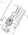
- Figure 1 illustrates a fluid dispensing device 100 in a "closed" mode of operation.
- the fluid dispensing device may, for example, be an aerosol spray device such as an aerosol can which provides fluid to be dispensed as a mist of particles. Only a partial section of such a can is illustrated in Figure 1 . It will be appreciated that other fluid dispensing devices which do not emit fluid as an aerosol may also be provided, for example devices emitting creams, gels, foams or the like.
- the fluid dispensing device 100 comprises a rigid container 105 on the top of which is mounted a valve assembly 110.
- the valve assembly 110 is held in a central position at the top of the container 105 by way of a mounting cup 115.
- the mounting cup 115 is selectively crimped around the edges of the rigid container 105 and around a region of the valve assembly 110 to thereby hermetically seal the container. Furthermore, an outer sealing gasket 118 and inner sealing gasket 120 may be provided in the regions proximate the crimped regions of the mounting cup 115 to support the sealing provided by the crimping process.
- crimping for example interference fits, liquid sealants and the like.
- a fluid reservoir 125 is provided within the sealed container and generally comprises a quantity of liquid (product) to be dispensed. Any liquid component is free to move in the container and will adopt a surface level due to gravitational effects.
- the fluid reservoir may be dispensed from the device (upon being “opened") by using a propellant contained within a head space 130 of the sealed container which "forces" the product to exit the container.
- the propellant may be a compressed gas such as carbon dioxide, nitrogen, air or the like.
- the propellant may be a liquid gas propellant such as butane, propane or the like. Mixtures of two or more gases may also be used as the propellant.
- the propellant may have some solubility with the fluid reservoir 125 and therefore upon dispersal of liquid product from the fluid reservoir, some propellant held as a liquid may also be dispersed.
- the gas in the head space may, for example, be at an initial pressure of 5 to 20 bar depending on the type of container in use.
- the initial pressure may, for example, be 9 to 12 bar.
- the present invention can also be used with higher pressure cans, for example, cans with an initial pressure of 18 bar or higher.
- the valve assembly 110 comprises an elongate valve stem 135 which can be moved in a reciprocating fashion along a primary stem axis 140 (represented by the broken line in Figure 1 ) upon pressing and releasing of an actuator 145 mounted to the valve stem.
- the elongate valve stem 135 sits in a first, closed position when no force is provided on the actuator and is held in this position by a resilient member 148 such as a spring.
- a resilient member 148 such as a spring.
- the actuator may be pressed and therefore selectively urged along the primary stem axis 140 to thereby overcome the force on the valve stem provided by the resilient member 148 and thereby urge the elongate valve stem 135 into a further, open position.
- the elongate valve stem When the elongate valve stem is in the further, open position, fluid is able to communicate between the inlet end 149 of the valve stem and the dispense nozzle 150, thereby producing an external aerosol spray which may be provided to a target (the further, open position is illustrated and described herein below).
- the valve assembly 110 further comprises an upper assembly body portion 155 and a lower assembly body portion 160 for housing the elongate valve stem and resilient member.
- the upper assembly body portion 155 and lower assembly body portion 160 of the valve assembly 110 are generally secured using a simple interference fit although it will be appreciated that other appropriate securing means, such as screw threads and the like, may be used.
- a projecting shoulder 165 of the valve stem abuts against an inwardly projecting lip 170 of the upper assembly body portion of the valve assembly to thereby sealingly engage the valve stem.
- the inner sealing gasket 120 when used, also contributes to sealingly engaging the valve stem. It will be appreciated that certain embodiments of the present invention are usable with other conventional valve assemblies/actuators.
- the projecting shoulder 165 Upon pressing the actuator and bringing the valve stem into the further, open position, the projecting shoulder 165 disengages from the inwardly projecting lip 170 and a first liquid inlet 175 of the valve stem moves to a location within the upper assembly body portion 155 beneath the inwardly projecting lip 170.
- This enables fluid communication between the inlet end 149 of the valve stem and the first liquid inlet 175 through at least one intermediate liquid outlet 176 of the valve stem which extends from the inlet end 149 substantially perpendicular to the primary stem axis to an inner wall 177 of the upper assembly body portion 155.
- axial grooves are provided in the projecting shoulder 165 at the interfaces between the at least one intermediate liquid outlet 176 and the inner wall 177 to facilitate flow of fluid into and out of the intermediate liquid outlets 176.
- a gas flow passageway 178 may be provided in the upper assembly body portion 155 to facilitate fluid communication with a further gas inlet 179 of the valve stem when the valve stem is in the further, open position.
- a neck region 180 of the valve assembly extends from the lower assembly body portion 160 and comprises a spigot 182.
- the spigot is connected to a housing body 190 according to the embodiment of the present invention shown in Figure 1 .
- the spigot 182 of the valve assembly can catch on an inwardly extending protruding ring of the housing body to help secure the parts and create a fluid tight seal.
- the housing body 190 could alternatively be integrally formed with the remainder of the valve assembly 110 as an extension of the lower assembly body portion 160. Having separate parts enables the housing body 190 and associated components (closure ball and dip tube) to be retrofitted to conventional valve assemblies.
- the housing body 190 is connected to a dip tube 192 locatable in fluid communication with the fluid reservoir 125 when the can is upright. It will be understood that when the fluid dispensing device 100 is tipped with respect to the primary stem axis 140, the dip tube 192 may no longer be in fluid communication with the fluid reservoir 125. Thus, when tipped, the housing body 190 provides a further fluid pathway in which fluid may still be communicated to the dispense nozzle 150.
- Figure 1 helps illustrate how a captive ball 195 is located in the housing.
- the ball is a smooth spherical object that freely rolls along a passageway in the housing. Other closure members that roll or slide on an abutment surface of the housing could of course be utilised.
- the ball is captive in the sense that valve seats at opposed end regions of a passage in which the ball rolls prevent the ball from escaping.
- FIG. 2 illustrates the housing body 190 in more detail.
- the housing body is a moulded plastic structure integrally formed in which an outer surface 200 has a number of openings. It could alternatively be a multi part structure and be constructed from other rigid, fluid tight materials. Other than the fluid ports the housing body is fluid tight.
- an external fluid port 210 is formed as a through hole through the housing body on a side wall 215.
- the through hole 210 thus provides an external fluid port in the housing body.
- the through hole shown has an elongate rectangular opening, however it will be appreciated that other shapes and indeed multiple openings could be used.
- the through hole may be provided at a different radial or axial location of the side wall 215 to that shown in Figure 2 .
- a first fluid communication passageway 220 extends within the housing body from the first external fluid port 210 towards an internal fluid port 225.
- the first fluid communication passageway 220 can help provide a fluid flow path for fluid, which may be gas and/or liquid, within the housing from the opening 210 in the side wall of the housing to the open central region within the housing body.
- the first fluid communication passageway 220 shown in Figure 2 extends from the internal fluid port 225 via a first substantially cylindrical portion 227 that has a constant circular cross section then via a valve seat 230 region into a wider fluid communication passageway portion 237.
- a further valve seat 240 is located towards an upper (in the orientation shown in Figure 2 ) end of the first fluid communication passageway.
- the further valve seat 240 is shown located at a further external fluid port 250.
- the further external fluid port 250 may be in fluid communication with the first fluid communication passageway. However, it will be appreciated that as an alternative this open area at the top (in the orientation shown in Figure 2 ) of the housing could be closed or covered to fluid flow. In such circumstances the ball locates on a suitable seating arrangement.
- the further valve seat 240 provides a seating position for the member that rolls or slides along the first fluid communication passageway to open or close a fluid flow path. The ball adopts this seated position when the can is tipped such that gravity causes the ball to roll to that end.
- Each valve seat 230, 240 is usable to permit a closure member such as a free ball (not shown in Figure 2 ) to become seated against respective seating surfaces.
- a closure member such as a free ball (not shown in Figure 2 )
- the closure member could be a body with a plurality of faces such as a snub dodecahedron, or the closure member could alternatively be a cylindrical or ellipsoid or the like shaped body.
- the housing body further includes a neck region 255 which is a generally cylindrical protrusion extending away from the main area of the housing body from a lower base (in the orientation shown in Figure 2 ).
- the neck region 255 ends in a spigot 260 to which a dip tube is connectable.
- a lumen 265 through the neck region provides a fluid communication passageway between a still further external fluid port 270 and the internal fluid port 225.
- fluid can flow through the first external fluid port 210 and/or the further external fluid port 250 and/or the still further external fluid port 270.
- Such fluid flows via the internal fluid port 225 into an exit fluid communication passageway 275 and from there via an open mouth 280 into the remainder of the valve assembly.
- the side wall defining the exit fluid communication passageway 275 may further comprise an inwardly extending protruding ring 282 which can secure the spigot 182 of the valve assembly to create a fluid tight seal.
- the housing body 190 could alternatively be integrally formed with the lower assembly body portion 160 with a minor modification since the neck region 180 and spigot 182 of the lower assembly body portion 160 would no longer be needed. This will be apparent to those skilled in the art.
- Figure 3 illustrates the fluid dispensing device 100 shown in Figure 1 in an "upside down" configuration.
- the fluid dispensing device 100 shown is an aerosol can and is shown in a dispense mode of operation when the can is upside down.
- Upside down means that the can is rotated approximately through 180 degrees with respect to the can orientation shown in Figure 1 .
- Figure 3 is thus representative of a user picking up the can with a hand, inverting the can and then depressing the actuator 145. This actuation urges the valve stem along the primary stem axis 140 urging it against the biasing effect of the spring.
- Figure 3 helps illustrate how the quantity of liquid product 125, which is free to move within the cavity of the container, has adopted a new position within the can.
- the surface 310 of the liquid is shown approximately half filling the container but in the position shown in Figure 3 the dip tube 192 will generally be out of fluid communication with the liquid reservoir 125. As liquid product is exhausted this level will drop over time.
- the external fluid port 210 on the side wall of the housing body is now located below the surface 310 of the liquid product.
- the ball 195 has become seated against the further valve seat 240.
- Fluid flow caused by the pressure of the head space 130 can now occur via the external fluid port 210 and the fluid communication passageway 220 to the internal fluid port 225 and from there to the dispense nozzle 150.
- the further valve seat 240 may not form a sealing engagement with the closure member 195 and may only prevent the closure member from escaping the passageway.
- fluid may also flow through the further external fluid port 250 around the closure member (albeit at a slower rate) and thus fluidly communicate with the first fluid communication pathway 220.
- Figure 4 illustrates the aerosol can 100 shown in Figure 3 as the spraying action is continued by keeping the actuator 145 depressed and raising a user's arm. This is a common motion when, for example spraying underarm deodorant.
- the can In the orientation shown in Figure 4 the can is shown in an approximately horizontal configuration. That is to say the can has been tipped approximately 90 degrees clockwise with respect to the initial upside down position illustrated in Figure 3 .
- the canister is tipped beyond a point where the ball moves away from the further valve seat 240 that is closer to the actuator/valve assembly.
- at least part of the radially outer most region of the inner surface of the fluid communication passageway 220 is inclined with respect to the primary stem axis. That is to say in use the ball rolls backwards and forwards within the housing body 190 along the fluid communication passageway 220 by rolling against an abutment surface provided by the inner surface of the fluid communication passageway.
- the fluid communication passageway does not have a common cross section.
- the ball will remain supported by a portion of the valve seat and the inclined region of the abutment surface even when the can is substantially horizontal (that is to say the user has tipped the can 90 degrees clockwise from the upside down position). Therefore, liquid is still able to flow through the external fluid port 210 in the side wall of the housing body. As a user continues to tip the canister further to return it to the upright position a point in time is reached where the inclined region becomes substantially horizontal with respect to the earth. At this point in time the ball will begin to roll along the abutment surface towards the valve seat 230.
- the fluid reservoir 125 When the can is tipped 90 degrees clockwise from the upside down position, the fluid reservoir 125 is still in fluid communication with the external fluid port 210 and thus liquid (product) remains able to flow through the fluid communication passageway 220 to the dispense nozzle 150. At the same time, the dip tube is not in fluid communication with the fluid reservoir or may only be partly in fluid communication therewith.
- Figure 5 illustrates the can 100 in a further state in which the can is further tipped back towards the vertical orientation. That is to say when the can has been moved from the "upside down" orientation shown in Figure 3 via the generally horizontal position shown in Figure 4 to a semi-upright position shown in Figure 5 .
- the can in Figure 5 is still in an open mode of operation with the actuator 145 still depressed and spray 300 still being ejected.
- the angle of tipping means that the body 125 of liquid product is angled across the inside of the can and the upper surface 310 of the liquid is shown below the level of the external fluid port 210 in the side wall of the housing body.
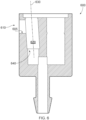
- the closure member may reciprocate along the passageway but will only open the passageway to allow fluid flow when an outer edge of the ball proximate the abutment surface rolls to a position above (in the orientation shown in Figure 6 ) a lower end 605 of the external fluid port 610.
- the diameter of the ball is substantially equal to the cross section of the fluid communication passageway.
- the ball will therefore only close the fluid communication passageway when the outer edge of the ball proximate the abutment surface rolls to a position below the lower end 605 of the external fluid port. If the ball is slightly smaller in diameter the closure occurs when the ball seats on the lower valve seat 640.
- the inclined region of the abutment surface in this embodiment will enable movement of the ball to be controlled in a similar fashion to the housing body illustrated in Figure 2 .
- the opening and/or closing of the fluid communication pathway 620 will have a greater dependency of the positioning of the ball within the passageway. That is to say that if a ball is used which has a diameter which is substantially equal to the cross-section of the passageway, the fluid communication passageway will only open and/or close once the outer edge of the ball proximate the abutment surface has reached and rolled passed the lower end of the external fluid port 610 (in one direction or the other).
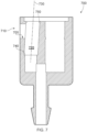
- the fluid communication passageway 720 of Figure 7 will only open and/or close once an outer edge of the ball proximate the abutment surface has reached and rolled passed a lower end 705 of the external fluid port 710 (in one direction or the other) due to the diameter of the ball being approximately equal to the cross-section of the passageway.
- a ball having a slightly smaller diameter fluid flow along the passageway 720 stops when the ball is seated on the lower valve seat 740.
- the inclined surface will result in a different effect on the ball (than the embodiment of Figure 6 , for example) when the can is tipped about its axis. That is to say that when the ball is tipped from the upright position towards the upside down position, the ball will remain seated at the first valve seat 740 when the can reaches a substantially horizontal position. Likewise, when tipping the can from the upside down position to the upright position, the ball will begin to roll along the inclined surface of the abutment surface away from the further valve seat 750 prior to the can reaching a horizontal position (when the inclined surface is substantially horizontal).
- This effect may be advantageous, for example, when the can is filled with a lower ratio of liquid product to propellant and/or a dip tube is used which has an end that sits proximate to a radially outer surface of the rigid container.
- a dip tube extends towards a radially outer edge of the rigid container in the direction in which the spray 300 will be emitted.
- the inclined surface in this embodiment will therefore ensure that the nozzle will have a greater likelihood, than that of a conventional device, of being in fluid communication with the liquid (product) as the can is tipped about 180 degrees (whilst the actuator is depressed).
Landscapes
- Chemical & Material Sciences (AREA)
- Dispersion Chemistry (AREA)
- Engineering & Computer Science (AREA)
- Mechanical Engineering (AREA)
- Containers And Packaging Bodies Having A Special Means To Remove Contents (AREA)
- Nozzles (AREA)
Claims (14)
- Vorrichtung zur Flüssigkeitsabgabe, umfassend:einen Gehäusekörper (190), der eine Vielzahl von externen Fluidöffnungen (210, 250, 270) umfasst, die mit einer Ventilbaugruppe (110) verbindbar oder so konfiguriert sind, dass sie einstückig mit dieser geformt ist, die einen länglichen Ventilschaft (135) beinhaltet, der einer jeweiligen primären Schaftachse (140) zugeordnet ist, undein Verschlusselement (195) in einem ersten Fluidkommunikationsdurchgang (220) im Gehäusekörper, das entlang des Durchgangs auf einer Anlagefläche des Gehäusekörpers rollt oder gleitet, um einen Fluidströmungsweg durch mindestens eine externe Fluidöffnung (210) selektiv zu schließen; wobeimindestens ein geneigter Bereich der Anlagefläche in Bezug auf die primäre Schaftachse geneigt ist, wobeider Gehäusekörper ferner einen ersten (230) und einen weiteren (240) Ventilsitz an gegenüberliegenden Endbereichen des ersten Fluidkommunikationsdurchgangs umfasst, und wobeider erste Fluidkommunikationsdurchgang einen Querschnitt aufweist, der sich entlang der Länge des Durchgangs zwischen dem ersten und weiteren Ventilsitz in Richtung der mindestens einen externen Fluidöffnung (210) konstant erweitert.
- Vorrichtung nach Anspruch 1, wobei:
das Verschlusselement (195) ein freies Kugelelement ist und die Anlagefläche eine Rollfläche umfasst, die dazu vorgesehen ist, dem Kugelelement zu ermöglichen, frei hin und her entlang des ersten Fluidkommunikationsdurchgangs zu rollen, wenn der Gehäusekörper gekippt wird. - Vorrichtung nach einem der vorhergehenden Ansprüche, wobei:
sich der erste Ventilsitz (230) an einem ersten Endbereich des ersten Fluidkommunikationsdurchgangs befindet und das Verschlusselement im ersten Ventilsitz in einer ersten Schließposition platzierbar ist, um dadurch den Fluidströmungsweg zu schließen. - Vorrichtung nach Anspruch 3, wobei:
sich der weitere Ventilsitz (240) an einem weiteren Endbereich des ersten Fluidkommunikationsdurchgangs distal zu einer internen Fluidöffnung (225) des Gehäusekörpers befindet, wobei das Verschlusselement im weiteren Ventilsitz in einer Sitzposition platzierbar ist. - Verfahren nach einem der Ansprüche 1 bis 3, ferner umfassend:
eine weitere externe Fluidöffnung (250) des Gehäusekörpers in Fluidkommunikation mit dem Fluidkommunikationsdurchgang ist in einem externen Endflächenbereich des Gehäusekörpers vorgesehen, der im Wesentlichen orthogonal zu einem externen Seitenflächenbereich des Gehäusekörpers ist, in dem sich die externe Fluidöffnung (210) befindet, wobei sich die weitere externe Fluidöffnung in der Nähe des weiteren Ventilsitzes befindet. - Vorrichtung nach Anspruch 5, ferner umfassend:der Gehäusekörper (190) umfasst ferner einen Halsbereich (255), der sich im Allgemeinen vom Rest des Gehäusekörpers weg erstreckt; undeine noch weitere externe Fluidöffnung (270) des Gehäusekörpers befindet sich in einem Endbereich des Halsbereichs in Fluidkommunikation mit einem inneren Lumen (265), das sich entlang des Halsbereichs von der noch weiteren externen Fluidöffnung zu einer internen Fluidöffnung (225) im Gehäusekörper erstreckt.
- Vorrichtung nach Anspruch 4, ferner umfassend:eine weitere externe Fluidöffnung (250) des Gehäusekörpers in Fluidkommunikation mit dem Fluidkommunikationsdurchgang ist in einem externen Endflächenbereich des Gehäusekörpers vorgesehen, der im Wesentlichen orthogonal zu einem externen Seitenflächenbereichdes Gehäusekörpers ist, in dem sich die externe Fluidöffnung (210) befindet, wobei sich die weitere externe Fluidöffnung in der Nähe des weiteren Ventilsitzes befindet.
- Vorrichtung nach Anspruch 7, ferner umfassend:der Gehäusekörper (190) umfasst ferner einen Halsbereich (255), der sich im Allgemeinen vom Rest des Gehäusekörpers weg erstreckt; undeine noch weitere externe Fluidöffnung (270) des Gehäusekörpers befindet sich in einem Endbereich des Halsbereichs in Fluidkommunikation mit einem inneren Lumen (265), das sich entlang des Halsbereichs von der noch weiteren externen Fluidöffnung zu der internen Fluidöffnung (225) im Gehäusekörper erstreckt.
- Vorrichtung nach einem der Ansprüche 1 bis 3 oder Anspruch 5, wobei:
der Gehäusekörper (190) ferner eine externe Fluidauslassöffnung umfasst, um dem länglichen Ventilschaft Fluid bereitzustellen. - Vorrichtung nach Anspruch 9, wobei:
der Gehäusekörper (190) ferner einen weiteren Fluidkommunikationsdurchgang umfasst, der sich zwischen der externen Fluidaustrittsöffnung und einer internen Fluidöffnung (225) im Gehäusekörper erstreckt. - Vorrichtung nach Anspruch 4 oder einem der Ansprüche 6 bis 8, wobei:
der Gehäusekörper (190) ferner eine externe Fluidauslassöffnung umfasst, um dem länglichen Ventilschaft Fluid bereitzustellen. - Vorrichtung nach Anspruch 11, wobei:
der Gehäusekörper (190) ferner einen weiteren Fluidkommunikationsdurchgang umfasst, der sich zwischen der externen Fluidaustrittsöffnung und der internen Fluidöffnung (225) im Gehäusekörper erstreckt. - Vorrichtung nach einem der vorhergehenden Ansprüche, wobei:
der geneigte Bereich der Anlagefläche gegenüber der primären Schaftachse (140) um 1° bis 20° und optional um 4° bis 10° geneigt ist. - Vorrichtung nach einem der vorhergehenden Ansprüche, ferner umfassend:einen unter Druck stehenden oder druckbeaufschlagbaren Behälter (105) zum Bereitstellen eines Fluidvorratsbehälters (125), wobeider Behälter zur Aufnahme einer abzugebenden Flüssigkeit dient; undder Behälter zur Aufnahme eines Gases mit einer Temperatur von etwa 25 °C und einem Druck von mindestens 30 bar und optional eines Gases mit einer Temperatur von etwa 25 °C und einem Druck von mindestens 50 bar dient.
Applications Claiming Priority (2)
| Application Number | Priority Date | Filing Date | Title |
|---|---|---|---|
| GBGB1801519.8A GB201801519D0 (en) | 2018-01-30 | 2018-01-30 | Fluid dispensing |
| PCT/GB2019/050223 WO2019150084A1 (en) | 2018-01-30 | 2019-01-28 | Fluid dispensing |
Publications (3)
| Publication Number | Publication Date |
|---|---|
| EP3746376A1 EP3746376A1 (de) | 2020-12-09 |
| EP3746376C0 EP3746376C0 (de) | 2023-09-27 |
| EP3746376B1 true EP3746376B1 (de) | 2023-09-27 |
Family
ID=61558287
Family Applications (1)
| Application Number | Title | Priority Date | Filing Date |
|---|---|---|---|
| EP19702961.4A Active EP3746376B1 (de) | 2018-01-30 | 2019-01-28 | Flüssigkeitsspender |
Country Status (3)
| Country | Link |
|---|---|
| EP (1) | EP3746376B1 (de) |
| GB (1) | GB201801519D0 (de) |
| WO (1) | WO2019150084A1 (de) |
Families Citing this family (1)
| Publication number | Priority date | Publication date | Assignee | Title |
|---|---|---|---|---|
| GB202300898D0 (en) * | 2023-01-20 | 2023-03-08 | Salford Valve Company Ltd | Fluid dispensing |
Family Cites Families (4)
| Publication number | Priority date | Publication date | Assignee | Title |
|---|---|---|---|---|
| DE7924419U1 (de) * | 1979-08-28 | 1980-01-10 | Perfect Ventil Gmbh | Aerosoldose |
| CH669369A5 (en) * | 1986-02-19 | 1989-03-15 | Werding Winfried J | Valve for aerosol dispenser - incorporates ridged piston to seal into soft sealing plug |
| US5803319A (en) * | 1996-01-19 | 1998-09-08 | Summit Packaging Systems, Inc. | Invertible spray valve and container containing same |
| KR101185101B1 (ko) * | 2010-11-17 | 2012-09-21 | 남방씨.엔.에이 주식회사 | 중력 밸브 및 이를 이용한 가스 스프레이 캔 |
-
2018
- 2018-01-30 GB GBGB1801519.8A patent/GB201801519D0/en not_active Ceased
-
2019
- 2019-01-28 EP EP19702961.4A patent/EP3746376B1/de active Active
- 2019-01-28 WO PCT/GB2019/050223 patent/WO2019150084A1/en not_active Ceased
Also Published As
| Publication number | Publication date |
|---|---|
| EP3746376C0 (de) | 2023-09-27 |
| WO2019150084A1 (en) | 2019-08-08 |
| GB201801519D0 (en) | 2018-03-14 |
| EP3746376A1 (de) | 2020-12-09 |
Similar Documents
| Publication | Publication Date | Title |
|---|---|---|
| US4116370A (en) | Vapor tap valve for aerosol containers used with flammable propellants | |
| JP6889214B2 (ja) | 分割体又は多孔質材料を含む流体溜めを有するディスペンサー | |
| JP6626098B2 (ja) | バルブアセンブリ | |
| US5695096A (en) | Dispensing valve and dispensing container equipped with such a valve | |
| US20100044400A1 (en) | Valve for a pressurised dispenser comprising inlet orifices being deformable by the internal pressure | |
| US8820588B2 (en) | Liquid dispensing apparatus | |
| GB2475393A (en) | Aerosol spray device with valve arrangement having low coefficient of loss | |
| CN106927148A (zh) | 排放组件、液体分配仪器以及计量剂量的药物吸入器 | |
| KR102923967B1 (ko) | 액체 물질을 분배하기에 적합한 장치 | |
| EP3746376A1 (de) | Flüssigkeitsspender | |
| GB2556420A (en) | Canister valve | |
| EP0000062A1 (de) | Ventil für Aerosolbehälter mit entflammbaren Treibmitteln und damit ausgerüsteter Behälter | |
| US11745198B2 (en) | Set of dispensing containers and a main dispensing container | |
| AU2024210058A1 (en) | Fluid dispensing | |
| US20160003367A1 (en) | Springless regulator |
Legal Events
| Date | Code | Title | Description |
|---|---|---|---|
| STAA | Information on the status of an ep patent application or granted ep patent |
Free format text: STATUS: UNKNOWN |
|
| STAA | Information on the status of an ep patent application or granted ep patent |
Free format text: STATUS: THE INTERNATIONAL PUBLICATION HAS BEEN MADE |
|
| PUAI | Public reference made under article 153(3) epc to a published international application that has entered the european phase |
Free format text: ORIGINAL CODE: 0009012 |
|
| STAA | Information on the status of an ep patent application or granted ep patent |
Free format text: STATUS: REQUEST FOR EXAMINATION WAS MADE |
|
| 17P | Request for examination filed |
Effective date: 20200724 |
|
| AK | Designated contracting states |
Kind code of ref document: A1 Designated state(s): AL AT BE BG CH CY CZ DE DK EE ES FI FR GB GR HR HU IE IS IT LI LT LU LV MC MK MT NL NO PL PT RO RS SE SI SK SM TR |
|
| AX | Request for extension of the european patent |
Extension state: BA ME |
|
| DAV | Request for validation of the european patent (deleted) | ||
| DAX | Request for extension of the european patent (deleted) | ||
| STAA | Information on the status of an ep patent application or granted ep patent |
Free format text: STATUS: EXAMINATION IS IN PROGRESS |
|
| 17Q | First examination report despatched |
Effective date: 20220221 |
|
| GRAP | Despatch of communication of intention to grant a patent |
Free format text: ORIGINAL CODE: EPIDOSNIGR1 |
|
| STAA | Information on the status of an ep patent application or granted ep patent |
Free format text: STATUS: GRANT OF PATENT IS INTENDED |
|
| INTG | Intention to grant announced |
Effective date: 20230605 |
|
| GRAS | Grant fee paid |
Free format text: ORIGINAL CODE: EPIDOSNIGR3 |
|
| GRAA | (expected) grant |
Free format text: ORIGINAL CODE: 0009210 |
|
| STAA | Information on the status of an ep patent application or granted ep patent |
Free format text: STATUS: THE PATENT HAS BEEN GRANTED |
|
| AK | Designated contracting states |
Kind code of ref document: B1 Designated state(s): AL AT BE BG CH CY CZ DE DK EE ES FI FR GB GR HR HU IE IS IT LI LT LU LV MC MK MT NL NO PL PT RO RS SE SI SK SM TR |
|
| REG | Reference to a national code |
Ref country code: GB Ref legal event code: FG4D |
|
| REG | Reference to a national code |
Ref country code: CH Ref legal event code: EP |
|
| REG | Reference to a national code |
Ref country code: DE Ref legal event code: R096 Ref document number: 602019038148 Country of ref document: DE |
|
| REG | Reference to a national code |
Ref country code: IE Ref legal event code: FG4D |
|
| U01 | Request for unitary effect filed |
Effective date: 20231010 |
|
| U07 | Unitary effect registered |
Designated state(s): AT BE BG DE DK EE FI FR IT LT LU LV MT NL PT SE SI Effective date: 20231018 |
|
| PG25 | Lapsed in a contracting state [announced via postgrant information from national office to epo] |
Ref country code: GR Free format text: LAPSE BECAUSE OF FAILURE TO SUBMIT A TRANSLATION OF THE DESCRIPTION OR TO PAY THE FEE WITHIN THE PRESCRIBED TIME-LIMIT Effective date: 20231228 |
|
| PG25 | Lapsed in a contracting state [announced via postgrant information from national office to epo] |
Ref country code: RS Free format text: LAPSE BECAUSE OF FAILURE TO SUBMIT A TRANSLATION OF THE DESCRIPTION OR TO PAY THE FEE WITHIN THE PRESCRIBED TIME-LIMIT Effective date: 20230927 Ref country code: NO Free format text: LAPSE BECAUSE OF FAILURE TO SUBMIT A TRANSLATION OF THE DESCRIPTION OR TO PAY THE FEE WITHIN THE PRESCRIBED TIME-LIMIT Effective date: 20231227 Ref country code: GR Free format text: LAPSE BECAUSE OF FAILURE TO SUBMIT A TRANSLATION OF THE DESCRIPTION OR TO PAY THE FEE WITHIN THE PRESCRIBED TIME-LIMIT Effective date: 20231228 |
|
| U20 | Renewal fee for the european patent with unitary effect paid |
Year of fee payment: 6 Effective date: 20240108 |
|
| U1N | Appointed representative for the unitary patent procedure changed after the registration of the unitary effect |
Representative=s name: ST CLAIR JONES, GREGORY ARTHUR LANGLEY; GB |
|
| PG25 | Lapsed in a contracting state [announced via postgrant information from national office to epo] |
Ref country code: IS Free format text: LAPSE BECAUSE OF FAILURE TO SUBMIT A TRANSLATION OF THE DESCRIPTION OR TO PAY THE FEE WITHIN THE PRESCRIBED TIME-LIMIT Effective date: 20240127 |
|
| PG25 | Lapsed in a contracting state [announced via postgrant information from national office to epo] |
Ref country code: ES Free format text: LAPSE BECAUSE OF FAILURE TO SUBMIT A TRANSLATION OF THE DESCRIPTION OR TO PAY THE FEE WITHIN THE PRESCRIBED TIME-LIMIT Effective date: 20230927 |
|
| PG25 | Lapsed in a contracting state [announced via postgrant information from national office to epo] |
Ref country code: SM Free format text: LAPSE BECAUSE OF FAILURE TO SUBMIT A TRANSLATION OF THE DESCRIPTION OR TO PAY THE FEE WITHIN THE PRESCRIBED TIME-LIMIT Effective date: 20230927 Ref country code: RO Free format text: LAPSE BECAUSE OF FAILURE TO SUBMIT A TRANSLATION OF THE DESCRIPTION OR TO PAY THE FEE WITHIN THE PRESCRIBED TIME-LIMIT Effective date: 20230927 Ref country code: IS Free format text: LAPSE BECAUSE OF FAILURE TO SUBMIT A TRANSLATION OF THE DESCRIPTION OR TO PAY THE FEE WITHIN THE PRESCRIBED TIME-LIMIT Effective date: 20240127 Ref country code: ES Free format text: LAPSE BECAUSE OF FAILURE TO SUBMIT A TRANSLATION OF THE DESCRIPTION OR TO PAY THE FEE WITHIN THE PRESCRIBED TIME-LIMIT Effective date: 20230927 Ref country code: CZ Free format text: LAPSE BECAUSE OF FAILURE TO SUBMIT A TRANSLATION OF THE DESCRIPTION OR TO PAY THE FEE WITHIN THE PRESCRIBED TIME-LIMIT Effective date: 20230927 Ref country code: SK Free format text: LAPSE BECAUSE OF FAILURE TO SUBMIT A TRANSLATION OF THE DESCRIPTION OR TO PAY THE FEE WITHIN THE PRESCRIBED TIME-LIMIT Effective date: 20230927 |
|
| PG25 | Lapsed in a contracting state [announced via postgrant information from national office to epo] |
Ref country code: PL Free format text: LAPSE BECAUSE OF FAILURE TO SUBMIT A TRANSLATION OF THE DESCRIPTION OR TO PAY THE FEE WITHIN THE PRESCRIBED TIME-LIMIT Effective date: 20230927 |
|
| REG | Reference to a national code |
Ref country code: DE Ref legal event code: R097 Ref document number: 602019038148 Country of ref document: DE |
|
| PLBE | No opposition filed within time limit |
Free format text: ORIGINAL CODE: 0009261 |
|
| STAA | Information on the status of an ep patent application or granted ep patent |
Free format text: STATUS: NO OPPOSITION FILED WITHIN TIME LIMIT |
|
| PG25 | Lapsed in a contracting state [announced via postgrant information from national office to epo] |
Ref country code: MC Free format text: LAPSE BECAUSE OF FAILURE TO SUBMIT A TRANSLATION OF THE DESCRIPTION OR TO PAY THE FEE WITHIN THE PRESCRIBED TIME-LIMIT Effective date: 20230927 |
|
| PG25 | Lapsed in a contracting state [announced via postgrant information from national office to epo] |
Ref country code: MC Free format text: LAPSE BECAUSE OF FAILURE TO SUBMIT A TRANSLATION OF THE DESCRIPTION OR TO PAY THE FEE WITHIN THE PRESCRIBED TIME-LIMIT Effective date: 20230927 |
|
| REG | Reference to a national code |
Ref country code: CH Ref legal event code: PL |
|
| 26N | No opposition filed |
Effective date: 20240628 |
|
| PG25 | Lapsed in a contracting state [announced via postgrant information from national office to epo] |
Ref country code: CH Free format text: LAPSE BECAUSE OF NON-PAYMENT OF DUE FEES Effective date: 20240131 |
|
| PG25 | Lapsed in a contracting state [announced via postgrant information from national office to epo] |
Ref country code: CH Free format text: LAPSE BECAUSE OF NON-PAYMENT OF DUE FEES Effective date: 20240131 |
|
| PG25 | Lapsed in a contracting state [announced via postgrant information from national office to epo] |
Ref country code: IE Free format text: LAPSE BECAUSE OF NON-PAYMENT OF DUE FEES Effective date: 20240128 |
|
| PG25 | Lapsed in a contracting state [announced via postgrant information from national office to epo] |
Ref country code: IE Free format text: LAPSE BECAUSE OF NON-PAYMENT OF DUE FEES Effective date: 20240128 |
|
| U20 | Renewal fee for the european patent with unitary effect paid |
Year of fee payment: 7 Effective date: 20250109 |
|
| PG25 | Lapsed in a contracting state [announced via postgrant information from national office to epo] |
Ref country code: HR Free format text: LAPSE BECAUSE OF FAILURE TO SUBMIT A TRANSLATION OF THE DESCRIPTION OR TO PAY THE FEE WITHIN THE PRESCRIBED TIME-LIMIT Effective date: 20230927 |
|
| PG25 | Lapsed in a contracting state [announced via postgrant information from national office to epo] |
Ref country code: CY Free format text: LAPSE BECAUSE OF FAILURE TO SUBMIT A TRANSLATION OF THE DESCRIPTION OR TO PAY THE FEE WITHIN THE PRESCRIBED TIME-LIMIT; INVALID AB INITIO Effective date: 20190128 |
|
| PG25 | Lapsed in a contracting state [announced via postgrant information from national office to epo] |
Ref country code: HU Free format text: LAPSE BECAUSE OF FAILURE TO SUBMIT A TRANSLATION OF THE DESCRIPTION OR TO PAY THE FEE WITHIN THE PRESCRIBED TIME-LIMIT; INVALID AB INITIO Effective date: 20190128 |
|
| PG25 | Lapsed in a contracting state [announced via postgrant information from national office to epo] |
Ref country code: TR Free format text: LAPSE BECAUSE OF FAILURE TO SUBMIT A TRANSLATION OF THE DESCRIPTION OR TO PAY THE FEE WITHIN THE PRESCRIBED TIME-LIMIT Effective date: 20230927 |
|
| U20 | Renewal fee for the european patent with unitary effect paid |
Year of fee payment: 8 Effective date: 20260109 |
|
| PGFP | Annual fee paid to national office [announced via postgrant information from national office to epo] |
Ref country code: GB Payment date: 20260109 Year of fee payment: 8 |