EP3746330B1 - A new type trailer body structure - Google Patents
A new type trailer body structure Download PDFInfo
- Publication number
- EP3746330B1 EP3746330B1 EP19814732.4A EP19814732A EP3746330B1 EP 3746330 B1 EP3746330 B1 EP 3746330B1 EP 19814732 A EP19814732 A EP 19814732A EP 3746330 B1 EP3746330 B1 EP 3746330B1
- Authority
- EP
- European Patent Office
- Prior art keywords
- trailer
- section
- sheet metal
- welding line
- tank
- Prior art date
- Legal status (The legal status is an assumption and is not a legal conclusion. Google has not performed a legal analysis and makes no representation as to the accuracy of the status listed.)
- Active
Links
Images
Classifications
-
- B—PERFORMING OPERATIONS; TRANSPORTING
- B60—VEHICLES IN GENERAL
- B60P—VEHICLES ADAPTED FOR LOAD TRANSPORTATION OR TO TRANSPORT, TO CARRY, OR TO COMPRISE SPECIAL LOADS OR OBJECTS
- B60P3/00—Vehicles adapted to transport, to carry or to comprise special loads or objects
- B60P3/22—Tank vehicles
- B60P3/2205—Constructional features
- B60P3/221—Assembling, e.g. layout of steel plates or reinforcing arrangements
Definitions
- the present invention is related to a body structure differentiated with the welding process applied on the trailer tank.
- the present invention is particularly related to a trailer body structure which is improved with a revision made on the welding lines created during joining sheet metals of the body in the trailer tank.
- the trailer is a highway vehicle used for freightage designed according to the load it will carry, pulled by a motor vehicle and comprises at least one axle shaft and connection equipment which enables it to connect to a vehicle.
- the dimensions of the trailers and journey conditions are determined by Highway Traffic Legislation.
- the trailers are the vehicles which can be used in transporting and carrying any heavy load including the dangerous materials.
- the trailers consist of baffle and dished head sections that are located in determined intervals successively and a body section formed with the body sheet metals of said sections. Adapting the body sheet metals to the dished head sections in a manner to form the body is obtained by using welding methods.
- a welding method used for the trailer is disclosed in the application No US3000340 .
- all welding lines are structures vertically to the floor in order to create the trailer body.
- This situation is also applied in standard trailer configurations.
- this vertical direction welding line created in adapting the conical sheet metals of the body makes it difficult to obtain product with the required bending strength.
- the thickness of the sheet metals shall be increased to 7- 8mm. The increase made in the sheet metals causes the vehicle to which the trailer is connected to have difficulty, it increases the loads coming to the axle shaft of the vehicle and it brings more fuel consumption into question.
- the present invention discloses a tank trailer for transporting flowable material.
- the tank trailer includes a low-profile tank having a rear section, a front section, and a transitional section.
- the transitional section connects the rear section and the front section such that flowable material can flow among the sections.
- the rear section has a rear circumference and a rear center of gravity.
- the front section has a front circumference and a front center of gravity. The front circumference is smaller than the rear circumference, and the rear center of gravity is lower than the front center of gravity.
- the front section and the transitional section are frameless.
- the tank trailer also includes a trailer suspension operatively connected to the rear section.
- the present invention is related to a trailer body in which a revision is made in the welding line of the conical body section in order to eliminate the abovementioned disadvantages and bring new advantages to the relevant technical field.
- the main purpose of the invention is to provide a trailer body which prevents increasing the sheet metals thickness in obtaining required bending strength.
- Another purpose of the invention is to provide a trailer body which enables to decrease the difficulties and loads on the vehicle whereupon the trailer is connected.
- Another purpose of the invention is to provide a trailer body which prevents the increase in the fuel consumption.
- the present invention is a trailer body structure defined by dished heads and a rear body sheet metal which surrounds said dished heads and a front conical section with a middle conical body sheet metal there between, characterized in that said trailer body structure comprises at least one inclined welding line configured in a manner to provide joining said middle conical body with the rear body sheet metal and said front cone sheet metal, whereby said front conical section comprises at least one inclined welding line and is configured with a welding line angle towards the body and less than 90°, the inclined welding line being configured in a manner to provide an incline in the middle conical body sheet metal with respect to the rear body sheet metal and to the front conical section.
- Said trailer (10) basically consists of wheels (11) and a body (12) mounted on said wheels (11).
- Said body (12) consists of a front dished head section (121 ) aligned successively, a first baffle (122), a second baffle (123), a front conical section (124), an interval dished head section (125) and a rear dished head section (126).
- Said front dished head section (121) closes the front section of the trailer (10) tank and corresponds to the pressure of the substance within the tank during vehicle moving or braking.
- Said first baffle (122) is used to prevent shaking in the trailer (10) tank division with a net volume exceeding 7500 liters and to provide the vehicle move more stably and consists of a dished head whereupon some holes are created on predetermined sections.
- Said second baffle (123) also consists of a dished head on which holes are created and prevents shaking of the passage section of the tank.
- Said front conical section (124) is the section which provides flexibility to the trailer (10) body. The middle conical body (14) provides that no product is left within the trailer (10) tank, it also provides to adjust the height of the trailer (10) tank according to the height of the towing vehicle.
- Said interval dished head section (125) is the dished head which prevents passage of the substance between two divisions of the trailer (10) tank and balances the pressure caused by the substance carried in the relevant section.
- Said rear dished head section (126) is the dished head used for providing impermeability at the rear section of the trailer (10) tank and corresponds to the pressure caused by the material carried when the vehicle moves.
- This section that constitutes the body (12) is covered by the rear body sheet metal (13) and middle conical body (14) sheet metal.
- Said rear body sheet metal (13) provides impermeability by surrounding the dished head sections that create post middle conical body (14) sheet metal of the trailer (10) tank.
- Said middle conical body (14) sheet metal provides impermeability by surrounding the dished head sections that create post front conical section (124) of the trailer (10) tank.
- the rear body sheet metal (13) and middle conical body (14) sheet metal are obtained by bending the sheet metal with a strength which can be durable against the shaking of the carried substance within the trailer (10) tank and the pressure created by this shaking.
- the rear body sheet metal (13), the middle conical body (14) sheet metal and the front conical section (124) provide integrity in the trailer (10) body by being mounted with welding methods to the dished head sections.
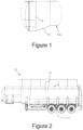
- FIG. 1 A prior art view in respect to the welding line (A) made during mounting of the front conical section (124) is given in Figure 1 .
- the welding line (A) created for mounting is configured with a 90° welding line angle (x) according to the floor.
- the thickness of the sheet metal shall be increased to 7- 8mm. The increase made in the sheet metal causes the vehicle to which the trailer (10) is connected to have difficulty, it increases the loads coming to the axle shaft of the vehicle and it brings more fuel consumption into question.
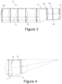
- FIG. 4 A detailed view of the middle conical body (14) created for eliminating said problems is given in Figure 4 .
- the middle conical body (14) of the present invention, the inclined welding line (B) created for mounting process is configured with a welding line angle (x) less than 90° according to the floor. Therefore, without requiring an increase in the thickness of the material, it shall be possible to reach the required bending strength.
- the middle conical body (14) provides to obtain a more flexible trailer (10) tank structure due to the incline by means of the welding line angle (x).
Landscapes
- Engineering & Computer Science (AREA)
- Health & Medical Sciences (AREA)
- Public Health (AREA)
- Transportation (AREA)
- Mechanical Engineering (AREA)
- Butt Welding And Welding Of Specific Article (AREA)
- Tires In General (AREA)
- Cooling, Air Intake And Gas Exhaust, And Fuel Tank Arrangements In Propulsion Units (AREA)
- Vessels, Lead-In Wires, Accessory Apparatuses For Cathode-Ray Tubes (AREA)
Description
- The present invention is related to a body structure differentiated with the welding process applied on the trailer tank.
- The present invention is particularly related to a trailer body structure which is improved with a revision made on the welding lines created during joining sheet metals of the body in the trailer tank.
- The trailer is a highway vehicle used for freightage designed according to the load it will carry, pulled by a motor vehicle and comprises at least one axle shaft and connection equipment which enables it to connect to a vehicle. The dimensions of the trailers and journey conditions are determined by Highway Traffic Legislation. The trailers are the vehicles which can be used in transporting and carrying any heavy load including the dangerous materials. Basically the trailers consist of baffle and dished head sections that are located in determined intervals successively and a body section formed with the body sheet metals of said sections. Adapting the body sheet metals to the dished head sections in a manner to form the body is obtained by using welding methods.
- A welding method used for the trailer is disclosed in the application No
US3000340 . In said application it is seen that all welding lines are structures vertically to the floor in order to create the trailer body. This situation is also applied in standard trailer configurations. Particularly this vertical direction welding line created in adapting the conical sheet metals of the body makes it difficult to obtain product with the required bending strength. In this case in order to provide required strength values, the thickness of the sheet metals shall be increased to 7- 8mm. The increase made in the sheet metals causes the vehicle to which the trailer is connected to have difficulty, it increases the loads coming to the axle shaft of the vehicle and it brings more fuel consumption into question. - The patent application numbered
US2011/148091A1 is found in the literature regarding the subject matter. The present invention discloses a tank trailer for transporting flowable material. The tank trailer includes a low-profile tank having a rear section, a front section, and a transitional section. The transitional section connects the rear section and the front section such that flowable material can flow among the sections. The rear section has a rear circumference and a rear center of gravity. The front section has a front circumference and a front center of gravity. The front circumference is smaller than the rear circumference, and the rear center of gravity is lower than the front center of gravity. The front section and the transitional section are frameless. The tank trailer also includes a trailer suspension operatively connected to the rear section. - As a result of this the abovementioned problems that cannot be solved under the light of the prior art make it necessary to make an improvement in the relevant technical field.
- The present invention is related to a trailer body in which a revision is made in the welding line of the conical body section in order to eliminate the abovementioned disadvantages and bring new advantages to the relevant technical field.
- The main purpose of the invention is to provide a trailer body which prevents increasing the sheet metals thickness in obtaining required bending strength.
- Another purpose of the invention is to provide a trailer body which enables to decrease the difficulties and loads on the vehicle whereupon the trailer is connected.
- Another purpose of the invention is to provide a trailer body which prevents the increase in the fuel consumption.
- In order to fulfill all purpose mentioned above and arise out of the following detailed description, the present invention is a trailer body structure defined by dished heads and a rear body sheet metal which surrounds said dished heads and a front conical section with a middle conical body sheet metal there between, characterized in that said trailer body structure comprises at least one inclined welding line configured in a manner to provide joining said middle conical body with the rear body sheet metal and said front cone sheet metal, whereby said front conical section comprises at least one inclined welding line and is configured with a welding line angle towards the body and less than 90°, the inclined welding line being configured in a manner to provide an incline in the middle conical body sheet metal with respect to the rear body sheet metal and to the front conical section.
- In order to fully understand the embodiment of the present invention and advantages with additional elements, it shall be evaluated by the following figures with the description below.
-
-
Figure 1 is a detailed view of the middle conical body in respect to the prior art. -
Figure 2 is a general view of the trailer. -
Figure 3 is a general view of the trailer body. -
Figure 4 is a detailed view of the middle conical body. -
- 10 Trailer
- 11 Wheels
- 12 Body
- 121 Front Dished Head Section
- 122 First Baffle
- 123 Second Baffle
- 124 Front Conical Section
- 125 Interval Dished Head Section
- 126 Rear Dished Head Section
- 13 Rear Body Sheet Metal
- 14 Middle Conical Body
- A: Welding Line
- B: Inclined Welding Line
- x: Welding Line Angle
- In this detailed description, the novelty of the present invention is described with examples in a manner without any limiting effect only to clarify the subject matter.
- The general view of a trailer (10) is given in
Figure 2 . Said trailer (10) basically consists of wheels (11) and a body (12) mounted on said wheels (11). Said body (12) consists of a front dished head section (121 ) aligned successively, a first baffle (122), a second baffle (123), a front conical section (124), an interval dished head section (125) and a rear dished head section (126). Said front dished head section (121) closes the front section of the trailer (10) tank and corresponds to the pressure of the substance within the tank during vehicle moving or braking. Said first baffle (122) is used to prevent shaking in the trailer (10) tank division with a net volume exceeding 7500 liters and to provide the vehicle move more stably and consists of a dished head whereupon some holes are created on predetermined sections. Said second baffle (123) also consists of a dished head on which holes are created and prevents shaking of the passage section of the tank. Said front conical section (124) is the section which provides flexibility to the trailer (10) body. The middle conical body (14) provides that no product is left within the trailer (10) tank, it also provides to adjust the height of the trailer (10) tank according to the height of the towing vehicle. Said interval dished head section (125) is the dished head which prevents passage of the substance between two divisions of the trailer (10) tank and balances the pressure caused by the substance carried in the relevant section. Said rear dished head section (126) is the dished head used for providing impermeability at the rear section of the trailer (10) tank and corresponds to the pressure caused by the material carried when the vehicle moves. - This section that constitutes the body (12) is covered by the rear body sheet metal (13) and middle conical body (14) sheet metal. Said rear body sheet metal (13) provides impermeability by surrounding the dished head sections that create post middle conical body (14) sheet metal of the trailer (10) tank. Said middle conical body (14) sheet metal provides impermeability by surrounding the dished head sections that create post front conical section (124) of the trailer (10) tank. The rear body sheet metal (13) and middle conical body (14) sheet metal are obtained by bending the sheet metal with a strength which can be durable against the shaking of the carried substance within the trailer (10) tank and the pressure created by this shaking. The rear body sheet metal (13), the middle conical body (14) sheet metal and the front conical section (124) provide integrity in the trailer (10) body by being mounted with welding methods to the dished head sections.
- A prior art view in respect to the welding line (A) made during mounting of the front conical section (124) is given in
Figure 1 . The welding line (A) created for mounting is configured with a 90° welding line angle (x) according to the floor. In this case in order to provide required strength values, the thickness of the sheet metal shall be increased to 7- 8mm. The increase made in the sheet metal causes the vehicle to which the trailer (10) is connected to have difficulty, it increases the loads coming to the axle shaft of the vehicle and it brings more fuel consumption into question. - A detailed view of the middle conical body (14) created for eliminating said problems is given in
Figure 4 . The middle conical body (14) of the present invention, the inclined welding line (B) created for mounting process is configured with a welding line angle (x) less than 90° according to the floor. Therefore, without requiring an increase in the thickness of the material, it shall be possible to reach the required bending strength. The middle conical body (14) provides to obtain a more flexible trailer (10) tank structure due to the incline by means of the welding line angle (x).
Claims (1)
- A trailer (10) body (12) structure defined by dished heads and a rear body sheet metal (13) which surrounds said dished heads and a front conical section (124) with a middle conical body (14) sheet metal there between, characterized in that said trailer (10) body (12) structure comprises at least one inclined welding line (B) configured in a manner to provide joining said middle conical body (14) with the rear body sheet metal (13) and said front cone sheet metal (13), whereby said front conical section (124) comprises at least one inclined welding line (B) and is configured with a welding line angle (x) towards the body (12) and less than 90°, the inclined welding line (B) being configured in a manner to provide an incline in the middle conical body (14) sheet metal with respect to the rear body sheet metal and to the front conical section (124).
Applications Claiming Priority (2)
| Application Number | Priority Date | Filing Date | Title |
|---|---|---|---|
| TR2018/02377A TR201802377A2 (en) | 2018-02-20 | 2018-02-20 | CONSTRUCTION OF A NEW TYPE TRAILER BODY |
| PCT/TR2019/050097 WO2019236036A2 (en) | 2018-02-20 | 2019-02-14 | A new type trailer body structure |
Publications (4)
| Publication Number | Publication Date |
|---|---|
| EP3746330A2 EP3746330A2 (en) | 2020-12-09 |
| EP3746330A4 EP3746330A4 (en) | 2021-03-24 |
| EP3746330B1 true EP3746330B1 (en) | 2023-10-18 |
| EP3746330C0 EP3746330C0 (en) | 2023-10-18 |
Family
ID=63794191
Family Applications (1)
| Application Number | Title | Priority Date | Filing Date |
|---|---|---|---|
| EP19814732.4A Active EP3746330B1 (en) | 2018-02-20 | 2019-02-14 | A new type trailer body structure |
Country Status (3)
| Country | Link |
|---|---|
| EP (1) | EP3746330B1 (en) |
| TR (1) | TR201802377A2 (en) |
| WO (1) | WO2019236036A2 (en) |
Family Cites Families (6)
| Publication number | Priority date | Publication date | Assignee | Title |
|---|---|---|---|---|
| US3000340A (en) | 1956-02-03 | 1961-09-19 | Fruehauf Trailer Co | Method of making a welded trailer tank |
| FR2943995B1 (en) * | 2009-04-03 | 2011-03-25 | Ets Magyar | TRONCON IN COMPOSITE MATERIAL FOR TANK VEHICLE |
| US8523232B2 (en) | 2009-12-23 | 2013-09-03 | Jose (Joey) M. DeLaRosa, II | Low-profile tank trailer for transporting flowable material |
| US8801040B2 (en) * | 2012-06-12 | 2014-08-12 | Timothy Scott Thomas | Low-profile vacuum tank trailer for transporting flowable material |
| US9789916B1 (en) * | 2013-10-16 | 2017-10-17 | Racehorse Investments, L.L.C. | Pneumatic tank trailer |
| US9802753B2 (en) * | 2016-02-29 | 2017-10-31 | Mac Trailer Manufacturing, Inc. | Pneumatic tank having forward and rearward tangential joint lines |
-
2018
- 2018-02-20 TR TR2018/02377A patent/TR201802377A2/en unknown
-
2019
- 2019-02-14 WO PCT/TR2019/050097 patent/WO2019236036A2/en not_active Ceased
- 2019-02-14 EP EP19814732.4A patent/EP3746330B1/en active Active
Also Published As
| Publication number | Publication date |
|---|---|
| EP3746330A2 (en) | 2020-12-09 |
| WO2019236036A3 (en) | 2020-01-23 |
| TR201802377A2 (en) | 2018-03-21 |
| WO2019236036A2 (en) | 2019-12-12 |
| EP3746330C0 (en) | 2023-10-18 |
| EP3746330A4 (en) | 2021-03-24 |
Similar Documents
| Publication | Publication Date | Title |
|---|---|---|
| EP1466763B1 (en) | Method of operating a levelling system for a motor vehicle | |
| US9944328B2 (en) | Arcuate frame for a vehicle | |
| DE102016121326A1 (en) | Front vehicle body reinforcement structure | |
| EP3713819B1 (en) | A trailer | |
| EP2457807B1 (en) | Subframe for a motor vehicle | |
| DE102012013784A1 (en) | Motor vehicle body with an external reinforcing element for the rear axle | |
| DE102011108218A1 (en) | Ground clearance assistant for motor vehicle, has sensor unit for detecting environmental data and evaluation unit, by which ground clearance of motor vehicle is determined on basis of environmental data | |
| DE102012010002A1 (en) | wind-deflecting | |
| DE102014012549A1 (en) | Method for controlling brakes in a vehicle | |
| US10023234B2 (en) | Arcuate frame for a vehicle | |
| EP1637438B1 (en) | Utility vehicle, particularly a rubbish collection or council vehicle, with a low-entry cab | |
| EP3746330B1 (en) | A new type trailer body structure | |
| US9868329B2 (en) | Spring bracket arm | |
| DE102010055954A1 (en) | Rear structure for body of passenger car, has cross beams designed as aluminum extruded sections, where base parts are formed as aluminum sheets and sectionally arranged between cross beams | |
| DE102017220277B4 (en) | Stabilization of a vehicle combination against an air flow | |
| EP2397392A2 (en) | Wing for a commercial vehicle | |
| EP3842293A1 (en) | Impact protection device | |
| EP3659836B1 (en) | Method for adjusting the height of a trailer | |
| DE102020205713B4 (en) | Body structure for a vehicle | |
| DE102004045157A1 (en) | Utility vehicle for e.g. garbage collection, has chassis longitudinal members, each comprising rear part parallel to road surface, middle part slanted downward to front, and front part parallel to road surface or slightly slanted | |
| EP3339107A1 (en) | Rear underride guard for a vehicle | |
| EP1800916B1 (en) | Method for adjusting height of trailer vehicle and chassis arrangement | |
| DE102019102310A1 (en) | Axle carrier of a motor vehicle for supporting an electromotive drive unit | |
| DE102009039807A1 (en) | Front structure for opel corsa car, has frame profiles supported against wall by supporting profiles such that forces or force components are introduced into bar, where supporting profiles are fastened to bar and frame profiles | |
| DE202014011152U1 (en) | Front end of a slewing ring trailer, with vacuum hose |
Legal Events
| Date | Code | Title | Description |
|---|---|---|---|
| STAA | Information on the status of an ep patent application or granted ep patent |
Free format text: STATUS: THE INTERNATIONAL PUBLICATION HAS BEEN MADE |
|
| PUAI | Public reference made under article 153(3) epc to a published international application that has entered the european phase |
Free format text: ORIGINAL CODE: 0009012 |
|
| STAA | Information on the status of an ep patent application or granted ep patent |
Free format text: STATUS: REQUEST FOR EXAMINATION WAS MADE |
|
| 17P | Request for examination filed |
Effective date: 20200904 |
|
| AK | Designated contracting states |
Kind code of ref document: A2 Designated state(s): AL AT BE BG CH CY CZ DE DK EE ES FI FR GB GR HR HU IE IS IT LI LT LU LV MC MK MT NL NO PL PT RO RS SE SI SK SM TR |
|
| AX | Request for extension of the european patent |
Extension state: BA ME |
|
| A4 | Supplementary search report drawn up and despatched |
Effective date: 20210222 |
|
| RIC1 | Information provided on ipc code assigned before grant |
Ipc: B65D 88/28 20060101ALI20210216BHEP Ipc: B60P 3/22 20060101AFI20210216BHEP |
|
| DAV | Request for validation of the european patent (deleted) | ||
| DAX | Request for extension of the european patent (deleted) | ||
| STAA | Information on the status of an ep patent application or granted ep patent |
Free format text: STATUS: EXAMINATION IS IN PROGRESS |
|
| 17Q | First examination report despatched |
Effective date: 20220613 |
|
| GRAP | Despatch of communication of intention to grant a patent |
Free format text: ORIGINAL CODE: EPIDOSNIGR1 |
|
| STAA | Information on the status of an ep patent application or granted ep patent |
Free format text: STATUS: GRANT OF PATENT IS INTENDED |
|
| INTG | Intention to grant announced |
Effective date: 20230510 |
|
| GRAS | Grant fee paid |
Free format text: ORIGINAL CODE: EPIDOSNIGR3 |
|
| GRAA | (expected) grant |
Free format text: ORIGINAL CODE: 0009210 |
|
| STAA | Information on the status of an ep patent application or granted ep patent |
Free format text: STATUS: THE PATENT HAS BEEN GRANTED |
|
| AK | Designated contracting states |
Kind code of ref document: B1 Designated state(s): AL AT BE BG CH CY CZ DE DK EE ES FI FR GB GR HR HU IE IS IT LI LT LU LV MC MK MT NL NO PL PT RO RS SE SI SK SM TR |
|
| REG | Reference to a national code |
Ref country code: GB Ref legal event code: FG4D |
|
| REG | Reference to a national code |
Ref country code: CH Ref legal event code: EP |
|
| REG | Reference to a national code |
Ref country code: IE Ref legal event code: FG4D |
|
| REG | Reference to a national code |
Ref country code: DE Ref legal event code: R096 Ref document number: 602019039718 Country of ref document: DE |
|
| U01 | Request for unitary effect filed |
Effective date: 20231110 |
|
| U07 | Unitary effect registered |
Designated state(s): AT BE BG DE DK EE FI FR IT LT LU LV MT NL PT SE SI Effective date: 20231121 |
|
| U20 | Renewal fee for the european patent with unitary effect paid |
Year of fee payment: 6 Effective date: 20240119 |
|
| PG25 | Lapsed in a contracting state [announced via postgrant information from national office to epo] |
Ref country code: GR Free format text: LAPSE BECAUSE OF FAILURE TO SUBMIT A TRANSLATION OF THE DESCRIPTION OR TO PAY THE FEE WITHIN THE PRESCRIBED TIME-LIMIT Effective date: 20240119 |
|
| PG25 | Lapsed in a contracting state [announced via postgrant information from national office to epo] |
Ref country code: IS Free format text: LAPSE BECAUSE OF FAILURE TO SUBMIT A TRANSLATION OF THE DESCRIPTION OR TO PAY THE FEE WITHIN THE PRESCRIBED TIME-LIMIT Effective date: 20240218 |
|
| PG25 | Lapsed in a contracting state [announced via postgrant information from national office to epo] |
Ref country code: ES Free format text: LAPSE BECAUSE OF FAILURE TO SUBMIT A TRANSLATION OF THE DESCRIPTION OR TO PAY THE FEE WITHIN THE PRESCRIBED TIME-LIMIT Effective date: 20231018 |
|
| PG25 | Lapsed in a contracting state [announced via postgrant information from national office to epo] |
Ref country code: IS Free format text: LAPSE BECAUSE OF FAILURE TO SUBMIT A TRANSLATION OF THE DESCRIPTION OR TO PAY THE FEE WITHIN THE PRESCRIBED TIME-LIMIT Effective date: 20240218 Ref country code: GR Free format text: LAPSE BECAUSE OF FAILURE TO SUBMIT A TRANSLATION OF THE DESCRIPTION OR TO PAY THE FEE WITHIN THE PRESCRIBED TIME-LIMIT Effective date: 20240119 Ref country code: ES Free format text: LAPSE BECAUSE OF FAILURE TO SUBMIT A TRANSLATION OF THE DESCRIPTION OR TO PAY THE FEE WITHIN THE PRESCRIBED TIME-LIMIT Effective date: 20231018 |
|
| PG25 | Lapsed in a contracting state [announced via postgrant information from national office to epo] |
Ref country code: RS Free format text: LAPSE BECAUSE OF FAILURE TO SUBMIT A TRANSLATION OF THE DESCRIPTION OR TO PAY THE FEE WITHIN THE PRESCRIBED TIME-LIMIT Effective date: 20231018 Ref country code: PL Free format text: LAPSE BECAUSE OF FAILURE TO SUBMIT A TRANSLATION OF THE DESCRIPTION OR TO PAY THE FEE WITHIN THE PRESCRIBED TIME-LIMIT Effective date: 20231018 Ref country code: NO Free format text: LAPSE BECAUSE OF FAILURE TO SUBMIT A TRANSLATION OF THE DESCRIPTION OR TO PAY THE FEE WITHIN THE PRESCRIBED TIME-LIMIT Effective date: 20240118 Ref country code: HR Free format text: LAPSE BECAUSE OF FAILURE TO SUBMIT A TRANSLATION OF THE DESCRIPTION OR TO PAY THE FEE WITHIN THE PRESCRIBED TIME-LIMIT Effective date: 20231018 |
|
| REG | Reference to a national code |
Ref country code: DE Ref legal event code: R097 Ref document number: 602019039718 Country of ref document: DE |
|
| PG25 | Lapsed in a contracting state [announced via postgrant information from national office to epo] |
Ref country code: CZ Free format text: LAPSE BECAUSE OF FAILURE TO SUBMIT A TRANSLATION OF THE DESCRIPTION OR TO PAY THE FEE WITHIN THE PRESCRIBED TIME-LIMIT Effective date: 20231018 |
|
| PG25 | Lapsed in a contracting state [announced via postgrant information from national office to epo] |
Ref country code: SK Free format text: LAPSE BECAUSE OF FAILURE TO SUBMIT A TRANSLATION OF THE DESCRIPTION OR TO PAY THE FEE WITHIN THE PRESCRIBED TIME-LIMIT Effective date: 20231018 |
|
| PG25 | Lapsed in a contracting state [announced via postgrant information from national office to epo] |
Ref country code: SM Free format text: LAPSE BECAUSE OF FAILURE TO SUBMIT A TRANSLATION OF THE DESCRIPTION OR TO PAY THE FEE WITHIN THE PRESCRIBED TIME-LIMIT Effective date: 20231018 Ref country code: SK Free format text: LAPSE BECAUSE OF FAILURE TO SUBMIT A TRANSLATION OF THE DESCRIPTION OR TO PAY THE FEE WITHIN THE PRESCRIBED TIME-LIMIT Effective date: 20231018 Ref country code: RO Free format text: LAPSE BECAUSE OF FAILURE TO SUBMIT A TRANSLATION OF THE DESCRIPTION OR TO PAY THE FEE WITHIN THE PRESCRIBED TIME-LIMIT Effective date: 20231018 Ref country code: CZ Free format text: LAPSE BECAUSE OF FAILURE TO SUBMIT A TRANSLATION OF THE DESCRIPTION OR TO PAY THE FEE WITHIN THE PRESCRIBED TIME-LIMIT Effective date: 20231018 |
|
| PLBE | No opposition filed within time limit |
Free format text: ORIGINAL CODE: 0009261 |
|
| STAA | Information on the status of an ep patent application or granted ep patent |
Free format text: STATUS: NO OPPOSITION FILED WITHIN TIME LIMIT |
|
| 26N | No opposition filed |
Effective date: 20240719 |
|
| PG25 | Lapsed in a contracting state [announced via postgrant information from national office to epo] |
Ref country code: MC Free format text: LAPSE BECAUSE OF FAILURE TO SUBMIT A TRANSLATION OF THE DESCRIPTION OR TO PAY THE FEE WITHIN THE PRESCRIBED TIME-LIMIT Effective date: 20231018 |
|
| REG | Reference to a national code |
Ref country code: CH Ref legal event code: PL |
|
| PG25 | Lapsed in a contracting state [announced via postgrant information from national office to epo] |
Ref country code: CH Free format text: LAPSE BECAUSE OF NON-PAYMENT OF DUE FEES Effective date: 20240229 |
|
| GBPC | Gb: european patent ceased through non-payment of renewal fee |
Effective date: 20240214 |
|
| PG25 | Lapsed in a contracting state [announced via postgrant information from national office to epo] |
Ref country code: CH Free format text: LAPSE BECAUSE OF NON-PAYMENT OF DUE FEES Effective date: 20240229 |
|
| PG25 | Lapsed in a contracting state [announced via postgrant information from national office to epo] |
Ref country code: GB Free format text: LAPSE BECAUSE OF NON-PAYMENT OF DUE FEES Effective date: 20240214 |
|
| PG25 | Lapsed in a contracting state [announced via postgrant information from national office to epo] |
Ref country code: IE Free format text: LAPSE BECAUSE OF NON-PAYMENT OF DUE FEES Effective date: 20240214 |
|
| PG25 | Lapsed in a contracting state [announced via postgrant information from national office to epo] |
Ref country code: IE Free format text: LAPSE BECAUSE OF NON-PAYMENT OF DUE FEES Effective date: 20240214 Ref country code: GB Free format text: LAPSE BECAUSE OF NON-PAYMENT OF DUE FEES Effective date: 20240214 |
|
| U1N | Appointed representative for the unitary patent procedure changed after the registration of the unitary effect |
Representative=s name: YAMANKARADENIZ, KEMAL; TR |
|
| U20 | Renewal fee for the european patent with unitary effect paid |
Year of fee payment: 7 Effective date: 20250228 |
|
| PG25 | Lapsed in a contracting state [announced via postgrant information from national office to epo] |
Ref country code: CY Free format text: LAPSE BECAUSE OF FAILURE TO SUBMIT A TRANSLATION OF THE DESCRIPTION OR TO PAY THE FEE WITHIN THE PRESCRIBED TIME-LIMIT; INVALID AB INITIO Effective date: 20190214 |
|
| PG25 | Lapsed in a contracting state [announced via postgrant information from national office to epo] |
Ref country code: HU Free format text: LAPSE BECAUSE OF FAILURE TO SUBMIT A TRANSLATION OF THE DESCRIPTION OR TO PAY THE FEE WITHIN THE PRESCRIBED TIME-LIMIT; INVALID AB INITIO Effective date: 20190214 |
|
| PG25 | Lapsed in a contracting state [announced via postgrant information from national office to epo] |
Ref country code: TR Free format text: LAPSE BECAUSE OF FAILURE TO SUBMIT A TRANSLATION OF THE DESCRIPTION OR TO PAY THE FEE WITHIN THE PRESCRIBED TIME-LIMIT Effective date: 20231018 |
|
| U20 | Renewal fee for the european patent with unitary effect paid |
Year of fee payment: 8 Effective date: 20260227 |