EP3744989A1 - Modulares verbindungsteil - Google Patents
Modulares verbindungsteil Download PDFInfo
- Publication number
- EP3744989A1 EP3744989A1 EP19177053.6A EP19177053A EP3744989A1 EP 3744989 A1 EP3744989 A1 EP 3744989A1 EP 19177053 A EP19177053 A EP 19177053A EP 3744989 A1 EP3744989 A1 EP 3744989A1
- Authority
- EP
- European Patent Office
- Prior art keywords
- bracket assembly
- locking
- assembly according
- outer circumferential
- base member
- Prior art date
- Legal status (The legal status is an assumption and is not a legal conclusion. Google has not performed a legal analysis and makes no representation as to the accuracy of the status listed.)
- Granted
Links
- 230000008878 coupling Effects 0.000 claims abstract description 33
- 238000010168 coupling process Methods 0.000 claims abstract description 33
- 238000005859 coupling reaction Methods 0.000 claims abstract description 33
- 230000007704 transition Effects 0.000 claims description 5
- 230000007246 mechanism Effects 0.000 claims description 4
- 230000000712 assembly Effects 0.000 description 4
- 238000000429 assembly Methods 0.000 description 4
- 230000006378 damage Effects 0.000 description 4
- 230000008901 benefit Effects 0.000 description 3
- 230000000903 blocking effect Effects 0.000 description 2
- 238000009434 installation Methods 0.000 description 2
- 230000014759 maintenance of location Effects 0.000 description 2
- 239000000463 material Substances 0.000 description 2
- 230000002093 peripheral effect Effects 0.000 description 2
- 230000000717 retained effect Effects 0.000 description 2
- 208000027418 Wounds and injury Diseases 0.000 description 1
- 230000004075 alteration Effects 0.000 description 1
- 238000005452 bending Methods 0.000 description 1
- 230000008859 change Effects 0.000 description 1
- 239000002131 composite material Substances 0.000 description 1
- 238000010276 construction Methods 0.000 description 1
- 230000008676 import Effects 0.000 description 1
- 208000014674 injury Diseases 0.000 description 1
- 238000003780 insertion Methods 0.000 description 1
- 230000037431 insertion Effects 0.000 description 1
- 230000002452 interceptive effect Effects 0.000 description 1
- 239000002184 metal Substances 0.000 description 1
- 238000000034 method Methods 0.000 description 1
- 230000004048 modification Effects 0.000 description 1
- 238000012986 modification Methods 0.000 description 1
- 230000008569 process Effects 0.000 description 1
- 125000006850 spacer group Chemical group 0.000 description 1
Images


Classifications
-
- F—MECHANICAL ENGINEERING; LIGHTING; HEATING; WEAPONS; BLASTING
- F16—ENGINEERING ELEMENTS AND UNITS; GENERAL MEASURES FOR PRODUCING AND MAINTAINING EFFECTIVE FUNCTIONING OF MACHINES OR INSTALLATIONS; THERMAL INSULATION IN GENERAL
- F16B—DEVICES FOR FASTENING OR SECURING CONSTRUCTIONAL ELEMENTS OR MACHINE PARTS TOGETHER, e.g. NAILS, BOLTS, CIRCLIPS, CLAMPS, CLIPS OR WEDGES; JOINTS OR JOINTING
- F16B21/00—Means for preventing relative axial movement of a pin, spigot, shaft or the like and a member surrounding it; Stud-and-socket releasable fastenings
- F16B21/02—Releasable fastening devices locking by rotation
- F16B21/04—Releasable fastening devices locking by rotation with bayonet catch
-
- F—MECHANICAL ENGINEERING; LIGHTING; HEATING; WEAPONS; BLASTING
- F16—ENGINEERING ELEMENTS AND UNITS; GENERAL MEASURES FOR PRODUCING AND MAINTAINING EFFECTIVE FUNCTIONING OF MACHINES OR INSTALLATIONS; THERMAL INSULATION IN GENERAL
- F16B—DEVICES FOR FASTENING OR SECURING CONSTRUCTIONAL ELEMENTS OR MACHINE PARTS TOGETHER, e.g. NAILS, BOLTS, CIRCLIPS, CLAMPS, CLIPS OR WEDGES; JOINTS OR JOINTING
- F16B7/00—Connections of rods or tubes, e.g. of non-circular section, mutually, including resilient connections
- F16B7/20—Connections of rods or tubes, e.g. of non-circular section, mutually, including resilient connections using bayonet connections
-
- F—MECHANICAL ENGINEERING; LIGHTING; HEATING; WEAPONS; BLASTING
- F16—ENGINEERING ELEMENTS AND UNITS; GENERAL MEASURES FOR PRODUCING AND MAINTAINING EFFECTIVE FUNCTIONING OF MACHINES OR INSTALLATIONS; THERMAL INSULATION IN GENERAL
- F16B—DEVICES FOR FASTENING OR SECURING CONSTRUCTIONAL ELEMENTS OR MACHINE PARTS TOGETHER, e.g. NAILS, BOLTS, CIRCLIPS, CLAMPS, CLIPS OR WEDGES; JOINTS OR JOINTING
- F16B2200/00—Constructional details of connections not covered for in other groups of this subclass
- F16B2200/20—Connections with hook-like parts gripping behind a blind side of an element to be connected
Definitions
- the present invention generally relates to the field of fasteners and brackets and in particular, to the field of support brackets for mounting one or more components to an external structure. More specifically, the present invention relates to an adaptable modular bracket assembly for securing and/or routing accessories, such as, for example, cables, tubing and other components, to a vehicle structure.
- Fasteners and bracket assemblies are widely used for fixing and/or securing engine accessories, such as, for example, cables, tubing, piping or any other peripheral components, to various supports (i.e. chassis) of a vehicle (e.g. car, truck etc.).
- the brackets are single-point brackets that are simply fixed to the chassis of the vehicle utilising common fasteners, such as, for example, bolts and nuts, that are provided through a bore of the bracket.
- Figures 1 (a) to (d) shows illustrations of example embodiments of standard brackets 10, 20, 30, 40 used in vehicles.
- the brackets 10, 20, 30, 40 comprise perpendicularly arranged flange elements 12, 22, 32, 42 having a central bore 14, 24, 34, 44 through which a screw or bolt (not shown) is inserted for attachment to the vehicle structure (not shown).
- a screw or bolt not shown
- brackets 10, 20, 30, 40 may need un-torqueing (i.e.
- brackets 10, 20, 30, 40 illustrated in Figures 1 (a) to (d) require the user to hold the bracket during installation, potentially causing injury to the user's hand while tightening the fastener (e.g. when using a powered wrench tool).
- a bracket assembly for securing paraphernalia of a vehicle comprising:
- bracket assembly can be made from much more rigid material (e.g. rigid plastic) assuring a considerably stronger retention.
- the base member may comprise a plurality of radially outwardly protruding circumferentially spaced apart angular guide members provided on said outer circumferential base surface.
- said plurality of angular guide members may be arranged equidistantly. Even more preferably, said plurality of angular guide members may be arranged centrally on said outer circumferential base surface.
- said base member my further comprise a central bore configured to receive a fastener.
- said base member may be a bushing.
- said annular coupling portion may have a first inner circumferential coupling surface comprising a plurality of circumferentially spaced apart retainer members protruding radially and axially, each one configured to axially slidingly receive and contain one of said plurality of angular guide members.
- said retainer members may be arranged so as to receive one and laterally abut an adjacent one of said plurality of retainer members during use.
- said plurality of retainer members may define a second inner circumferential coupling surface having a diameter configured to provide a transition fit with said outer circumferential base surface of said base member during use.
- said plurality of retainer members are hook-shaped.
- said locking member may comprise an annular body, having an inner and outer circumferential locking surface and opposing first and second axial ends; a plurality of circumferentially spaced apart first locking teeth, protruding radially inwardly from said inner circumferential locking surface at said first axial end, and a plurality of circumferentially spaced apart second locking teeth, protruding axially from said second axial end and radially inward from said outer circumferential locking surface, and wherein said plurality of first locking teeth and said plurality of second locking teeth are arranged circumferentially offset to each other.
- said outer circumferential locking surface may have a diameter configured to provide a transition fit with said first inner circumferential coupling surface of said annular coupling portion.
- each one of said plurality of second locking teeth comprises at least one chamfered axial end surface, configured to operably engage with any one of said plurality of retainer members during assembly.
- each one of said plurality of second locking teeth comprises two chamfered axial end surfaces.
- the axial end surface comprises two chamfered surfaces separated by a substantially flat surfaces. In this way, the force required to move between unlocked and locked positions is the same in the clockwise and anticlockwise directions.
- said locking member may further comprise a handle portion protruding radially outward from said outer circumferential locking surface.
- the bracket assembly may further comprise an anti-rotation guide mechanism cooperatingly provided on said support member and said locking member, configured to align said locking member and said support member in a predetermined angular orientation relative to each other during assembly.
- said anti-rotation guide mechanism may comprise at least one axially extending groove and corresponding at least one tongue, matingly provided on respective said first inner circumferential coupling surface and said outer circumferential locking surface.
- the described example embodiment relates to a bracket assembly suitable for securing paraphernalia and accessories (i.e. tubing, cables, pipes or other components of the vehicle or vehicle engine) to a vehicle chassis.
- the embodiment(s) of the invention can be applied in heavy-duty vehicles, such as trucks, buses or construction equipment, such as working machines.
- heavy-duty vehicle such as a truck
- the invention is not restricted to this particular vehicle type or vehicles altogether, but may also be used in other vehicle types, machines or structures requiring attachment of accessories or peripheral components to a wall structure.
- the terms ' connected ', ' attached ', ' coupled ', ' mounted ' are intended to include direct connections between two members without any other members interposed therebetween, as well as, indirect connections between members in which one or more other members are interposed therebetween.
- the terminology includes the words specifically mentioned above, derivatives thereof, and words of similar import.
- the bracket assembly 100 includes three modular components that can be assembled so as to provide a secure, selectively adjustable and robust attachment for a wall structure, such as a vehicle chassis.
- the modular components include a base or bushing 102, a support bracket 104 and a locking ring or bezel 106.
- a fastener 108 such as a bolt and nut or screw, may be used to fix the bushing 102 to the wall structure.
- the base or bushing 102 includes a cylindrical body having a bore 110 configured to receive a bolt or fastener 108 for attachment to the wall structure.
- the cylindrical outer surface 111 of the bushing 102 is provided with a number of rectangularly shaped protrusions 112 extending radially outward from the outer circumferential surface 111.
- the protrusions 112 are provided in single file on the centreline of the outer circumferential surface 111 so as to provide a symmetrical bushing 102 with respect to a centre plane perpendicular to the centre axis, i.e. the bushing 102 can be mounted to the wall in either orientation (front or back) without compromising its functionality.
- the protrusions 112 are of cuboid shape, but it is understood by the person skilled in the art that the protrusion 112 may be of any other shape, such as an oblong rib, suitable to matingly cooperate with the coupling portion of the support bracket 104.
- the bushing comprises eighteen protrusions 112 that are equidistantly arranged on the outer circumferential surface 111, however, it is understood that any other suitable number of protrusions 112 may be used.
- the support bracket 104 includes an annular coupling portion 114 perpendicular extending from a support portion 116 of the support bracket 104. It is understood that the support portion 116 may be of any suitable shape or design. Also, the coupling portion 114 may extend from the support portion 116 at any suitable orientation relative to the longitudinal axis of the support portion 116.
- the annular coupling portion 114 includes a number of hook shaped retainers 118 extending radially inward from a first inner circumferential surface 122 of the annular coupling portion 114 and axially towards the support portion 116, so that a dent portion 120 of each hook shaped retainer 118 faces in the direction of the protrusions 112 during assembly.
- the retainers 118 are circumferentially spaced apart on the first inner circumferential surface 122 so as to define a second inner circumferential surface 124 having a diameter that is suitable to slidingly fit onto the outer circumferential surface 111 of the bushing 102.
- the diameter of the first inner circumferential surface 111 is suitable to operably receive the bushing 102 and protrusions 112.
- the retainers 118 are equidistantly spaced about the inner circumferential surface 122 is such that two adjacent protrusions 118 operably align with the retainer 120 (i.e. one protrusion 112 aligns with the dent portion 120 and the adjacent protrusion 112 aligns with the gap between two adjacent retainers 118).
- the annular coupling portion 114 comprises nine retainers 118 adapted to operably receive the eighteen protrusions 112 of the bushing 102.
- An anti-rotation stopper 119 may be provided on the support portion 116 configured to operably engage with a respective guide slot provided on the locking ring 106.
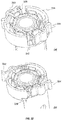
- the annular locking ring or bezel 106 has an inner circumferential surface 126, opposing first and second axial surfaces 128 and 130 and an outer circumferential surface 132.
- a first set of circumferentially equidistantly arranged teeth 134 is protruding radially inward from the inner circumferential surface 126 at the first axial surface end 128 (i.e. the end facing away from the coupling portion 114 during assembly) and a second set of circumferentially equidistantly arranged teeth 136 is protruding axially from the second axial surface 130 and radially inward at the teeth's end.
- First set of teeth 134 are angularly offset from the second set of teeth 136.
- Each set of teeth 134, 136 are circumferentially equidistantly spaced so as to align with the gaps between the retainers 118.
- the second set of teeth 138 may comprise a front surface that is chamfered towards the coupling portion 114 and protrusions 112 of the bushing 102 during assembly.
- the outer circumferential surface 132 may be provided with corrugations, one or more slots or axial grooves, so as to optimise gripping properties when handling the locking ring during assembly, but also to provide an alignment guide that is adapted to matingly engage with the anti-rotational stopper 119 of the support bracket 104 so as to avoid accidental rotation during assembly.
- the corrugations are all the same thus the locking and unlocking force required to overcome the anti-rotational stopper 119 is the same irrespective of the position of the bezel 106. In this way, if the operator finds the unlocking handle difficult to reach when it is positioned, s/he can easily change the angular alignment it in order to reach it better.
- Figure 6 shows an exploded view of the three modular components, i.e. bushing 102, support bracket 104 and locking ring 106 before assembly with the bushing 102 mounted to a wall structure 200.
- a bushing 102 is mounted to a wall structure with a fastener 108 (e.g. bolt).
- the second set of teeth 136 of the locking ring 106 is then brought into alignment with the gaps between the retainers 118 and pushed through until the first set of teeth 134 abuts with the rear end of the retainers 118.
- the locking ring 106 is rotated clockwise, using a handle portion 140, until the first set of teeth 134 is brought into alignment with the retainer 118 gaps, also moving the second set of teeth 136 adjacent to the dent portion 120 of the retainers 118.
- the anti-rotational stopper 119 may be used with a predetermined corrugation, slot or groove provided on the locking ring 106.
- the coupled support bracket 104 and locking ring 106 are now “primed” and can be slidingly mounted onto the bushing 102, wherein two adjacent protrusion 112 are received by the dent portion 120 and the gap, respectively.
- the support bracket 104 is "locked” onto the bushing 102 by rotating the locking ring 106 or bezel anticlockwise until the second set of teeth 136 abuts against a radial (side) wall of the retainers 118 blocking the dent portion 120 containing the protrusion 112.
- the support bracket 104 is axially, as well as, rotationally immovable with respect to the bushing 102, thus, providing a strong retention and precise angular alignment.
- the required angle of rotation is about 10°.
- the support bracket 104 is "locked" onto the bushing 102 by rotating the locking ring 106 or bezel clockwise until the second set of teeth 136 abuts against a radial (side) wall of the retainers 118 blocking the dent portion 120 containing the protrusion 112.
- the locking ring 106 is simply moved clockwise (e.g. 10° for this particular example) "unlocking" the coupling between the support bracket 104 and the bushing 102.
- the coupled support bracket 104 and locking ring 106 can be slidingly (axially) moved off the bushing 102, re-orientated or replaced, and slidingly moved back onto the bushing 102 before the locking ring 106 is rotated back anticlockwise to "lock" the coupling between the support bracket 104 and the bushing 102.
- the assemble/disassemble, mount/demount process can be repeated without the risk of damaging the bracket assembly 100 or injuring the user.
- Figures 9 (a) and (b) shows a number of tightly spaced bracket assemblies 100 with various designs of the bracket support 104 mounted to a wall structure 200 emphasising the minimal space required to assemble and mount the bracket assembly 100 of the present invention.
- the locking ring 106 or bezel can be positioned around the perimeter of the coupling portion 114 in the most suitable (or convenient) position for the user.
- the bracket assemblies 100 do not interfere with each other (e.g. interfering handle portions 140) when mounted on the bolt spacer joint.
- an alternative bracket assembly 300 includes a bushing or base 302 and a support bracket 304, operably coupleable and removably mountable to a wall structure.
- the bushing 302 includes a cylindrical body having a bore 306 configured to receive a bolt or fastener 308 for attachment to a wall structure.
- the cylindrical outer surface 311 of the bushing 302 is provided with a number of oblong protrusions 312 or ribs extending radially outward from the outer circumferential surface 311.
- the bushing comprises eighteen protrusions 312 that are equidistantly arranged on the outer circumferential surface 311, however, it is understood that any other suitable number of protrusions 312 may be used.
- the support bracket 304 includes an annular coupling portion 314 perpendicular extending from a support portion 316 of the support bracket 304. It is understood that the support portion 316 may be of any suitable shape or design. Also, the coupling portion 314 may extend from the support portion 316 at any suitable orientation relative to the longitudinal axis of the support portion 316.
- the annular coupling portion 314 includes a number of clipping hooks 318 circumferentially spaced apart on an inner circumferential surface 320 of the coupling portion 314. The clipping hooks 318 are suitably flexible to allow radial movement during assembly.
- First and second hinged lever 322, 324 are provided in opposing circumferential gaps between the clipping hooks 318 on the inner circumferential surface 320 of the coupling portion 314.
- Each one of the first and second lever 322, 324 comprises a tongue 326 configured move to and fit in between the gaps provided by adjacent spaced apart protrusions 312 of the bushing 302.
- the first and second levers 322, 324 are connected to the coupling portion 314 via a bending hinge, allowing levers 322, 324 to move between an "unlocked” position, with the tongue 326 moved away from the gap between adjacent protrusions 312, and a "locked” position, with the tongue 326 moved into the gap between adjacent protrusions 312.
- first and second levers 322, 324 are adapted to be retained in the "locked” and "unlocked” position by a lip 328.
- the coupling portion 314 is slidingly moved onto the bushing 302 until the clipping hooks 318 fixingly engage with the protrusions 312.
- the support bracket 304 is axially immovable but rotationally movable with respect to the bushing 302.
- the bracket assembly 300 is rotationally “locked” by pushing first and second lever 322, 324 into the gap between the protrusions 312, and the first and second levers 322, 324 are retained in this position by the lip 328.
- the user simply "unlocks” the bracket assembly 300 by moving first and second lever 322, 324 into the "unlocked” position overcoming the lip 328 with a suitable force.
- the support bracket 304 is then be rotated into the desired angular orientation and first and second levers 322, 324 are moved back into the "locked” position.
- the alternative bracket assembly 300 provides the advantage of easy rotational adjustment even after it is mounted to the bushing 302.
Landscapes
- Engineering & Computer Science (AREA)
- General Engineering & Computer Science (AREA)
- Mechanical Engineering (AREA)
- Connection Of Plates (AREA)
Priority Applications (2)
| Application Number | Priority Date | Filing Date | Title |
|---|---|---|---|
| EP19177053.6A EP3744989B1 (de) | 2019-05-28 | 2019-05-28 | Modulares verbindungsteil |
| PCT/US2020/029050 WO2020242644A1 (en) | 2019-05-28 | 2020-04-21 | A bracket assembly |
Applications Claiming Priority (1)
| Application Number | Priority Date | Filing Date | Title |
|---|---|---|---|
| EP19177053.6A EP3744989B1 (de) | 2019-05-28 | 2019-05-28 | Modulares verbindungsteil |
Publications (2)
| Publication Number | Publication Date |
|---|---|
| EP3744989A1 true EP3744989A1 (de) | 2020-12-02 |
| EP3744989B1 EP3744989B1 (de) | 2023-10-04 |
Family
ID=66857616
Family Applications (1)
| Application Number | Title | Priority Date | Filing Date |
|---|---|---|---|
| EP19177053.6A Active EP3744989B1 (de) | 2019-05-28 | 2019-05-28 | Modulares verbindungsteil |
Country Status (2)
| Country | Link |
|---|---|
| EP (1) | EP3744989B1 (de) |
| WO (1) | WO2020242644A1 (de) |
Citations (8)
| Publication number | Priority date | Publication date | Assignee | Title |
|---|---|---|---|---|
| GB1011688A (en) * | 1962-07-24 | 1965-12-01 | Witanda Engineering Ltd | A tube jointing device |
| EP0221375A1 (de) * | 1985-10-30 | 1987-05-13 | Neiman | Schliesszylinder zum bajonettartigen Einbau |
| US20060280553A1 (en) * | 2005-06-08 | 2006-12-14 | Anthony Paul G | Shaft coupler |
| WO2008074066A1 (en) * | 2006-12-19 | 2008-06-26 | Gesswein, Andreas Klaus | A set of components able to be coupled together |
| US9086087B1 (en) * | 2013-12-09 | 2015-07-21 | Charles Scott Sharman | Multi-force resistant mechanical joint |
| WO2017095224A1 (en) * | 2015-12-02 | 2017-06-08 | Mci (Mirror Controls International) Netherlands B.V. | Fastening construction, in particular for an exterior vision unit of a motor vehicle |
| WO2017126113A1 (ja) * | 2016-01-22 | 2017-07-27 | 株式会社パトライト | 取付具 |
| DE102017010602A1 (de) * | 2017-11-16 | 2019-05-16 | A. Raymond Et Cie | Befestiger |
-
2019
- 2019-05-28 EP EP19177053.6A patent/EP3744989B1/de active Active
-
2020
- 2020-04-21 WO PCT/US2020/029050 patent/WO2020242644A1/en active Application Filing
Patent Citations (8)
| Publication number | Priority date | Publication date | Assignee | Title |
|---|---|---|---|---|
| GB1011688A (en) * | 1962-07-24 | 1965-12-01 | Witanda Engineering Ltd | A tube jointing device |
| EP0221375A1 (de) * | 1985-10-30 | 1987-05-13 | Neiman | Schliesszylinder zum bajonettartigen Einbau |
| US20060280553A1 (en) * | 2005-06-08 | 2006-12-14 | Anthony Paul G | Shaft coupler |
| WO2008074066A1 (en) * | 2006-12-19 | 2008-06-26 | Gesswein, Andreas Klaus | A set of components able to be coupled together |
| US9086087B1 (en) * | 2013-12-09 | 2015-07-21 | Charles Scott Sharman | Multi-force resistant mechanical joint |
| WO2017095224A1 (en) * | 2015-12-02 | 2017-06-08 | Mci (Mirror Controls International) Netherlands B.V. | Fastening construction, in particular for an exterior vision unit of a motor vehicle |
| WO2017126113A1 (ja) * | 2016-01-22 | 2017-07-27 | 株式会社パトライト | 取付具 |
| DE102017010602A1 (de) * | 2017-11-16 | 2019-05-16 | A. Raymond Et Cie | Befestiger |
Also Published As
| Publication number | Publication date |
|---|---|
| WO2020242644A1 (en) | 2020-12-03 |
| EP3744989B1 (de) | 2023-10-04 |
Similar Documents
| Publication | Publication Date | Title |
|---|---|---|
| US7208853B2 (en) | Fastener assembly | |
| US20050015928A1 (en) | Caster assembly | |
| US4488778A (en) | Exterior rear-view automobile mirror | |
| JP2005201439A (ja) | 軌道溝用締結具 | |
| US7131705B1 (en) | Wheel hub cover | |
| EP1350712A2 (de) | Anordnung zur Anbringung einer Abdeckung an die Unterseite eines Bodenblechs eines Kraftfahrzeuges | |
| JP2014503773A (ja) | 自動ロック機構ならびにその固定および固定解除機構 | |
| EP3919762B1 (de) | Befestigungsmittel | |
| EP3744989B1 (de) | Modulares verbindungsteil | |
| US20140173880A1 (en) | Accessory mounting apparatus for a vehicle | |
| US6733061B1 (en) | Method and apparatus for installing a stowage cabinet in a motor vehicle | |
| EP4105109B1 (de) | Kotflügeleinheit für kraftfahrzeuge | |
| US9073416B2 (en) | Adjustable bail arm coupling | |
| WO2010089709A1 (en) | Article to fix on a support provided with an opening and assist grip handle comprising it | |
| EP3816464A1 (de) | Schraubkappe | |
| CN112392838A (zh) | 螺栓紧固件 | |
| EP3889447A1 (de) | Befestigungsmittel | |
| CN217705932U (zh) | 一种基于汽车转向柱管总成上的安装结构 | |
| US11926289B2 (en) | Bicycle rack with assembly features | |
| EP3789621B1 (de) | Abstandshalteranordnung | |
| JPS5853506Y2 (ja) | 管継手離脱防止用金具 | |
| EP3925833A1 (de) | Befestigungsclip | |
| WO2022239037A1 (en) | Device with adaptable elements, suitable for fastening boxes, components or other accessories to the frame of heavy vehicles | |
| CN215847934U (zh) | 安装和拆卸工具 | |
| CN212685427U (zh) | 随车物品拆装结构和具有其的车辆 |
Legal Events
| Date | Code | Title | Description |
|---|---|---|---|
| PUAI | Public reference made under article 153(3) epc to a published international application that has entered the european phase |
Free format text: ORIGINAL CODE: 0009012 |
|
| STAA | Information on the status of an ep patent application or granted ep patent |
Free format text: STATUS: THE APPLICATION HAS BEEN PUBLISHED |
|
| AK | Designated contracting states |
Kind code of ref document: A1 Designated state(s): AL AT BE BG CH CY CZ DE DK EE ES FI FR GB GR HR HU IE IS IT LI LT LU LV MC MK MT NL NO PL PT RO RS SE SI SK SM TR |
|
| AX | Request for extension of the european patent |
Extension state: BA ME |
|
| STAA | Information on the status of an ep patent application or granted ep patent |
Free format text: STATUS: REQUEST FOR EXAMINATION WAS MADE |
|
| 17P | Request for examination filed |
Effective date: 20210429 |
|
| RBV | Designated contracting states (corrected) |
Designated state(s): AL AT BE BG CH CY CZ DE DK EE ES FI FR GB GR HR HU IE IS IT LI LT LU LV MC MK MT NL NO PL PT RO RS SE SI SK SM TR |
|
| GRAP | Despatch of communication of intention to grant a patent |
Free format text: ORIGINAL CODE: EPIDOSNIGR1 |
|
| STAA | Information on the status of an ep patent application or granted ep patent |
Free format text: STATUS: GRANT OF PATENT IS INTENDED |
|
| INTG | Intention to grant announced |
Effective date: 20230526 |
|
| P01 | Opt-out of the competence of the unified patent court (upc) registered |
Effective date: 20230606 |
|
| GRAS | Grant fee paid |
Free format text: ORIGINAL CODE: EPIDOSNIGR3 |
|
| GRAA | (expected) grant |
Free format text: ORIGINAL CODE: 0009210 |
|
| STAA | Information on the status of an ep patent application or granted ep patent |
Free format text: STATUS: THE PATENT HAS BEEN GRANTED |
|
| AK | Designated contracting states |
Kind code of ref document: B1 Designated state(s): AL AT BE BG CH CY CZ DE DK EE ES FI FR GB GR HR HU IE IS IT LI LT LU LV MC MK MT NL NO PL PT RO RS SE SI SK SM TR |
|
| REG | Reference to a national code |
Ref country code: GB Ref legal event code: FG4D |
|
| REG | Reference to a national code |
Ref country code: CH Ref legal event code: EP |
|
| REG | Reference to a national code |
Ref country code: IE Ref legal event code: FG4D |
|
| REG | Reference to a national code |
Ref country code: DE Ref legal event code: R096 Ref document number: 602019038499 Country of ref document: DE |
|
| REG | Reference to a national code |
Ref country code: LT Ref legal event code: MG9D |
|
| REG | Reference to a national code |
Ref country code: NL Ref legal event code: MP Effective date: 20231004 |
|
| REG | Reference to a national code |
Ref country code: AT Ref legal event code: MK05 Ref document number: 1618025 Country of ref document: AT Kind code of ref document: T Effective date: 20231004 |
|
| PG25 | Lapsed in a contracting state [announced via postgrant information from national office to epo] |
Ref country code: NL Free format text: LAPSE BECAUSE OF FAILURE TO SUBMIT A TRANSLATION OF THE DESCRIPTION OR TO PAY THE FEE WITHIN THE PRESCRIBED TIME-LIMIT Effective date: 20231004 |
|
| PG25 | Lapsed in a contracting state [announced via postgrant information from national office to epo] |
Ref country code: GR Free format text: LAPSE BECAUSE OF FAILURE TO SUBMIT A TRANSLATION OF THE DESCRIPTION OR TO PAY THE FEE WITHIN THE PRESCRIBED TIME-LIMIT Effective date: 20240105 |
|
| PG25 | Lapsed in a contracting state [announced via postgrant information from national office to epo] |
Ref country code: IS Free format text: LAPSE BECAUSE OF FAILURE TO SUBMIT A TRANSLATION OF THE DESCRIPTION OR TO PAY THE FEE WITHIN THE PRESCRIBED TIME-LIMIT Effective date: 20240204 |
|
| PG25 | Lapsed in a contracting state [announced via postgrant information from national office to epo] |
Ref country code: LT Free format text: LAPSE BECAUSE OF FAILURE TO SUBMIT A TRANSLATION OF THE DESCRIPTION OR TO PAY THE FEE WITHIN THE PRESCRIBED TIME-LIMIT Effective date: 20231004 |
|
| PG25 | Lapsed in a contracting state [announced via postgrant information from national office to epo] |
Ref country code: AT Free format text: LAPSE BECAUSE OF FAILURE TO SUBMIT A TRANSLATION OF THE DESCRIPTION OR TO PAY THE FEE WITHIN THE PRESCRIBED TIME-LIMIT Effective date: 20231004 |
|
| PG25 | Lapsed in a contracting state [announced via postgrant information from national office to epo] |
Ref country code: ES Free format text: LAPSE BECAUSE OF FAILURE TO SUBMIT A TRANSLATION OF THE DESCRIPTION OR TO PAY THE FEE WITHIN THE PRESCRIBED TIME-LIMIT Effective date: 20231004 |
|
| PG25 | Lapsed in a contracting state [announced via postgrant information from national office to epo] |
Ref country code: LT Free format text: LAPSE BECAUSE OF FAILURE TO SUBMIT A TRANSLATION OF THE DESCRIPTION OR TO PAY THE FEE WITHIN THE PRESCRIBED TIME-LIMIT Effective date: 20231004 Ref country code: IS Free format text: LAPSE BECAUSE OF FAILURE TO SUBMIT A TRANSLATION OF THE DESCRIPTION OR TO PAY THE FEE WITHIN THE PRESCRIBED TIME-LIMIT Effective date: 20240204 Ref country code: GR Free format text: LAPSE BECAUSE OF FAILURE TO SUBMIT A TRANSLATION OF THE DESCRIPTION OR TO PAY THE FEE WITHIN THE PRESCRIBED TIME-LIMIT Effective date: 20240105 Ref country code: ES Free format text: LAPSE BECAUSE OF FAILURE TO SUBMIT A TRANSLATION OF THE DESCRIPTION OR TO PAY THE FEE WITHIN THE PRESCRIBED TIME-LIMIT Effective date: 20231004 Ref country code: BG Free format text: LAPSE BECAUSE OF FAILURE TO SUBMIT A TRANSLATION OF THE DESCRIPTION OR TO PAY THE FEE WITHIN THE PRESCRIBED TIME-LIMIT Effective date: 20240104 Ref country code: AT Free format text: LAPSE BECAUSE OF FAILURE TO SUBMIT A TRANSLATION OF THE DESCRIPTION OR TO PAY THE FEE WITHIN THE PRESCRIBED TIME-LIMIT Effective date: 20231004 Ref country code: PT Free format text: LAPSE BECAUSE OF FAILURE TO SUBMIT A TRANSLATION OF THE DESCRIPTION OR TO PAY THE FEE WITHIN THE PRESCRIBED TIME-LIMIT Effective date: 20240205 |