EP3744986A1 - Hydrostatic pressure cylinder - Google Patents
Hydrostatic pressure cylinder Download PDFInfo
- Publication number
- EP3744986A1 EP3744986A1 EP18903004.2A EP18903004A EP3744986A1 EP 3744986 A1 EP3744986 A1 EP 3744986A1 EP 18903004 A EP18903004 A EP 18903004A EP 3744986 A1 EP3744986 A1 EP 3744986A1
- Authority
- EP
- European Patent Office
- Prior art keywords
- cylinder tube
- fluid pressure
- magnet
- pressure cylinder
- cover
- Prior art date
- Legal status (The legal status is an assumption and is not a legal conclusion. Google has not performed a legal analysis and makes no representation as to the accuracy of the status listed.)
- Withdrawn
Links
- 230000002706 hydrostatic effect Effects 0.000 title abstract description 3
- 239000012530 fluid Substances 0.000 claims description 71
- 230000007246 mechanism Effects 0.000 claims description 14
- 238000012856 packing Methods 0.000 description 27
- 238000009434 installation Methods 0.000 description 15
- 239000007769 metal material Substances 0.000 description 5
- 230000000694 effects Effects 0.000 description 4
- 239000000463 material Substances 0.000 description 4
- 230000004048 modification Effects 0.000 description 4
- 238000012986 modification Methods 0.000 description 4
- 229910000838 Al alloy Inorganic materials 0.000 description 2
- 230000007423 decrease Effects 0.000 description 2
- 229920001971 elastomer Polymers 0.000 description 2
- 239000002783 friction material Substances 0.000 description 2
- 229920001343 polytetrafluoroethylene Polymers 0.000 description 2
- 239000004810 polytetrafluoroethylene Substances 0.000 description 2
- 229910000975 Carbon steel Inorganic materials 0.000 description 1
- 229910000831 Steel Inorganic materials 0.000 description 1
- 230000004323 axial length Effects 0.000 description 1
- 239000010962 carbon steel Substances 0.000 description 1
- 230000006835 compression Effects 0.000 description 1
- 238000007906 compression Methods 0.000 description 1
- 239000000470 constituent Substances 0.000 description 1
- 238000006073 displacement reaction Methods 0.000 description 1
- 239000013013 elastic material Substances 0.000 description 1
- 239000000806 elastomer Substances 0.000 description 1
- 230000005389 magnetism Effects 0.000 description 1
- 238000005192 partition Methods 0.000 description 1
- -1 polytetrafluoroethylene Polymers 0.000 description 1
- 229910052761 rare earth metal Inorganic materials 0.000 description 1
- 150000002910 rare earth metals Chemical class 0.000 description 1
- 229920005989 resin Polymers 0.000 description 1
- 239000011347 resin Substances 0.000 description 1
- 239000010935 stainless steel Substances 0.000 description 1
- 229910001256 stainless steel alloy Inorganic materials 0.000 description 1
- 239000010959 steel Substances 0.000 description 1
- 229920003002 synthetic resin Polymers 0.000 description 1
- 239000000057 synthetic resin Substances 0.000 description 1
- 229910000859 α-Fe Inorganic materials 0.000 description 1
Images



Classifications
-
- F—MECHANICAL ENGINEERING; LIGHTING; HEATING; WEAPONS; BLASTING
- F15—FLUID-PRESSURE ACTUATORS; HYDRAULICS OR PNEUMATICS IN GENERAL
- F15B—SYSTEMS ACTING BY MEANS OF FLUIDS IN GENERAL; FLUID-PRESSURE ACTUATORS, e.g. SERVOMOTORS; DETAILS OF FLUID-PRESSURE SYSTEMS, NOT OTHERWISE PROVIDED FOR
- F15B15/00—Fluid-actuated devices for displacing a member from one position to another; Gearing associated therewith
- F15B15/20—Other details, e.g. assembly with regulating devices
- F15B15/28—Means for indicating the position, e.g. end of stroke
-
- F—MECHANICAL ENGINEERING; LIGHTING; HEATING; WEAPONS; BLASTING
- F15—FLUID-PRESSURE ACTUATORS; HYDRAULICS OR PNEUMATICS IN GENERAL
- F15B—SYSTEMS ACTING BY MEANS OF FLUIDS IN GENERAL; FLUID-PRESSURE ACTUATORS, e.g. SERVOMOTORS; DETAILS OF FLUID-PRESSURE SYSTEMS, NOT OTHERWISE PROVIDED FOR
- F15B15/00—Fluid-actuated devices for displacing a member from one position to another; Gearing associated therewith
- F15B15/08—Characterised by the construction of the motor unit
- F15B15/14—Characterised by the construction of the motor unit of the straight-cylinder type
- F15B15/1423—Component parts; Constructional details
- F15B15/1447—Pistons; Piston to piston rod assemblies
-
- F—MECHANICAL ENGINEERING; LIGHTING; HEATING; WEAPONS; BLASTING
- F15—FLUID-PRESSURE ACTUATORS; HYDRAULICS OR PNEUMATICS IN GENERAL
- F15B—SYSTEMS ACTING BY MEANS OF FLUIDS IN GENERAL; FLUID-PRESSURE ACTUATORS, e.g. SERVOMOTORS; DETAILS OF FLUID-PRESSURE SYSTEMS, NOT OTHERWISE PROVIDED FOR
- F15B15/00—Fluid-actuated devices for displacing a member from one position to another; Gearing associated therewith
- F15B15/20—Other details, e.g. assembly with regulating devices
- F15B15/28—Means for indicating the position, e.g. end of stroke
- F15B15/2815—Position sensing, i.e. means for continuous measurement of position, e.g. LVDT
- F15B15/2861—Position sensing, i.e. means for continuous measurement of position, e.g. LVDT using magnetic means
-
- F—MECHANICAL ENGINEERING; LIGHTING; HEATING; WEAPONS; BLASTING
- F15—FLUID-PRESSURE ACTUATORS; HYDRAULICS OR PNEUMATICS IN GENERAL
- F15B—SYSTEMS ACTING BY MEANS OF FLUIDS IN GENERAL; FLUID-PRESSURE ACTUATORS, e.g. SERVOMOTORS; DETAILS OF FLUID-PRESSURE SYSTEMS, NOT OTHERWISE PROVIDED FOR
- F15B15/00—Fluid-actuated devices for displacing a member from one position to another; Gearing associated therewith
- F15B15/08—Characterised by the construction of the motor unit
- F15B15/14—Characterised by the construction of the motor unit of the straight-cylinder type
-
- F—MECHANICAL ENGINEERING; LIGHTING; HEATING; WEAPONS; BLASTING
- F15—FLUID-PRESSURE ACTUATORS; HYDRAULICS OR PNEUMATICS IN GENERAL
- F15B—SYSTEMS ACTING BY MEANS OF FLUIDS IN GENERAL; FLUID-PRESSURE ACTUATORS, e.g. SERVOMOTORS; DETAILS OF FLUID-PRESSURE SYSTEMS, NOT OTHERWISE PROVIDED FOR
- F15B15/00—Fluid-actuated devices for displacing a member from one position to another; Gearing associated therewith
- F15B15/08—Characterised by the construction of the motor unit
- F15B15/14—Characterised by the construction of the motor unit of the straight-cylinder type
- F15B15/1414—Characterised by the construction of the motor unit of the straight-cylinder type with non-rotatable piston
-
- F—MECHANICAL ENGINEERING; LIGHTING; HEATING; WEAPONS; BLASTING
- F15—FLUID-PRESSURE ACTUATORS; HYDRAULICS OR PNEUMATICS IN GENERAL
- F15B—SYSTEMS ACTING BY MEANS OF FLUIDS IN GENERAL; FLUID-PRESSURE ACTUATORS, e.g. SERVOMOTORS; DETAILS OF FLUID-PRESSURE SYSTEMS, NOT OTHERWISE PROVIDED FOR
- F15B15/00—Fluid-actuated devices for displacing a member from one position to another; Gearing associated therewith
- F15B15/08—Characterised by the construction of the motor unit
- F15B15/14—Characterised by the construction of the motor unit of the straight-cylinder type
- F15B15/1423—Component parts; Constructional details
- F15B15/1438—Cylinder to end cap assemblies
-
- F—MECHANICAL ENGINEERING; LIGHTING; HEATING; WEAPONS; BLASTING
- F15—FLUID-PRESSURE ACTUATORS; HYDRAULICS OR PNEUMATICS IN GENERAL
- F15B—SYSTEMS ACTING BY MEANS OF FLUIDS IN GENERAL; FLUID-PRESSURE ACTUATORS, e.g. SERVOMOTORS; DETAILS OF FLUID-PRESSURE SYSTEMS, NOT OTHERWISE PROVIDED FOR
- F15B15/00—Fluid-actuated devices for displacing a member from one position to another; Gearing associated therewith
- F15B15/20—Other details, e.g. assembly with regulating devices
- F15B15/26—Locking mechanisms
-
- F—MECHANICAL ENGINEERING; LIGHTING; HEATING; WEAPONS; BLASTING
- F15—FLUID-PRESSURE ACTUATORS; HYDRAULICS OR PNEUMATICS IN GENERAL
- F15B—SYSTEMS ACTING BY MEANS OF FLUIDS IN GENERAL; FLUID-PRESSURE ACTUATORS, e.g. SERVOMOTORS; DETAILS OF FLUID-PRESSURE SYSTEMS, NOT OTHERWISE PROVIDED FOR
- F15B15/00—Fluid-actuated devices for displacing a member from one position to another; Gearing associated therewith
- F15B15/20—Other details, e.g. assembly with regulating devices
- F15B15/28—Means for indicating the position, e.g. end of stroke
- F15B15/2807—Position switches, i.e. means for sensing of discrete positions only, e.g. limit switches
-
- F—MECHANICAL ENGINEERING; LIGHTING; HEATING; WEAPONS; BLASTING
- F15—FLUID-PRESSURE ACTUATORS; HYDRAULICS OR PNEUMATICS IN GENERAL
- F15B—SYSTEMS ACTING BY MEANS OF FLUIDS IN GENERAL; FLUID-PRESSURE ACTUATORS, e.g. SERVOMOTORS; DETAILS OF FLUID-PRESSURE SYSTEMS, NOT OTHERWISE PROVIDED FOR
- F15B15/00—Fluid-actuated devices for displacing a member from one position to another; Gearing associated therewith
- F15B15/20—Other details, e.g. assembly with regulating devices
- F15B15/28—Means for indicating the position, e.g. end of stroke
- F15B15/2892—Means for indicating the position, e.g. end of stroke characterised by the attachment means
Definitions
- the present invention relates to a fluid pressure cylinder (hydrostatic pressure cylinder) including a piston on which a magnet is disposed.
- a typical fluid pressure cylinder includes a cylinder tube, a piston disposed inside the cylinder tube to be movable in the axial direction, and a piston rod connected to the piston.
- a ring-shaped magnet is attached to an outer circumferential part of a piston, and a magnetic sensor is disposed outside a cylinder tube to detect the position of the piston.
- the magnet has a ring shape and generates a magnetic field around the entire circumference while the magnetic sensor is disposed on the cylinder tube only at a point in the circumferential direction. That is, the magnet occupies a volume more than necessary to detect the position of the piston.
- magnets contain scarce resources, it is preferable that the magnets be reduced in size in view of saving resources.
- the fluid pressure cylinder is installed inside various instruments including carrying units before use, and the magnetic sensor installed outside the cylinder may become an obstacle depending on the layout of surrounding parts. Thus, there is a need for flexibility in changing the position of the magnetic sensor installed around the fluid pressure cylinder.
- the installation position of the magnetic sensor is unfavorably limited by the position of the magnet since the magnetic sensor needs to be disposed close to the magnet.
- the present invention has the object of providing a fluid pressure cylinder allowing the installation position of a magnetic sensor to be changed flexibly even with a magnet reduced in size.
- a fluid pressure cylinder comprises a cylinder tube including a slide hole with a circular shape inside the cylinder tube, a piston unit disposed to be reciprocable along the slide hole, a piston rod protruding from the piston unit in an axial direction, a magnet having a size corresponding to part of the piston unit in a circumferential direction, a holding member that includes a magnet holding portion configured to hold the magnet and that is attached to the piston unit, a rotation restriction structure configured to restrict rotation of the holding member relative to the cylinder tube, a first cover attached adjacent to one end of the cylinder tube, and a second cover attached adjacent to another end of the cylinder tube, wherein the cylinder tube is rotatable in the circumferential direction relative to the first and second covers, and the cylinder tube is provided with a positioning portion enabling a circumferential position of the cylinder tube to be fixed with respect to the first and second covers.
- the holding member holding the magnet is assembled to co-rotate with the cylinder tube by the rotation restriction structure, and the cylinder tube is installed to be rotatable relative to the first and second covers. Consequently, when the first and second covers are assembled to an instrument to be used, the orientation of the cylinder tube can be rotated so that a magnetic sensor can be disposed in a desired position. As a result, installation of the fluid pressure cylinder is simplified.
- the positioning portion may include a protrusion or a groove provided in an outer circumferential part of the cylinder tube, and a sensor fixing member configured to hold a magnetic sensor may be engaged with the protrusion or the groove to fix the circumferential position of the cylinder tube with respect to the first and second covers.
- the circumferential position of the cylinder tube can be fixed by engaging the sensor fixing member with the protrusion or the groove provided in the outer circumferential part of the cylinder tube, resulting in a simplified adjustment of the sensor installation position in the fluid pressure cylinder.
- an indicator portion configured to indicate a position of the magnet may be formed in the outer circumferential part of the cylinder tube.
- the positioning portion may function as the indicator portion. Since the position of the magnet is indicated by the indicator portion, the magnetic sensor can be installed in an appropriate position in the outer circumferential part of the cylinder tube.
- the positioning portion may be configured as a rail-like protrusion extending in the axial direction in the outer circumferential part of the cylinder tube.
- the sensor fixing member may include a base end portion fixed relative to the first and second covers, and a sensor holding portion disposed adjacent to the positioning portion, and the sensor holding portion may be engaged with the positioning portion to position the cylinder tube in the circumferential direction. Since the sensor fixing member also functions as the positioning portion in this manner, the structure of the device is simplified.
- the above-described fluid pressure cylinder may further comprises a connecting rod passing through the first and second covers, a first securing mechanism configured to fix an axial position of the first cover with respect to the connecting rod, and a second securing mechanism configured to fix an axial position of the second cover with respect to the connecting rod, wherein the first and second securing mechanisms may secure the first and second covers to the cylinder tube without applying any axial load to the cylinder tube.
- the cylinder tube can be fixed to be rotatable relative to the first and second covers.
- the first securing mechanism may include a pair of first nuts screwed onto the connecting rod and configured to hold the first cover between the pair of first nuts in the axial direction
- the second securing mechanism may include a pair of second nuts screwed onto the connecting rod and configured to hold the second cover between the pair of second nuts in the axial direction.
- the first securing mechanism and the second securing mechanism can be achieved using a simple structure with nuts, and thus the structure can be simplified.
- the positioning portion may include set screws that pass through the cylinder tube in radial directions and that are in contact with the first and second covers. This enables the cylinder tube to be positioned in the circumferential direction.
- the cylinder tube may include a first narrowed portion engaged with the first cover, and a second narrowed portion engaged with the second cover, and the cylinder tube may be fixed to be rotatable relative to the first and second covers by the first and second narrowed portions.
- the cylinder tube can be fixed to be rotatable relative to the first and second covers.
- the holding member holding the magnet may be configured as a wear ring preventing the piston unit from coming into contact with the cylinder tube. Since the holding member is incorporated in the wear ring, the structure of the device is simplified, and the piston unit can be reduced in size and weight.
- the rotation restriction structure may include a detent groove formed in the slide hole and extending in the axial direction, and a detent protrusion formed in an outer circumferential part of the holding member and engaged with the detent groove.
- the installation position of the magnetic sensor can be changed flexibly even with the magnet reduced in size.
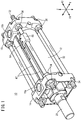
- a fluid pressure cylinder 10 according to a first embodiment illustrated in FIG. 1 includes a hollow tubular cylinder tube 12 having a circular slide hole 13 (cylinder chamber) inside the cylinder tube 12, a rod cover 14 (first cover) disposed at one end part of the cylinder tube 12, and a head cover 16 (second cover) disposed at another end part of the cylinder tube 12.
- the fluid pressure cylinder 10 further includes a piston unit 18 disposed inside the cylinder tube 12 to be movable in the axial direction (X direction), and a piston rod 20 connected to the piston unit 18.
- the fluid pressure cylinder 10 is used as an actuator for, for example, carrying a workpiece.
- the cylinder tube 12 is a tubular body made of, for example, a metal material such as aluminum alloy and extends in the axial direction.
- the cylinder tube 12 has a hollow cylindrical shape.
- a detent groove 24 extends in the inner circumferential surface of the cylinder tube 12 in the axial direction of the cylinder tube 12.
- the detent groove 24 is tapered (into a trapezoidal shape or a triangular shape) such that the width (circumferential width) thereof decreases radially outward.
- the detent groove 24 may have other polygonal shapes (for example, quadrangular shape).
- the detent groove 24 is formed in the inner circumferential surface of the cylinder tube 12 at one point in the circumferential direction. Note that a plurality of (for example, two) detent grooves 24 may be formed in the inner circumferential surface of the cylinder tube 12 at a distance from each other in the circumferential direction.
- the rod cover 14 is a member made of, for example, a metal material similar to the material of the cylinder tube 12 and is provided to block up the one end part (an end part facing a direction of an arrow X1) of the cylinder tube 12.
- the rod cover 14 has a first port 15a.
- an annular protruding portion 14b provided for the rod cover 14 is fitted in the one end part of the cylinder tube 12.
- a packing 23 with a circular ring shape is disposed between the rod cover 14 and the cylinder tube 12.
- a packing 27 with a circular ring shape and a bush 25 with a circular ring shape are disposed in an inner circumferential part of the rod cover 14.
- the head cover 16 is a member made of, for example, a metal material similar to the material of the cylinder tube 12 and is provided to block up the other end part (an end part facing a direction of an arrow X2) of the cylinder tube 12.
- the head cover 16 has a second port 15b.
- An annular protruding portion 16b provided for the head cover 16 is fitted in the other end part of the cylinder tube 12.
- a packing 31 with a circular ring shape is disposed between the head cover 16 and the cylinder tube 12.
- the cylinder tube 12, the rod cover 14, and the head cover 16 are connected to each other in the axial direction by a plurality of connecting rods 32 and nuts 34 and 36.
- the plurality of pairs of connecting rods 32 are disposed at intervals in the circumferential direction.
- the connecting rods 32 pass through the rod cover 14 and head cover 16.
- the rod cover 14 is fastened while being held between the nuts 34 (first nuts) from both sides in the axial direction. This secures the rod cover 14 in the axial direction of the connecting rods 32.
- the head cover 16 is fastened while being held between the nuts 36 (second nuts) from both sides in the axial direction. This secures the head cover 16 in the axial direction of the connecting rods 32.
- the nuts 34 constitute a first securing mechanism securing the rod cover 14 in the axial direction
- the nuts 36 constitute a second securing mechanism securing the head cover 16 in the axial direction.
- the piston unit 18 is accommodated inside the cylinder tube 12 (slide hole 13) to be slidable in the axial direction and partitions the inside of the slide hole 13 into a first pressure chamber 13a on the first port 15a side and a second pressure chamber 13b on the second port 15b side.
- the piston unit 18 is connected to a base end portion 20a of the piston rod 20.
- the piston unit 18 includes a circular piston body 40 protruding radially outward from the piston rod 20, a packing 42 with a circular ring shape attached to an outer circumferential part of the piston body 40, a magnet 46 disposed partially in the circumferential direction of the piston body 40, and a holding member 44 holding the magnet 46.
- the piston body 40 has a through-hole 40a passing therethrough in the axial direction.
- the base end portion 20a of the piston rod 20 is fitted in the through-hole 40a of the piston body 40 and secured to the piston body 40 by swaging.
- the piston rod 20 and the piston body 40 may be secured to each other by screwing instead of swaging.
- the piston body 40 and the piston rod 20 are preferably secured to each other to be rotatable in the circumferential direction.
- a packing receiving groove 50 and a magnet arrangement groove 52 are formed in the outer circumferential part of the piston body 40 in different axial positions.
- the packing receiving groove 50 and the magnet arrangement groove 52 each have a circular ring shape extending around the entire circumference in the circumferential direction.
- part of an outer circumferential part of the magnet arrangement groove 52 serves as a wear ring supporting surface 54 extending in the axial direction.
- the constituent material of the piston body 40 includes, for example, metal materials such as carbon steel, stainless steel, and aluminum alloy and hard resin.
- the packing 42 is a ring-shaped seal member made of an elastic material such as rubber or elastomer, and an O-ring, for example, can be used.
- the packing 42 is fitted in the packing receiving groove 50.
- the packing 42 is in contact with the inner circumferential surface of the cylinder tube 12 to be slidable. Specifically, the packing 42 is disposed in a space between the packing receiving groove 50 and the cylinder tube 12 while being elastically compressed, and an outer circumferential part of the packing 42 airtightly or fluid-tightly adheres to the inner circumferential surface of the slide hole 13 around the entire circumference. Moreover, the inner circumferential surface of the packing 42 airtightly or fluid-tightly adheres to the outer circumferential surface of the piston body 40 in the packing receiving groove 50.
- the packing 42 seals a gap between the outer circumferential surface of the piston unit 18 and the inner circumferential surface of the slide hole 13 to airtightly or fluid-tightly separate the first pressure chamber 13a and the second pressure chamber 13b from each other inside the slide hole 13.
- the detent groove 24 is formed in the inner circumferential surface of the cylinder tube 12.
- the detent groove 24 is filled up with part of the packing 42 expanding as the elastic compression is released at the detent groove 24.
- the packing 42 airtightly or fluid-tightly adheres to the detent groove 24.
- the packing 42 rotates together with the cylinder tube 12 or other part of the packing 42 expands and deforms depending on how the packing 42 is attached. In either case, the packing 42 is kept airtightly or fluid-tightly adhering to the detent groove 24.
- the packing 42 expands and deforms to fill up the detent grooves 24 at a plurality of points at intervals in the circumferential direction.
- the holding member 44 is attached to the piston body 40 to be rotatable. As a result, the holding member 44 is rotatable relative to the piston rod 20.
- the holding member 44 includes a circumferential portion 57 extending in the circumferential direction along the outer circumferential part of the piston body 40, and a magnet holding portion 58 protruding inward from the circumferential portion 57.
- the magnet holding portion 58 is disposed at one point in the circumferential direction.
- a plurality of magnet holding portions 58 may be disposed at intervals in the circumferential direction.
- the magnet holding portion 58 is fitted in the magnet arrangement groove 52 of the piston body 40.
- the magnet holding portion 58 has a through-hole part 58a passing through in the axial direction of the holding member 44.
- the magnet 46 is fitted and held in the through-hole part 58a.
- the magnet holding portion 58 protrudes radially inward from an inner circumferential surface 57c of the circumferential portion 57. More specifically, the magnet holding portion 58 is formed of a U-shaped frame part 58b protruding radially inward from the circumferential portion 57 and the through-hole part 58a, which is the inside of the frame part 58b. Thus, both ends of the magnet holding portion 58 in the axial direction are open, allowing the magnet 46 to be inserted in either direction.
- the axial dimension of the magnet holding portion 58 may be smaller than the axial dimension of the circumferential portion 57. In this case, the magnet holding portion 58 is disposed within the axial dimension of the circumferential portion 57.
- the holding member 44 is a wear ring 44A configured to prevent the piston body 40 from coming into contact with the cylinder tube 12, and is attached to the wear ring supporting surface 54.
- the wear ring 44A prevents the outer circumferential surface of the piston body 40 from coming into contact with the inner circumferential surface of the slide hole 13 when a large lateral load is applied to the piston unit 18 in a direction perpendicular to the axial direction while the fluid pressure cylinder 10 is in operation.
- the outer diameter of the wear ring 44A is greater than the outer diameter of the piston body 40.
- the wear ring 44A is made of a low friction material.
- the friction coefficient between the wear ring 44A and the inner circumferential surface of the slide hole 13 is smaller than the friction coefficient between the packing 42 and the inner circumferential surface of the slide hole 13.
- a low friction material includes, for example, synthetic resins with a low coefficient of friction and a high resistance to wear such as polytetrafluoroethylene (PTFE), and metal materials including, for example, bearing steel.
- the circumferential portion 57 is attached to the wear ring supporting surface 54 of the piston body 40.
- the circumferential portion 57 has a circular ring shape with a slit 57a (see FIG. 3 ) formed at a point in the circumferential direction.
- the slit 57a is formed in a position offset from the magnet holding portion 58 in the circumferential direction.
- the holding member 44 is forcibly expanded in radial directions and is disposed around the wear ring supporting surface 54.
- the holding member 44 is then attached to the magnet arrangement groove 52 and the wear ring supporting surface 54 as the diameter of the holding member 44 decreases by the elastic restoring force.
- the detent groove 24 is formed in the inner circumferential surface of the cylinder tube 12 in the axial direction of the cylinder tube 12, and a detent protrusion 60 engaged with the detent groove 24 is provided for the holding member 44.
- the detent groove 24 and the detent protrusion 60 constitute a rotation restriction structure.
- the detent protrusion 60 is slidable in the detent groove 24 in the axial direction.
- the detent protrusion 60 protrudes radially outward from an outer circumferential part of the holding member 44.
- the detent protrusion 60 is disposed on an outer circumferential surface 57b of the circumferential portion 57 in a position overlapping with the magnet holding portion 58 in the circumferential direction.
- the detent protrusion 60 extends on the circumferential portion 57 over the entire axial length of the circumferential portion 57.
- the detent protrusion 60 may be disposed in a position offset from the magnet holding portion 58 in the circumferential direction.
- the detent protrusion 60 has a shape similar to the shape of the detent groove 24. Moreover, in the case where the plurality of detent grooves 24 are formed in the inner circumferential surface of the cylinder tube 12 at intervals in the circumferential direction, a plurality of detent protrusions 60 may be disposed on the holding member 44 at intervals in the circumferential direction. In this case, the number of detent protrusions 60 may be the same as or less than the number of detent grooves 24.
- the magnet 46 has a non-ring shape, exists in the piston body 40 only at a point in the circumferential direction, and is fitted in the magnet holding portion 58. Although one magnet 46 is fitted in one magnet holding portion 58 in this embodiment, a configuration may be adopted in which a plurality of magnets 46 are used. An outer end 46a of the magnet 46 fitted in the magnet holding portion 58 opposes the inner circumferential surface of the cylinder tube 12.
- the magnet 46 is, for example, a ferrite magnet or a rare earth magnet.
- a magnetic sensor 64 is installed outside the cylinder tube 12. Specifically, a sensor bracket 66 (sensor fixing member) is attached to one of the connecting rods 32 illustrated in FIG. 1 . The magnetic sensor 64 is held by the sensor bracket 66. Thus, the position of the magnetic sensor 64 is fixed with respect to the head cover 16 and the rod cover 14 via the sensor bracket 66 and the connecting rod 32. The magnetic sensor 64 detects magnetism generated by the magnets 46 to detect the working position of the piston unit 18.
- the sensor bracket 66 includes a hook portion 66a with a curvature equal to the curvature of the outer circumferential surface of the connecting rod 32.
- the hook portion 66a is fitted onto the connecting rod 32 so that the sensor bracket 66 is secured to the connecting rod 32.
- an arm portion 66b extends from the hook portion 66a, and a sensor holding portion 66c is disposed at an end of the arm portion 66b to hold the magnetic sensor 64.
- the sensor holding portion 66c includes a contact part 66d that is brought into contact with the outer circumferential surface of the cylinder tube 12.
- the sensor bracket 66 of this embodiment is disposed close to rail-like protrusions 47 on an outer circumferential part of the cylinder tube 12.
- the rail-like protrusions 47 are disposed on the outer circumferential part of the cylinder tube 12, in a part adjacent to the magnet holding portion 58 in the circumferential direction.
- the part between the pair of rail-like protrusions 47 opposes the outer end 46a of the magnet 46.
- the contact part 66d of the sensor bracket 66 is fitted between the two rail-like protrusions 47 (groove).
- the two rail-like protrusions 47 (or the groove therebetween) constitute a positioning portion enabling the circumferential position of the cylinder tube 12 to be fixed with respect to the rod cover 14 and the head cover 16 (first and second covers).
- the rail-like protrusions 47 constitute an indicator portion indicating the position of the magnet 46.
- the sensor bracket 66 engaged with the rail-like protrusions 47 functions as the positioning portion that sets the circumferential position of the cylinder tube 12.
- the rail-like protrusions 47 are protrusions protruding radially outward from the cylinder tube 12 into shapes of rails and extend in the axial direction.
- the pair of rail-like protrusions 47 are disposed at a predetermined distance from each other in the circumferential direction. In a case where the circumferential distance (angular range) between the pair of rail-like protrusions 47 is larger than the angular range occupied by the circumferential dimension of the magnet 46, the rail-like protrusions 47 are disposed such that the middle of the gap between the pair of rail-like protrusions 47 coincides with the middle part of the magnet 46.
- the pair of rail-like protrusions 47 may be disposed in any positions within a range overlapping with the magnet 46. In this case, a plurality of pairs of rail-like protrusions 47 may be disposed.
- the indicator portion indicating the position of the magnet 46 is not limited to the rail-like protrusions 47 and may be formed of, for example, lines or grooves.
- the piston rod 20 is a columnar (circular cylindrical) member extending in the axial direction of the slide hole 13.
- the piston rod 20 passes through the rod cover 14.
- a workpiece fixing portion 20b of the piston rod 20 is exposed to the outside of the slide hole 13.
- the fluid pressure cylinder 10 is installed in, for example, instruments such as units for carrying workpieces and the like (actuators), and then the magnetic sensor 64 is installed on the cylinder tube 12 in an appropriate position depending on the layout of surrounding parts.
- instruments such as units for carrying workpieces and the like (actuators)
- the magnetic sensor 64 is installed on the cylinder tube 12 in an appropriate position depending on the layout of surrounding parts.
- a user can rotate the cylinder tube 12 with hands.
- a base end portion of the sensor bracket 66 is attached to the connecting rod 32 adjacent to the first and second ports 15a and 15b.
- the contact part 66d of the sensor bracket 66 is then fitted between the two rail-like protrusions 47 to install the magnetic sensor 64 in an appropriate position.
- the orientation of the sensor bracket 66 attached to the connecting rod 32 is changed depending on the circumferential position of the rail-like protrusions 47 so that the sensor bracket 66 can be engaged with the rail-like protrusions 47.
- the sensor bracket 66 can be attached to the other connecting rods 32.
- the attachment position of the sensor bracket 66 can be changed flexibly only by rotating the cylinder tube 12 with bare hands.
- the fluid pressure cylinder 10 described above operates as follows. In the description below, air serving as pressurized fluid is used. However, gas other than air may be used.
- pressurized fluid is supplied from a pressurized fluid supply source (not illustrated) to the second pressure chamber 13b via the second port 15b while the first port 15a is exposed to the atmosphere.
- a pressurized fluid supply source not illustrated
- the piston unit 18 is pushed by the pressurized fluid toward the rod cover 14.
- the piston unit 18 is displaced (advanced) toward the rod cover 14 together with the piston rod 20.
- pressurized fluid is supplied from the pressurized fluid supply source (not illustrated) to the first pressure chamber 13a via the first port 15a while the second port 15b is exposed to the atmosphere.
- the piston body 40 is pushed by the pressurized fluid toward the head cover 16.
- the piston unit 18 is displaced toward the head cover 16.
- the fluid pressure cylinder 10 according to the first embodiment produces the following effects.
- the magnet 46 is disposed only at the required point in the circumferential direction. This leads to resource savings on the material for the magnet.
- the holding member 44 is provided with the detent protrusion 60 configured to prevent the holding member 44 from rotating relative to the cylinder tube 12, thereby fixing the circumferential position of the magnet 46 with respect to the cylinder tube 12.
- the detent protrusion 60 configured to prevent the holding member 44 from rotating relative to the cylinder tube 12, thereby fixing the circumferential position of the magnet 46 with respect to the cylinder tube 12.
- the positioning portion enabling the circumferential position of the cylinder tube 12 to be fixed with respect to the rod cover 14 and the head cover 16 includes protrusions or a groove (the two rail-like protrusions 47 or the groove therebetween) provided in the outer circumferential part of the cylinder tube 12.
- the circumferential position of the cylinder tube 12 is fixed with respect to the rod cover 14 and the head cover 16 by engaging the sensor bracket 66 with the protrusions or the groove. This simple structure enables the circumferential position of the cylinder tube 12 to be fixed reliably.
- the cylinder tube 12 is provided with the rail-like protrusions 47 indicating the position of the magnet 46.
- the magnetic sensor 64 can be disposed in an appropriate position with respect to the magnet 46 by engaging the sensor bracket 66 holding the magnetic sensor 64 with the rail-like protrusions 47.
- the installation position of the magnetic sensor 64 can be changed flexibly by rotating the cylinder tube 12 after the fluid pressure cylinder 10 is installed in an instrument to be used.
- the installation position of the magnetic sensor 64 can be changed without loosening the mounting nuts of the connecting rods 32.
- the cylinder tube 12 can be positioned in the circumferential direction at the same time as installation of the magnetic sensor 64. Rotation of the cylinder tube 12 can be restricted without tightening the mounting nuts of the connecting rods 32.
- the holding member 44 is the wear ring 44A configured to prevent the piston body 40 from coming into contact with the cylinder tube 12.
- the holding member 44 serves both as the wear ring 44A and a member holding the magnet 46, leading to simplification of the structure.
- the fluid pressure cylinder 10 described above may be provided with a plurality of sensor brackets 66 holding the magnetic sensors 64.
- the magnetic sensor 64 for detecting the position of the piston unit 18 in the vicinity of the rod cover 14 and the magnetic sensor 64 for detecting the position of the piston unit 18 in the vicinity of the head cover 16 are attached to the two sensor brackets 66.
- One of the sensor brackets 66 is attached to be engaged with the pair of rail-like protrusions 47.
- the other sensor bracket 66 is attached to another connecting rod 32, and the sensor holding portion 66c of the other sensor bracket 66 is disposed close to the rail-like protrusions 47.
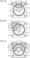
- the circumferential size (angular range) of the magnet 46 be increased so that the installation positions of the magnetic sensors 64 overlap with the magnet 46 as illustrated in FIG. 7A .
- the sensor brackets 66 can be disposed over two sides as illustrated in FIG. 7B , increasing flexibility in arranging the sensor brackets 66.
- a plurality of pairs of rail-like protrusions 47 may be disposed at a predetermined distance from each other in the circumferential direction.
- only one pair of rail-like protrusions 47 may be provided, and marks indicating the attachment positions of other sensor brackets 66 may be provided on the outer circumferential surface of the cylinder tube 12.
- the sensor brackets 66 can be disposed over three sides, that is, the side with the ports and the both sides thereof, as illustrated in FIG. 7C , further increasing flexibility in arranging the sensor brackets 66.
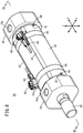
- a fluid pressure cylinder 80 includes a hollow tubular cylinder tube 82 having the circular slide hole 13 inside the cylinder tube 82, a rod cover 84 disposed at one end part of the cylinder tube 82, and a head cover 86 disposed at another end part of the cylinder tube 82.
- the fluid pressure cylinder 80 further includes the piston unit 18 disposed inside the cylinder tube 82 to be movable in the axial direction (X direction), and a piston rod 90 connected to the piston unit 18.
- the rod cover 84 has the first port 15a.
- the packing 23 with a circular ring shape is attached to an outer circumferential part of the annular protruding portion 84c to airtightly connect the cylinder tube 82 and the rod cover 84.
- the packing 23 is in contact with the cylinder tube 82 to be slidable in the circumferential direction.
- a cylinder holding groove 84d is formed in a base end portion of the annular protruding portion 84c.
- the cylinder holding groove 84d has a circular ring shape extending around the entire circumferential area of the annular protruding portion 84c.
- the head cover 86 has the second port 15b and includes an annular protruding portion 86c.
- the annular protruding portion 86c is a cylindrical portion with a diameter substantially identical to the inner diameter of the cylinder tube 82.
- the packing 31 with a circular ring shape is attached to an outer circumferential part of the annular protruding portion 86c.
- a cylinder holding groove 86d is formed in a base end portion of the annular protruding portion 86c.
- the cylinder holding groove 86d has a circular ring shape extending around the entire circumferential area of the annular protruding portion 86c.
- the cylinder tube 82 has a hollow cylindrical shape. Narrowed portions 82a (first and second narrowed portions) with a diameter smaller than the diameter of the other portion are provided at both ends of the cylinder tube 82. The narrowed portions 82a are engaged with the cylinder holding groove 84d of the rod cover 84 and the cylinder holding groove 86d of the head cover 86 to be slidable in the circumferential direction. Thus, the cylinder tube 82 is secured to the rod cover 84 and the head cover 86 in the axial direction.
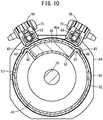
- detent grooves 48 are formed in the inner circumferential surface of the cylinder tube 82 to restrict rotation of the magnet holding portion 58 holding the magnet 46 relative to the cylinder tube 82.
- portions of the detent grooves 48 protrude to the side of the outer circumferential surface of the cylinder tube 82 to constitute rail-like protrusions 49.
- the detent grooves 48 and the rail-like protrusions 49 protrude radially outward and extend in the axial direction.
- the detent protrusions 60 provided for the holding member 44 of the piston unit 18 are engaged with the detent grooves 48, thereby restricting rotation of the holding member 44 relative to the cylinder tube 82. That is, the detent grooves 48 and the detent protrusions 60 constitute the rotation restriction structure.
- a pair of the detent grooves 48 are formed on the circumferential both sides of the magnet holding portion 58 of the holding member 44.
- the rail-like protrusions 49 corresponding to the detent grooves 48 constitute an indicator portion indicating the position of the magnet 46. That is, it is indicated that the part between the pair of rail-like protrusions 49 opposes the outer end 46a of the magnet 46.
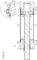
- screw holes 92 are provided adjacent to one end and another end of the cylinder tube 82.
- set screws 94 are screwed into the screw holes 92, and one end of each of the set screws 94 is in contact with the corresponding annular protruding portion 84c or 86c.
- the set screws 94 restrict circumferential rotation of the cylinder tube 82 relative to the rod cover 84 and the head cover 86. That is, the set screws 94 position the cylinder tube 82 in the circumferential direction.
- the set screws 94 constitute a positioning portion enabling the circumferential position of the cylinder tube 12 to be fixed with respect to the rod cover 84 and the head cover 86 (first and second covers).
- the magnetic sensors 64 are installed on the outer circumferential surface of the cylinder tube 82 via band-type sensor fixtures 68 (sensor fixing members).
- the sensor fixtures 68 each include a sensor holder 70 holding the corresponding magnetic sensor 64 and a band portion 69 securing the sensor holder 70 to the outer circumferential surface of the cylinder tube 82.
- the sensor holders 70 are secured to the cylinder tube 82 while being disposed between the pair of rail-like protrusions 49.
- the magnetic sensors 64 are disposed to oppose the outer end 46a of the magnet 46.
- the fluid pressure cylinder 80 according to the second embodiment also produces effects similar to the effects of the fluid pressure cylinder 10 according to the first embodiment. That is, the cylinder tube 82 can be rotated by loosening the set screws 94 of the cylinder tube 82.
- the installation positions of the magnetic sensors 64 can be changed flexibly depending on the layout of surrounding parts even after the fluid pressure cylinder 80 is installed in an instrument to be used. Since the position of the magnet 46 is indicated by the rail-like protrusions 49 protruding to the side of the outer circumference of the cylinder tube 82, the magnetic sensors 64 can be installed in appropriate positions. Moreover, since rotation of the holding member 44 relative to the cylinder tube 82 is restricted, an appropriate distance can be kept between the magnet 46 and the magnetic sensors 64 even when the piston rod 90 is rotated.
Landscapes
- Engineering & Computer Science (AREA)
- Physics & Mathematics (AREA)
- Fluid Mechanics (AREA)
- Mechanical Engineering (AREA)
- General Engineering & Computer Science (AREA)
- Actuator (AREA)
Abstract
Description
- The present invention relates to a fluid pressure cylinder (hydrostatic pressure cylinder) including a piston on which a magnet is disposed.
- For example, fluid pressure cylinders including pistons displaced according to supply of pressurized fluid have been known as units for carrying workpieces and the like (actuators). A typical fluid pressure cylinder includes a cylinder tube, a piston disposed inside the cylinder tube to be movable in the axial direction, and a piston rod connected to the piston.
- In a fluid pressure cylinder disclosed in Japanese Laid-Open Patent Publication No.
2008-133920 - Since magnets contain scarce resources, it is preferable that the magnets be reduced in size in view of saving resources.
- The fluid pressure cylinder is installed inside various instruments including carrying units before use, and the magnetic sensor installed outside the cylinder may become an obstacle depending on the layout of surrounding parts. Thus, there is a need for flexibility in changing the position of the magnetic sensor installed around the fluid pressure cylinder.
- However, in a case where a magnet is provided at one point in the circumferential direction, the installation position of the magnetic sensor is unfavorably limited by the position of the magnet since the magnetic sensor needs to be disposed close to the magnet.
- Therefore, the present invention has the object of providing a fluid pressure cylinder allowing the installation position of a magnetic sensor to be changed flexibly even with a magnet reduced in size.
- To achieve the above-described object, a fluid pressure cylinder according to the present invention comprises a cylinder tube including a slide hole with a circular shape inside the cylinder tube, a piston unit disposed to be reciprocable along the slide hole, a piston rod protruding from the piston unit in an axial direction, a magnet having a size corresponding to part of the piston unit in a circumferential direction, a holding member that includes a magnet holding portion configured to hold the magnet and that is attached to the piston unit, a rotation restriction structure configured to restrict rotation of the holding member relative to the cylinder tube, a first cover attached adjacent to one end of the cylinder tube, and a second cover attached adjacent to another end of the cylinder tube, wherein the cylinder tube is rotatable in the circumferential direction relative to the first and second covers, and the cylinder tube is provided with a positioning portion enabling a circumferential position of the cylinder tube to be fixed with respect to the first and second covers.
- In the above-described fluid pressure cylinder, the holding member holding the magnet is assembled to co-rotate with the cylinder tube by the rotation restriction structure, and the cylinder tube is installed to be rotatable relative to the first and second covers. Consequently, when the first and second covers are assembled to an instrument to be used, the orientation of the cylinder tube can be rotated so that a magnetic sensor can be disposed in a desired position. As a result, installation of the fluid pressure cylinder is simplified.
- In the above-described fluid pressure cylinder, the positioning portion may include a protrusion or a groove provided in an outer circumferential part of the cylinder tube, and a sensor fixing member configured to hold a magnetic sensor may be engaged with the protrusion or the groove to fix the circumferential position of the cylinder tube with respect to the first and second covers. In this manner, the circumferential position of the cylinder tube can be fixed by engaging the sensor fixing member with the protrusion or the groove provided in the outer circumferential part of the cylinder tube, resulting in a simplified adjustment of the sensor installation position in the fluid pressure cylinder.
- In the above-described fluid pressure cylinder, an indicator portion configured to indicate a position of the magnet may be formed in the outer circumferential part of the cylinder tube. In this case, the positioning portion may function as the indicator portion. Since the position of the magnet is indicated by the indicator portion, the magnetic sensor can be installed in an appropriate position in the outer circumferential part of the cylinder tube. In this case, the positioning portion may be configured as a rail-like protrusion extending in the axial direction in the outer circumferential part of the cylinder tube.
- In the above-described fluid pressure cylinder, the sensor fixing member may include a base end portion fixed relative to the first and second covers, and a sensor holding portion disposed adjacent to the positioning portion, and the sensor holding portion may be engaged with the positioning portion to position the cylinder tube in the circumferential direction. Since the sensor fixing member also functions as the positioning portion in this manner, the structure of the device is simplified.
- The above-described fluid pressure cylinder may further comprises a connecting rod passing through the first and second covers, a first securing mechanism configured to fix an axial position of the first cover with respect to the connecting rod, and a second securing mechanism configured to fix an axial position of the second cover with respect to the connecting rod, wherein the first and second securing mechanisms may secure the first and second covers to the cylinder tube without applying any axial load to the cylinder tube. As a result of this, the cylinder tube can be fixed to be rotatable relative to the first and second covers.
- In the above-described fluid pressure cylinder, the first securing mechanism may include a pair of first nuts screwed onto the connecting rod and configured to hold the first cover between the pair of first nuts in the axial direction, and the second securing mechanism may include a pair of second nuts screwed onto the connecting rod and configured to hold the second cover between the pair of second nuts in the axial direction. The first securing mechanism and the second securing mechanism can be achieved using a simple structure with nuts, and thus the structure can be simplified.
- In the above-described fluid pressure cylinder, the positioning portion may include set screws that pass through the cylinder tube in radial directions and that are in contact with the first and second covers. This enables the cylinder tube to be positioned in the circumferential direction.
- In the above-described fluid pressure cylinder, the cylinder tube may include a first narrowed portion engaged with the first cover, and a second narrowed portion engaged with the second cover, and the cylinder tube may be fixed to be rotatable relative to the first and second covers by the first and second narrowed portions. Thus, the cylinder tube can be fixed to be rotatable relative to the first and second covers.
- In the above-described fluid pressure cylinder, the holding member holding the magnet may be configured as a wear ring preventing the piston unit from coming into contact with the cylinder tube. Since the holding member is incorporated in the wear ring, the structure of the device is simplified, and the piston unit can be reduced in size and weight.
- In the above-described fluid pressure cylinder, the rotation restriction structure may include a detent groove formed in the slide hole and extending in the axial direction, and a detent protrusion formed in an outer circumferential part of the holding member and engaged with the detent groove. As a result, a configuration causing the holding member to rotate together with the cylinder tube can be achieved using a simple structure. Moreover, since the cylinder tube and the magnet co-rotate, the installation position of the magnetic sensor can be changed flexibly by rotating the cylinder tube.
- In accordance with the fluid pressure cylinder according to the present invention, the installation position of the magnetic sensor can be changed flexibly even with the magnet reduced in size.
-
-
FIG. 1 is a perspective view of a fluid pressure cylinder according to a first embodiment of the present invention; -
FIG. 2 is a longitudinal sectional view of the fluid pressure cylinder inFIG. 1 ; -
FIG. 3 is an exploded perspective view of the fluid pressure cylinder inFIG. 1 ; -
FIG. 4 is a cross-sectional view taken along line IV-IV inFIG. 2 ; -
FIGS. 5A, 5B, 5C, and 5D are perspective views respectively illustrating a first installation example, a second installation example, a third installation example, and a fourth installation example of a magnetic sensor of the fluid pressure cylinder inFIG. 1 ; -
FIG. 6 is a perspective view of a fluid pressure cylinder according to modification of the first embodiment; -
FIG. 7A is a cross-sectional view illustrating a first modification of the fluid pressure cylinder inFIG. 1 ,FIG. 7B is a cross-sectional view illustrating a second modification, andFIG. 7C is a cross-sectional view illustrating a third modification; -
FIG. 8 is a perspective view of a fluid pressure cylinder according to a second embodiment; -
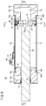
FIG. 9 is a longitudinal sectional view of the fluid pressure cylinder taken along line IX-IX inFIG. 8 ; -
FIG. 10 is a cross-sectional view taken along line X-X inFIG. 9 ; -
FIG. 11 is a longitudinal sectional view of the fluid pressure cylinder taken along line XI-XI inFIG. 9 ; and -
FIG. 12 is an exploded perspective view of the fluid pressure cylinder inFIG. 8 . - Preferred embodiments of a fluid pressure cylinder according to the present invention will be described in detail below with reference to the accompanying drawings.
- A
fluid pressure cylinder 10 according to a first embodiment illustrated inFIG. 1 includes a hollowtubular cylinder tube 12 having a circular slide hole 13 (cylinder chamber) inside thecylinder tube 12, a rod cover 14 (first cover) disposed at one end part of thecylinder tube 12, and a head cover 16 (second cover) disposed at another end part of thecylinder tube 12. As illustrated inFIGS. 2 and3 , thefluid pressure cylinder 10 further includes apiston unit 18 disposed inside thecylinder tube 12 to be movable in the axial direction (X direction), and apiston rod 20 connected to thepiston unit 18. Thefluid pressure cylinder 10 is used as an actuator for, for example, carrying a workpiece. - The
cylinder tube 12 is a tubular body made of, for example, a metal material such as aluminum alloy and extends in the axial direction. Thecylinder tube 12 has a hollow cylindrical shape. - As illustrated in
FIG. 3 , adetent groove 24 extends in the inner circumferential surface of thecylinder tube 12 in the axial direction of thecylinder tube 12. As illustrated inFIG. 4 , thedetent groove 24 is tapered (into a trapezoidal shape or a triangular shape) such that the width (circumferential width) thereof decreases radially outward. Thedetent groove 24 may have other polygonal shapes (for example, quadrangular shape). In the example illustrated in the drawings, thedetent groove 24 is formed in the inner circumferential surface of thecylinder tube 12 at one point in the circumferential direction. Note that a plurality of (for example, two)detent grooves 24 may be formed in the inner circumferential surface of thecylinder tube 12 at a distance from each other in the circumferential direction. - As illustrated in
FIGS. 1 and2 , therod cover 14 is a member made of, for example, a metal material similar to the material of thecylinder tube 12 and is provided to block up the one end part (an end part facing a direction of an arrow X1) of thecylinder tube 12. Therod cover 14 has afirst port 15a. As illustrated inFIG. 2 , an annular protrudingportion 14b provided for therod cover 14 is fitted in the one end part of thecylinder tube 12. - A packing 23 with a circular ring shape is disposed between the
rod cover 14 and thecylinder tube 12. A packing 27 with a circular ring shape and abush 25 with a circular ring shape are disposed in an inner circumferential part of therod cover 14. - The
head cover 16 is a member made of, for example, a metal material similar to the material of thecylinder tube 12 and is provided to block up the other end part (an end part facing a direction of an arrow X2) of thecylinder tube 12. Thehead cover 16 has asecond port 15b. An annular protrudingportion 16b provided for thehead cover 16 is fitted in the other end part of thecylinder tube 12. A packing 31 with a circular ring shape is disposed between thehead cover 16 and thecylinder tube 12. - As illustrated in
FIG. 1 , thecylinder tube 12, therod cover 14, and thehead cover 16 are connected to each other in the axial direction by a plurality of connectingrods 32 andnuts rods 32 are disposed at intervals in the circumferential direction. The connectingrods 32 pass through therod cover 14 andhead cover 16. Therod cover 14 is fastened while being held between the nuts 34 (first nuts) from both sides in the axial direction. This secures therod cover 14 in the axial direction of the connectingrods 32. Moreover, thehead cover 16 is fastened while being held between the nuts 36 (second nuts) from both sides in the axial direction. This secures thehead cover 16 in the axial direction of the connectingrods 32. - That is, the nuts 34 constitute a first securing mechanism securing the
rod cover 14 in the axial direction, and the nuts 36 constitute a second securing mechanism securing thehead cover 16 in the axial direction. Thus, thecylinder tube 12 is secured while not being pressed against therod cover 14 and thehead cover 16 in the axial direction. As a result, thecylinder tube 12 is rotatable relative to therod cover 14 and thehead cover 16. - As illustrated in
FIG. 2 , thepiston unit 18 is accommodated inside the cylinder tube 12 (slide hole 13) to be slidable in the axial direction and partitions the inside of theslide hole 13 into afirst pressure chamber 13a on thefirst port 15a side and asecond pressure chamber 13b on thesecond port 15b side. In this embodiment, thepiston unit 18 is connected to abase end portion 20a of thepiston rod 20. - As illustrated in
FIG. 3 , thepiston unit 18 includes acircular piston body 40 protruding radially outward from thepiston rod 20, a packing 42 with a circular ring shape attached to an outer circumferential part of thepiston body 40, amagnet 46 disposed partially in the circumferential direction of thepiston body 40, and a holdingmember 44 holding themagnet 46. - As illustrated in
FIG. 2 , thepiston body 40 has a through-hole 40a passing therethrough in the axial direction. Thebase end portion 20a of thepiston rod 20 is fitted in the through-hole 40a of thepiston body 40 and secured to thepiston body 40 by swaging. Thepiston rod 20 and thepiston body 40 may be secured to each other by screwing instead of swaging. Thepiston body 40 and thepiston rod 20 are preferably secured to each other to be rotatable in the circumferential direction. - A
packing receiving groove 50 and amagnet arrangement groove 52 are formed in the outer circumferential part of thepiston body 40 in different axial positions. Thepacking receiving groove 50 and themagnet arrangement groove 52 each have a circular ring shape extending around the entire circumference in the circumferential direction. Moreover, part of an outer circumferential part of themagnet arrangement groove 52 serves as a wearring supporting surface 54 extending in the axial direction. - The constituent material of the
piston body 40 includes, for example, metal materials such as carbon steel, stainless steel, and aluminum alloy and hard resin. - The packing 42 is a ring-shaped seal member made of an elastic material such as rubber or elastomer, and an O-ring, for example, can be used. The packing 42 is fitted in the
packing receiving groove 50. - The packing 42 is in contact with the inner circumferential surface of the
cylinder tube 12 to be slidable. Specifically, the packing 42 is disposed in a space between thepacking receiving groove 50 and thecylinder tube 12 while being elastically compressed, and an outer circumferential part of the packing 42 airtightly or fluid-tightly adheres to the inner circumferential surface of theslide hole 13 around the entire circumference. Moreover, the inner circumferential surface of the packing 42 airtightly or fluid-tightly adheres to the outer circumferential surface of thepiston body 40 in thepacking receiving groove 50. The packing 42 seals a gap between the outer circumferential surface of thepiston unit 18 and the inner circumferential surface of theslide hole 13 to airtightly or fluid-tightly separate thefirst pressure chamber 13a and thesecond pressure chamber 13b from each other inside theslide hole 13. - As illustrated in
FIG. 3 , thedetent groove 24 is formed in the inner circumferential surface of thecylinder tube 12. Thedetent groove 24 is filled up with part of the packing 42 expanding as the elastic compression is released at thedetent groove 24. Thus, the packing 42 airtightly or fluid-tightly adheres to thedetent groove 24. When thecylinder tube 12 rotates in the circumferential direction, the packing 42 rotates together with thecylinder tube 12 or other part of the packing 42 expands and deforms depending on how the packing 42 is attached. In either case, the packing 42 is kept airtightly or fluid-tightly adhering to thedetent groove 24. - In a case where a plurality of
detent grooves 24 are formed in the inner circumferential surface of thecylinder tube 12 at intervals in the circumferential direction, the packing 42 expands and deforms to fill up thedetent grooves 24 at a plurality of points at intervals in the circumferential direction. - The holding
member 44 is attached to thepiston body 40 to be rotatable. As a result, the holdingmember 44 is rotatable relative to thepiston rod 20. The holdingmember 44 includes acircumferential portion 57 extending in the circumferential direction along the outer circumferential part of thepiston body 40, and amagnet holding portion 58 protruding inward from thecircumferential portion 57. Themagnet holding portion 58 is disposed at one point in the circumferential direction. A plurality ofmagnet holding portions 58 may be disposed at intervals in the circumferential direction. - The
magnet holding portion 58 is fitted in themagnet arrangement groove 52 of thepiston body 40. Themagnet holding portion 58 has a through-hole part 58a passing through in the axial direction of the holdingmember 44. Themagnet 46 is fitted and held in the through-hole part 58a. - The
magnet holding portion 58 protrudes radially inward from an innercircumferential surface 57c of thecircumferential portion 57. More specifically, themagnet holding portion 58 is formed of aU-shaped frame part 58b protruding radially inward from thecircumferential portion 57 and the through-hole part 58a, which is the inside of theframe part 58b. Thus, both ends of themagnet holding portion 58 in the axial direction are open, allowing themagnet 46 to be inserted in either direction. - The axial dimension of the
magnet holding portion 58 may be smaller than the axial dimension of thecircumferential portion 57. In this case, themagnet holding portion 58 is disposed within the axial dimension of thecircumferential portion 57. - In this embodiment, the holding
member 44 is awear ring 44A configured to prevent thepiston body 40 from coming into contact with thecylinder tube 12, and is attached to the wearring supporting surface 54. Thewear ring 44A prevents the outer circumferential surface of thepiston body 40 from coming into contact with the inner circumferential surface of theslide hole 13 when a large lateral load is applied to thepiston unit 18 in a direction perpendicular to the axial direction while thefluid pressure cylinder 10 is in operation. The outer diameter of thewear ring 44A is greater than the outer diameter of thepiston body 40. - The
wear ring 44A is made of a low friction material. The friction coefficient between thewear ring 44A and the inner circumferential surface of theslide hole 13 is smaller than the friction coefficient between the packing 42 and the inner circumferential surface of theslide hole 13. Such a low friction material includes, for example, synthetic resins with a low coefficient of friction and a high resistance to wear such as polytetrafluoroethylene (PTFE), and metal materials including, for example, bearing steel. - The
circumferential portion 57 is attached to the wearring supporting surface 54 of thepiston body 40. Thecircumferential portion 57 has a circular ring shape with aslit 57a (seeFIG. 3 ) formed at a point in the circumferential direction. Theslit 57a is formed in a position offset from themagnet holding portion 58 in the circumferential direction. During assembly, the holdingmember 44 is forcibly expanded in radial directions and is disposed around the wearring supporting surface 54. The holdingmember 44 is then attached to themagnet arrangement groove 52 and the wearring supporting surface 54 as the diameter of the holdingmember 44 decreases by the elastic restoring force. - Rotation of the holding
member 44 relative to thecylinder tube 12 is restricted. That is, thedetent groove 24 is formed in the inner circumferential surface of thecylinder tube 12 in the axial direction of thecylinder tube 12, and adetent protrusion 60 engaged with thedetent groove 24 is provided for the holdingmember 44. Thedetent groove 24 and thedetent protrusion 60 constitute a rotation restriction structure. Thedetent protrusion 60 is slidable in thedetent groove 24 in the axial direction. - The
detent protrusion 60 protrudes radially outward from an outer circumferential part of the holdingmember 44. Thedetent protrusion 60 is disposed on an outercircumferential surface 57b of thecircumferential portion 57 in a position overlapping with themagnet holding portion 58 in the circumferential direction. Thedetent protrusion 60 extends on thecircumferential portion 57 over the entire axial length of thecircumferential portion 57. Thedetent protrusion 60 may be disposed in a position offset from themagnet holding portion 58 in the circumferential direction. - The
detent protrusion 60 has a shape similar to the shape of thedetent groove 24. Moreover, in the case where the plurality ofdetent grooves 24 are formed in the inner circumferential surface of thecylinder tube 12 at intervals in the circumferential direction, a plurality ofdetent protrusions 60 may be disposed on the holdingmember 44 at intervals in the circumferential direction. In this case, the number ofdetent protrusions 60 may be the same as or less than the number ofdetent grooves 24. - The
magnet 46 has a non-ring shape, exists in thepiston body 40 only at a point in the circumferential direction, and is fitted in themagnet holding portion 58. Although onemagnet 46 is fitted in onemagnet holding portion 58 in this embodiment, a configuration may be adopted in which a plurality ofmagnets 46 are used. Anouter end 46a of themagnet 46 fitted in themagnet holding portion 58 opposes the inner circumferential surface of thecylinder tube 12. Themagnet 46 is, for example, a ferrite magnet or a rare earth magnet. - As illustrated in
FIG. 2 , amagnetic sensor 64 is installed outside thecylinder tube 12. Specifically, a sensor bracket 66 (sensor fixing member) is attached to one of the connectingrods 32 illustrated inFIG. 1 . Themagnetic sensor 64 is held by thesensor bracket 66. Thus, the position of themagnetic sensor 64 is fixed with respect to thehead cover 16 and therod cover 14 via thesensor bracket 66 and the connectingrod 32. Themagnetic sensor 64 detects magnetism generated by themagnets 46 to detect the working position of thepiston unit 18. - As illustrated in
FIG. 3 , thesensor bracket 66 includes ahook portion 66a with a curvature equal to the curvature of the outer circumferential surface of the connectingrod 32. Thehook portion 66a is fitted onto the connectingrod 32 so that thesensor bracket 66 is secured to the connectingrod 32. Moreover, anarm portion 66b extends from thehook portion 66a, and asensor holding portion 66c is disposed at an end of thearm portion 66b to hold themagnetic sensor 64. Thesensor holding portion 66c includes acontact part 66d that is brought into contact with the outer circumferential surface of thecylinder tube 12. - The
sensor bracket 66 of this embodiment is disposed close to rail-like protrusions 47 on an outer circumferential part of thecylinder tube 12. Specifically, the rail-like protrusions 47 are disposed on the outer circumferential part of thecylinder tube 12, in a part adjacent to themagnet holding portion 58 in the circumferential direction. The part between the pair of rail-like protrusions 47 opposes theouter end 46a of themagnet 46. Thecontact part 66d of thesensor bracket 66 is fitted between the two rail-like protrusions 47 (groove). The two rail-like protrusions 47 (or the groove therebetween) constitute a positioning portion enabling the circumferential position of thecylinder tube 12 to be fixed with respect to therod cover 14 and the head cover 16 (first and second covers). In this embodiment, the rail-like protrusions 47 constitute an indicator portion indicating the position of themagnet 46. Moreover, thesensor bracket 66 engaged with the rail-like protrusions 47 functions as the positioning portion that sets the circumferential position of thecylinder tube 12. - The rail-
like protrusions 47 are protrusions protruding radially outward from thecylinder tube 12 into shapes of rails and extend in the axial direction. The pair of rail-like protrusions 47 are disposed at a predetermined distance from each other in the circumferential direction. In a case where the circumferential distance (angular range) between the pair of rail-like protrusions 47 is larger than the angular range occupied by the circumferential dimension of themagnet 46, the rail-like protrusions 47 are disposed such that the middle of the gap between the pair of rail-like protrusions 47 coincides with the middle part of themagnet 46. - In a case where the angular range occupied by the
magnet 46 in the circumferential direction is larger than the angular range of the pair of rail-like protrusions 47 in the circumferential direction, the pair of rail-like protrusions 47 may be disposed in any positions within a range overlapping with themagnet 46. In this case, a plurality of pairs of rail-like protrusions 47 may be disposed. The indicator portion indicating the position of themagnet 46 is not limited to the rail-like protrusions 47 and may be formed of, for example, lines or grooves. - The
piston rod 20 is a columnar (circular cylindrical) member extending in the axial direction of theslide hole 13. Thepiston rod 20 passes through therod cover 14. Aworkpiece fixing portion 20b of thepiston rod 20 is exposed to the outside of theslide hole 13. - To use the
fluid pressure cylinder 10 described above, thefluid pressure cylinder 10 is installed in, for example, instruments such as units for carrying workpieces and the like (actuators), and then themagnetic sensor 64 is installed on thecylinder tube 12 in an appropriate position depending on the layout of surrounding parts. - Since the
cylinder tube 12 of thefluid pressure cylinder 10 is secured to therod cover 14 and thehead cover 16 while receiving no axial load, a user can rotate thecylinder tube 12 with hands. Thus, in a case where the rail-like protrusions 47 of thecylinder tube 12 are disposed adjacent to the first andsecond ports FIG. 5A , for example, a base end portion of thesensor bracket 66 is attached to the connectingrod 32 adjacent to the first andsecond ports contact part 66d of thesensor bracket 66 is then fitted between the two rail-like protrusions 47 to install themagnetic sensor 64 in an appropriate position. Moreover, by attaching thesensor bracket 66 and placing thesensor holding portion 66c between the two rail-like protrusions 47, rotation of thecylinder tube 12 in the circumferential direction is restricted, and positioning of thecylinder tube 12 in the circumferential direction is completed. - As illustrated in
FIG. 5B , the orientation of thesensor bracket 66 attached to the connectingrod 32 is changed depending on the circumferential position of the rail-like protrusions 47 so that thesensor bracket 66 can be engaged with the rail-like protrusions 47. Moreover, as illustrated inFIGS. 5C and 5D , thesensor bracket 66 can be attached to the other connectingrods 32. As illustrated inFIGS. 5A to 5D , the attachment position of thesensor bracket 66 can be changed flexibly only by rotating thecylinder tube 12 with bare hands. - The
fluid pressure cylinder 10 described above operates as follows. In the description below, air serving as pressurized fluid is used. However, gas other than air may be used. - In
FIG. 2 , in thefluid pressure cylinder 10, thepiston unit 18 is moved inside theslide hole 13 in the axial direction by the effect of air serving as the pressurized fluid introduced via thefirst port 15a or thesecond port 15b. This causes thepiston rod 20 connected to thepiston unit 18 to move back and forth. - Specifically, to displace (advance) the
piston unit 18 toward therod cover 14, pressurized fluid is supplied from a pressurized fluid supply source (not illustrated) to thesecond pressure chamber 13b via thesecond port 15b while thefirst port 15a is exposed to the atmosphere. This causes thepiston unit 18 to be pushed by the pressurized fluid toward therod cover 14. As a result, thepiston unit 18 is displaced (advanced) toward therod cover 14 together with thepiston rod 20. When thepiston unit 18 comes into contact with therod cover 14, the advancing motion of thepiston unit 18 stops. - On the other hand, to displace (return) the
piston body 40 toward thehead cover 16, pressurized fluid is supplied from the pressurized fluid supply source (not illustrated) to thefirst pressure chamber 13a via thefirst port 15a while thesecond port 15b is exposed to the atmosphere. This causes thepiston body 40 to be pushed by the pressurized fluid toward thehead cover 16. As a result, thepiston unit 18 is displaced toward thehead cover 16. When thepiston unit 18 comes into contact with thehead cover 16, the returning motion of thepiston unit 18 stops. - In this case, the
fluid pressure cylinder 10 according to the first embodiment produces the following effects. - According to the
fluid pressure cylinder 10, themagnet 46 is disposed only at the required point in the circumferential direction. This leads to resource savings on the material for the magnet. - Moreover, the holding
member 44 is provided with thedetent protrusion 60 configured to prevent the holdingmember 44 from rotating relative to thecylinder tube 12, thereby fixing the circumferential position of themagnet 46 with respect to thecylinder tube 12. Thus, displacement of themagnet 46 from themagnetic sensor 64 in the circumferential direction due to, for example, vibration during use can be prevented. - The positioning portion enabling the circumferential position of the
cylinder tube 12 to be fixed with respect to therod cover 14 and thehead cover 16 includes protrusions or a groove (the two rail-like protrusions 47 or the groove therebetween) provided in the outer circumferential part of thecylinder tube 12. The circumferential position of thecylinder tube 12 is fixed with respect to therod cover 14 and thehead cover 16 by engaging thesensor bracket 66 with the protrusions or the groove. This simple structure enables the circumferential position of thecylinder tube 12 to be fixed reliably. - Moreover, the
cylinder tube 12 is provided with the rail-like protrusions 47 indicating the position of themagnet 46. Themagnetic sensor 64 can be disposed in an appropriate position with respect to themagnet 46 by engaging thesensor bracket 66 holding themagnetic sensor 64 with the rail-like protrusions 47. - Moreover, since the
cylinder tube 12 is joined to therod cover 14 and thehead cover 16 without being pressurized in the axial direction, thecylinder tube 12 is rotatable relative to therod cover 14 and thehead cover 16. Thus, the installation position of themagnetic sensor 64 can be changed flexibly by rotating thecylinder tube 12 after thefluid pressure cylinder 10 is installed in an instrument to be used. The installation position of themagnetic sensor 64 can be changed without loosening the mounting nuts of the connectingrods 32. - Moreover, since rotation of the
cylinder tube 12 is restricted by engaging thesensor bracket 66 with the rail-like protrusions 47, thecylinder tube 12 can be positioned in the circumferential direction at the same time as installation of themagnetic sensor 64. Rotation of thecylinder tube 12 can be restricted without tightening the mounting nuts of the connectingrods 32. - The holding
member 44 is thewear ring 44A configured to prevent thepiston body 40 from coming into contact with thecylinder tube 12. Thus, the holdingmember 44 serves both as thewear ring 44A and a member holding themagnet 46, leading to simplification of the structure. - As illustrated in
FIG. 6 , thefluid pressure cylinder 10 described above may be provided with a plurality ofsensor brackets 66 holding themagnetic sensors 64. In the example illustrated in the drawing, themagnetic sensor 64 for detecting the position of thepiston unit 18 in the vicinity of therod cover 14 and themagnetic sensor 64 for detecting the position of thepiston unit 18 in the vicinity of thehead cover 16 are attached to the twosensor brackets 66. One of thesensor brackets 66 is attached to be engaged with the pair of rail-like protrusions 47. Theother sensor bracket 66 is attached to another connectingrod 32, and thesensor holding portion 66c of theother sensor bracket 66 is disposed close to the rail-like protrusions 47. - In a case where the plurality of
magnetic sensors 64 are disposed in different circumferential positions as described above, it is preferable that the circumferential size (angular range) of themagnet 46 be increased so that the installation positions of themagnetic sensors 64 overlap with themagnet 46 as illustrated inFIG. 7A . - Moreover, in a case where the circumferential size (angular range) of the
magnet 46 is set to 90° or more, thesensor brackets 66 can be disposed over two sides as illustrated inFIG. 7B , increasing flexibility in arranging thesensor brackets 66. In the case illustrated inFIG. 7B , a plurality of pairs of rail-like protrusions 47 may be disposed at a predetermined distance from each other in the circumferential direction. In addition, only one pair of rail-like protrusions 47 may be provided, and marks indicating the attachment positions ofother sensor brackets 66 may be provided on the outer circumferential surface of thecylinder tube 12. - Furthermore, in a case where the circumferential size (angular range) of the
magnet 46 is set to 180° or more, thesensor brackets 66 can be disposed over three sides, that is, the side with the ports and the both sides thereof, as illustrated inFIG. 7C , further increasing flexibility in arranging thesensor brackets 66. - A
fluid pressure cylinder 80 according to a second embodiment illustrated inFIG. 8 includes a hollowtubular cylinder tube 82 having thecircular slide hole 13 inside thecylinder tube 82, arod cover 84 disposed at one end part of thecylinder tube 82, and ahead cover 86 disposed at another end part of thecylinder tube 82. As illustrated inFIG. 9 , thefluid pressure cylinder 80 further includes thepiston unit 18 disposed inside thecylinder tube 82 to be movable in the axial direction (X direction), and apiston rod 90 connected to thepiston unit 18. - As illustrated in
FIG. 9 , therod cover 84 has thefirst port 15a. An annular protrudingportion 84c with a diameter substantially identical to the inner diameter of thecylinder tube 82 protrudes from therod cover 84. The packing 23 with a circular ring shape is attached to an outer circumferential part of the annular protrudingportion 84c to airtightly connect thecylinder tube 82 and therod cover 84. The packing 23 is in contact with thecylinder tube 82 to be slidable in the circumferential direction. - A
cylinder holding groove 84d is formed in a base end portion of the annular protrudingportion 84c. Thecylinder holding groove 84d has a circular ring shape extending around the entire circumferential area of the annular protrudingportion 84c. - The
head cover 86 has thesecond port 15b and includes an annular protrudingportion 86c. The annular protrudingportion 86c is a cylindrical portion with a diameter substantially identical to the inner diameter of thecylinder tube 82. The packing 31 with a circular ring shape is attached to an outer circumferential part of the annular protrudingportion 86c. Moreover, acylinder holding groove 86d is formed in a base end portion of the annular protrudingportion 86c. Thecylinder holding groove 86d has a circular ring shape extending around the entire circumferential area of the annular protrudingportion 86c. - The
cylinder tube 82 has a hollow cylindrical shape.Narrowed portions 82a (first and second narrowed portions) with a diameter smaller than the diameter of the other portion are provided at both ends of thecylinder tube 82. The narrowedportions 82a are engaged with thecylinder holding groove 84d of therod cover 84 and thecylinder holding groove 86d of thehead cover 86 to be slidable in the circumferential direction. Thus, thecylinder tube 82 is secured to therod cover 84 and thehead cover 86 in the axial direction. - As illustrated in
FIG. 10 ,detent grooves 48 are formed in the inner circumferential surface of thecylinder tube 82 to restrict rotation of themagnet holding portion 58 holding themagnet 46 relative to thecylinder tube 82. In this embodiment, portions of thedetent grooves 48 protrude to the side of the outer circumferential surface of thecylinder tube 82 to constitute rail-like protrusions 49. Thedetent grooves 48 and the rail-like protrusions 49 protrude radially outward and extend in the axial direction. The detent protrusions 60 provided for the holdingmember 44 of thepiston unit 18 are engaged with thedetent grooves 48, thereby restricting rotation of the holdingmember 44 relative to thecylinder tube 82. That is, thedetent grooves 48 and thedetent protrusions 60 constitute the rotation restriction structure. - A pair of the
detent grooves 48 are formed on the circumferential both sides of themagnet holding portion 58 of the holdingmember 44. The rail-like protrusions 49 corresponding to thedetent grooves 48 constitute an indicator portion indicating the position of themagnet 46. That is, it is indicated that the part between the pair of rail-like protrusions 49 opposes theouter end 46a of themagnet 46. - As illustrated in
FIG. 8 , screw holes 92 are provided adjacent to one end and another end of thecylinder tube 82. As illustrated inFIG. 11 , setscrews 94 are screwed into the screw holes 92, and one end of each of theset screws 94 is in contact with the corresponding annular protrudingportion cylinder tube 82 relative to therod cover 84 and thehead cover 86. That is, theset screws 94 position thecylinder tube 82 in the circumferential direction. Thus, theset screws 94 constitute a positioning portion enabling the circumferential position of thecylinder tube 12 to be fixed with respect to therod cover 84 and the head cover 86 (first and second covers). - As illustrated in
FIGS. 8 and12 , themagnetic sensors 64 are installed on the outer circumferential surface of thecylinder tube 82 via band-type sensor fixtures 68 (sensor fixing members). Thesensor fixtures 68 each include asensor holder 70 holding the correspondingmagnetic sensor 64 and aband portion 69 securing thesensor holder 70 to the outer circumferential surface of thecylinder tube 82. Thesensor holders 70 are secured to thecylinder tube 82 while being disposed between the pair of rail-like protrusions 49. Thus, as illustrated inFIG. 10 , themagnetic sensors 64 are disposed to oppose theouter end 46a of themagnet 46. - The
fluid pressure cylinder 80 according to the second embodiment also produces effects similar to the effects of thefluid pressure cylinder 10 according to the first embodiment. That is, thecylinder tube 82 can be rotated by loosening theset screws 94 of thecylinder tube 82. Thus, the installation positions of themagnetic sensors 64 can be changed flexibly depending on the layout of surrounding parts even after thefluid pressure cylinder 80 is installed in an instrument to be used. Since the position of themagnet 46 is indicated by the rail-like protrusions 49 protruding to the side of the outer circumference of thecylinder tube 82, themagnetic sensors 64 can be installed in appropriate positions. Moreover, since rotation of the holdingmember 44 relative to thecylinder tube 82 is restricted, an appropriate distance can be kept between themagnet 46 and themagnetic sensors 64 even when thepiston rod 90 is rotated.
Claims (12)
- A fluid pressure cylinder comprising:a cylinder tube including a slide hole with a circular shape inside the cylinder tube;a piston unit disposed to be reciprocable along the slide hole;a piston rod protruding from the piston unit in an axial direction;a magnet having a size corresponding to part of the piston unit in a circumferential direction;a holding member that includes a magnet holding portion configured to hold the magnet and that is attached to the piston unit;a rotation restriction structure configured to restrict rotation of the holding member relative to the cylinder tube;a first cover attached adjacent to one end of the cylinder tube; anda second cover attached adjacent to another end of the cylinder tube, wherein:the cylinder tube is rotatable in the circumferential direction relative to the first and second covers; andthe cylinder tube is provided with a positioning portion enabling a circumferential position of the cylinder tube to be fixed with respect to the first and second covers.
- The fluid pressure cylinder according to claim 1, wherein:the positioning portion includes a protrusion or a groove provided in an outer circumferential part of the cylinder tube; anda sensor fixing member configured to hold a magnetic sensor is engaged with the protrusion or the groove to fix the circumferential position of the cylinder tube with respect to the first and second covers.
- The fluid pressure cylinder according to claim 2, wherein an indicator portion configured to indicate a position of the magnet is formed in the outer circumferential part of the cylinder tube.
- The fluid pressure cylinder according to claim 3, wherein the positioning portion functions as the indicator portion.
- The fluid pressure cylinder according to any one of claims 2 to 4, wherein the positioning portion is formed of a rail-like protrusion extending in the axial direction in the outer circumferential part of the cylinder tube.
- The fluid pressure cylinder according to any one of claims 2 to 5, wherein the sensor fixing member includes a base end portion fixed relative to the first and second covers, and a sensor holding portion disposed adjacent to the positioning portion, and the sensor holding portion is engaged with the positioning portion to position the cylinder tube in the circumferential direction.
- The fluid pressure cylinder according to any one of claims 1 to 6, further comprising:a connecting rod passing through the first and second covers;a first securing mechanism configured to fix an axial position of the first cover with respect to the connecting rod; anda second securing mechanism configured to fix an axial position of the second cover with respect to the connecting rod, wherein:
the first and second securing mechanisms secure the first and second covers to the cylinder tube without applying any axial load to the cylinder tube. - The fluid pressure cylinder according to claim 7, wherein:the first securing mechanism includes a pair of first nuts screwed onto the connecting rod and configured to hold the first cover between the pair of first nuts in the axial direction; andthe second securing mechanism includes a pair of second nuts screwed onto the connecting rod and configured to hold the second cover between the pair of second nuts in the axial direction.
- The fluid pressure cylinder according to claim 1, wherein the positioning portion includes set screws that pass through the cylinder tube in radial directions and that are in contact with the first and second covers.
- The fluid pressure cylinder according to claim 9, wherein the cylinder tube includes a first narrowed portion engaged with the first cover, and a second narrowed portion engaged with the second cover, and the cylinder tube is fixed to be rotatable relative to the first and second covers by the first and second narrowed portions.
- The fluid pressure cylinder according to any one of claims 1 to 10, wherein the holding member includes a wear ring configured to prevent the piston unit from coming into contact with the cylinder tube.
- The fluid pressure cylinder according to any one of claims 1 to 11, wherein the rotation restriction structure includes a detent groove formed in the slide hole and extending in the axial direction, and a detent protrusion formed in an outer circumferential part of the holding member and engaged with the detent groove.
Applications Claiming Priority (2)
| Application Number | Priority Date | Filing Date | Title |
|---|---|---|---|
| JP2018011950A JP6718584B2 (en) | 2018-01-26 | 2018-01-26 | Fluid pressure cylinder |
| PCT/JP2018/041265 WO2019146213A1 (en) | 2018-01-26 | 2018-11-07 | Hydrostatic pressure cylinder |
Publications (2)
| Publication Number | Publication Date |
|---|---|
| EP3744986A1 true EP3744986A1 (en) | 2020-12-02 |
| EP3744986A4 EP3744986A4 (en) | 2021-11-10 |
Family
ID=67394554
Family Applications (1)
| Application Number | Title | Priority Date | Filing Date |
|---|---|---|---|
| EP18903004.2A Withdrawn EP3744986A4 (en) | 2018-01-26 | 2018-11-07 | Hydrostatic pressure cylinder |
Country Status (10)
| Country | Link |
|---|---|
| US (1) | US11168715B2 (en) |
| EP (1) | EP3744986A4 (en) |
| JP (1) | JP6718584B2 (en) |
| KR (1) | KR102317147B1 (en) |
| CN (1) | CN111656020A (en) |
| BR (1) | BR112020014981A2 (en) |
| MX (1) | MX2020007871A (en) |
| RU (1) | RU2020127954A (en) |
| TW (1) | TWI686543B (en) |
| WO (1) | WO2019146213A1 (en) |
Cited By (2)
| Publication number | Priority date | Publication date | Assignee | Title |
|---|---|---|---|---|
| KR20240094444A (en) * | 2022-12-16 | 2024-06-25 | 아시아나아이디티 주식회사 | Device for attaching sensor |
| EP4617530A1 (en) * | 2024-03-13 | 2025-09-17 | Kongsberg Automotive Holding 2 AS | Gear shift actuator |
Families Citing this family (2)
| Publication number | Priority date | Publication date | Assignee | Title |
|---|---|---|---|---|
| EP4497955A1 (en) * | 2023-07-27 | 2025-01-29 | ZF CV Systems Global GmbH | Pneumatic actuator with magnetic position sensor |
| EP4545807A1 (en) * | 2023-10-23 | 2025-04-30 | Goodrich Actuation Systems SAS | Actuator assembly |
Family Cites Families (20)
| Publication number | Priority date | Publication date | Assignee | Title |
|---|---|---|---|---|
| US3639868A (en) * | 1971-03-17 | 1972-02-01 | Bimba Mfg Co | Magnetic switch mounting means for a fluid motor unit |
| US4086456A (en) * | 1976-10-04 | 1978-04-25 | Cincinnati Milacron Inc. | Mounting for magnetic switch |
| DE3319522C2 (en) * | 1983-05-28 | 1985-08-29 | Festo-Maschinenfabrik Gottlieb Stoll, 7300 Esslingen | Pressure fluid operated piston-cylinder unit |
| CH674058A5 (en) * | 1986-10-22 | 1990-04-30 | Festo Kg | |
| FR2634256B1 (en) * | 1988-07-13 | 1992-12-31 | Automax | IMPROVED CYLINDER |
| US5011382A (en) * | 1989-01-26 | 1991-04-30 | Thompson George A | Reciprocating piston pump |
| DE19637296A1 (en) * | 1996-09-13 | 1998-03-19 | Wabco Gmbh | Piston / cylinder arrangement |
| AT405674B (en) * | 1997-04-08 | 1999-10-25 | Hygrama Ag | PNEUMATIC OR HYDRAULIC CYLINDER |
| JP3295619B2 (en) * | 1997-07-16 | 2002-06-24 | エスエムシー株式会社 | Sensor mounting for hydraulic cylinders |
| JP3796639B2 (en) * | 1997-09-19 | 2006-07-12 | Smc株式会社 | Fluid pressure cylinder |
| JP4467174B2 (en) * | 2000-12-06 | 2010-05-26 | 株式会社Taiyo | Position sensor mounting device |
| US7240607B2 (en) * | 2005-08-23 | 2007-07-10 | Polygon Company | Removable end plug |
| JP2008133920A (en) | 2006-11-29 | 2008-06-12 | Smc Corp | Fluid pressure cylinder |
| DE102007062909A1 (en) * | 2007-12-21 | 2009-06-25 | Sick Ag | sensor |
| JP5464408B2 (en) | 2009-05-18 | 2014-04-09 | Smc株式会社 | Fluid pressure cylinder |
| US10570934B2 (en) * | 2014-10-02 | 2020-02-25 | Smc Corporation | Fluidic cylinder |
| JP6292483B2 (en) | 2015-06-11 | 2018-03-14 | Smc株式会社 | Fluid pressure cylinder |
| JP6519865B2 (en) * | 2015-06-11 | 2019-05-29 | Smc株式会社 | Fluid pressure cylinder |
| US10001133B2 (en) | 2015-10-02 | 2018-06-19 | Sundyne, Llc | Low-cavitation impeller and pump |
| JP6808182B2 (en) * | 2017-09-07 | 2021-01-06 | Smc株式会社 | Fluid pressure cylinder |
-
2018
- 2018-01-26 JP JP2018011950A patent/JP6718584B2/en active Active
- 2018-11-07 BR BR112020014981-0A patent/BR112020014981A2/en not_active IP Right Cessation
- 2018-11-07 EP EP18903004.2A patent/EP3744986A4/en not_active Withdrawn
- 2018-11-07 RU RU2020127954A patent/RU2020127954A/en unknown
- 2018-11-07 WO PCT/JP2018/041265 patent/WO2019146213A1/en not_active Ceased
- 2018-11-07 CN CN201880087643.0A patent/CN111656020A/en active Pending
- 2018-11-07 MX MX2020007871A patent/MX2020007871A/en unknown
- 2018-11-07 US US16/964,815 patent/US11168715B2/en not_active Expired - Fee Related
- 2018-11-07 KR KR1020207023876A patent/KR102317147B1/en not_active Expired - Fee Related
- 2018-11-21 TW TW107141469A patent/TWI686543B/en not_active IP Right Cessation
Cited By (2)
| Publication number | Priority date | Publication date | Assignee | Title |
|---|---|---|---|---|
| KR20240094444A (en) * | 2022-12-16 | 2024-06-25 | 아시아나아이디티 주식회사 | Device for attaching sensor |
| EP4617530A1 (en) * | 2024-03-13 | 2025-09-17 | Kongsberg Automotive Holding 2 AS | Gear shift actuator |
Also Published As
| Publication number | Publication date |
|---|---|
| CN111656020A (en) | 2020-09-11 |
| TWI686543B (en) | 2020-03-01 |
| KR20200106967A (en) | 2020-09-15 |
| WO2019146213A1 (en) | 2019-08-01 |
| EP3744986A4 (en) | 2021-11-10 |
| US20210062834A1 (en) | 2021-03-04 |
| JP6718584B2 (en) | 2020-07-08 |
| US11168715B2 (en) | 2021-11-09 |
| JP2019128033A (en) | 2019-08-01 |
| MX2020007871A (en) | 2020-09-07 |
| TW201932720A (en) | 2019-08-16 |
| BR112020014981A2 (en) | 2020-12-22 |
| KR102317147B1 (en) | 2021-10-25 |
| RU2020127954A3 (en) | 2022-02-21 |
| RU2020127954A (en) | 2022-02-21 |
Similar Documents
| Publication | Publication Date | Title |
|---|---|---|
| US11168715B2 (en) | Hydrostatic pressure cylinder | |
| EP3680494B1 (en) | Hydraulic cylinder | |
| US11079017B2 (en) | Hydraulic cylinder | |
| EP3553327B1 (en) | Rod assembly and fluid pressure device | |
| JP2019044947A5 (en) | ||
| US11215204B2 (en) | Piston unit and hydraulic cylinder | |
| EP3770446A1 (en) | Fluid pressure cylinder | |
| JP6933985B2 (en) | Hydraulic equipment |
Legal Events
| Date | Code | Title | Description |
|---|---|---|---|
| STAA | Information on the status of an ep patent application or granted ep patent |
Free format text: STATUS: THE INTERNATIONAL PUBLICATION HAS BEEN MADE |
|
| PUAI | Public reference made under article 153(3) epc to a published international application that has entered the european phase |
Free format text: ORIGINAL CODE: 0009012 |
|
| STAA | Information on the status of an ep patent application or granted ep patent |
Free format text: STATUS: REQUEST FOR EXAMINATION WAS MADE |
|
| 17P | Request for examination filed |
Effective date: 20200814 |
|
| AK | Designated contracting states |
Kind code of ref document: A1 Designated state(s): AL AT BE BG CH CY CZ DE DK EE ES FI FR GB GR HR HU IE IS IT LI LT LU LV MC MK MT NL NO PL PT RO RS SE SI SK SM TR |
|
| AX | Request for extension of the european patent |
Extension state: BA ME |
|
| DAV | Request for validation of the european patent (deleted) | ||
| DAX | Request for extension of the european patent (deleted) | ||
| A4 | Supplementary search report drawn up and despatched |
Effective date: 20211008 |
|
| RIC1 | Information provided on ipc code assigned before grant |
Ipc: F15B 15/14 20060101ALI20211004BHEP Ipc: F15B 15/28 20060101AFI20211004BHEP |
|
| STAA | Information on the status of an ep patent application or granted ep patent |
Free format text: STATUS: THE APPLICATION HAS BEEN WITHDRAWN |
|
| 18W | Application withdrawn |
Effective date: 20220923 |