EP3744979B1 - Handluftpumpengriffanordnung und handluftpumpe - Google Patents
Handluftpumpengriffanordnung und handluftpumpe Download PDFInfo
- Publication number
- EP3744979B1 EP3744979B1 EP20174750.8A EP20174750A EP3744979B1 EP 3744979 B1 EP3744979 B1 EP 3744979B1 EP 20174750 A EP20174750 A EP 20174750A EP 3744979 B1 EP3744979 B1 EP 3744979B1
- Authority
- EP
- European Patent Office
- Prior art keywords
- air pump
- handle assembly
- pressure gauge
- hand air
- shock absorber
- Prior art date
- Legal status (The legal status is an assumption and is not a legal conclusion. Google has not performed a legal analysis and makes no representation as to the accuracy of the status listed.)
- Active
Links
Images



Classifications
-
- F—MECHANICAL ENGINEERING; LIGHTING; HEATING; WEAPONS; BLASTING
- F04—POSITIVE - DISPLACEMENT MACHINES FOR LIQUIDS; PUMPS FOR LIQUIDS OR ELASTIC FLUIDS
- F04B—POSITIVE-DISPLACEMENT MACHINES FOR LIQUIDS; PUMPS
- F04B33/00—Pumps actuated by muscle power, e.g. for inflating
-
- F—MECHANICAL ENGINEERING; LIGHTING; HEATING; WEAPONS; BLASTING
- F04—POSITIVE - DISPLACEMENT MACHINES FOR LIQUIDS; PUMPS FOR LIQUIDS OR ELASTIC FLUIDS
- F04B—POSITIVE-DISPLACEMENT MACHINES FOR LIQUIDS; PUMPS
- F04B33/00—Pumps actuated by muscle power, e.g. for inflating
- F04B33/005—Pumps actuated by muscle power, e.g. for inflating specially adapted for inflating tyres of non-motorised vehicles, e.g. cycles, tricycles
-
- F—MECHANICAL ENGINEERING; LIGHTING; HEATING; WEAPONS; BLASTING
- F04—POSITIVE - DISPLACEMENT MACHINES FOR LIQUIDS; PUMPS FOR LIQUIDS OR ELASTIC FLUIDS
- F04B—POSITIVE-DISPLACEMENT MACHINES FOR LIQUIDS; PUMPS
- F04B39/00—Component parts, details, or accessories, of pumps or pumping systems specially adapted for elastic fluids, not otherwise provided for in, or of interest apart from, groups F04B25/00 - F04B37/00
Definitions
- the present disclosure relates to a hand air pump handle assembly with an internal pressure gauge and a hand air pump including the hand air pump handle assembly.
- Inflatable bodies e.g., air mattresses, inflatable sofas, pneumatic tires and inflatable toys
- the amount of inflation as measured in units of pressure, generally needs to be relatively specific. Too much or too little inflation and the inflatable body can malfunction or break. Electric air pumps and hand air pumps are commonly used to inflate a large variety of inflatable bodies. Too help ensure that the inflatable body is inflated to an ideal pressure, pressure gauges (e.g., electronic and non-electronic pressure gauges) are sometimes mounted on air pump handles and provide current air pressure inside of the inflatable body as it is inflated.
- pressure gauges e.g., electronic and non-electronic pressure gauges
- While mounted pressure gauges have improved operability of certain air pumps, such mounted pressure gauges are generally directly and rigidly mounted onto the pump handle, and thus are susceptible to damage during misuse or an accident with the air pump. More particularly, pressure gauges mounted within air pump handles are not protected from potential damage from physical shock that may result from, for example, dropping the air pump. Generally, when a pressure gauge breaks, it is cheaper and/or more efficient to buy a new air pump rather than attempting to fix the old air pump by replacing the broken pressure gauge.
- US 8,721,296 B1 relates to o a hand pump or air pump for inflating the inflatable tires or objects or the like of the cycles, such as the bicycles, and more particularly to a hand pump or air pump for a bicycle including an air storage tank.
- GB 251 721 A discloses inflators for tyres or other inflatable bodies.
- a hand air pump handle assembly comprises a handle shell defining an accommodating space and having an air vent in fluid communication with both the accommodating space and a provided inflatable body.
- a pressure gauge is located and elastically supported within the accommodating space.
- a flexible connecting tube is in the accommodating space of the handle shell and comprises a first end and a second end and a tube joint connecting the flexible connecting tube to the air vent.
- a flexible shock absorber is provided being arranged between the pressure gauge and the handle shell for dampening impact between the handle shell and the pressure gauge.
- the hand air pump handle assembly includes an elastic connector connecting the pressure gauge to the handle shell to permit movement of the pressure gauge within the accommodating space.
- the pressure gauge comprises a pressure gauge body and a pressure probe extending from the pressure gauge body and in fluid communication with the provided inflatable body through the flexible connecting tube.
- the elastic connector comprises a resisting member at least partially sleeved over an outer side of the flexible connecting tube.
- the resisting member comprises a support portion for supporting the pressure gauge body and a raised portion protruding radially inward along the support portion to contact the flexible connecting tube.
- the elastic connector further comprises a spring sleeved over the outer side of the flexible connecting tube and extending between a pair of ends thereof, wherein one end of the spring abuts against the raised portion of the resisting member, and the other end of the spring is fixed in an annular recess located around the air vent.
- the flexible connecting tube extends between a pair of ends thereof, wherein one end of the flexible connecting tube is fixed between the raised portion of the resisting member and the pressure probe, and the other end of the flexible connecting tube forms an interference fit with the tube joint.
- the pressure probe includes a threaded portion extending through the raised portion of the resistance member, and the flexible connecting tube fits between the threaded portion and the raised portion.
- the hand air pump handle assembly further includes at least a pair of cable ties, wherein one of the pair of cable ties affixes the first end of the flexible connecting tube to the pressure probe and the other one of the pair of cable ties affixes the second end of the flexible connecting tube to the tube joint.
- the hand air pump handle assembly further includes a fixing member affixing the tube joint to the handle shell.
- the tube joint further includes a protrusion located in the accommodating space that extends a diameter of the tube joint such that the diameter is larger than a diameter of the air vent and a seal washer located between the protrusion and the handle shell.
- the tube joint is at least partially threaded, and the fixing member includes a nut engaged thereon.
- the hand air pump handle assembly further includes flexible shock absorber arranged between the pressure gauge and the handle shell for dampening impact between the handle shell and the pressure gauge.
- the flexible shock absorber comprises a shock absorber body at least partially covering the pressure gauge.
- the flexible shock absorber further comprises at least one shock absorber leg extending from the shock absorber body towards the handle shell to provide additional dampening.
- the hand air pump handle assembly further includes a holder for the flexible shock absorber fixed in the accommodating space for contacting the shock absorber leg and causing the shock absorber leg to move as the pressure gauge is moved.
- the flexible shock absorber may comprise a rubber member or a sponge-like material.
- the hand air pump handle assembly further includes the provided inflatable body, wherein the provided inflatable body comprises at least one of an inflatable sofa, an air mattress, an inflatable toy, or a pneumatic tire.
- the hand air pump handle assembly further includes a cover that can be connected to and disconnected from the handle shell.
- the cover is at least partially transparent so that the pressure gauge can be viewed therethrough.
- the hand air pump handle assembly further includes a pair of grip portions extending from opposite sides of the handle shell.
- the handle shell and the pair of grip portions may be integrally formed.
- FIG 1 to Figure 5 schematically illustrate a first embodiment of a hand air pump handle assembly 1 according to the present disclosure.
- the hand air pump handle assembly 1 mainly comprises a handle shell 11 mounted with a pressure gauge 2, two grip portions 12, a first connector 13, and a second connector 14.
- the handle shell 11 defines an internal accommodating space 111 for housing the pressure gauge 2.
- the handle shell 11 further defines an air vent 112 formed near the bottom of the accommodating space 111 to connect the accommodating space 111 to a pump body (not shown) of the hand air pump and a provided inflatable body (not shown and alternatively referred to as inflatable body).
- the inflatable body may comprise an air mattress, an inflatable sofa, a pneumatic tire, an inflatable toy, or any other item requiring inflation.
- the hand air pump handle assembly 1 further comprises a cover 8 fixed to the top of the handle shell 11 to close the accommodating space 111.
- the cover 8 may be fixedly connected to the handle shell 11 by fixing members, such as bolts 81.
- the cover 8 may include a transparent region through which a user can directly observe an air pressure value shown on the pressure gauge 2.
- the two grip portions 12 extend oppositely from sides of the handle shell 11 for the user to grab with each hand while inflating.
- the first connector 13 extends through a the bottom of the handle shell 11 to connect the pump body of the hand air pump to the accommodating space 111 via the air vent 112.
- the second connector 14 is located between the handle shell 11 and the first connector 13 to connect the inflatable body via an external inflation tube (not shown). More particularly, one end of the inflation tube is connected to the second connector 14 and the other end of the inflation tube is connected to the inflatable body. As such, the inflatable body can communicate with the pump body and the accommodating space 111 via the air vent 112.
- the handle shell 11, the two grip portions 12, the first connector 13 and the second connector 14 are preferably integrally formed.
- the pressure gauge 2 is located in the accommodating space 111 and connected to the handle shell 11 by an elastic connector 15 that comprises materials and/or components that allow the pressure gauge 2 to move elastically within the accommodating space 111.
- the pressure gauge 2 comprises a pressure gauge body 21 and a pressure probe 22.
- the pressure probe 22 may include a metal probe with an external thread.
- the pressure probe 22 extends from the pressure gauge body 21 toward the air vent 112 and communicates with the inflatable body via a flexible connecting tube 3 (e.g., a silicone connecting tube).
- the flexible connecting tube 3 is at least partially located in the accommodating space 111 of the handle shell 11 and extends from the pressure probe 22 to the vent 112 in order to communicate the internal air pressure value of the inflatable body to the pressure gauge 2.
- the elastic connector 15 includes a resisting member 4 and a spring 5 that enables the pressure gauge 2 to elastically travel a small dampened distance when under the impact of external forces.
- the resisting member 4 assists in the connection between the pressure gauge 2 and the flexible connecting tube 3. More particularly, the resisting member 4 is sleeved on an outer side of at least a portion of the flexible connecting tube 3.
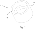
- the resisting member 4 is illustrated in Figure 5 and comprises a support portion 41 for supporting the pressure gauge body 21 and a raised portion 42 protruding radially inward along the support portion 41 to abut against the flexible connecting tube 3.
- the spring 5 is sleeved on the outer side of the flexible connecting tube 3 under the resisting member 4 opposite from the pressure gauge 2.
- the flexible connecting tube 3 extends between an upper end portion and a lower end portion.
- the upper end portion is fixed between the raised portion 42 and the pressure probe 22, and the lower end portion is fixed in communication with the air vent 112 through a tube joint 6.
- the tube joint 6 extends from the accommodating space 111 into the air vent 112.
- the upper end portion of the flexible connecting tube 3 is fixed by the abutment (such as by a pressure fit) between the raised portion 42 and the threaded pressure probe 22.
- the lower end portion of the flexible connecting tube 3 forms an interference fit with the tube joint 6, such that it is fixed in the accommodating space 111 of the handle shell 11 and is in communication with the air vent 112 and pressure gauge 2.
- the hand air pump handle assembly 1 may further include a flexible shock absorber 7 to further improve the impact resistance of the hand air pump handle assembly 1.
- the flexible shock absorber 7 may be arranged between the pressure gauge 2 and the handle shell 11 and may further at least partially cover the pressure gauge 2.
- the flexible shock absorber 7 may be arranged around the pressure gauge body 21 such that it is located between the pressure gauge body 21 and the handle shell 11 to prevent the pressure gauge 2 from directly impacting the handle shell 11 under the influence of external force.
- the flexible shock absorber 7 may comprise of a rubber or a sponge-like material.
- Figure 6 illustrates a second embodiment of a hand air pump handle assembly 1.
- the flexible connecting tube 3 in the second embodiment is fixed in place by at least one of a collar or a ribbon 31. More specifically, the upper end portion of the flexible connecting tube 3 is connected to the pressure probe 22 by a collar or a ribbon 31, and the lower end portion is connected to the upper end portion of the tube joint 6 by a collar or a ribbon 31.
- the tube joint 6 includes a lower end portion that is threaded and at least partially extends through the air vent 112 and is fixed to the handle shell 11 by a fixing member, such as a nut 63.
- the tube joint 6 may further comprise a protrusion 61 extending radially outward above the air vent 112 to assist in supporting the handle shell 11.
- the protrusion 61 is located in the accommodating space 111 and extends a diameter of the tube joint 6 such that the diameter is larger than a diameter of the air vent 112 and cannot be removed therethrough.
- a seal washer 62 surrounding the tube joint 6 is further arranged between the protrusion 61 and the air vent 112 to prevent gas from leaking between the handle shell 11 and the protrusion 61, thereby ensuring that the pressure value detected by the pressure gauge 2 is more accurate.
- the flexible shock absorber 7 may further comprise a shock absorber body 71 that at least partially covers the pressure gauge 2 and at least one shock absorber leg 72 extending from the shock absorber body 71 towards the handle shell 11.
- the shock absorber leg 72 may further bias the pressure gauge 2 away from the handle shell 11.
- the hand air pump handle assembly 1 may further include a shock absorber holder 73 fixed in the accommodating space 111 of the handle shell 11 to support the at least one shock absorber leg 72.
- the shock absorber body 71 covers the sides and a bottom of the pressure gauge body 21, and the shock absorber holder 73 is fixed in the accommodating space 111 by means of fixing members, such as bolts.
- the shock absorber holder 73 is thus located to support the at least one shock absorber leg 72 extending downward from the bottom of the shock absorber body 71.
- the at least one shock absorber leg 72 may include a plurality of shock absorber legs 72, for example, a pair of shock absorber legs 72.
Landscapes
- Engineering & Computer Science (AREA)
- Mechanical Engineering (AREA)
- General Engineering & Computer Science (AREA)
- Compressors, Vaccum Pumps And Other Relevant Systems (AREA)
Claims (14)
- Handluftpumpengriffanordnung (1), umfassend:einen Aufnahmeraum (111) und aufweisend eine Luftöffnung (112) in Fluidverbindung mit sowohl dem Aufnahmeraum (111) als auch einem bereitgestellten aufblasbaren Körper;ein Manometer (2), das in dem Aufnahmeraum (111) angeordnet und elastisch gelagert ist;einen flexiblen Verbindungsschlauch (3) in dem Aufnahmeraum (111) und umfassend ein erstes Ende und ein zweites Ende;einen Schlauchverbinder (6), der den flexiblen Verbindungsschlauch (3) mit der Luftöffnung (112) verbindet; unddadurch gekennzeichnet, dass die Handluftpumpengriffanordnung umfasst:eine Griffschale (11), die den Aufnahmeraum (111) definiert;einen flexiblen Stoßdämpfer (7), der zwischen dem Manometer (2) und der Griffschale (11) zur Stoßdämpfung zwischen der Griffschale (11) und dem Manometer (2) angeordnet ist.
- Handluftpumpengriffanordnung (1) nach Anspruch 1, ferner umfassend: einen elastischen Verbinder (15), der das Manometer (2) mit der Griffschale (11) verbindet, um eine Bewegung des Manometers (2) in dem Aufnahmeraum (111) zu gestatten;
wobei das Manometer (2) umfasst:einen Manometerkörper (21); undeine Drucksonde (22), die sich von dem Manometerkörper (21) erstreckt und mit dem bereitgestellten aufblasbaren Körper über den flexiblen Verbindungsschlauch (3) in Fluidverbindung steht. - Handluftpumpengriffanordnung (1) nach Anspruch 2, wobei der elastische Verbinder (15) umfasst:ein Widerstandselement (4), das zumindest teilweise über eine Außenseite des flexiblen Verbindungsschlauchs (3) geschoben ist, wobei das Widerstandselement (4) einen Stützabschnitt (41) zum Stützen des Manometerkörpers (21) und einen erhöhten Abschnitt (42) umfasst, der entlang des Stützabschnitts (42) radial nach innen vorsteht, um den flexiblen Verbindungsschlauch (3) zu kontaktieren; undeine Feder (5), die über die Außenseite des flexiblen Verbindungsschlauchs (3) geschoben ist und sich zwischen einem Paar von dessen Enden erstreckt, wobei ein Ende der Feder (5) an dem erhöhten Abschnitt (42) des Widerstandselements (4) anliegt und das andere Ende der Feder (5) in einer ringförmigen Vertiefung (113) befestigt ist, die sich um die Luftöffnung (112) befindet.
- Handluftpumpengriffanordnung (1) nach Anspruch 3, wobei sich der flexible Verbindungsschlauch (3) zwischen dem ersten Ende und dem zweiten Ende erstreckt, wobei das erste Ende des flexiblen Verbindungsschlauchs (3) zwischen dem erhöhten Abschnitt (42) des Widerstandselements (4) und der Drucksonde (22) befestigt ist und das zweite Ende des flexiblen Verbindungsschlauchs (3) eine Presspassung mit dem Schlauchverbinder (6) bildet.
- Handluftpumpengriffanordnung (1) nach Anspruch 4, wobei die Drucksonde (22) einen Gewindeabschnitt umfasst, der sich durch den erhöhten Abschnitt (42) des Widerstandselements (4) erstreckt, und wobei der flexible Verbindungsschlauch (3) zwischen den Gewindeabschnitt und den erhöhten Abschnitt (42) passt.
- Handluftpumpengriffanordnung (1) nach Anspruch 1, ferner umfassend mindestens ein Paar von Kabelbindern, wobei einer von dem Paar von Kabelbindern das erste Ende des flexiblen Verbindungsschlauchs (3) an der Drucksonde (22) befestigt und der andere von dem Paar von Kabelbindern das zweite Ende des flexiblen Verbindungsschlauchs (3) an dem Schlauchverbinder (6) befestigt.
- Handluftpumpengriffanordnung (1) nach Anspruch 6, ferner umfassend ein Befestigungselement (81), das den Schlauchverbinder (6) an der Griffschale (11) befestigt.
- Handluftpumpengriffanordnung (1) nach Anspruch 7, wobei der Schlauchverbinder (6) ferner umfasst:einen in dem Aufnahmeraum (111) befindlichen Vorsprung (61), der einen Durchmesser des Schlauchverbinders (6) derart vergrößert, dass der Durchmesser größer als ein Durchmesser der Luftöffnung (112) ist; undeinen Dichtungsring (62), der sich zwischen dem Vorsprung (61) und der Griffschale (11) befindet.
- Handluftpumpengriffanordnung (1) nach Anspruch 8, wobei der Schlauchverbinder (6) zumindest teilweise mit einem Gewinde versehen ist und das Befestigungselement (81) eine darauf in Eingriff befindliche Nut (63) umfasst.
- Handluftpumpengriffanordnung (1) nach Anspruch 1, wobei der flexible Stoßdämpfer (7) einen Stoßdämpferkörper (71) umfasst, der das Manometer (2) zumindest teilweise bedeckt.
- Handluftpumpengriffanordnung (1) nach Anspruch 10, wobei der flexible Stoßdämpfer (7) ferner mindestens ein Stoßdämpferbein (72) umfasst, das sich von dem Stoßdämpferkörper (71) zur Griffschale (11) erstreckt, um für zusätzliche Dämpfung zu sorgen.
- Handluftpumpengriffanordnung (1) nach Anspruch 11, ferner umfassend eine Halterung (73) für den flexiblen Stoßdämpfer (7), die in dem Aufnahmeraum (111) zum Kontaktieren des Stoßdämpferbeins (72) befestigt ist und bewirkt, dass sich das Stoßdämpferbein (72) bewegt, wenn das Manometer (2) bewegt wird.
- Handluftpumpengriffanordnung (1) nach Anspruch 1, wobei der flexible Stoßdämpfer (7) ein Gummielement umfasst.
- Handluftpumpengriffanordnung (1) nach Anspruch 1, ferner umfassend eine Abdeckung (8), die mit der Griffschale (11) verbunden und von ihr gelöst werden kann, wobei die Abdeckung (8) zumindest teilweise transparent ist, sodass das Manometer (2) durch sie hindurch sichtbar ist.
Applications Claiming Priority (1)
| Application Number | Priority Date | Filing Date | Title |
|---|---|---|---|
| CN201920767603.2U CN209875418U (zh) | 2019-05-27 | 2019-05-27 | 手动气泵手柄组件及手动气泵 |
Publications (2)
| Publication Number | Publication Date |
|---|---|
| EP3744979A1 EP3744979A1 (de) | 2020-12-02 |
| EP3744979B1 true EP3744979B1 (de) | 2023-07-05 |
Family
ID=68947932
Family Applications (1)
| Application Number | Title | Priority Date | Filing Date |
|---|---|---|---|
| EP20174750.8A Active EP3744979B1 (de) | 2019-05-27 | 2020-05-14 | Handluftpumpengriffanordnung und handluftpumpe |
Country Status (3)
| Country | Link |
|---|---|
| US (1) | US11454228B2 (de) |
| EP (1) | EP3744979B1 (de) |
| CN (1) | CN209875418U (de) |
Families Citing this family (1)
| Publication number | Priority date | Publication date | Assignee | Title |
|---|---|---|---|---|
| CN111441932B (zh) * | 2020-04-24 | 2025-08-26 | 宁波美高厨具有限公司 | 一种气泵组件及清洗机 |
Family Cites Families (7)
| Publication number | Priority date | Publication date | Assignee | Title |
|---|---|---|---|---|
| GB251721A (en) * | 1925-02-25 | 1926-05-13 | Millicent Smith | Improvements in inflators |
| US3888127A (en) * | 1972-11-10 | 1975-06-10 | Farallon Ind | Portable underwater indicating instrument for divers |
| US5335543A (en) * | 1993-03-16 | 1994-08-09 | U.S. Divers Co., Inc. | Diver's pivotal gauge boot |
| US6485264B1 (en) * | 2000-06-16 | 2002-11-26 | Scott Wu | Anti-leakage device for a manual air pump with a pressure gauge |
| US8721296B1 (en) * | 2013-01-28 | 2014-05-13 | Beto Engineering & Marketing Co., Ltd. | Hand pump with air storage tank |
| TWI540254B (zh) * | 2015-02-10 | 2016-07-01 | Shu-Mu Wu | Rotating the pressure gauge |
| TW201802355A (zh) * | 2016-07-06 | 2018-01-16 | 極點股份有限公司 | 打氣裝置 |
-
2019
- 2019-05-27 CN CN201920767603.2U patent/CN209875418U/zh active Active
-
2020
- 2020-05-14 EP EP20174750.8A patent/EP3744979B1/de active Active
- 2020-05-26 US US16/883,599 patent/US11454228B2/en active Active
Also Published As
| Publication number | Publication date |
|---|---|
| EP3744979A1 (de) | 2020-12-02 |
| US11454228B2 (en) | 2022-09-27 |
| CN209875418U (zh) | 2019-12-31 |
| US20200378376A1 (en) | 2020-12-03 |
Similar Documents
| Publication | Publication Date | Title |
|---|---|---|
| US6543277B2 (en) | Non-attached monitoring assembly for pneumatic tire | |
| US11454228B2 (en) | Hand air pump handle assembly and hand air pump | |
| CN110253602A (zh) | 一种内撑式夹具 | |
| WO2016109030A1 (en) | Tire electronics securing structures | |
| GB2528743A (en) | Bicycle including frame with inflatable segments | |
| US5816284A (en) | Tire valve extension attachment | |
| JP2006507185A (ja) | 空気入りタイヤ用非付着モニタリングアセンブリ | |
| US4653550A (en) | Portable refillable inflator | |
| US2391120A (en) | Spring means | |
| US8540595B1 (en) | Ball inflation valve | |
| US9488540B2 (en) | Barometer with multi-functions of measurement and depressurization | |
| CN214633702U (zh) | 站位动静态平衡功能训练、评估系统 | |
| KR20170053833A (ko) | 에어백 헬멧 | |
| JP2003182321A (ja) | タイヤ状態監視装置の送信機 | |
| US20150021873A1 (en) | Wheel system for a vehicle | |
| US20090114294A1 (en) | Portable gas shock or air bag inflator or deflator | |
| US20030144096A1 (en) | Inflatable device | |
| CA1333252C (en) | Pressure indicating valve stem | |
| CN211314475U (zh) | 一种脚踏充气筒 | |
| CN205632431U (zh) | 新型轮胎充气装置 | |
| US3117195A (en) | Pmneumatic tire and electric switch for pressure indicator | |
| CN222254862U (zh) | 一种新型空簧皮囊保护罩 | |
| CN107035656A (zh) | 一种可移动的充气橡胶制品装置 | |
| CN219639012U (zh) | 可旋转充气接头及充气泵 | |
| CN212320986U (zh) | 一种便于检测轮胎气压的车载装置 |
Legal Events
| Date | Code | Title | Description |
|---|---|---|---|
| PUAI | Public reference made under article 153(3) epc to a published international application that has entered the european phase |
Free format text: ORIGINAL CODE: 0009012 |
|
| STAA | Information on the status of an ep patent application or granted ep patent |
Free format text: STATUS: THE APPLICATION HAS BEEN PUBLISHED |
|
| AK | Designated contracting states |
Kind code of ref document: A1 Designated state(s): AL AT BE BG CH CY CZ DE DK EE ES FI FR GB GR HR HU IE IS IT LI LT LU LV MC MK MT NL NO PL PT RO RS SE SI SK SM TR |
|
| AX | Request for extension of the european patent |
Extension state: BA ME |
|
| STAA | Information on the status of an ep patent application or granted ep patent |
Free format text: STATUS: REQUEST FOR EXAMINATION WAS MADE |
|
| 17P | Request for examination filed |
Effective date: 20210512 |
|
| RBV | Designated contracting states (corrected) |
Designated state(s): AL AT BE BG CH CY CZ DE DK EE ES FI FR GB GR HR HU IE IS IT LI LT LU LV MC MK MT NL NO PL PT RO RS SE SI SK SM TR |
|
| RIC1 | Information provided on ipc code assigned before grant |
Ipc: F04B 33/00 20060101AFI20230210BHEP |
|
| GRAP | Despatch of communication of intention to grant a patent |
Free format text: ORIGINAL CODE: EPIDOSNIGR1 |
|
| STAA | Information on the status of an ep patent application or granted ep patent |
Free format text: STATUS: GRANT OF PATENT IS INTENDED |
|
| INTG | Intention to grant announced |
Effective date: 20230413 |
|
| GRAS | Grant fee paid |
Free format text: ORIGINAL CODE: EPIDOSNIGR3 |
|
| GRAA | (expected) grant |
Free format text: ORIGINAL CODE: 0009210 |
|
| STAA | Information on the status of an ep patent application or granted ep patent |
Free format text: STATUS: THE PATENT HAS BEEN GRANTED |
|
| AK | Designated contracting states |
Kind code of ref document: B1 Designated state(s): AL AT BE BG CH CY CZ DE DK EE ES FI FR GB GR HR HU IE IS IT LI LT LU LV MC MK MT NL NO PL PT RO RS SE SI SK SM TR |
|
| REG | Reference to a national code |
Ref country code: CH Ref legal event code: EP |
|
| REG | Reference to a national code |
Ref country code: AT Ref legal event code: REF Ref document number: 1585071 Country of ref document: AT Kind code of ref document: T Effective date: 20230715 |
|
| REG | Reference to a national code |
Ref country code: DE Ref legal event code: R096 Ref document number: 602020013189 Country of ref document: DE |
|
| REG | Reference to a national code |
Ref country code: IE Ref legal event code: FG4D |
|
| REG | Reference to a national code |
Ref country code: LT Ref legal event code: MG9D |
|
| REG | Reference to a national code |
Ref country code: NL Ref legal event code: MP Effective date: 20230705 |
|
| REG | Reference to a national code |
Ref country code: AT Ref legal event code: MK05 Ref document number: 1585071 Country of ref document: AT Kind code of ref document: T Effective date: 20230705 |
|
| PG25 | Lapsed in a contracting state [announced via postgrant information from national office to epo] |
Ref country code: NL Free format text: LAPSE BECAUSE OF FAILURE TO SUBMIT A TRANSLATION OF THE DESCRIPTION OR TO PAY THE FEE WITHIN THE PRESCRIBED TIME-LIMIT Effective date: 20230705 |
|
| PG25 | Lapsed in a contracting state [announced via postgrant information from national office to epo] |
Ref country code: GR Free format text: LAPSE BECAUSE OF FAILURE TO SUBMIT A TRANSLATION OF THE DESCRIPTION OR TO PAY THE FEE WITHIN THE PRESCRIBED TIME-LIMIT Effective date: 20231006 |
|
| PG25 | Lapsed in a contracting state [announced via postgrant information from national office to epo] |
Ref country code: ES Free format text: LAPSE BECAUSE OF FAILURE TO SUBMIT A TRANSLATION OF THE DESCRIPTION OR TO PAY THE FEE WITHIN THE PRESCRIBED TIME-LIMIT Effective date: 20230705 |
|
| PG25 | Lapsed in a contracting state [announced via postgrant information from national office to epo] |
Ref country code: IS Free format text: LAPSE BECAUSE OF FAILURE TO SUBMIT A TRANSLATION OF THE DESCRIPTION OR TO PAY THE FEE WITHIN THE PRESCRIBED TIME-LIMIT Effective date: 20231105 |
|
| PG25 | Lapsed in a contracting state [announced via postgrant information from national office to epo] |
Ref country code: SE Free format text: LAPSE BECAUSE OF FAILURE TO SUBMIT A TRANSLATION OF THE DESCRIPTION OR TO PAY THE FEE WITHIN THE PRESCRIBED TIME-LIMIT Effective date: 20230705 Ref country code: RS Free format text: LAPSE BECAUSE OF FAILURE TO SUBMIT A TRANSLATION OF THE DESCRIPTION OR TO PAY THE FEE WITHIN THE PRESCRIBED TIME-LIMIT Effective date: 20230705 Ref country code: PT Free format text: LAPSE BECAUSE OF FAILURE TO SUBMIT A TRANSLATION OF THE DESCRIPTION OR TO PAY THE FEE WITHIN THE PRESCRIBED TIME-LIMIT Effective date: 20231106 Ref country code: NO Free format text: LAPSE BECAUSE OF FAILURE TO SUBMIT A TRANSLATION OF THE DESCRIPTION OR TO PAY THE FEE WITHIN THE PRESCRIBED TIME-LIMIT Effective date: 20231005 Ref country code: LV Free format text: LAPSE BECAUSE OF FAILURE TO SUBMIT A TRANSLATION OF THE DESCRIPTION OR TO PAY THE FEE WITHIN THE PRESCRIBED TIME-LIMIT Effective date: 20230705 Ref country code: LT Free format text: LAPSE BECAUSE OF FAILURE TO SUBMIT A TRANSLATION OF THE DESCRIPTION OR TO PAY THE FEE WITHIN THE PRESCRIBED TIME-LIMIT Effective date: 20230705 Ref country code: IS Free format text: LAPSE BECAUSE OF FAILURE TO SUBMIT A TRANSLATION OF THE DESCRIPTION OR TO PAY THE FEE WITHIN THE PRESCRIBED TIME-LIMIT Effective date: 20231105 Ref country code: HR Free format text: LAPSE BECAUSE OF FAILURE TO SUBMIT A TRANSLATION OF THE DESCRIPTION OR TO PAY THE FEE WITHIN THE PRESCRIBED TIME-LIMIT Effective date: 20230705 Ref country code: GR Free format text: LAPSE BECAUSE OF FAILURE TO SUBMIT A TRANSLATION OF THE DESCRIPTION OR TO PAY THE FEE WITHIN THE PRESCRIBED TIME-LIMIT Effective date: 20231006 Ref country code: FI Free format text: LAPSE BECAUSE OF FAILURE TO SUBMIT A TRANSLATION OF THE DESCRIPTION OR TO PAY THE FEE WITHIN THE PRESCRIBED TIME-LIMIT Effective date: 20230705 Ref country code: ES Free format text: LAPSE BECAUSE OF FAILURE TO SUBMIT A TRANSLATION OF THE DESCRIPTION OR TO PAY THE FEE WITHIN THE PRESCRIBED TIME-LIMIT Effective date: 20230705 Ref country code: AT Free format text: LAPSE BECAUSE OF FAILURE TO SUBMIT A TRANSLATION OF THE DESCRIPTION OR TO PAY THE FEE WITHIN THE PRESCRIBED TIME-LIMIT Effective date: 20230705 |
|
| PG25 | Lapsed in a contracting state [announced via postgrant information from national office to epo] |
Ref country code: PL Free format text: LAPSE BECAUSE OF FAILURE TO SUBMIT A TRANSLATION OF THE DESCRIPTION OR TO PAY THE FEE WITHIN THE PRESCRIBED TIME-LIMIT Effective date: 20230705 |
|
| REG | Reference to a national code |
Ref country code: DE Ref legal event code: R097 Ref document number: 602020013189 Country of ref document: DE |
|
| PG25 | Lapsed in a contracting state [announced via postgrant information from national office to epo] |
Ref country code: SM Free format text: LAPSE BECAUSE OF FAILURE TO SUBMIT A TRANSLATION OF THE DESCRIPTION OR TO PAY THE FEE WITHIN THE PRESCRIBED TIME-LIMIT Effective date: 20230705 Ref country code: RO Free format text: LAPSE BECAUSE OF FAILURE TO SUBMIT A TRANSLATION OF THE DESCRIPTION OR TO PAY THE FEE WITHIN THE PRESCRIBED TIME-LIMIT Effective date: 20230705 Ref country code: EE Free format text: LAPSE BECAUSE OF FAILURE TO SUBMIT A TRANSLATION OF THE DESCRIPTION OR TO PAY THE FEE WITHIN THE PRESCRIBED TIME-LIMIT Effective date: 20230705 Ref country code: DK Free format text: LAPSE BECAUSE OF FAILURE TO SUBMIT A TRANSLATION OF THE DESCRIPTION OR TO PAY THE FEE WITHIN THE PRESCRIBED TIME-LIMIT Effective date: 20230705 Ref country code: CZ Free format text: LAPSE BECAUSE OF FAILURE TO SUBMIT A TRANSLATION OF THE DESCRIPTION OR TO PAY THE FEE WITHIN THE PRESCRIBED TIME-LIMIT Effective date: 20230705 Ref country code: SK Free format text: LAPSE BECAUSE OF FAILURE TO SUBMIT A TRANSLATION OF THE DESCRIPTION OR TO PAY THE FEE WITHIN THE PRESCRIBED TIME-LIMIT Effective date: 20230705 |
|
| PLBE | No opposition filed within time limit |
Free format text: ORIGINAL CODE: 0009261 |
|
| STAA | Information on the status of an ep patent application or granted ep patent |
Free format text: STATUS: NO OPPOSITION FILED WITHIN TIME LIMIT |
|
| PG25 | Lapsed in a contracting state [announced via postgrant information from national office to epo] |
Ref country code: IT Free format text: LAPSE BECAUSE OF FAILURE TO SUBMIT A TRANSLATION OF THE DESCRIPTION OR TO PAY THE FEE WITHIN THE PRESCRIBED TIME-LIMIT Effective date: 20230705 |
|
| 26N | No opposition filed |
Effective date: 20240408 |
|
| PG25 | Lapsed in a contracting state [announced via postgrant information from national office to epo] |
Ref country code: SI Free format text: LAPSE BECAUSE OF FAILURE TO SUBMIT A TRANSLATION OF THE DESCRIPTION OR TO PAY THE FEE WITHIN THE PRESCRIBED TIME-LIMIT Effective date: 20230705 |
|
| PG25 | Lapsed in a contracting state [announced via postgrant information from national office to epo] |
Ref country code: BG Free format text: LAPSE BECAUSE OF FAILURE TO SUBMIT A TRANSLATION OF THE DESCRIPTION OR TO PAY THE FEE WITHIN THE PRESCRIBED TIME-LIMIT Effective date: 20230705 |
|
| PG25 | Lapsed in a contracting state [announced via postgrant information from national office to epo] |
Ref country code: BG Free format text: LAPSE BECAUSE OF FAILURE TO SUBMIT A TRANSLATION OF THE DESCRIPTION OR TO PAY THE FEE WITHIN THE PRESCRIBED TIME-LIMIT Effective date: 20230705 |
|
| REG | Reference to a national code |
Ref country code: CH Ref legal event code: PL |
|
| PG25 | Lapsed in a contracting state [announced via postgrant information from national office to epo] |
Ref country code: MC Free format text: LAPSE BECAUSE OF FAILURE TO SUBMIT A TRANSLATION OF THE DESCRIPTION OR TO PAY THE FEE WITHIN THE PRESCRIBED TIME-LIMIT Effective date: 20230705 |
|
| PG25 | Lapsed in a contracting state [announced via postgrant information from national office to epo] |
Ref country code: LU Free format text: LAPSE BECAUSE OF NON-PAYMENT OF DUE FEES Effective date: 20240514 |
|
| PG25 | Lapsed in a contracting state [announced via postgrant information from national office to epo] |
Ref country code: MC Free format text: LAPSE BECAUSE OF FAILURE TO SUBMIT A TRANSLATION OF THE DESCRIPTION OR TO PAY THE FEE WITHIN THE PRESCRIBED TIME-LIMIT Effective date: 20230705 Ref country code: LU Free format text: LAPSE BECAUSE OF NON-PAYMENT OF DUE FEES Effective date: 20240514 Ref country code: CH Free format text: LAPSE BECAUSE OF NON-PAYMENT OF DUE FEES Effective date: 20240531 |
|
| REG | Reference to a national code |
Ref country code: BE Ref legal event code: MM Effective date: 20240531 |
|
| PG25 | Lapsed in a contracting state [announced via postgrant information from national office to epo] |
Ref country code: IE Free format text: LAPSE BECAUSE OF NON-PAYMENT OF DUE FEES Effective date: 20240514 |
|
| PG25 | Lapsed in a contracting state [announced via postgrant information from national office to epo] |
Ref country code: BE Free format text: LAPSE BECAUSE OF NON-PAYMENT OF DUE FEES Effective date: 20240531 |
|
| PGFP | Annual fee paid to national office [announced via postgrant information from national office to epo] |
Ref country code: DE Payment date: 20250513 Year of fee payment: 6 |
|
| PGFP | Annual fee paid to national office [announced via postgrant information from national office to epo] |
Ref country code: GB Payment date: 20250521 Year of fee payment: 6 |
|
| PGFP | Annual fee paid to national office [announced via postgrant information from national office to epo] |
Ref country code: FR Payment date: 20250530 Year of fee payment: 6 |
|
| PG25 | Lapsed in a contracting state [announced via postgrant information from national office to epo] |
Ref country code: CY Free format text: LAPSE BECAUSE OF FAILURE TO SUBMIT A TRANSLATION OF THE DESCRIPTION OR TO PAY THE FEE WITHIN THE PRESCRIBED TIME-LIMIT; INVALID AB INITIO Effective date: 20200514 |
|
| PG25 | Lapsed in a contracting state [announced via postgrant information from national office to epo] |
Ref country code: HU Free format text: LAPSE BECAUSE OF FAILURE TO SUBMIT A TRANSLATION OF THE DESCRIPTION OR TO PAY THE FEE WITHIN THE PRESCRIBED TIME-LIMIT; INVALID AB INITIO Effective date: 20200514 |