EP3744417A1 - Co2 recovery device and co2 recovery method - Google Patents
Co2 recovery device and co2 recovery method Download PDFInfo
- Publication number
- EP3744417A1 EP3744417A1 EP18895054.7A EP18895054A EP3744417A1 EP 3744417 A1 EP3744417 A1 EP 3744417A1 EP 18895054 A EP18895054 A EP 18895054A EP 3744417 A1 EP3744417 A1 EP 3744417A1
- Authority
- EP
- European Patent Office
- Prior art keywords
- solution
- rich
- absorbent
- liquid level
- delivery pipe
- Prior art date
- Legal status (The legal status is an assumption and is not a legal conclusion. Google has not performed a legal analysis and makes no representation as to the accuracy of the status listed.)
- Granted
Links
Images



Classifications
-
- B—PERFORMING OPERATIONS; TRANSPORTING
- B01—PHYSICAL OR CHEMICAL PROCESSES OR APPARATUS IN GENERAL
- B01D—SEPARATION
- B01D53/00—Separation of gases or vapours; Recovering vapours of volatile solvents from gases; Chemical or biological purification of waste gases, e.g. engine exhaust gases, smoke, fumes, flue gases, aerosols
- B01D53/14—Separation of gases or vapours; Recovering vapours of volatile solvents from gases; Chemical or biological purification of waste gases, e.g. engine exhaust gases, smoke, fumes, flue gases, aerosols by absorption
- B01D53/1412—Controlling the absorption process
-
- B—PERFORMING OPERATIONS; TRANSPORTING
- B01—PHYSICAL OR CHEMICAL PROCESSES OR APPARATUS IN GENERAL
- B01D—SEPARATION
- B01D53/00—Separation of gases or vapours; Recovering vapours of volatile solvents from gases; Chemical or biological purification of waste gases, e.g. engine exhaust gases, smoke, fumes, flue gases, aerosols
- B01D53/14—Separation of gases or vapours; Recovering vapours of volatile solvents from gases; Chemical or biological purification of waste gases, e.g. engine exhaust gases, smoke, fumes, flue gases, aerosols by absorption
- B01D53/1425—Regeneration of liquid absorbents
-
- B—PERFORMING OPERATIONS; TRANSPORTING
- B01—PHYSICAL OR CHEMICAL PROCESSES OR APPARATUS IN GENERAL
- B01D—SEPARATION
- B01D53/00—Separation of gases or vapours; Recovering vapours of volatile solvents from gases; Chemical or biological purification of waste gases, e.g. engine exhaust gases, smoke, fumes, flue gases, aerosols
- B01D53/14—Separation of gases or vapours; Recovering vapours of volatile solvents from gases; Chemical or biological purification of waste gases, e.g. engine exhaust gases, smoke, fumes, flue gases, aerosols by absorption
- B01D53/1456—Removing acid components
- B01D53/1475—Removing carbon dioxide
-
- B—PERFORMING OPERATIONS; TRANSPORTING
- B01—PHYSICAL OR CHEMICAL PROCESSES OR APPARATUS IN GENERAL
- B01D—SEPARATION
- B01D53/00—Separation of gases or vapours; Recovering vapours of volatile solvents from gases; Chemical or biological purification of waste gases, e.g. engine exhaust gases, smoke, fumes, flue gases, aerosols
- B01D53/14—Separation of gases or vapours; Recovering vapours of volatile solvents from gases; Chemical or biological purification of waste gases, e.g. engine exhaust gases, smoke, fumes, flue gases, aerosols by absorption
- B01D53/18—Absorbing units; Liquid distributors therefor
-
- B—PERFORMING OPERATIONS; TRANSPORTING
- B01—PHYSICAL OR CHEMICAL PROCESSES OR APPARATUS IN GENERAL
- B01D—SEPARATION
- B01D53/00—Separation of gases or vapours; Recovering vapours of volatile solvents from gases; Chemical or biological purification of waste gases, e.g. engine exhaust gases, smoke, fumes, flue gases, aerosols
- B01D53/34—Chemical or biological purification of waste gases
- B01D53/346—Controlling the process
-
- B—PERFORMING OPERATIONS; TRANSPORTING
- B01—PHYSICAL OR CHEMICAL PROCESSES OR APPARATUS IN GENERAL
- B01D—SEPARATION
- B01D53/00—Separation of gases or vapours; Recovering vapours of volatile solvents from gases; Chemical or biological purification of waste gases, e.g. engine exhaust gases, smoke, fumes, flue gases, aerosols
- B01D53/34—Chemical or biological purification of waste gases
- B01D53/46—Removing components of defined structure
- B01D53/62—Carbon oxides
-
- B—PERFORMING OPERATIONS; TRANSPORTING
- B01—PHYSICAL OR CHEMICAL PROCESSES OR APPARATUS IN GENERAL
- B01D—SEPARATION
- B01D53/00—Separation of gases or vapours; Recovering vapours of volatile solvents from gases; Chemical or biological purification of waste gases, e.g. engine exhaust gases, smoke, fumes, flue gases, aerosols
- B01D53/34—Chemical or biological purification of waste gases
- B01D53/74—General processes for purification of waste gases; Apparatus or devices specially adapted therefor
- B01D53/77—Liquid phase processes
- B01D53/78—Liquid phase processes with gas-liquid contact
-
- B—PERFORMING OPERATIONS; TRANSPORTING
- B01—PHYSICAL OR CHEMICAL PROCESSES OR APPARATUS IN GENERAL
- B01D—SEPARATION
- B01D53/00—Separation of gases or vapours; Recovering vapours of volatile solvents from gases; Chemical or biological purification of waste gases, e.g. engine exhaust gases, smoke, fumes, flue gases, aerosols
- B01D53/34—Chemical or biological purification of waste gases
- B01D53/96—Regeneration, reactivation or recycling of reactants
-
- C—CHEMISTRY; METALLURGY
- C01—INORGANIC CHEMISTRY
- C01B—NON-METALLIC ELEMENTS; COMPOUNDS THEREOF; METALLOIDS OR COMPOUNDS THEREOF NOT COVERED BY SUBCLASS C01C
- C01B32/00—Carbon; Compounds thereof
- C01B32/50—Carbon dioxide
-
- B—PERFORMING OPERATIONS; TRANSPORTING
- B01—PHYSICAL OR CHEMICAL PROCESSES OR APPARATUS IN GENERAL
- B01D—SEPARATION
- B01D2252/00—Absorbents, i.e. solvents and liquid materials for gas absorption
- B01D2252/20—Organic absorbents
- B01D2252/204—Amines
-
- Y—GENERAL TAGGING OF NEW TECHNOLOGICAL DEVELOPMENTS; GENERAL TAGGING OF CROSS-SECTIONAL TECHNOLOGIES SPANNING OVER SEVERAL SECTIONS OF THE IPC; TECHNICAL SUBJECTS COVERED BY FORMER USPC CROSS-REFERENCE ART COLLECTIONS [XRACs] AND DIGESTS
- Y02—TECHNOLOGIES OR APPLICATIONS FOR MITIGATION OR ADAPTATION AGAINST CLIMATE CHANGE
- Y02C—CAPTURE, STORAGE, SEQUESTRATION OR DISPOSAL OF GREENHOUSE GASES [GHG]
- Y02C20/00—Capture or disposal of greenhouse gases
- Y02C20/40—Capture or disposal of greenhouse gases of CO2
Definitions
- the present invention relates to a CO 2 recovery device and a CO 2 recovery method.
- CO 2 devices configured to control CO 2 emission by removing CO 2 (carbon dioxide) from emission gas have been used in plants.
- emission gas is brought into contact with an amine-based absorbent solution (hereinafter, referred to as an absorbent solution) in an absorption tower to produce a rich solution of an absorbent solution having absorbed CO 2 .
- the CO 2 recovery device sends out a rich solution to a regeneration tower to isolate CO 2 included in a rich salutation, to regenerate an absorbent solution, and to thereby circulate the absorbent solution to the absorption tower again.
- the CO 2 recovery device may press the isolated CO 2 gas into an oil field or may reserve the CO 2 gas in an aquifer, thus preventing CO 2 from being emitted into the atmosphere.
- Patent Document 1 discloses a related art.
- Patent Document 1 Japanese Patent No. 5749677
- the present invention aims to provide a CO 2 recovery device and a CO 2 recovery method, which can solve the above problem.
- a CO 2 recovery device includes an absorption tower configured to bring an emission gas including CO 2 in contact with an absorbent solution, to remove the CO 2 from the emission gas, and to thereby generate a rich solution corresponding to the absorbent solution having absorbed the CO 2 ; a regeneration tower configured to regenerate the absorbent solution by removing the CO 2 from the rich solution; a heat exchanger configured to carry out heat exchange between the rich solution and the absorbent solution which is higher in temperature than the rich solution and from which the CO 2 is removed; an absorbent-solution delivery pipe configured to deliver the absorbent solution subjected to the heat exchange in the heat exchanger to the absorption tower; and a bypass pipe configured to deliver the rich solution before the heat exchange, which will be introduced into the heat exchanger, to the absorbent-solution delivery pipe by controlling a bypass control valve.
- the CO 2 recovery device may further include a first pressure measurement part configured to measure first pressure applied to the rich-solution delivery pipe configured to deliver the rich solution to the heat exchanger; and a bypass control part configured to increase the opening of the bypass control valve attached to the bypass pipe when the first pressure exceeds a predetermined threshold, thus delivering the rich solution before the heat exchange, which will be introduced into the heat exchanger, to the absorbent-solution delivery pipe.
- the CO 2 recover device may further include a rich-solution delivery pipe configured to deliver the rich solution to the regeneration tower; a rich-solution control valve configured to adjust a flow rate of the rich solution, which is disposed adjacent to the regeneration tower rather than the heat exchanger configured to carry out the heat exchange between the rich solution flowing through the rich-solution delivery pipe and the absorbent solution; a liquid level measurement part configured to measure a liquid level of the absorbent solution accumulated in the base of the regeneration tower; and a liquid level control part configured to control the rich-solution control valve to increase its opening according to a reduction of the liquid level when a change rate of the liquid level shows an increasing trend but to control the bypass control valve to increase its opening according to a reduction of the liquid level when the change rate of the liquid level shows a deceasing trend.
- a rich-solution delivery pipe configured to deliver the rich solution to the regeneration tower
- a rich-solution control valve configured to adjust a flow rate of the rich solution, which is disposed adjacent to the regeneration tower rather than the heat exchanger configured to carry out the heat exchange between
- a CO 2 recovery method for a CO 2 recovery device includes the steps of: bringing an emission gas including CO 2 in contact with an absorbent solution, removing the CO 2 from the emission gas, and thereby generating a rich solution in an absorption tower; regenerating the absorbent solution by removing the CO 2 from the rich solution in a regeneration tower; carrying out by a heat exchanger a heat exchange between the rich solution and the absorbent solution which is higher in temperature than the rich solution and from which the CO 2 is removed; delivering by an absorbent-solution delivery pipe the absorbent solution subjected to the heat exchange in the heat exchanger to the absorption tower; and delivering by a bypass pipe the rich solution before the heat exchange in the heat exchanger to the absorbent-solution delivery pipe by controlling a bypass control valve.
- the CO 2 recovery method may further includes the steps of: measuring by a first pressure measurement part a first pressure applied to the absorbent-solution delivery pipe configured to deliver the rich solution before the heat exchange, which will be introduced into the heat exchanger; and increasing by a bypass control part the opening of the bypass control valve attached to the bypass pipe when the first pressure exceeds a predetermined threshold, thus delivering the rich solution before the heat exchange, which will be introduced into the heat exchanger, to the absorbent-solution delivery pipe.
- the CO 2 recovery method may further includes the steps of: delivering by a rich-solution delivery pipe the rich solution to the regeneration tower; adjusting a flow rate of the rich solution using a rich-solution control valve, which is disposed adjacent to the regeneration tower rather than the heat exchanger configured to carry out the heat exchange between the absorbent solution and the rich solution flowing through the rich-solution delivery pipe; measuring by a liquid level measurement part the liquid level of the absorbent solution accumulated in the base of the regeneration tower; and controlling by a liquid level control part the rich-solution control valve to increase its opening according to a reduction of the liquid level when a change rate of the liquid level shows an increasing trend while controlling the bypass control valve to increase its opening according to a reduction of the liquid level when the change rate of the liquid level shows a decreasing trend.
- Fig. 1 is a schematic diagram of a CO 2 recovery device of the present embodiment.
- a CO 2 recovery device 100 mainly includes a control device 1, an absorption tower 2, a regeneration tower 3, and a heat exchanger 4.
- Emission gas 80 emitted from industrial combustion facilities such as a boiler and a gas turbine will be sent to an emission-gas cooling device in which the emission gas 80 is cooled in cooling water and then sent to the absorption tower 2 of the CO 2 recovery device 100.
- the emission gas 80 communicates and contacts with an absorbent solution based on an amine-based solution such that CO 2 included in the emission gas 80 may be absorbed into the absorbent solution (a lean solution 92) in chemical reaction.
- An absorbent solution absorbing CO 2 will be referred to as a rich solution 91.
- the emission gas 80 after removal of CO 2 in the absorption tower 2 will be discharged to the outside.
- the rich solution 91 is pressurized by a rich-solution delivery pump 21 and then sent out to the heat exchanger 4 through a first rich-solution delivery pipe 53.
- the rich solution 91 is heated by the lean solution 92 which is an absorbent solution regenerated by the regeneration tower 3 and which is higher in temperature than the rich solution 91, and then the heated rich solution 91 will be supplied to the regeneration tower 3 through a second rich-solution delivery pipe 54.
- the rich solution 91 supplied to the regeneration tower 3 will be emitted from the upper section of the regeneration tower 3 into its inside. Inside the regeneration tower 3, the rich solution 91 may emit a majority of CO 2 due to an endothermic reaction.
- An absorbent solution having emitted part or majority of CO 2 in the regeneration tower 3 will be referred to as a semi-lean solution.
- the semi-lean solution When the semi-lean solution reaches the lower section of the regeneration tower 3, the semi-lean solution will be turned into the absorbent solution (i.e. the lean solution 92) from which roughly all of CO 2 has been removed.
- the absorbent solution is heated by a reboiler such that CO 2 included in the semi-lean solution may be emitted from the absorbent solution.
- Moisture is used as a heating source of a reboiler.
- the lean solution 92 will be sent to the heat exchanger 4 through a first absorbent-solution delivery pipe 51.
- a CO 2 gas 81 accompanied with moisture, which is emitted from the rich solution 91 and the semi-lean solution in the regeneration tower 3, is derived from the upper section of the regeneration tower 3.
- the moisture included in the emitted CO 2 gas 81 is condensed and sent back to the regeneration tower 3.
- the CO 2 gas 81 is emitted to the outside and then recovered separately.
- the recovered CO 2 gas 81 is pressed into an oil field using an enhanced oil recovery (EOR) or reserved in an aquifer, thus working out warming countermeasures.
- EOR enhanced oil recovery
- the lean solution 92 which is sent out to the heat exchanger 4 through the first absorbent-solution delivery pipe 51, is cooled by the rich solution 91 in the heat exchanger 4, and then the cooled lean solution 92 is supplied to the absorption tower 2 through a second absorbent-solution delivery pipe 52.
- a rich-solution control valve 61 is attached to the second rich-solution delivery pipe 54.
- the control device 1 controls the rich-solution control valve 61 to control an amount of rich solution 91 delivered to the regeneration tower 3 in each unit time.
- the liquid level (or the level) of the lean solution 92 reserved in the lower section of the regeneration tower 3 may be fluctuated due to a varying amount of rich solution 91 delivered to the regeneration tower 3 in each unit time.
- a lean-solution control valve 62 is attached to the second absorbent-solution delivery pipe 52.
- the control device 1 controls the lean-solution control valve 62 to control an amount of lean solution 92 delivered to the absorption tower 2 in each unit time.
- a rich-solution delivery pump 21 is attached to the first rich-solution delivery pipe 53.
- the control device 1 controls the rich-solution delivery pump 21 such that the rich solution 91 reserved in the lower section of the absorption tower 2 can be forcedly delivered to the heat exchanger 4 and the regeneration tower 3.
- a lean-solution delivery pump 31 is attached to the first absorbent-solution delivery pipe 51.
- the control device 1 controls the lean-solution delivery pump 31 such that the lean solution 92 reserved in the lower section of the regeneration tower 3 can be forcedly delivered to the heat exchanger 4 and the absorption tower 2.
- the CO 2 recovery device 100 provides a bypass pipe 55 connected between the first rich-solution delivery pipe 53 and the second absorbent-solution delivery pipe 52.
- a bypass control valve 63 is attached to the bypass pipe 55.
- the control device 1 controls the bypass control valve 63 to be opened such that the rich solution 91 prior to heat exchange, which will be applied to the heat exchanger 4, can be delivered to the second absorbent-solution delivery pipe 52.
- the control device 1 may cause the rich solution 91 and the lean solution 92 to circulate in the CO 2 recovery device 100 by controlling the pressed delivery of the rich solution 91 via the rich-solution deliver pump 21, the pressed delivery of the lean solution 92 via the lean-solution delivery pump 31, the opening of the rich-solution control valve 61, and the opening of the lean-solution control valve 62.
- the control device 1 acquires a flow rate per unit time which is obtained from a rich-solution flowmeter 71 and a lean-solution flowmeter 72, the liquid level of the lean solution 2 in the lower section of the regeneration tower 3, the liquid level of the rich solution 91 in the lower section of the absorption tower 2, and a load value (or an output value) of an industrial combustion facility such as a boiler and a gas turbine, and therefore the control device 1 may control the pressed delivery of the rich solution 91 via the rich-solution deliver pump 21, the pressed delivery of the lean solution 92 via the lean-solution delivery pump 31, the opening of the rich-solution control valve 61, and the opening of the lean-solution control valve 62 based on those pieces of information.
- a level gauge L1 configured to detect the liquid level of the lean solution 92 is attached to the lower section of the regeneration tower 3. An excessive descending of the liquid level of the lean solution 92 in the lower section of the regeneration tower 3 may likely cause a failure such as cavitation due to an incapacity of the lean-solution delivery pump 31 to sufficiently deliver the lean solution 92. Therefore, it is required that the liquid level be set to a reference position.
- the control device 1 measures the liquid level of the lean solution 92 in the lower section of the regeneration tower 3 based on a measurement of the level gauge L1, and therefore the control device 1 carries out a feedback control for the opening of the rich-solution control valve 61 to thereby fix the liquid level.
- control device 1 decreases the opening of the rich-solution control valve 61 in preparation for a reduction of a flow rate of the rich solution 91 per unit time to be forcedly delivered from the absorption tower 2 via the rich-solution delivery pump 21 due to a reduction of load. This may increase the pressure of the first rich-solution delivery pipe 53.
- a pressure gauge PI measures the pressure of the first rich-solution pipe 53 to output its measurement to the control device 1.
- a malfunction such as a failure of the heat exchanger 4 may occur when the heat exchanger 4 bears a load of pressure due to an increased pressure applied to the first rich-solution delivery pipe 53.
- the CO 2 recovery device 100 of the present embodiment provides the bypass pipe 55, by which the rich-solution 91 is brought into the second absorbent-solution delivery pipe 52 when the control device 1 controls the bypass control valve 63 from CLOSE to OPEN. This may reduce the pressure of the first rich-solution delivery pipe 53, and therefore it is possible to allay a fear of causing a failure of the heat exchanger 4.
- Fig. 2 is a block diagram showing the hardware configuration of the control device 1 of the present embodiment.
- the control device 1 is a computer, as shown in Fig. 2 , which includes various hardware elements such as a CPU 101, a ROM (Read-Only Memory) 102, a RAM (Random-Access Memory) 103, a storage unit such as a HDD (Hard-Disk Drive) 104, a user interface 105 such as a touch panel, and a communication module 106 to communicate with sensors.
- a CPU 101 a central processing unit
- ROM Read-Only Memory
- RAM Random-Access Memory
- HDD Hard-Disk Drive
- user interface 105 such as a touch panel
- communication module 106 to communicate with sensors.
- Fig. 3 is a functional block diagram of the control device 1 of the present embodiment.
- the CPU 101 of the control device 1 may execute preinstalled control programs after starting the operation of the control device 1.
- the control device 1 may realize a controller 11, a pressure measurement part 12, a liquid level measurement part 13, a bypass control part 14, a liquid level control part 15, a valve-opening adjustment part 16, an absorbent-solution-flow measurement part 17, and an absorbent-solution-flow adjustment part 18.
- the controller 11 is configured to control various functional parts of the control device 1.
- the pressure measurement part 12 is configured to measure the pressure of a predetermined pipe such as the pressure of the second rich-solution delivery pipe 54 configured to deliver the rich solution 91 to the heat exchanger 4.
- the liquid-surface measurement part 13 is configured to measure the liquid level of the lean solution 92 accumulated in the base of the regeneration tower 3.
- the absorbent-solution-flow measurement part 17 is configured to measure a flow rate per unit time given by the rich-solution flowmeter 71 and the lean-solution flowmeter 72.
- the bypass control part 14 may instruct the valve-opening adjustment part 16 to increase the opening of the bypass control valve 63 when the pressure measured by the pressure measurement part 12 exceeds a predetermined threshold. As a result, the bypass control part 14 controls the rich solution 91 before heat exchange, which will be sent to the heat exchanger 4, to be delivered to the second absorbent-solution delivery pipe 52.
- the liquid level control part 15 may instruct the absorbent-solution-flow adjustment part 18 to increase the opening of the rich-solution control valve 61 according to a reduction of the liquid level when the liquid level of the lean solution 92 accumulated in the bottom of the regeneration tower 4 is equal to or above a predetermine position.
- the liquid level control part 15 may instruct the absorbent-solution-flow adjustment part 18 to increase the opening of the bypass control valve 63 according to a reduction of the liquid level when the liquid level of the lean solution 92 accumulated in the base of the regeneration tower 3 is below a predetermined position.
- the absorbent-solution-flow adjustment part 18 is configured to calculate the opening of the rich-solution control valve 61 and the opening of the lean-solution control valve 62 such that a flow rate measured by the absorbent-solution-flow measurement part 17 may reach a predetermined target value.
- the liquid level control part 15 may determine a target value for a rich-solution flow rate.
- the valve-opening adjustment part 16 is configured to control the opening of the rich-solution control valve 61 and the opening of the bypass control valve 63 according to instructions from the bypass control part 14 and the absorbent-solution-flow adjustment part 18.
- Fig. 4 is a first flowchart showing a processing flow of the control device 1.
- the control device 1 is designed to reduce a load of pressure imparted to the heat exchanger 4 according to the following process.
- the pressure measurement part 12 of the control device 1 acquires a measurement a from the pressure gauge PI (step S1).
- the bypass controller 14 compares the measurement a with a threshold b of pressure (step S2).
- the threshold b is produced by adding a predetermined value to pressure c of the first rich-solution delivery pipe 53 in its setting (b>c).
- the absorbent-solution-flow measurement part 17 measures a flow rate per unit time using the rich-solution flowmeter 71 and the lean-solution flowmeter 72, and therefore the absorbent-solution-flow adjustment part 18 acquires the measurement result.
- the absorbent-solution-flow adjustment part 18 controls the opening of the rich-solution control valve 61 and the opening of the lean-solution control valve 62 such that the flow rate per unit time, which is obtained from the rich-solution flowmeter 71 or the lean-solution flowmeter 72, may match a predetermined value.
- the opening control would be a circulation control for the rich solution 91 and the lean solution 92.
- the absorbent-solution-flow adjustment part 18 would instruct the valve-opening adjustment part 16 to decrease the opening of the rich-solution control valve 61. Accordingly, the valve-opening adjustment part 16 may decrease the opening of the rich-solution control valve 61 to the instructed opening. This may establish a relationship of "measurement a > threshold b" with respect to the pressure of the first rich-solution delivery pipe 53.
- the bypass control part 14 determines to carry out a bypass control.
- the bypass control part 14 instructs the valve-opening adjustment part 16 to change the bypass control valve 63 from OPEN to CLOSE (step S3).
- the bypass control part 14 may give an opening instruction to the valve-opening adjustment part 16 such that the opening of the bypass control valve 63 will be increased as the measurement a becomes a larger value; hence, the valve-opening adjustment part 16 may control the opening of the bypass control valve 63 according to the opening instruction.
- the bypass control part 14 determines to terminate the process (step S4), wherein the process will be resumed from step S1 unless the process is terminated.
- control device 1 it is possible for the control device 1 to reduce a load of pressure imparted to the heat exchanger 4 due to an increasing pressure applied to the first rich-solution delivery pipe 53.
- control device 1 may constitute a minimum flowline using the bypass pipe 55, and therefore even when the rich-solution control valve 61 would be fully closed due to some reasons, it is possible to automatically circulate the rich solution 91 through the minimum flowline configured of the bypass pipe 55 adjacent to the absorption tower 2 by opening the bypass control valve 63.
- the control device 1 may control the rich solution 91 before heat exchange, which will be put into the heat exchanger 4, to be delivered to the second absorbent-solution delivery pipe 52 using the measurement a of the pressure gauge PI as well as a measurement d of the pressure gauge P2.
- the bypass control part 14 obtains the measurement a from the pressure gauge PI while obtaining the measurement d from the pressure gauge P2. Subsequently, when "measurement a > measurement d + ⁇ ", the bypass control part 14 may instruct the valve-opening adjustment part 16 to change the bypass control valve 63 from CLOSE to OPEN.
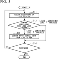
- Fig. 5 is a second flowchart showing a processing flow of the control device 1.
- control device 1 of the CO 2 recover device 100 may control the rich solution 91 before heat exchange, which will be put into the heat exchanger 4, to be delivered to the second absorption-solution delivery pipe 52 using the bypass pipe 55.
- the liquid level control part 15 may acquire the liquid level of the lean solution 92 from the level gauge L1 configured to detect the liquid level of the lean solution 92 (step S11).
- the liquid level control part 15 is configured to control the liquid level of the lean solution 92 to be set to a predetermined reference value.
- the liquid level control part 15 compares the liquid level of the lean solution 92 with a lower-limit threshold which is below the predetermined reference value by a predetermined value or more (step S12). Upon determining that the liquid level of the lean solution 92 to be equal to or less than the lower-limit threshold, the liquid level control part 15 instructs an opening for the valve-opening adjustment part 16 to increase the opening of the bypass control valve 63.
- the valve-opening adjustment part 16 controls the bypass control valve 63 to be changed from CLOSE to OPEN (step S13). Accordingly, it is possible to deliver the rich solution 91 to the second absorbent-solution deliver pipe 52 through the bypass pipe 55 when the liquid level is significantly lowered.
- the liquid level control part 15 determined whether to terminate the process (step S14), wherein the process will be resumed from step S11 unless the process is terminated.
- Fig. 6 is a third flowchart showing a processing flow of the control device 1.
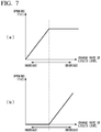
- Fig. 7 includes graphs showing the relationship between the openings and the liquid levels according to a function f ⁇ 1 and a function f ⁇ 2.
- the control device 1 may carry out a control according to a change rate of the liquid level of the lean solution 92.
- the liquid level control part 15 may acquire the liquid level of the lean solution 92 from the level gauge L1 configured to detect the liquid level of the lean solution 92 (step S21).
- the liquid level control part 15 is configured to control the liquid level of the lean solution 92 to be set to a predetermined reference value.
- the liquid level control part 15 determines a change rate of the liquid level of the lean solution 92 (step S22).
- the liquid level control part 15 may calculate an opening by inputting the current liquid level into the function f ⁇ 1 (see a graph of Fig.
- step S23 for calculating the opening of the rich-solution control valve 61 to be decreased linearly as the increasing rate of the liquid level becomes large.
- the liquid level control part 15 instructs the valve-opening adjustment part 16 to make a control to achieve the calculated opening.
- the valve-opening adjustment part 16 controls the rich-solution control valve 61 to have the instructed opening (step S24). Accordingly, it is possible to reduce the liquid level of the lean solution 92 over time since a flow rate per unit time of the rich solution 91 to flow into the regeneration tower 3 may decrease as the increasing rate of the liquid level becomes large.
- the liquid level control part 15 may calculate an opening by inputting the current liquid level into the function f ⁇ 2 (see a graph of Fig. 7(b) ) for calculating the opening of the bypass control valve 63 to be linearly increased as the decreasing rate of the liquid level becomes large (step S25).
- the liquid level control part 15 instructs the valve-opening adjustment part 16 to make a control to achieve the calculated opening.
- the valve-opening adjustment part 16 controls the bypass control valve 63 to have the instructed opening (step S26). Accordingly, it is possible to deliver the rich solution 91 to the second absorbent-solution deliver pipe 52 through the bypass pipe 55 as the decreasing rate of the liquid level becomes large.
- the liquid level control part 15 determines whether to terminate the process (step S27), wherein the process will be resumed from step S21 unless the process is terminated.
- control device 1 According to the aforementioned process of the control device 1, it is possible to make a control to stabilize the liquid level of the lean solution 92 in the lower section of the regeneration tower 3 in comparison with the conventional technology.
- the aforementioned control device includes a computer system.
- the foregoing processes are stored in computer-readable storage media in the form of programs, wherein a computer may read and execute programs to achieve the foregoing processes.
- computer-readable storage media refer to magnetic disks, magneto-optical disks, CD-ROM, DVD-ROM, and semiconductor memory.
- computer programs may be delivered to computers through communication lines, and therefore a computer may receive and execute programs.
- the foregoing programs may achieve part of the foregoing functions.
- the foregoing programs may be differential files (or differential programs) which can be combined with programs pre-installed in a computer system to achieve the foregoing functions.
Landscapes
- Chemical & Material Sciences (AREA)
- Engineering & Computer Science (AREA)
- Chemical Kinetics & Catalysis (AREA)
- Analytical Chemistry (AREA)
- General Chemical & Material Sciences (AREA)
- Oil, Petroleum & Natural Gas (AREA)
- Environmental & Geological Engineering (AREA)
- Biomedical Technology (AREA)
- Health & Medical Sciences (AREA)
- Organic Chemistry (AREA)
- Inorganic Chemistry (AREA)
- Sustainable Development (AREA)
- Life Sciences & Earth Sciences (AREA)
- Gas Separation By Absorption (AREA)
- Treating Waste Gases (AREA)
- Carbon And Carbon Compounds (AREA)
Abstract
Description
- The present invention relates to a CO2 recovery device and a CO2 recovery method.
- The present application claims the benefit of priority on Japanese Patent Application No.
2017-251925 filed on December 27, 2017 - CO2 devices configured to control CO2 emission by removing CO2 (carbon dioxide) from emission gas have been used in plants. In a CO2 recovery device, emission gas is brought into contact with an amine-based absorbent solution (hereinafter, referred to as an absorbent solution) in an absorption tower to produce a rich solution of an absorbent solution having absorbed CO2. Subsequently, the CO2 recovery device sends out a rich solution to a regeneration tower to isolate CO2 included in a rich salutation, to regenerate an absorbent solution, and to thereby circulate the absorbent solution to the absorption tower again. The CO2 recovery device may press the isolated CO2 gas into an oil field or may reserve the CO2 gas in an aquifer, thus preventing CO2 from being emitted into the atmosphere. In this connection,
Patent Document 1 discloses a related art. - Patent Document 1: Japanese Patent No.
5749677 - In the above CO2 recovery device, it is required to efficiently circulate an absorbent solution or a rich solution by reducing a failure rate of the device.
- The present invention aims to provide a CO2 recovery device and a CO2 recovery method, which can solve the above problem.
- In a first aspect of the present invention, a CO2 recovery device includes an absorption tower configured to bring an emission gas including CO2 in contact with an absorbent solution, to remove the CO2 from the emission gas, and to thereby generate a rich solution corresponding to the absorbent solution having absorbed the CO2; a regeneration tower configured to regenerate the absorbent solution by removing the CO2 from the rich solution; a heat exchanger configured to carry out heat exchange between the rich solution and the absorbent solution which is higher in temperature than the rich solution and from which the CO2 is removed; an absorbent-solution delivery pipe configured to deliver the absorbent solution subjected to the heat exchange in the heat exchanger to the absorption tower; and a bypass pipe configured to deliver the rich solution before the heat exchange, which will be introduced into the heat exchanger, to the absorbent-solution delivery pipe by controlling a bypass control valve.
- The CO2 recovery device may further include a first pressure measurement part configured to measure first pressure applied to the rich-solution delivery pipe configured to deliver the rich solution to the heat exchanger; and a bypass control part configured to increase the opening of the bypass control valve attached to the bypass pipe when the first pressure exceeds a predetermined threshold, thus delivering the rich solution before the heat exchange, which will be introduced into the heat exchanger, to the absorbent-solution delivery pipe.
- The CO2 recover device may further include a rich-solution delivery pipe configured to deliver the rich solution to the regeneration tower; a rich-solution control valve configured to adjust a flow rate of the rich solution, which is disposed adjacent to the regeneration tower rather than the heat exchanger configured to carry out the heat exchange between the rich solution flowing through the rich-solution delivery pipe and the absorbent solution; a liquid level measurement part configured to measure a liquid level of the absorbent solution accumulated in the base of the regeneration tower; and a liquid level control part configured to control the rich-solution control valve to increase its opening according to a reduction of the liquid level when a change rate of the liquid level shows an increasing trend but to control the bypass control valve to increase its opening according to a reduction of the liquid level when the change rate of the liquid level shows a deceasing trend.
- In a second aspect of the present invention, a CO2 recovery method for a CO2 recovery device includes the steps of: bringing an emission gas including CO2 in contact with an absorbent solution, removing the CO2 from the emission gas, and thereby generating a rich solution in an absorption tower; regenerating the absorbent solution by removing the CO2 from the rich solution in a regeneration tower; carrying out by a heat exchanger a heat exchange between the rich solution and the absorbent solution which is higher in temperature than the rich solution and from which the CO2 is removed; delivering by an absorbent-solution delivery pipe the absorbent solution subjected to the heat exchange in the heat exchanger to the absorption tower; and delivering by a bypass pipe the rich solution before the heat exchange in the heat exchanger to the absorbent-solution delivery pipe by controlling a bypass control valve.
- The CO2 recovery method may further includes the steps of: measuring by a first pressure measurement part a first pressure applied to the absorbent-solution delivery pipe configured to deliver the rich solution before the heat exchange, which will be introduced into the heat exchanger; and increasing by a bypass control part the opening of the bypass control valve attached to the bypass pipe when the first pressure exceeds a predetermined threshold, thus delivering the rich solution before the heat exchange, which will be introduced into the heat exchanger, to the absorbent-solution delivery pipe.
- The CO2 recovery method may further includes the steps of: delivering by a rich-solution delivery pipe the rich solution to the regeneration tower; adjusting a flow rate of the rich solution using a rich-solution control valve, which is disposed adjacent to the regeneration tower rather than the heat exchanger configured to carry out the heat exchange between the absorbent solution and the rich solution flowing through the rich-solution delivery pipe; measuring by a liquid level measurement part the liquid level of the absorbent solution accumulated in the base of the regeneration tower; and controlling by a liquid level control part the rich-solution control valve to increase its opening according to a reduction of the liquid level when a change rate of the liquid level shows an increasing trend while controlling the bypass control valve to increase its opening according to a reduction of the liquid level when the change rate of the liquid level shows a decreasing trend.
- According to the present invention, it is possible to reduce a failure rate so that a CO2 recover device can efficiently circulate an absorbent solution or a rich solution.
-
-
Fig. 1 is a schematic diagram of a CO2 recovery device according to one embodiment of the present invention. -
Fig. 2 is a block diagram showing a hardware configuration of a control device according to one embodiment of the present invention. -
Fig. 3 is a functional block diagram of the control device according to one embodiment of the present invention. -
Fig. 4 is a first flowchart showing a processing flow of the control device according to one embodiment of the present invention. -
Fig. 5 a second flowchart showing a processing flow of the control device according to one embodiment of the present invention. -
Fig. 6 is a third flowchart showing a processing flow of the control device according to one embodiment of the present invention. -
Fig. 7 includes graphs showing the relationship between openings and liquid levels according to a function f×1 and a function f×2. - Hereinafter, a CO2 recovery device according to one embodiment of the present invention will be described with reference to the drawings.
-
Fig. 1 is a schematic diagram of a CO2 recovery device of the present embodiment. - As shown in
Fig. 1 , a CO2 recovery device 100 mainly includes acontrol device 1, anabsorption tower 2, aregeneration tower 3, and aheat exchanger 4. -
Emission gas 80 emitted from industrial combustion facilities such as a boiler and a gas turbine will be sent to an emission-gas cooling device in which theemission gas 80 is cooled in cooling water and then sent to theabsorption tower 2 of the CO2 recovery device 100. In theabsorption tower 2, theemission gas 80 communicates and contacts with an absorbent solution based on an amine-based solution such that CO2 included in theemission gas 80 may be absorbed into the absorbent solution (a lean solution 92) in chemical reaction. An absorbent solution absorbing CO2 will be referred to as arich solution 91. Theemission gas 80 after removal of CO2 in theabsorption tower 2 will be discharged to the outside. Therich solution 91 is pressurized by a rich-solution delivery pump 21 and then sent out to theheat exchanger 4 through a first rich-solution delivery pipe 53. In theheat exchanger 4, therich solution 91 is heated by thelean solution 92 which is an absorbent solution regenerated by theregeneration tower 3 and which is higher in temperature than therich solution 91, and then the heatedrich solution 91 will be supplied to theregeneration tower 3 through a second rich-solution delivery pipe 54. - The
rich solution 91 supplied to theregeneration tower 3 will be emitted from the upper section of theregeneration tower 3 into its inside. Inside theregeneration tower 3, therich solution 91 may emit a majority of CO2 due to an endothermic reaction. An absorbent solution having emitted part or majority of CO2 in theregeneration tower 3 will be referred to as a semi-lean solution. When the semi-lean solution reaches the lower section of theregeneration tower 3, the semi-lean solution will be turned into the absorbent solution (i.e. the lean solution 92) from which roughly all of CO2 has been removed. In the lower section of theregeneration tower 3, the absorbent solution is heated by a reboiler such that CO2 included in the semi-lean solution may be emitted from the absorbent solution. Moisture is used as a heating source of a reboiler. Thelean solution 92 will be sent to theheat exchanger 4 through a first absorbent-solution delivery pipe 51. A CO2 gas 81 accompanied with moisture, which is emitted from therich solution 91 and the semi-lean solution in theregeneration tower 3, is derived from the upper section of theregeneration tower 3. The moisture included in the emitted CO2 gas 81 is condensed and sent back to theregeneration tower 3. In addition, the CO2 gas 81 is emitted to the outside and then recovered separately. The recovered CO2 gas 81 is pressed into an oil field using an enhanced oil recovery (EOR) or reserved in an aquifer, thus working out warming countermeasures. Thelean solution 92, which is sent out to theheat exchanger 4 through the first absorbent-solution delivery pipe 51, is cooled by therich solution 91 in theheat exchanger 4, and then the cooledlean solution 92 is supplied to theabsorption tower 2 through a second absorbent-solution delivery pipe 52. - A rich-
solution control valve 61 is attached to the second rich-solution delivery pipe 54. Thecontrol device 1 controls the rich-solution control valve 61 to control an amount ofrich solution 91 delivered to theregeneration tower 3 in each unit time. The liquid level (or the level) of thelean solution 92 reserved in the lower section of theregeneration tower 3 may be fluctuated due to a varying amount ofrich solution 91 delivered to theregeneration tower 3 in each unit time. A lean-solution control valve 62 is attached to the second absorbent-solution delivery pipe 52. Thecontrol device 1 controls the lean-solution control valve 62 to control an amount oflean solution 92 delivered to theabsorption tower 2 in each unit time. - A rich-
solution delivery pump 21 is attached to the first rich-solution delivery pipe 53. Thecontrol device 1 controls the rich-solution delivery pump 21 such that therich solution 91 reserved in the lower section of theabsorption tower 2 can be forcedly delivered to theheat exchanger 4 and theregeneration tower 3. A lean-solution delivery pump 31 is attached to the first absorbent-solution delivery pipe 51. Thecontrol device 1 controls the lean-solution delivery pump 31 such that thelean solution 92 reserved in the lower section of theregeneration tower 3 can be forcedly delivered to theheat exchanger 4 and theabsorption tower 2. - According to the present embodiment, the CO2 recovery device 100 provides a
bypass pipe 55 connected between the first rich-solution delivery pipe 53 and the second absorbent-solution delivery pipe 52. Abypass control valve 63 is attached to thebypass pipe 55. Thecontrol device 1 controls thebypass control valve 63 to be opened such that therich solution 91 prior to heat exchange, which will be applied to theheat exchanger 4, can be delivered to the second absorbent-solution delivery pipe 52. - The
control device 1 may cause therich solution 91 and thelean solution 92 to circulate in the CO2 recovery device 100 by controlling the pressed delivery of therich solution 91 via the rich-solution deliverpump 21, the pressed delivery of thelean solution 92 via the lean-solution delivery pump 31, the opening of the rich-solution control valve 61, and the opening of the lean-solution control valve 62. Specifically, thecontrol device 1 acquires a flow rate per unit time which is obtained from a rich-solution flowmeter 71 and a lean-solution flowmeter 72, the liquid level of thelean solution 2 in the lower section of theregeneration tower 3, the liquid level of therich solution 91 in the lower section of theabsorption tower 2, and a load value (or an output value) of an industrial combustion facility such as a boiler and a gas turbine, and therefore thecontrol device 1 may control the pressed delivery of therich solution 91 via the rich-solution deliverpump 21, the pressed delivery of thelean solution 92 via the lean-solution delivery pump 31, the opening of the rich-solution control valve 61, and the opening of the lean-solution control valve 62 based on those pieces of information. - A level gauge L1 configured to detect the liquid level of the
lean solution 92 is attached to the lower section of theregeneration tower 3. An excessive descending of the liquid level of thelean solution 92 in the lower section of theregeneration tower 3 may likely cause a failure such as cavitation due to an incapacity of the lean-solution delivery pump 31 to sufficiently deliver thelean solution 92. Therefore, it is required that the liquid level be set to a reference position. Thecontrol device 1 measures the liquid level of thelean solution 92 in the lower section of theregeneration tower 3 based on a measurement of the level gauge L1, and therefore thecontrol device 1 carries out a feedback control for the opening of the rich-solution control valve 61 to thereby fix the liquid level. Specifically, thecontrol device 1 decreases the opening of the rich-solution control valve 61 in preparation for a reduction of a flow rate of therich solution 91 per unit time to be forcedly delivered from theabsorption tower 2 via the rich-solution delivery pump 21 due to a reduction of load. This may increase the pressure of the first rich-solution delivery pipe 53. A pressure gauge PI measures the pressure of the first rich-solution pipe 53 to output its measurement to thecontrol device 1. A malfunction such as a failure of theheat exchanger 4 may occur when theheat exchanger 4 bears a load of pressure due to an increased pressure applied to the first rich-solution delivery pipe 53. For this reason, as described above, the CO2 recovery device 100 of the present embodiment provides thebypass pipe 55, by which the rich-solution 91 is brought into the second absorbent-solution delivery pipe 52 when thecontrol device 1 controls thebypass control valve 63 from CLOSE to OPEN. This may reduce the pressure of the first rich-solution delivery pipe 53, and therefore it is possible to allay a fear of causing a failure of theheat exchanger 4. -
Fig. 2 is a block diagram showing the hardware configuration of thecontrol device 1 of the present embodiment. - The
control device 1 is a computer, as shown inFig. 2 , which includes various hardware elements such as aCPU 101, a ROM (Read-Only Memory) 102, a RAM (Random-Access Memory) 103, a storage unit such as a HDD (Hard-Disk Drive) 104, auser interface 105 such as a touch panel, and acommunication module 106 to communicate with sensors. -
Fig. 3 is a functional block diagram of thecontrol device 1 of the present embodiment. - The
CPU 101 of thecontrol device 1 may execute preinstalled control programs after starting the operation of thecontrol device 1. Thus, thecontrol device 1 may realize acontroller 11, apressure measurement part 12, a liquidlevel measurement part 13, abypass control part 14, a liquidlevel control part 15, a valve-opening adjustment part 16, an absorbent-solution-flow measurement part 17, and an absorbent-solution-flow adjustment part 18. - The
controller 11 is configured to control various functional parts of thecontrol device 1. - The
pressure measurement part 12 is configured to measure the pressure of a predetermined pipe such as the pressure of the second rich-solution delivery pipe 54 configured to deliver therich solution 91 to theheat exchanger 4. - The liquid-
surface measurement part 13 is configured to measure the liquid level of thelean solution 92 accumulated in the base of theregeneration tower 3. - The absorbent-solution-
flow measurement part 17 is configured to measure a flow rate per unit time given by the rich-solution flowmeter 71 and the lean-solution flowmeter 72. - The
bypass control part 14 may instruct the valve-opening adjustment part 16 to increase the opening of thebypass control valve 63 when the pressure measured by thepressure measurement part 12 exceeds a predetermined threshold. As a result, thebypass control part 14 controls therich solution 91 before heat exchange, which will be sent to theheat exchanger 4, to be delivered to the second absorbent-solution delivery pipe 52. - The liquid
level control part 15 may instruct the absorbent-solution-flow adjustment part 18 to increase the opening of the rich-solution control valve 61 according to a reduction of the liquid level when the liquid level of thelean solution 92 accumulated in the bottom of theregeneration tower 4 is equal to or above a predetermine position. The liquidlevel control part 15 may instruct the absorbent-solution-flow adjustment part 18 to increase the opening of thebypass control valve 63 according to a reduction of the liquid level when the liquid level of thelean solution 92 accumulated in the base of theregeneration tower 3 is below a predetermined position. - The absorbent-solution-
flow adjustment part 18 is configured to calculate the opening of the rich-solution control valve 61 and the opening of the lean-solution control valve 62 such that a flow rate measured by the absorbent-solution-flow measurement part 17 may reach a predetermined target value. The liquidlevel control part 15 may determine a target value for a rich-solution flow rate. - The valve-
opening adjustment part 16 is configured to control the opening of the rich-solution control valve 61 and the opening of thebypass control valve 63 according to instructions from thebypass control part 14 and the absorbent-solution-flow adjustment part 18. -
Fig. 4 is a first flowchart showing a processing flow of thecontrol device 1. - It is necessary to realize a fear that an excessive load may be imparted to the
heat exchanger 4 due to an increasing pressure of the first rich-solution delivery pipe 53. Thecontrol device 1 is designed to reduce a load of pressure imparted to theheat exchanger 4 according to the following process. - First, the
pressure measurement part 12 of thecontrol device 1 acquires a measurement a from the pressure gauge PI (step S1). Thebypass controller 14 compares the measurement a with a threshold b of pressure (step S2). For example, the threshold b is produced by adding a predetermined value to pressure c of the first rich-solution delivery pipe 53 in its setting (b>c). The absorbent-solution-flow measurement part 17 measures a flow rate per unit time using the rich-solution flowmeter 71 and the lean-solution flowmeter 72, and therefore the absorbent-solution-flow adjustment part 18 acquires the measurement result. The absorbent-solution-flow adjustment part 18 controls the opening of the rich-solution control valve 61 and the opening of the lean-solution control valve 62 such that the flow rate per unit time, which is obtained from the rich-solution flowmeter 71 or the lean-solution flowmeter 72, may match a predetermined value. Herein, the opening control would be a circulation control for therich solution 91 and thelean solution 92. It is assumed that the absorbent-solution-flow adjustment part 18 would instruct the valve-opening adjustment part 16 to decrease the opening of the rich-solution control valve 61. Accordingly, the valve-opening adjustment part 16 may decrease the opening of the rich-solution control valve 61 to the instructed opening. This may establish a relationship of "measurement a > threshold b" with respect to the pressure of the first rich-solution delivery pipe 53. - Upon determining through the above comparison that the measurement a exceeds the threshold b, the
bypass control part 14 determines to carry out a bypass control. Thebypass control part 14 instructs the valve-opening adjustment part 16 to change thebypass control valve 63 from OPEN to CLOSE (step S3). Thebypass control part 14 may give an opening instruction to the valve-opening adjustment part 16 such that the opening of thebypass control valve 63 will be increased as the measurement a becomes a larger value; hence, the valve-opening adjustment part 16 may control the opening of thebypass control valve 63 according to the opening instruction. Thebypass control part 14 determines to terminate the process (step S4), wherein the process will be resumed from step S1 unless the process is terminated. - According to the above process, it is possible for the
control device 1 to reduce a load of pressure imparted to theheat exchanger 4 due to an increasing pressure applied to the first rich-solution delivery pipe 53. In addition, thecontrol device 1 may constitute a minimum flowline using thebypass pipe 55, and therefore even when the rich-solution control valve 61 would be fully closed due to some reasons, it is possible to automatically circulate therich solution 91 through the minimum flowline configured of thebypass pipe 55 adjacent to theabsorption tower 2 by opening thebypass control valve 63. - In this connection, it is possible to attach a pressure gauge P2 to the first absorbent-
solution delivery pipe 51 in the CO2 recovery device 100, and therefore thecontrol device 1 may control therich solution 91 before heat exchange, which will be put into theheat exchanger 4, to be delivered to the second absorbent-solution delivery pipe 52 using the measurement a of the pressure gauge PI as well as a measurement d of the pressure gauge P2. - Specifically, the
bypass control part 14 obtains the measurement a from the pressure gauge PI while obtaining the measurement d from the pressure gauge P2. Subsequently, when "measurement a > measurement d + α", thebypass control part 14 may instruct the valve-opening adjustment part 16 to change thebypass control valve 63 from CLOSE to OPEN. - Similar to the aforementioned effect, it is possible to reduce a load of pressure imparted to the
heat exchanger 4 due to an increasing pressure applied to the first rich-solution delivery pipe 53. -
Fig. 5 is a second flowchart showing a processing flow of thecontrol device 1. - In the CO2 recovery device 100, it takes several minutes for the
lean solution 92, corresponding to therich solution 92 having removed CO2 therefrom, to reach the lower section of theregeneration tower 3. For this reason, it is difficult to stabilize the liquid level of thelean solution 92 in the lower section of theregeneration tower 3. To solve this problem, thecontrol device 1 of the CO2 recoverdevice 100 according to the second embodiment may control therich solution 91 before heat exchange, which will be put into theheat exchanger 4, to be delivered to the second absorption-solution delivery pipe 52 using thebypass pipe 55. - Specifically, the liquid
level control part 15 may acquire the liquid level of thelean solution 92 from the level gauge L1 configured to detect the liquid level of the lean solution 92 (step S11). The liquidlevel control part 15 is configured to control the liquid level of thelean solution 92 to be set to a predetermined reference value. The liquidlevel control part 15 compares the liquid level of thelean solution 92 with a lower-limit threshold which is below the predetermined reference value by a predetermined value or more (step S12). Upon determining that the liquid level of thelean solution 92 to be equal to or less than the lower-limit threshold, the liquidlevel control part 15 instructs an opening for the valve-opening adjustment part 16 to increase the opening of thebypass control valve 63. The valve-opening adjustment part 16 controls thebypass control valve 63 to be changed from CLOSE to OPEN (step S13). Accordingly, it is possible to deliver therich solution 91 to the second absorbent-solution deliverpipe 52 through thebypass pipe 55 when the liquid level is significantly lowered. This makes therich solution 92 flow into the second absorbent-solution delivery pipe 52 so as to decrease a flow rate per unit time for thelean solution 92 to flow from the first absorbent-solution deliverpipe 51 to the second absorbent-solution deliverpipe 52, thus decreasing an amount of emission per unit time for emitting thelean solution 92 from the lower section of theregeneration tower 3. Due to a good response in decreasing the amount of emission, it is possible to rapidly increase the liquid level of thelean solution 92. The liquidlevel control part 15 determined whether to terminate the process (step S14), wherein the process will be resumed from step S11 unless the process is terminated. -
Fig. 6 is a third flowchart showing a processing flow of thecontrol device 1. -
Fig. 7 includes graphs showing the relationship between the openings and the liquid levels according to a function f×1 and a function f×2. - As described below, the
control device 1 may carry out a control according to a change rate of the liquid level of thelean solution 92. Specifically, the liquidlevel control part 15 may acquire the liquid level of thelean solution 92 from the level gauge L1 configured to detect the liquid level of the lean solution 92 (step S21). The liquidlevel control part 15 is configured to control the liquid level of thelean solution 92 to be set to a predetermined reference value. The liquidlevel control part 15 determines a change rate of the liquid level of the lean solution 92 (step S22). When the change rate of the liquid level shows an increasing trend, the liquidlevel control part 15 may calculate an opening by inputting the current liquid level into the function f×1 (see a graph ofFig. 7(a) ) for calculating the opening of the rich-solution control valve 61 to be decreased linearly as the increasing rate of the liquid level becomes large (step S23). The liquidlevel control part 15 instructs the valve-opening adjustment part 16 to make a control to achieve the calculated opening. The valve-opening adjustment part 16 controls the rich-solution control valve 61 to have the instructed opening (step S24). Accordingly, it is possible to reduce the liquid level of thelean solution 92 over time since a flow rate per unit time of therich solution 91 to flow into theregeneration tower 3 may decrease as the increasing rate of the liquid level becomes large. - On the other hand, when the change rate of the liquid level shows a decreasing trend, the liquid
level control part 15 may calculate an opening by inputting the current liquid level into the function f×2 (see a graph ofFig. 7(b) ) for calculating the opening of thebypass control valve 63 to be linearly increased as the decreasing rate of the liquid level becomes large (step S25). The liquidlevel control part 15 instructs the valve-opening adjustment part 16 to make a control to achieve the calculated opening. The valve-opening adjustment part 16 controls thebypass control valve 63 to have the instructed opening (step S26). Accordingly, it is possible to deliver therich solution 91 to the second absorbent-solution deliverpipe 52 through thebypass pipe 55 as the decreasing rate of the liquid level becomes large. This may decrease a flow rate per unit time of thelean solution 92 to flow from the first absorbent-solution deliverpipe 51 to the second absorbent-solution deliverpipe 52, thus decreasing an amount of emission per unit time for emitting thelean solution 92 from the lower section of theregeneration tower 3. Due to a good response in decreasing the amount of emission, it is possible to rapidly increase the liquid level of thelean solution 92. The liquidlevel control part 15 determines whether to terminate the process (step S27), wherein the process will be resumed from step S21 unless the process is terminated. - According to the aforementioned process of the
control device 1, it is possible to make a control to stabilize the liquid level of thelean solution 92 in the lower section of theregeneration tower 3 in comparison with the conventional technology. - The aforementioned control device includes a computer system. The foregoing processes are stored in computer-readable storage media in the form of programs, wherein a computer may read and execute programs to achieve the foregoing processes. Herein, computer-readable storage media refer to magnetic disks, magneto-optical disks, CD-ROM, DVD-ROM, and semiconductor memory. In addition, computer programs may be delivered to computers through communication lines, and therefore a computer may receive and execute programs.
- The foregoing programs may achieve part of the foregoing functions. In addition, the foregoing programs may be differential files (or differential programs) which can be combined with programs pre-installed in a computer system to achieve the foregoing functions.
-
- 100
- CO2 recovery device
- 1
- control device
- 2
- absorption tower
- 3
- regeneration tower
- 4
- heat exchanger
- 11
- controller
- 12
- pressure measurement part
- 13
- liquid level measurement part
- 14
- bypass control part
- 15
- liquid level control part
- 16
- valve-opening adjustment part
- 51
- first absorbent-solution delivery pipe
- 52
- second absorbent-solution delivery pipe
- 53
- first rich-solution delivery pipe
- 54
- second rich-solution delivery pipe
- 61
- rich-solution control valve
- 62
- lean-solution control valve
- 63
- bypass control valve
Claims (6)
- A CO2 recovery device comprising:an absorption tower configured to bring an emission gas including CO2 in contact with an absorbent solution, to remove the CO2 from the emission gas, and to thereby generate a rich solution corresponding to the absorbent solution having absorbed the CO2;a regeneration tower configured to regenerate the absorbent solution by removing the CO2 from the rich solution;a heat exchanger configured to carry out heat exchange between the rich solution and the absorbent solution which is higher in temperature than the rich solution and from which the CO2 is removed;an absorbent-solution delivery pipe configured to deliver the absorbent solution subjected to the heat exchange in the heat exchanger to the absorption tower; anda bypass pipe configured to deliver the rich solution before the heat exchange, which is to be introduced into the heat exchanger, to the absorbent-solution delivery pipe by controlling a bypass control valve.
- The CO2 recovery device according to claim 1, further comprising:a first pressure measurement part configured to measure first pressure applied to the rich-solution delivery pipe configured to deliver the rich solution to the heat exchanger; anda bypass control part configured to increase the opening of the bypass control valve attached to the bypass pipe when the first pressure exceeds a predetermined threshold, thus delivering the rich solution before the heat exchange, which is to be introduced into the heat exchanger, to the absorbent-solution delivery pipe.
- The CO2 recover device according to claim 1 or 2, further comprising:a rich-solution delivery pipe configured to deliver the rich solution to the regeneration tower;a rich-solution control valve configured to adjust a flow rate of the rich solution, which is disposed adjacent to the regeneration tower rather than the heat exchanger configured to carry out the heat exchange between the rich solution flowing through the rich-solution delivery pipe and the absorbent solution;a liquid level measurement part configured to measure a liquid level of the absorbent solution accumulated in the base of the regeneration tower; anda liquid level control part configured to control the rich-solution control valve to increase its opening according to a reduction of the liquid level when a change rate of the liquid level shows an increasing trend but to control the bypass control valve to increase its opening according to a reduction of the liquid level when the change rate of the liquid level shows a deceasing trend.
- A CO2 recovery method for a CO2 recovery device, comprising:bringing an emission gas including CO2 in contact with an absorbent solution, removing the CO2 from the emission gas, and thereby generating a rich solution in an absorption tower;regenerating the absorbent solution by removing the CO2 from the rich solution in a regeneration tower;carrying out by a heat exchanger a heat exchange between the rich solution and the absorbent solution which is higher in temperature than the rich solution and from which the CO2 is removed;delivering by an absorbent-solution delivery pipe the absorbent solution subjected to the heat exchange in the heat exchanger to the absorption tower; anddelivering by a bypass pipe the rich solution before the heat exchange in the heat exchanger to the absorbent-solution delivery pipe by controlling a bypass control valve.
- The CO2 recovery method according to claim 4, further comprising:measuring by a first pressure measurement part a first pressure applied to the absorbent-solution delivery pipe configured to deliver the rich solution before the heat exchange, which is to be introduced into the heat exchanger; andincreasing by a bypass control part the opening of the bypass control valve attached to the bypass pipe when the first pressure exceeds a predetermined threshold, thus delivering the rich solution before the heat exchange, which is to be introduced into the heat exchanger, to the absorbent-solution delivery pipe.
- The CO2 recovery method according to claim 4 or 5, further comprising:delivering by a rich-solution delivery pipe the rich solution to the regeneration tower;adjusting a flow rate of the rich solution using a rich-solution control valve, which is disposed adjacent to the regeneration tower rather than the heat exchanger configured to carry out the heat exchange between the absorbent solution and the rich solution flowing through the rich-solution delivery pipe;measuring by a liquid level measurement part the liquid level of the absorbent solution accumulated in the base of the regeneration tower; andcontrolling by a liquid level control part the rich-solution control valve to increase its opening according to a reduction of the liquid level when a change rate of the liquid level shows an increasing trend while controlling the bypass control valve to increase its opening according to a reduction of the liquid level when the change rate of the liquid level shows a decreasing trend.
Applications Claiming Priority (2)
| Application Number | Priority Date | Filing Date | Title |
|---|---|---|---|
| JP2017251925A JP7043249B2 (en) | 2017-12-27 | 2017-12-27 | CO2 recovery device, CO2 recovery method |
| PCT/JP2018/047811 WO2019131747A1 (en) | 2017-12-27 | 2018-12-26 | Co2 recovery device and co2 recovery method |
Publications (3)
| Publication Number | Publication Date |
|---|---|
| EP3744417A1 true EP3744417A1 (en) | 2020-12-02 |
| EP3744417A4 EP3744417A4 (en) | 2021-09-29 |
| EP3744417B1 EP3744417B1 (en) | 2025-03-26 |
Family
ID=67063736
Family Applications (1)
| Application Number | Title | Priority Date | Filing Date |
|---|---|---|---|
| EP18895054.7A Active EP3744417B1 (en) | 2017-12-27 | 2018-12-26 | Co2 recovery device and co2 recovery method |
Country Status (5)
| Country | Link |
|---|---|
| US (1) | US11229873B2 (en) |
| EP (1) | EP3744417B1 (en) |
| JP (1) | JP7043249B2 (en) |
| CA (1) | CA3085415C (en) |
| WO (1) | WO2019131747A1 (en) |
Cited By (1)
| Publication number | Priority date | Publication date | Assignee | Title |
|---|---|---|---|---|
| EP3944890B1 (en) | 2020-07-29 | 2023-09-06 | IFP Energies nouvelles | Method and system for pretreatment of gaseous effluent for capturing post-combustion co2 |
Families Citing this family (5)
| Publication number | Priority date | Publication date | Assignee | Title |
|---|---|---|---|---|
| CN113418825A (en) * | 2021-06-24 | 2021-09-21 | 中国核动力研究设计院 | Carbon dioxide eliminating agent eliminating performance test system and test method |
| JP2024115682A (en) * | 2023-02-15 | 2024-08-27 | 三菱重工業株式会社 | Co2 recovery device and control method |
| CN116747674A (en) * | 2023-04-25 | 2023-09-15 | 河南农业大学 | A biohydrogen decarbonization purification device based on deep eutectic solvent |
| JP2025062825A (en) * | 2023-10-03 | 2025-04-15 | 株式会社神戸製鋼所 | Gas treatment device and gas treatment method |
| JP2025069890A (en) * | 2023-10-18 | 2025-05-01 | 三菱重工業株式会社 | Regeneration tower, control device and control method |
Family Cites Families (12)
| Publication number | Priority date | Publication date | Assignee | Title |
|---|---|---|---|---|
| JPS5584491A (en) | 1978-12-15 | 1980-06-25 | Kurita Water Ind Ltd | Pitch attachment preventing agent for paper making |
| US7718151B1 (en) * | 2006-04-07 | 2010-05-18 | Liang Hu | Methods and systems for deacidizing gaseous mixtures |
| AU2009216164B2 (en) | 2008-02-22 | 2011-10-13 | Mitsubishi Heavy Industries, Ltd. | Apparatus for recovering CO2 and method of recovering CO2 |
| JP2010201379A (en) | 2009-03-04 | 2010-09-16 | Toshiba Corp | Carbon dioxide recovery system |
| JP5479949B2 (en) | 2009-04-08 | 2014-04-23 | 株式会社東芝 | Measuring device, measuring method, and carbon dioxide recovery system |
| JP5383338B2 (en) | 2009-06-17 | 2014-01-08 | 三菱重工業株式会社 | CO2 recovery device and CO2 recovery method |
| DE102010013729A1 (en) | 2010-03-31 | 2011-10-06 | Siemens Aktiengesellschaft | Method and apparatus for separating carbon dioxide from an exhaust gas of a fossil-fired power plant |
| JP5720463B2 (en) | 2011-07-21 | 2015-05-20 | 株式会社Ihi | Carbon dioxide recovery method and recovery apparatus |
| JP5749677B2 (en) | 2012-03-28 | 2015-07-15 | 株式会社東芝 | Carbon dioxide recovery system and control method thereof |
| JP6180793B2 (en) | 2012-06-20 | 2017-08-16 | 株式会社東芝 | Carbon dioxide recovery device and carbon dioxide recovery method |
| KR101534710B1 (en) * | 2013-11-12 | 2015-07-07 | 현대자동차 주식회사 | Device for absorbing and separating acid gases |
| US10946330B2 (en) * | 2018-02-06 | 2021-03-16 | Saudi Arabian Oil Company | System and method for removing acid gas from a sour gas stream |
-
2017
- 2017-12-27 JP JP2017251925A patent/JP7043249B2/en active Active
-
2018
- 2018-12-26 US US16/771,118 patent/US11229873B2/en active Active
- 2018-12-26 EP EP18895054.7A patent/EP3744417B1/en active Active
- 2018-12-26 WO PCT/JP2018/047811 patent/WO2019131747A1/en not_active Ceased
- 2018-12-26 CA CA3085415A patent/CA3085415C/en active Active
Cited By (1)
| Publication number | Priority date | Publication date | Assignee | Title |
|---|---|---|---|---|
| EP3944890B1 (en) | 2020-07-29 | 2023-09-06 | IFP Energies nouvelles | Method and system for pretreatment of gaseous effluent for capturing post-combustion co2 |
Also Published As
| Publication number | Publication date |
|---|---|
| CA3085415C (en) | 2022-06-21 |
| US11229873B2 (en) | 2022-01-25 |
| JP2019115896A (en) | 2019-07-18 |
| JP7043249B2 (en) | 2022-03-29 |
| WO2019131747A1 (en) | 2019-07-04 |
| EP3744417B1 (en) | 2025-03-26 |
| CA3085415A1 (en) | 2019-07-04 |
| EP3744417A4 (en) | 2021-09-29 |
| US20200368672A1 (en) | 2020-11-26 |
Similar Documents
| Publication | Publication Date | Title |
|---|---|---|
| EP3744417B1 (en) | Co2 recovery device and co2 recovery method | |
| AU2010200176B2 (en) | CO2 recovering apparatus and method | |
| EP3020463B1 (en) | Carbon dioxide capture apparatus and method of capturing carbon dioxide | |
| US10173166B2 (en) | Carbon dioxide recovering apparatus and method for operating the same | |
| US9186620B2 (en) | CO2 recovery device | |
| AU2015203510B2 (en) | Carbon dioxide separation and capture apparatus and method of controlling operation of carbon dioxide separation and capture apparatus | |
| CN106943844B (en) | Carbon dioxide separation and capture device and method of controlling operation of carbon dioxide separation and capture device | |
| CN104096455B (en) | Carbon dioxide recovery system and method of operation thereof | |
| CN112473322A (en) | Carbon dioxide recovery system and method for operating same | |
| JP2010100491A (en) | Device and method for carbon dioxide recovery | |
| JP2011005367A (en) | Co2 recovering apparatus and method | |
| JP5578125B2 (en) | Non-condensable gas processing equipment | |
| JP2014188485A (en) | Anaerobic treatment method | |
| JP2019506557A (en) | Reducing agent supply system and control method thereof | |
| JP2008267742A (en) | Boiler drum level control method and apparatus | |
| JP2024002180A (en) | Organic matter treatment system | |
| JP2014173345A (en) | Method and device for preventing non-condensed gas retention |
Legal Events
| Date | Code | Title | Description |
|---|---|---|---|
| STAA | Information on the status of an ep patent application or granted ep patent |
Free format text: STATUS: THE INTERNATIONAL PUBLICATION HAS BEEN MADE |
|
| PUAI | Public reference made under article 153(3) epc to a published international application that has entered the european phase |
Free format text: ORIGINAL CODE: 0009012 |
|
| STAA | Information on the status of an ep patent application or granted ep patent |
Free format text: STATUS: REQUEST FOR EXAMINATION WAS MADE |
|
| 17P | Request for examination filed |
Effective date: 20200609 |
|
| AK | Designated contracting states |
Kind code of ref document: A1 Designated state(s): AL AT BE BG CH CY CZ DE DK EE ES FI FR GB GR HR HU IE IS IT LI LT LU LV MC MK MT NL NO PL PT RO RS SE SI SK SM TR |
|
| AX | Request for extension of the european patent |
Extension state: BA ME |
|
| DAV | Request for validation of the european patent (deleted) | ||
| DAX | Request for extension of the european patent (deleted) | ||
| A4 | Supplementary search report drawn up and despatched |
Effective date: 20210831 |
|
| RIC1 | Information provided on ipc code assigned before grant |
Ipc: C01B 32/50 20170101ALI20210825BHEP Ipc: B01D 53/96 20060101ALI20210825BHEP Ipc: B01D 53/78 20060101ALI20210825BHEP Ipc: B01D 53/14 20060101ALI20210825BHEP Ipc: B01D 53/62 20060101AFI20210825BHEP |
|
| STAA | Information on the status of an ep patent application or granted ep patent |
Free format text: STATUS: EXAMINATION IS IN PROGRESS |
|
| 17Q | First examination report despatched |
Effective date: 20230912 |
|
| RAP1 | Party data changed (applicant data changed or rights of an application transferred) |
Owner name: MITSUBISHI HEAVY INDUSTRIES, LTD. |
|
| GRAP | Despatch of communication of intention to grant a patent |
Free format text: ORIGINAL CODE: EPIDOSNIGR1 |
|
| STAA | Information on the status of an ep patent application or granted ep patent |
Free format text: STATUS: GRANT OF PATENT IS INTENDED |
|
| INTG | Intention to grant announced |
Effective date: 20240807 |
|
| GRAJ | Information related to disapproval of communication of intention to grant by the applicant or resumption of examination proceedings by the epo deleted |
Free format text: ORIGINAL CODE: EPIDOSDIGR1 |
|
| STAA | Information on the status of an ep patent application or granted ep patent |
Free format text: STATUS: EXAMINATION IS IN PROGRESS |
|
| GRAP | Despatch of communication of intention to grant a patent |
Free format text: ORIGINAL CODE: EPIDOSNIGR1 |
|
| STAA | Information on the status of an ep patent application or granted ep patent |
Free format text: STATUS: GRANT OF PATENT IS INTENDED |
|
| INTC | Intention to grant announced (deleted) | ||
| INTG | Intention to grant announced |
Effective date: 20241017 |
|
| P01 | Opt-out of the competence of the unified patent court (upc) registered |
Free format text: CASE NUMBER: APP_63355/2024 Effective date: 20241128 |
|
| GRAS | Grant fee paid |
Free format text: ORIGINAL CODE: EPIDOSNIGR3 |
|
| GRAA | (expected) grant |
Free format text: ORIGINAL CODE: 0009210 |
|
| STAA | Information on the status of an ep patent application or granted ep patent |
Free format text: STATUS: THE PATENT HAS BEEN GRANTED |
|
| AK | Designated contracting states |
Kind code of ref document: B1 Designated state(s): AL AT BE BG CH CY CZ DE DK EE ES FI FR GB GR HR HU IE IS IT LI LT LU LV MC MK MT NL NO PL PT RO RS SE SI SK SM TR |
|
| REG | Reference to a national code |
Ref country code: GB Ref legal event code: FG4D |
|
| REG | Reference to a national code |
Ref country code: CH Ref legal event code: EP |
|
| REG | Reference to a national code |
Ref country code: DE Ref legal event code: R096 Ref document number: 602018080589 Country of ref document: DE |
|
| REG | Reference to a national code |
Ref country code: IE Ref legal event code: FG4D |
|
| REG | Reference to a national code |
Ref country code: NL Ref legal event code: FP |
|
| PG25 | Lapsed in a contracting state [announced via postgrant information from national office to epo] |
Ref country code: RS Free format text: LAPSE BECAUSE OF FAILURE TO SUBMIT A TRANSLATION OF THE DESCRIPTION OR TO PAY THE FEE WITHIN THE PRESCRIBED TIME-LIMIT Effective date: 20250626 |
|
| PG25 | Lapsed in a contracting state [announced via postgrant information from national office to epo] |
Ref country code: FI Free format text: LAPSE BECAUSE OF FAILURE TO SUBMIT A TRANSLATION OF THE DESCRIPTION OR TO PAY THE FEE WITHIN THE PRESCRIBED TIME-LIMIT Effective date: 20250326 |
|
| REG | Reference to a national code |
Ref country code: LT Ref legal event code: MG9D |
|
| PG25 | Lapsed in a contracting state [announced via postgrant information from national office to epo] |
Ref country code: HR Free format text: LAPSE BECAUSE OF FAILURE TO SUBMIT A TRANSLATION OF THE DESCRIPTION OR TO PAY THE FEE WITHIN THE PRESCRIBED TIME-LIMIT Effective date: 20250326 |
|
| PG25 | Lapsed in a contracting state [announced via postgrant information from national office to epo] |
Ref country code: LV Free format text: LAPSE BECAUSE OF FAILURE TO SUBMIT A TRANSLATION OF THE DESCRIPTION OR TO PAY THE FEE WITHIN THE PRESCRIBED TIME-LIMIT Effective date: 20250326 |
|
| PG25 | Lapsed in a contracting state [announced via postgrant information from national office to epo] |
Ref country code: GR Free format text: LAPSE BECAUSE OF FAILURE TO SUBMIT A TRANSLATION OF THE DESCRIPTION OR TO PAY THE FEE WITHIN THE PRESCRIBED TIME-LIMIT Effective date: 20250627 Ref country code: BG Free format text: LAPSE BECAUSE OF FAILURE TO SUBMIT A TRANSLATION OF THE DESCRIPTION OR TO PAY THE FEE WITHIN THE PRESCRIBED TIME-LIMIT Effective date: 20250326 |
|
| PG25 | Lapsed in a contracting state [announced via postgrant information from national office to epo] |
Ref country code: SE Free format text: LAPSE BECAUSE OF FAILURE TO SUBMIT A TRANSLATION OF THE DESCRIPTION OR TO PAY THE FEE WITHIN THE PRESCRIBED TIME-LIMIT Effective date: 20250326 |
|
| REG | Reference to a national code |
Ref country code: AT Ref legal event code: MK05 Ref document number: 1778514 Country of ref document: AT Kind code of ref document: T Effective date: 20250326 |
|
| PG25 | Lapsed in a contracting state [announced via postgrant information from national office to epo] |
Ref country code: SM Free format text: LAPSE BECAUSE OF FAILURE TO SUBMIT A TRANSLATION OF THE DESCRIPTION OR TO PAY THE FEE WITHIN THE PRESCRIBED TIME-LIMIT Effective date: 20250326 |
|
| PG25 | Lapsed in a contracting state [announced via postgrant information from national office to epo] |
Ref country code: ES Free format text: LAPSE BECAUSE OF FAILURE TO SUBMIT A TRANSLATION OF THE DESCRIPTION OR TO PAY THE FEE WITHIN THE PRESCRIBED TIME-LIMIT Effective date: 20250326 Ref country code: PT Free format text: LAPSE BECAUSE OF FAILURE TO SUBMIT A TRANSLATION OF THE DESCRIPTION OR TO PAY THE FEE WITHIN THE PRESCRIBED TIME-LIMIT Effective date: 20250728 |
|
| PG25 | Lapsed in a contracting state [announced via postgrant information from national office to epo] |
Ref country code: PL Free format text: LAPSE BECAUSE OF FAILURE TO SUBMIT A TRANSLATION OF THE DESCRIPTION OR TO PAY THE FEE WITHIN THE PRESCRIBED TIME-LIMIT Effective date: 20250326 |
|
| PG25 | Lapsed in a contracting state [announced via postgrant information from national office to epo] |
Ref country code: AT Free format text: LAPSE BECAUSE OF FAILURE TO SUBMIT A TRANSLATION OF THE DESCRIPTION OR TO PAY THE FEE WITHIN THE PRESCRIBED TIME-LIMIT Effective date: 20250326 |
|
| PG25 | Lapsed in a contracting state [announced via postgrant information from national office to epo] |
Ref country code: EE Free format text: LAPSE BECAUSE OF FAILURE TO SUBMIT A TRANSLATION OF THE DESCRIPTION OR TO PAY THE FEE WITHIN THE PRESCRIBED TIME-LIMIT Effective date: 20250326 |
|
| PG25 | Lapsed in a contracting state [announced via postgrant information from national office to epo] |
Ref country code: RO Free format text: LAPSE BECAUSE OF FAILURE TO SUBMIT A TRANSLATION OF THE DESCRIPTION OR TO PAY THE FEE WITHIN THE PRESCRIBED TIME-LIMIT Effective date: 20250326 |
|
| PG25 | Lapsed in a contracting state [announced via postgrant information from national office to epo] |
Ref country code: SK Free format text: LAPSE BECAUSE OF FAILURE TO SUBMIT A TRANSLATION OF THE DESCRIPTION OR TO PAY THE FEE WITHIN THE PRESCRIBED TIME-LIMIT Effective date: 20250326 |
|
| PG25 | Lapsed in a contracting state [announced via postgrant information from national office to epo] |
Ref country code: IS Free format text: LAPSE BECAUSE OF FAILURE TO SUBMIT A TRANSLATION OF THE DESCRIPTION OR TO PAY THE FEE WITHIN THE PRESCRIBED TIME-LIMIT Effective date: 20250726 |
|
| PGFP | Annual fee paid to national office [announced via postgrant information from national office to epo] |
Ref country code: NL Payment date: 20251112 Year of fee payment: 8 |
|
| REG | Reference to a national code |
Ref country code: DE Ref legal event code: R097 Ref document number: 602018080589 Country of ref document: DE |
|
| PGFP | Annual fee paid to national office [announced via postgrant information from national office to epo] |
Ref country code: DE Payment date: 20251028 Year of fee payment: 8 |
|
| PGFP | Annual fee paid to national office [announced via postgrant information from national office to epo] |
Ref country code: GB Payment date: 20251114 Year of fee payment: 8 |
|
| PGFP | Annual fee paid to national office [announced via postgrant information from national office to epo] |
Ref country code: NO Payment date: 20251210 Year of fee payment: 8 |
|
| PG25 | Lapsed in a contracting state [announced via postgrant information from national office to epo] |
Ref country code: DK Free format text: LAPSE BECAUSE OF FAILURE TO SUBMIT A TRANSLATION OF THE DESCRIPTION OR TO PAY THE FEE WITHIN THE PRESCRIBED TIME-LIMIT Effective date: 20250326 |
|
| PGFP | Annual fee paid to national office [announced via postgrant information from national office to epo] |
Ref country code: IT Payment date: 20251121 Year of fee payment: 8 |
|
| PGFP | Annual fee paid to national office [announced via postgrant information from national office to epo] |
Ref country code: FR Payment date: 20251110 Year of fee payment: 8 |
|
| PGFP | Annual fee paid to national office [announced via postgrant information from national office to epo] |
Ref country code: BE Payment date: 20251117 Year of fee payment: 8 |
|
| PG25 | Lapsed in a contracting state [announced via postgrant information from national office to epo] |
Ref country code: CZ Free format text: LAPSE BECAUSE OF FAILURE TO SUBMIT A TRANSLATION OF THE DESCRIPTION OR TO PAY THE FEE WITHIN THE PRESCRIBED TIME-LIMIT Effective date: 20250326 |
|
| PLBE | No opposition filed within time limit |
Free format text: ORIGINAL CODE: 0009261 |
|
| STAA | Information on the status of an ep patent application or granted ep patent |
Free format text: STATUS: NO OPPOSITION FILED WITHIN TIME LIMIT |
|
| REG | Reference to a national code |
Ref country code: CH Ref legal event code: L10 Free format text: ST27 STATUS EVENT CODE: U-0-0-L10-L00 (AS PROVIDED BY THE NATIONAL OFFICE) Effective date: 20260211 |
|
| 26N | No opposition filed |
Effective date: 20260105 |