EP3744251A1 - Photoplethysmograph device with thermal trapping and/or warming capability and related methods - Google Patents
Photoplethysmograph device with thermal trapping and/or warming capability and related methods Download PDFInfo
- Publication number
- EP3744251A1 EP3744251A1 EP20176061.8A EP20176061A EP3744251A1 EP 3744251 A1 EP3744251 A1 EP 3744251A1 EP 20176061 A EP20176061 A EP 20176061A EP 3744251 A1 EP3744251 A1 EP 3744251A1
- Authority
- EP
- European Patent Office
- Prior art keywords
- wavelength
- radiation
- tissue
- ppg
- patient
- Prior art date
- Legal status (The legal status is an assumption and is not a legal conclusion. Google has not performed a legal analysis and makes no representation as to the accuracy of the status listed.)
- Pending
Links
Images


Classifications
-
- A—HUMAN NECESSITIES
- A61—MEDICAL OR VETERINARY SCIENCE; HYGIENE
- A61B—DIAGNOSIS; SURGERY; IDENTIFICATION
- A61B5/00—Measuring for diagnostic purposes; Identification of persons
- A61B5/02—Detecting, measuring or recording for evaluating the cardiovascular system, e.g. pulse, heart rate, blood pressure or blood flow
- A61B5/026—Measuring blood flow
- A61B5/0295—Measuring blood flow using plethysmography, i.e. measuring the variations in the volume of a body part as modified by the circulation of blood therethrough, e.g. impedance plethysmography
-
- A—HUMAN NECESSITIES
- A61—MEDICAL OR VETERINARY SCIENCE; HYGIENE
- A61B—DIAGNOSIS; SURGERY; IDENTIFICATION
- A61B5/00—Measuring for diagnostic purposes; Identification of persons
- A61B5/0059—Measuring for diagnostic purposes; Identification of persons using light, e.g. diagnosis by transillumination, diascopy, fluorescence
- A61B5/0062—Arrangements for scanning
- A61B5/0064—Body surface scanning
-
- A—HUMAN NECESSITIES
- A61—MEDICAL OR VETERINARY SCIENCE; HYGIENE
- A61B—DIAGNOSIS; SURGERY; IDENTIFICATION
- A61B5/00—Measuring for diagnostic purposes; Identification of persons
- A61B5/0059—Measuring for diagnostic purposes; Identification of persons using light, e.g. diagnosis by transillumination, diascopy, fluorescence
- A61B5/0075—Measuring for diagnostic purposes; Identification of persons using light, e.g. diagnosis by transillumination, diascopy, fluorescence by spectroscopy, i.e. measuring spectra, e.g. Raman spectroscopy, infrared absorption spectroscopy
-
- A—HUMAN NECESSITIES
- A61—MEDICAL OR VETERINARY SCIENCE; HYGIENE
- A61B—DIAGNOSIS; SURGERY; IDENTIFICATION
- A61B5/00—Measuring for diagnostic purposes; Identification of persons
- A61B5/0059—Measuring for diagnostic purposes; Identification of persons using light, e.g. diagnosis by transillumination, diascopy, fluorescence
- A61B5/0082—Measuring for diagnostic purposes; Identification of persons using light, e.g. diagnosis by transillumination, diascopy, fluorescence adapted for particular medical purposes
-
- A—HUMAN NECESSITIES
- A61—MEDICAL OR VETERINARY SCIENCE; HYGIENE
- A61B—DIAGNOSIS; SURGERY; IDENTIFICATION
- A61B5/00—Measuring for diagnostic purposes; Identification of persons
- A61B5/01—Measuring temperature of body parts ; Diagnostic temperature sensing, e.g. for malignant or inflamed tissue
-
- A—HUMAN NECESSITIES
- A61—MEDICAL OR VETERINARY SCIENCE; HYGIENE
- A61B—DIAGNOSIS; SURGERY; IDENTIFICATION
- A61B5/00—Measuring for diagnostic purposes; Identification of persons
- A61B5/02—Detecting, measuring or recording for evaluating the cardiovascular system, e.g. pulse, heart rate, blood pressure or blood flow
- A61B5/0205—Simultaneously evaluating both cardiovascular conditions and different types of body conditions, e.g. heart and respiratory condition
- A61B5/02055—Simultaneously evaluating both cardiovascular condition and temperature
-
- A—HUMAN NECESSITIES
- A61—MEDICAL OR VETERINARY SCIENCE; HYGIENE
- A61B—DIAGNOSIS; SURGERY; IDENTIFICATION
- A61B5/00—Measuring for diagnostic purposes; Identification of persons
- A61B5/02—Detecting, measuring or recording for evaluating the cardiovascular system, e.g. pulse, heart rate, blood pressure or blood flow
- A61B5/024—Measuring pulse rate or heart rate
- A61B5/02416—Measuring pulse rate or heart rate using photoplethysmograph signals, e.g. generated by infrared radiation
- A61B5/02427—Details of sensor
-
- A—HUMAN NECESSITIES
- A61—MEDICAL OR VETERINARY SCIENCE; HYGIENE
- A61B—DIAGNOSIS; SURGERY; IDENTIFICATION
- A61B5/00—Measuring for diagnostic purposes; Identification of persons
- A61B5/02—Detecting, measuring or recording for evaluating the cardiovascular system, e.g. pulse, heart rate, blood pressure or blood flow
- A61B5/026—Measuring blood flow
- A61B5/0261—Measuring blood flow using optical means, e.g. infrared light
-
- A—HUMAN NECESSITIES
- A61—MEDICAL OR VETERINARY SCIENCE; HYGIENE
- A61B—DIAGNOSIS; SURGERY; IDENTIFICATION
- A61B5/00—Measuring for diagnostic purposes; Identification of persons
- A61B5/145—Measuring characteristics of blood in vivo, e.g. gas concentration or pH-value ; Measuring characteristics of body fluids or tissues, e.g. interstitial fluid or cerebral tissue
- A61B5/1455—Measuring characteristics of blood in vivo, e.g. gas concentration or pH-value ; Measuring characteristics of body fluids or tissues, e.g. interstitial fluid or cerebral tissue using optical sensors, e.g. spectral photometrical oximeters
- A61B5/14551—Measuring characteristics of blood in vivo, e.g. gas concentration or pH-value ; Measuring characteristics of body fluids or tissues, e.g. interstitial fluid or cerebral tissue using optical sensors, e.g. spectral photometrical oximeters for measuring blood gases
- A61B5/14552—Details of sensors specially adapted therefor
-
- A—HUMAN NECESSITIES
- A61—MEDICAL OR VETERINARY SCIENCE; HYGIENE
- A61B—DIAGNOSIS; SURGERY; IDENTIFICATION
- A61B5/00—Measuring for diagnostic purposes; Identification of persons
- A61B5/145—Measuring characteristics of blood in vivo, e.g. gas concentration or pH-value ; Measuring characteristics of body fluids or tissues, e.g. interstitial fluid or cerebral tissue
- A61B5/1491—Heated applicators
-
- A—HUMAN NECESSITIES
- A61—MEDICAL OR VETERINARY SCIENCE; HYGIENE
- A61B—DIAGNOSIS; SURGERY; IDENTIFICATION
- A61B5/00—Measuring for diagnostic purposes; Identification of persons
- A61B5/68—Arrangements of detecting, measuring or recording means, e.g. sensors, in relation to patient
- A61B5/6801—Arrangements of detecting, measuring or recording means, e.g. sensors, in relation to patient specially adapted to be attached to or worn on the body surface
- A61B5/6813—Specially adapted to be attached to a specific body part
- A61B5/6823—Trunk, e.g., chest, back, abdomen, hip
-
- A—HUMAN NECESSITIES
- A61—MEDICAL OR VETERINARY SCIENCE; HYGIENE
- A61B—DIAGNOSIS; SURGERY; IDENTIFICATION
- A61B5/00—Measuring for diagnostic purposes; Identification of persons
- A61B5/68—Arrangements of detecting, measuring or recording means, e.g. sensors, in relation to patient
- A61B5/6801—Arrangements of detecting, measuring or recording means, e.g. sensors, in relation to patient specially adapted to be attached to or worn on the body surface
- A61B5/6813—Specially adapted to be attached to a specific body part
- A61B5/6825—Hand
- A61B5/6826—Finger
-
- A—HUMAN NECESSITIES
- A61—MEDICAL OR VETERINARY SCIENCE; HYGIENE
- A61B—DIAGNOSIS; SURGERY; IDENTIFICATION
- A61B5/00—Measuring for diagnostic purposes; Identification of persons
- A61B5/68—Arrangements of detecting, measuring or recording means, e.g. sensors, in relation to patient
- A61B5/6801—Arrangements of detecting, measuring or recording means, e.g. sensors, in relation to patient specially adapted to be attached to or worn on the body surface
- A61B5/683—Means for maintaining contact with the body
-
- A—HUMAN NECESSITIES
- A61—MEDICAL OR VETERINARY SCIENCE; HYGIENE
- A61B—DIAGNOSIS; SURGERY; IDENTIFICATION
- A61B5/00—Measuring for diagnostic purposes; Identification of persons
- A61B5/72—Signal processing specially adapted for physiological signals or for diagnostic purposes
- A61B5/7203—Signal processing specially adapted for physiological signals or for diagnostic purposes for noise prevention, reduction or removal
- A61B5/7207—Signal processing specially adapted for physiological signals or for diagnostic purposes for noise prevention, reduction or removal of noise induced by motion artifacts
- A61B5/7214—Signal processing specially adapted for physiological signals or for diagnostic purposes for noise prevention, reduction or removal of noise induced by motion artifacts using signal cancellation, e.g. based on input of two identical physiological sensors spaced apart, or based on two signals derived from the same sensor, for different optical wavelengths
-
- A—HUMAN NECESSITIES
- A61—MEDICAL OR VETERINARY SCIENCE; HYGIENE
- A61B—DIAGNOSIS; SURGERY; IDENTIFICATION
- A61B2562/00—Details of sensors; Constructional details of sensor housings or probes; Accessories for sensors
- A61B2562/02—Details of sensors specially adapted for in-vivo measurements
- A61B2562/0271—Thermal or temperature sensors
-
- A—HUMAN NECESSITIES
- A61—MEDICAL OR VETERINARY SCIENCE; HYGIENE
- A61B—DIAGNOSIS; SURGERY; IDENTIFICATION
- A61B2562/00—Details of sensors; Constructional details of sensor housings or probes; Accessories for sensors
- A61B2562/04—Arrangements of multiple sensors of the same type
- A61B2562/046—Arrangements of multiple sensors of the same type in a matrix array
Definitions
- the subject matter described herein relates to photoplethsymography, and particularly to a photoplethsymography (PPG) device having thermal trapping and/or warming capability and associated methods of using the device.
- PPG photoplethsymography
- Photoplethysmography is a simple, low cost, optical technique used to detect volumetric changes in biological tissue.
- Applications of PPG include monitoring blood oxygen saturation, blood pressure, heart rate, respiration, and arterial compliance to name just a few (Photoplethysmography (PPG), https://www.news-medical.net/health/Photoplethysmography-(PPG).aspx , Susha Cheriyedath, M.Sc.).
- a conventional photoplethysmography device illuminates a tissue site alternately with light of first and second wavelengths, typically red (approximately 650 nm) and infrared (approximately 950 nm).
- first and second wavelengths typically red (approximately 650 nm) and infrared (approximately 950 nm).
- Light which is not absorbed or otherwise dissipated penetrates through the tissue (transmittance PPG device) or is reflected back (reflectance PPG device). Either way the light arrives at a photodetector such as a photodiode.
- a processor estimates the SpO 2 value in a well-known manner as a function of the intensity of light received at the photodetector in response to the red illumination and the infrared illumination during both pulsatile and nonpulsatile phases of the patient's heart cycle.
- the signal received at the photodetector contains both a static component and a fluctuating component (often referred to as DC and AC components).
- the DC component is attributable to things other than pulsatile arterial blood (e.g. flesh, bone) and is not typically of interest.
- the AC component is attributable to pulsating arterial blood flow and contains the information of interest.
- the AC component is quite small in comparison to the DC component (on the order of 1% of the DC component). As a result, the signal may be difficult to detect and its information content may be difficult to extract.
- An apparatus, system, or method may comprise one or more of the following features, alone or in any combination.
- a photoplethysmography (PPG) device may include an equipment module which, in turn, may include a first light emitting diode (LED) that may be adapted to emit light of a first wavelength from a patient facing extremity of the equipment module, a second LED that may be adapted to emit light of a second wavelength from the patient facing extremity of the equipment module, and a photodetector.
- the PPG device of the first aspect may also include a mask that may cover the patient facing extremity of the equipment module so that when the PPG device is applied to a patient the mask may be situated between the patient and the patient facing extremity.
- the mask may include a reflective mask.
- the PPG device of the first aspect may be non-enveloping when applied to the patient.
- the photodetector of the first aspect may include a photodiode.
- the photodetector of the first aspect may include an array of two or more photodetectors.
- the photodetector may include a ring of photodetectors that may circumscribe the first and second LED's.
- the PPG device of the first aspect may further include a processor that may be adapted to control a drive current and an operating time of the second LED to achieve an elevated body tissue temperature of a patient to which the PPG device may be applied.
- the PPG device of the first aspect may further have a temperature sensor that may be adapted to detect the elevated body tissue temperature.
- the processor of the first aspect may be adapted to control the drive current and the operating time of the second LED to achieve and maintain the detected elevated body tissue temperature at a specified value.
- the first wavelength may be from a visible portion of an electromagnetic spectrum and the second wavelength may be from an infrared portion of the electromagnetic spectrum.
- a photoplethysmography (PPG) device may include a first light emitting diode (LED) that may be adapted to emit light of a first wavelength, a second LED that may be adapted to emit light of a second wavelength, and a photodetector.
- the PPG device of the second aspect may also include a processor that may be adapted to control a drive current and/or an operating time of the second LED to achieve an elevated localized body tissue temperature of a patient to which the PPG device may be applied.
- the PPG device of the second aspect may further include a temperature sensor that may be adapted to detect the elevated localized body tissue temperature.
- the processor of the second aspect may be adapted to control the drive current and/or the operating time of the second LED to achieve and maintain the elevated localized body tissue temperature at a specified value.
- the first wavelength may be from a visible portion of an electromagnetic spectrum and the second wavelength may be from an infrared portion of the electromagnetic spectrum.
- a method for conducting a photoplethsymographic (PPG) procedure may include illuminating a tissue sample with radiation of a first wavelength and radiation of a second wavelength, trapping radiation in the tissue sample, detecting at least a portion of tissue-reflected first wavelength radiation and tissue-reflected second wavelength radiation, and analyzing the tissue-reflected first wavelength radiation and a detected non-reintroduced second wavelength radiation to determine a parameter of interest.
- PPG photoplethsymographic
- the method of the third aspect may further include warming the tissue sample with radiation of the second wavelength prior to detecting the at least a portion of tissue-reflected first wavelength radiation and the tissue-reflected second wavelength radiation.
- the method of the third aspect may also include warming the tissue sample with radiation of the second wavelength prior to illuminating the tissue sample with radiation of the first wavelength and radiation of the second wavelength.
- a method for conducting a photoplethsymographic (PPG) procedure may include warming a tissue sample with radiation of a second wavelength, illuminating the tissue sample with radiation of a first wavelength and radiation of the second wavelength, detecting tissue-reflected first wavelength radiation and tissue-reflected second wavelength radiation, and analyzing the tissue-reflected first wavelength radiation and the tissue-reflected second wavelength radiation to determine a parameter of interest.
- PPG photoplethsymographic
- the present invention may comprise one or more of the features recited in the appended claims and/or one or more of the following features or combinations thereof.
- a photoplethysmography (PPG) device 10 includes an equipment module 12.
- the equipment module 12 has a patient facing side or extremity 14 and an opposite side or extremity 16.
- the PPG device 10 is applied to the patient, for example by being secured to the patient, with the patient facing extremity 14 facing the patient and the opposite extremity 16 facing away from the patient.
- the patient is represented by a patch of skin S.
- the equipment module 12 includes a first light emitting diode (LED) 20 adapted to emit light of a first wavelength ⁇ 1 from the patient facing extremity 14 of the equipment module 12.
- the first wavelength is from the visible portion of the electromagnetic spectrum, for example about 650 nm which corresponds to visible red light.
- the equipment module 12 also includes a second light emitting diode 22 adapted to emit light of a second wavelength ⁇ 2 from the patient facing extremity 14 of the equipment module 12.
- the second wavelength is from the infrared portion of the electromagnetic spectrum, for example about 950 nm.
- the word "light,” as used in this specification is not limited to emissions in the visible portion of the electromagnetic spectrum.
- the PPG device 10 of Fig. 1 also includes a driver, not illustrated but similar to drivers 60, 62 discussed below, for driving the LED's 20, 22.
- the equipment module 12 also includes a photodetector 24 such as a photodiode.
- Photodiodes are used as the example of the photodetector in the balance of this specification.
- the illustrated embodiment includes an array of six photodiodes 24 arranged in a ring that circumscribes the first and second LED's 20, 22.
- Wires 26 extend from opposite side 16 of the PPG device 10 to connect the device 10 to an electrical power source and, if necessary, to provide an information or data communication pathway.
- the device 10 may be powered by an on-board battery and/or the communication may be by wireless communication.
- the PPG 10 device also includes a mask 40 having a module facing side 42 and a patient facing side 44.
- the mask 40 includes an aluminum foil layer that reflects radiation back into the tissue.
- Such a reflective mask 40 may reflect radiation across a broad spectrum of wavelengths or may be tailored to reflect radiation of only a selected wavelength band.
- the mask 40 is an insulating mask which is not necessarily reflective.
- Mask 40 includes a center window 50 and a set of six peripheral windows 52. As seen best in Fig. 2 , the mask 40 covers the patient facing extremity 14 of the equipment module 12 so that when the PPG device 10 is applied to a patient, the mask 40 is situated between the patient and the patient facing extremity 14 of the equipment module 12. In addition, center window 50 registers with LED's 20, 22, and each peripheral window 52 registers with a respective one of the photodiodes 24.
- Window 50 is transparent to the wavelengths of light emitted by LED's 20, 22. Taking 650 nm and 950 nm as an example, in one embodiment, the entire center window 50 is transparent to at least 650 nm and 950 nm light. In another embodiment, center window 50 has a first segment which overlies first LED 20 and is transparent to 650 nm light, and a second segment which overlies second LED 22 and is transparent to 950 nm light. Yet another embodiment includes two separate windows, one overlying the 650 nm first LED and transparent to 650 nm light, and the other overlying the 950 nm first LED and transparent to 950 nm light. Window or windows 50 may be openings, or may be a material having the requisite transparency.
- peripheral windows 52 are transparent to those wavelengths. Windows 52 may be openings, or may be a material having the requisite transparency.
- the device 10 is applied to the patient as seen best in Figs. 2 and 3.
- Fig. 3 shows the PPG device 10 applied to the patient's chest, however it may be applied elsewhere.
- the light emissions from first and second LED's enter the patient's tissue (arrows E 650 , E 950 ).
- Light reflected back from the patient's tissue, R 650 , R 950 arrives at the photodiodes 24 due to the transparency of peripheral windows 52 to the 650 and 950 wavelengths.
- the tissue-reflected radiation that does not pass through windows 52 (or through window 50) is trapped in the tissue by the mask 40.
- the trapped radiation causes warming of the tissue above and beyond any warming that might occur if the mask 40 were not present.
- the pulsating arterial blood flow increases in response to the warmth.
- the tissue other than the pulsating arterial blood e.g. flesh, bone
- the “warm” AC signal is therefore larger than the "cold” AC signal, both in absolute terms and in proportion to the DC component of the signal.
- the "warm” AC signal is easier to detect, and its information content is easier to extract than is the case with the "cold” AC signal.
- the PPG device 10 As seen in Fig. 2 and 3 , the PPG device 10, as applied to a patient, is non-enveloping. In other words, the device 10 does not envelope a portion of the patient's anatomy.
- Figs. 5 and 6 show an alternative in which the PPG device envelopes or partially envelops a patient's finger F. The space between the patient and the PPG device is exaggerated to preserve the clarity of the illustration. Because the LED's 20, 22 and photodetector 24 are on opposite sides of the patient's finger, the device of Figs. 5 and 6 is a transmittance PPG device. The principles already described nevertheless apply. That is, mask 40 on module 12 traps radiation in the patient's finger F causing the tissue warming and beneficial effect on the AC component of the signal received at the photodetector 24 as already described.
- a method for conducting a photoplethsymographic (PPG) procedure in accordance with the embodiments described above includes illuminating a tissue sample with radiation of a first wavelength and radiation of a second wavelength, and trapping radiation in the tissue sample.
- the method includes detecting at least a portion of tissue-reflected first wavelength radiation and tissue-reflected second wavelength radiation (i.e. the radiation that was not trapped in the tissue).
- the method also includes analyzing the detected first wavelength radiation and the detected second wavelength radiation to determine a parameter of interest.
- Such parameter of interest may include blood oxygen saturation, to name just one of many that will occur to those skilled in the art.
- a PPG device 10 includes a first LED 20 adapted to emit light of a first wavelength ⁇ 1 (e.g. a visible wavelength such as 650 nm), a second LED 22 adapted to emit light of a second wavelength ⁇ 2 (e.g. an infrared wavelength such as 950 nm) and a photodetector 24.
- a first LED 20 adapted to emit light of a first wavelength ⁇ 1 (e.g. a visible wavelength such as 650 nm)
- a second LED 22 adapted to emit light of a second wavelength ⁇ 2 (e.g. an infrared wavelength such as 950 nm)
- a photodetector 24 e.g. an infrared wavelength such as 950 nm
- the PPG device 10 also includes first and second LED drivers 60, 62 and a processor 64.
- a patient is represented by a patch of skin S. The space between the patient and the PPG device 10 is exaggerated to preserve the clarity of the illustration
- Processor 64 is adapted to control the drive current output from second LED driver 62 and/or the operating time of the second LED 22 in order to achieve an elevated localized body tissue temperature of the patient to which the PPG device 10 is applied. Elevated temperature means a temperature higher than that which would result if the drive current and/or LED operating time were not controlled in a way intended to achieve a tissue temperature high enough to boost the AC portion of the signal received at the photodetector 24 as seen in Fig. 4 .
- the processor 64 may cause the driver 62 to supply more drive current to the second LED 22 than would be the case if the thermal effect on the tissue and the accompanying beneficial effect on the AC portion of the signal ( FIG. 4 ) were not sought.
- the processor 64 may cause the second LED 22 to illuminate the tissue for longer time intervals than would be necessary if the thermal effect on the tissue and the accompanying beneficial effect on the AC portion of the signal ( FIG. 4 ) were not sought. Or, the processor 64 may command a combination of increased drive current and increased LED operating time.
- the PPG may also include a temperature sensor adapted to detect the body tissue temperature.
- the temperature sensor is illustrated as a thermocouple 70.
- Feedback 72 from the temperature sensor 70 is used to control drive current and/or operating time of the second LED 22 to achieve and maintain the detected body tissue temperature at a specified value.
- One temperature believed to be satisfactory is about 40° C.
- Fig. 9 shows an embodiment of the PPG device of Figs. 7 and 8 having a first LED 20 adapted to emit light of a first wavelength ⁇ 1 (e.g. a visible wavelength such as 650 nm).
- the PPG device also includes an array of one or more second LED's 22-1, 22-2 all adapted to emit light of a second wavelength ⁇ 2 (e.g. an infrared wavelength such as 950 nm).
- the second LED's 22-1, 22-2 provide illumination at a second (e.g. infrared) wavelength, just as in a conventional PPG device.
- the second LED's 22-1, 22-2 also help to achieve the elevated body tissue temperature.
- Fig. 9 may include the temperature sensor of Figs. 7 and 8 for the purposes already described.
- a method for conducting a photoplethsymographic (PPG) procedure in accordance with the embodiments described above includes warming a tissue sample with radiation of a second wavelength and illuminating the tissue sample with radiation of a first wavelength and radiation of the second wavelength.
- the method also includes detecting tissue-reflected first wavelength radiation and tissue-reflected second wavelength radiation.
- the method also includes analyzing the detected first wavelength radiation and the detected second wavelength radiation to determine a parameter of interest.
- Figs. 10 and 11 show a PPG device which includes both a mask 40 as in Figs. 1, 2 , 5 and 6 , and a processor 64 adapted to control drive current and operating time of the second LED to achieve an elevated localized body tissue temperature of a patient to which the PPG device is applied as in Figs. 7 and 9 .
- the embodiment of Figs. 10 and 11 combines the features and operational benefits of the embodiments of Figs. 1, 2 , 5 and 6 with the features and operational benefits of the embodiment of Figs. 7 and 9 .
- a method for conducting a photoplethsymographic (PPG) procedure in accordance with the combined embodiments described above includes warming a tissue sample with radiation of a second wavelength and trapping heat energy in the tissue sample.
- the method also includes illuminating the tissue sample with radiation of a first wavelength and radiation of the second wavelength.
- the method also includes detecting at least a portion of tissue-reflected first wavelength radiation and at least a portion of tissue-reflected second wavelength radiation (i.e. the tissue reflected first and second wavelength radiation that was not trapped in the tissue).
- the method also includes analyzing the detected first wavelength radiation and the detected second wavelength radiation to determine a parameter of interest.
Landscapes
- Health & Medical Sciences (AREA)
- Life Sciences & Earth Sciences (AREA)
- Physics & Mathematics (AREA)
- Engineering & Computer Science (AREA)
- Veterinary Medicine (AREA)
- Animal Behavior & Ethology (AREA)
- Biomedical Technology (AREA)
- Heart & Thoracic Surgery (AREA)
- Medical Informatics (AREA)
- Molecular Biology (AREA)
- Surgery (AREA)
- Pathology (AREA)
- General Health & Medical Sciences (AREA)
- Public Health (AREA)
- Biophysics (AREA)
- Cardiology (AREA)
- Physiology (AREA)
- Spectroscopy & Molecular Physics (AREA)
- Optics & Photonics (AREA)
- Hematology (AREA)
- Signal Processing (AREA)
- Nuclear Medicine, Radiotherapy & Molecular Imaging (AREA)
- Radiology & Medical Imaging (AREA)
- Artificial Intelligence (AREA)
- Computer Vision & Pattern Recognition (AREA)
- Psychiatry (AREA)
- Pulmonology (AREA)
- Measurement Of The Respiration, Hearing Ability, Form, And Blood Characteristics Of Living Organisms (AREA)
- Radiation-Therapy Devices (AREA)
Abstract
Description
- The subject matter described herein relates to photoplethsymography, and particularly to a photoplethsymography (PPG) device having thermal trapping and/or warming capability and associated methods of using the device.
- Photoplethysmography (PPG) is a simple, low cost, optical technique used to detect volumetric changes in biological tissue. Applications of PPG include monitoring blood oxygen saturation, blood pressure, heart rate, respiration, and arterial compliance to name just a few (Photoplethysmography (PPG), https://www.news-medical.net/health/Photoplethysmography-(PPG).aspx, Susha Cheriyedath, M.Sc.).
- In operation a conventional photoplethysmography device illuminates a tissue site alternately with light of first and second wavelengths, typically red (approximately 650 nm) and infrared (approximately 950 nm). Light which is not absorbed or otherwise dissipated penetrates through the tissue (transmittance PPG device) or is reflected back (reflectance PPG device). Either way the light arrives at a photodetector such as a photodiode. Taking blood oxygen saturation (SpO2) as an example application, a processor estimates the SpO2 value in a well-known manner as a function of the intensity of light received at the photodetector in response to the red illumination and the infrared illumination during both pulsatile and nonpulsatile phases of the patient's heart cycle.
- One challenge associated with PPG devices is that the signal received at the photodetector contains both a static component and a fluctuating component (often referred to as DC and AC components). The DC component is attributable to things other than pulsatile arterial blood (e.g. flesh, bone) and is not typically of interest. The AC component is attributable to pulsating arterial blood flow and contains the information of interest. However the AC component is quite small in comparison to the DC component (on the order of 1% of the DC component). As a result, the signal may be difficult to detect and its information content may be difficult to extract.
- Therefore, what is needed is a PPG device and associated methods that cause the AC component of the signal to be less difficult to detect and its information content easier to extract.
- An apparatus, system, or method may comprise one or more of the following features, alone or in any combination.
- According to a first aspect of the present disclosure, a photoplethysmography (PPG) device may include an equipment module which, in turn, may include a first light emitting diode (LED) that may be adapted to emit light of a first wavelength from a patient facing extremity of the equipment module, a second LED that may be adapted to emit light of a second wavelength from the patient facing extremity of the equipment module, and a photodetector. The PPG device of the first aspect may also include a mask that may cover the patient facing extremity of the equipment module so that when the PPG device is applied to a patient the mask may be situated between the patient and the patient facing extremity.
- In some embodiments of the PPG device of the first aspect, the mask may include a reflective mask. Optionally, the PPG device of the first aspect may be non-enveloping when applied to the patient. Further optionally, the photodetector of the first aspect may include a photodiode. If desired, the photodetector of the first aspect may include an array of two or more photodetectors. Alternatively or additionally, the photodetector may include a ring of photodetectors that may circumscribe the first and second LED's.
- It is contemplated by the present disclosure that the PPG device of the first aspect may further include a processor that may be adapted to control a drive current and an operating time of the second LED to achieve an elevated body tissue temperature of a patient to which the PPG device may be applied. If desired, the PPG device of the first aspect may further have a temperature sensor that may be adapted to detect the elevated body tissue temperature. As such, the processor of the first aspect may be adapted to control the drive current and the operating time of the second LED to achieve and maintain the detected elevated body tissue temperature at a specified value. Optionally, the first wavelength may be from a visible portion of an electromagnetic spectrum and the second wavelength may be from an infrared portion of the electromagnetic spectrum.
- According to a second aspect of the present disclosure, a photoplethysmography (PPG) device may include a first light emitting diode (LED) that may be adapted to emit light of a first wavelength, a second LED that may be adapted to emit light of a second wavelength, and a photodetector. The PPG device of the second aspect may also include a processor that may be adapted to control a drive current and/or an operating time of the second LED to achieve an elevated localized body tissue temperature of a patient to which the PPG device may be applied.
- In some embodiments, the PPG device of the second aspect may further include a temperature sensor that may be adapted to detect the elevated localized body tissue temperature. If desired, the processor of the second aspect may be adapted to control the drive current and/or the operating time of the second LED to achieve and maintain the elevated localized body tissue temperature at a specified value. With regard to the second aspect, the first wavelength may be from a visible portion of an electromagnetic spectrum and the second wavelength may be from an infrared portion of the electromagnetic spectrum.
- According to a third aspect of the present disclosure, a method for conducting a photoplethsymographic (PPG) procedure may include illuminating a tissue sample with radiation of a first wavelength and radiation of a second wavelength, trapping radiation in the tissue sample, detecting at least a portion of tissue-reflected first wavelength radiation and tissue-reflected second wavelength radiation, and analyzing the tissue-reflected first wavelength radiation and a detected non-reintroduced second wavelength radiation to determine a parameter of interest.
- In some embodiments, the method of the third aspect may further include warming the tissue sample with radiation of the second wavelength prior to detecting the at least a portion of tissue-reflected first wavelength radiation and the tissue-reflected second wavelength radiation. Optionally, the method of the third aspect may also include warming the tissue sample with radiation of the second wavelength prior to illuminating the tissue sample with radiation of the first wavelength and radiation of the second wavelength.
- According to a fourth aspect of the present disclosure, a method for conducting a photoplethsymographic (PPG) procedure may include warming a tissue sample with radiation of a second wavelength, illuminating the tissue sample with radiation of a first wavelength and radiation of the second wavelength, detecting tissue-reflected first wavelength radiation and tissue-reflected second wavelength radiation, and analyzing the tissue-reflected first wavelength radiation and the tissue-reflected second wavelength radiation to determine a parameter of interest.
- The invention will now be further described by way of example with reference to the accompanying drawings, in which:
-
Fig. 1 is a perspective, schematic, exploded view of a PPG device including a mask and an equipment module having two light emitting diodes (LED's) and six photodetectors; -
Fig. 2 is a side elevation view of the PPG device ofFig. 1 with the mask covering the patient facing side of the equipment module and showing the PPG device applied to a patient represented by the patient's skin S; -
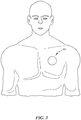
Fig. 3 is a view showing the PPG device applied to a patient; -
Fig. 4 is a set of bar graphs schematically illustrating the effect of the PPG device embodiments described herein on the signal received at the photodetectors; -
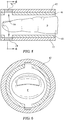
Figs. 5 and 6 are a cross sectional side elevation view and an end elevation view of an enveloping embodiment of the PPG device; -
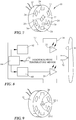
Figs. 7 and 8 are a schematic and a perspective view showing a PPG device having light emitting diodes, LED drivers, a photodetector, a temperature sensor, and a processor adapted to regulate drive current and/or operating time of one of the LED's; -
Fig. 9 is a view similar toFig. 7 showing a PPG device with three LED's, one of which is dedicated to warming the patient's skin; and -
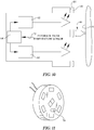
Figs. 10 and 11 are views similar to those ofFigs. 7 and 8 showing an embodiment which includes the mask of the embodiment ofFigs. 1, 2 ,5 and 6 and the temperature sensor and processor ofFigs. 7 and 8 . - The present invention may comprise one or more of the features recited in the appended claims and/or one or more of the following features or combinations thereof.
- In this specification and drawings, features similar to or the same as features already described may be identified by reference characters or numerals which are the same as or similar to those previously used. Similar elements may be identified by a common reference character or numeral, with suffixes being used to refer to specific occurrences of the element.
- Referring to
Fig. 1 , a photoplethysmography (PPG)device 10 includes anequipment module 12. Theequipment module 12 has a patient facing side orextremity 14 and an opposite side orextremity 16. When in use, thePPG device 10 is applied to the patient, for example by being secured to the patient, with thepatient facing extremity 14 facing the patient and theopposite extremity 16 facing away from the patient. InFig. 2 the patient is represented by a patch of skin S. - The
equipment module 12 includes a first light emitting diode (LED) 20 adapted to emit light of a first wavelength λ1 from thepatient facing extremity 14 of theequipment module 12. In one embodiment the first wavelength is from the visible portion of the electromagnetic spectrum, for example about 650 nm which corresponds to visible red light. Theequipment module 12 also includes a secondlight emitting diode 22 adapted to emit light of a second wavelength λ2 from thepatient facing extremity 14 of theequipment module 12. The second wavelength is from the infrared portion of the electromagnetic spectrum, for example about 950 nm. As is evident from the foregoing, the word "light," as used in this specification, is not limited to emissions in the visible portion of the electromagnetic spectrum. - The
PPG device 10 ofFig. 1 also includes a driver, not illustrated but similar todrivers - The
equipment module 12 also includes aphotodetector 24 such as a photodiode. Photodiodes are used as the example of the photodetector in the balance of this specification. The illustrated embodiment includes an array of sixphotodiodes 24 arranged in a ring that circumscribes the first and second LED's 20, 22. -
Wires 26 extend fromopposite side 16 of thePPG device 10 to connect thedevice 10 to an electrical power source and, if necessary, to provide an information or data communication pathway. In other embodiments thedevice 10 may be powered by an on-board battery and/or the communication may be by wireless communication. - The
PPG 10 device also includes amask 40 having amodule facing side 42 and apatient facing side 44. In one embodiment themask 40 includes an aluminum foil layer that reflects radiation back into the tissue. Such areflective mask 40 may reflect radiation across a broad spectrum of wavelengths or may be tailored to reflect radiation of only a selected wavelength band. In another embodiment, themask 40 is an insulating mask which is not necessarily reflective. -
Mask 40 includes acenter window 50 and a set of sixperipheral windows 52. As seen best inFig. 2 , themask 40 covers thepatient facing extremity 14 of theequipment module 12 so that when thePPG device 10 is applied to a patient, themask 40 is situated between the patient and thepatient facing extremity 14 of theequipment module 12. In addition,center window 50 registers with LED's 20, 22, and eachperipheral window 52 registers with a respective one of thephotodiodes 24. -
Window 50 is transparent to the wavelengths of light emitted by LED's 20, 22. Taking 650 nm and 950 nm as an example, in one embodiment, theentire center window 50 is transparent to at least 650 nm and 950 nm light. In another embodiment,center window 50 has a first segment which overliesfirst LED 20 and is transparent to 650 nm light, and a second segment which overliessecond LED 22 and is transparent to 950 nm light. Yet another embodiment includes two separate windows, one overlying the 650 nm first LED and transparent to 650 nm light, and the other overlying the 950 nm first LED and transparent to 950 nm light. Window orwindows 50 may be openings, or may be a material having the requisite transparency. - In order for the
photodiodes 24 to receive light reflected from the patient's tissue at both the first and second wavelengths,peripheral windows 52 are transparent to those wavelengths.Windows 52 may be openings, or may be a material having the requisite transparency. - In operation, the
device 10 is applied to the patient as seen best inFigs. 2 and3. Fig. 3 shows thePPG device 10 applied to the patient's chest, however it may be applied elsewhere. Continuing to use the example of 650 and 950 nm light, the light emissions from first and second LED's enter the patient's tissue (arrows E650, E950). Light reflected back from the patient's tissue, R650, R950, arrives at thephotodiodes 24 due to the transparency ofperipheral windows 52 to the 650 and 950 wavelengths. The tissue-reflected radiation that does not pass through windows 52 (or through window 50) is trapped in the tissue by themask 40. The trapped radiation, whether or not introduced by the 650 nm and 950 nm light sources, causes warming of the tissue above and beyond any warming that might occur if themask 40 were not present. The pulsating arterial blood flow increases in response to the warmth. The tissue other than the pulsating arterial blood (e.g. flesh, bone) is largely or entirely unaffected by the warmth. Referring additionally toFig. 4 , the information bearing AC portion of the "warm" signal received at thephotodetectors 24 is therefore amplified in comparison to the "cold" AC signal that would be obtained without the warming attributable to themask 40. The "warm" AC signal is therefore larger than the "cold" AC signal, both in absolute terms and in proportion to the DC component of the signal. As a result the "warm" AC signal is easier to detect, and its information content is easier to extract than is the case with the "cold" AC signal. - As seen in
Fig. 2 and3 , thePPG device 10, as applied to a patient, is non-enveloping. In other words, thedevice 10 does not envelope a portion of the patient's anatomy.Figs. 5 and 6 show an alternative in which the PPG device envelopes or partially envelops a patient's finger F. The space between the patient and the PPG device is exaggerated to preserve the clarity of the illustration. Because the LED's 20, 22 andphotodetector 24 are on opposite sides of the patient's finger, the device ofFigs. 5 and 6 is a transmittance PPG device. The principles already described nevertheless apply. That is,mask 40 onmodule 12 traps radiation in the patient's finger F causing the tissue warming and beneficial effect on the AC component of the signal received at thephotodetector 24 as already described. - A method for conducting a photoplethsymographic (PPG) procedure in accordance with the embodiments described above includes illuminating a tissue sample with radiation of a first wavelength and radiation of a second wavelength, and trapping radiation in the tissue sample. The method includes detecting at least a portion of tissue-reflected first wavelength radiation and tissue-reflected second wavelength radiation (i.e. the radiation that was not trapped in the tissue). The method also includes analyzing the detected first wavelength radiation and the detected second wavelength radiation to determine a parameter of interest. Such parameter of interest may include blood oxygen saturation, to name just one of many that will occur to those skilled in the art.
- Referring to
Figs. 7 and 8 aPPG device 10 includes afirst LED 20 adapted to emit light of a first wavelength λ1 (e.g. a visible wavelength such as 650 nm), asecond LED 22 adapted to emit light of a second wavelength λ2 (e.g. an infrared wavelength such as 950 nm) and aphotodetector 24. The foregoing description of these components in connection with thePPG device 10 shown inFigs. 1, 2 ,5 and 6 also applies to thedevice 10 ofFigs. 7 and 8 . ThePPG device 10 also includes first andsecond LED drivers processor 64. A patient is represented by a patch of skin S. The space between the patient and thePPG device 10 is exaggerated to preserve the clarity of the illustration. -
Processor 64 is adapted to control the drive current output fromsecond LED driver 62 and/or the operating time of thesecond LED 22 in order to achieve an elevated localized body tissue temperature of the patient to which thePPG device 10 is applied. Elevated temperature means a temperature higher than that which would result if the drive current and/or LED operating time were not controlled in a way intended to achieve a tissue temperature high enough to boost the AC portion of the signal received at thephotodetector 24 as seen inFig. 4 . For example theprocessor 64 may cause thedriver 62 to supply more drive current to thesecond LED 22 than would be the case if the thermal effect on the tissue and the accompanying beneficial effect on the AC portion of the signal (FIG. 4 ) were not sought. Or, theprocessor 64 may cause thesecond LED 22 to illuminate the tissue for longer time intervals than would be necessary if the thermal effect on the tissue and the accompanying beneficial effect on the AC portion of the signal (FIG. 4 ) were not sought. Or, theprocessor 64 may command a combination of increased drive current and increased LED operating time. - The PPG may also include a temperature sensor adapted to detect the body tissue temperature. In
Figs. 7 and 8 the temperature sensor is illustrated as athermocouple 70.Feedback 72 from thetemperature sensor 70 is used to control drive current and/or operating time of thesecond LED 22 to achieve and maintain the detected body tissue temperature at a specified value. One temperature believed to be satisfactory is about 40° C. -
Fig. 9 shows an embodiment of the PPG device ofFigs. 7 and 8 having afirst LED 20 adapted to emit light of a first wavelength λ1 (e.g. a visible wavelength such as 650 nm). The PPG device also includes an array of one or more second LED's 22-1, 22-2 all adapted to emit light of a second wavelength λ2 (e.g. an infrared wavelength such as 950 nm). The second LED's 22-1, 22-2 provide illumination at a second (e.g. infrared) wavelength, just as in a conventional PPG device. The second LED's 22-1, 22-2 also help to achieve the elevated body tissue temperature. In one embodiment, several second LED's are provided in order to achieve the desired tissue warming effect and the attendant beneficial effect on the AC portion of the signal as shown inFig. 4 . In addition, the embodiment ofFig. 9 may include the temperature sensor ofFigs. 7 and 8 for the purposes already described. - A method for conducting a photoplethsymographic (PPG) procedure in accordance with the embodiments described above includes warming a tissue sample with radiation of a second wavelength and illuminating the tissue sample with radiation of a first wavelength and radiation of the second wavelength. The method also includes detecting tissue-reflected first wavelength radiation and tissue-reflected second wavelength radiation. The method also includes analyzing the detected first wavelength radiation and the detected second wavelength radiation to determine a parameter of interest.
-
Figs. 10 and 11 show a PPG device which includes both amask 40 as inFigs. 1, 2 ,5 and 6 , and aprocessor 64 adapted to control drive current and operating time of the second LED to achieve an elevated localized body tissue temperature of a patient to which the PPG device is applied as inFigs. 7 and 9 . The embodiment ofFigs. 10 and 11 combines the features and operational benefits of the embodiments ofFigs. 1, 2 ,5 and 6 with the features and operational benefits of the embodiment ofFigs. 7 and 9 . - A method for conducting a photoplethsymographic (PPG) procedure in accordance with the combined embodiments described above includes warming a tissue sample with radiation of a second wavelength and trapping heat energy in the tissue sample. The method also includes illuminating the tissue sample with radiation of a first wavelength and radiation of the second wavelength. The method also includes detecting at least a portion of tissue-reflected first wavelength radiation and at least a portion of tissue-reflected second wavelength radiation (i.e. the tissue reflected first and second wavelength radiation that was not trapped in the tissue). The method also includes analyzing the detected first wavelength radiation and the detected second wavelength radiation to determine a parameter of interest.
- Although this disclosure refers to specific embodiments, it will be understood by those skilled in the art that various changes in form and detail may be made.
- Embodiments of the invention can be described with reference to the following numbered clauses, with preferred features laid out in the dependent clauses:
- 1. A photoplethysmography (PPG) device comprising:
- an equipment module which includes:
- a first light emitting diode (LED) adapted to emit light of a first wavelength from a patient facing extremity of the equipment module;
- a second LED adapted to emit light of a second wavelength from the patient facing extremity of the equipment module; and
- a photodetector; and
- a mask covering the patient facing extremity of the equipment module so that when the PPG device is applied to a patient the mask is situated between the patient and the patient facing extremity.
- an equipment module which includes:
- 2. The PPG device of clause 1, wherein the mask comprises a reflective mask.
- 3. The PPG device of either clause 1 or clause 2, wherein the PPG device is non-enveloping when applied to the patient.
- 4. The PPG device of any preceding clause, wherein the photodetector comprises a photodiode.
- 5. The PPG device of any preceding clause, wherein the photodetector comprises an array of two or more photodetectors.
- 6. The PPG device of clause 5, wherein the photodetector comprises a ring of photodetectors circumscribing the first and second LED's.
- 7. The PPG device of any preceding clause, further comprising a processor adapted to control a drive current and an operating time of the second LED to achieve an elevated body tissue temperature of a patient to which the PPG device is applied.
- 8. The PPG device of clause 7, further comprising a temperature sensor adapted to detect the elevated body tissue temperature.
- 9. The PPG device of clause 8, wherein the processor is adapted to control the drive current and the operating time of the second LED to achieve and maintain the detected elevated body tissue temperature at a specified value.
- 10. The PPG device of any preceding clause, wherein the first wavelength is from a visible portion of an electromagnetic spectrum and the second wavelength is from an infrared portion of the electromagnetic spectrum.
- 11. A photoplethysmography (PPG) device comprising:
- a first light emitting diode (LED) adapted to emit light of a first wavelength;
- a second LED adapted to emit light of a second wavelength;
- a photodetector; and
- a processor adapted to control a drive current and/or an operating time of the second LED to achieve an elevated localized body tissue temperature of a patient to which the PPG device is applied.
- 12. The PPG device of clause 11, further comprising a temperature sensor adapted to detect the elevated localized body tissue temperature.
- 13. The PPG device of
clause 12, wherein the processor is adapted to control the drive current and/or the operating time of the second LED to achieve and maintain the elevated localized body tissue temperature at a specified value. - 14. The PPG device of any one of clauses 11 to 13, wherein the first wavelength is from a visible portion of an electromagnetic spectrum and the second wavelength is from an infrared portion of the electromagnetic spectrum.
- 15. A method for conducting a photoplethsymographic (PPG) procedure, the method comprising:
- illuminating a tissue sample with radiation of a first wavelength and radiation of a second wavelength;
- trapping radiation in the tissue sample;
- detecting at least a portion of tissue-reflected first wavelength radiation and tissue-reflected second wavelength radiation; and
- analyzing the tissue-reflected first wavelength radiation and a detected non-reintroduced second wavelength radiation to determine a parameter of interest.
- 16. The method of clause 15, further comprising warming the tissue sample with radiation of the second wavelength prior to detecting the at least a portion of tissue-reflected first wavelength radiation and the tissue-reflected second wavelength radiation.
- 17. The method of either clause 15 or
clause 16, further comprising warming the tissue sample with radiation of the second wavelength prior to illuminating the tissue sample with radiation of the first wavelength and radiation of the second wavelength. - 18. A method for conducting a photoplethsymographic (PPG) procedure, the method comprising:
- warming a tissue sample with radiation of a second wavelength;
- illuminating the tissue sample with radiation of a first wavelength and radiation of the second wavelength;
- detecting tissue-reflected first wavelength radiation and tissue-reflected second wavelength radiation; and
- analyzing the tissue-reflected first wavelength radiation and the tissue-reflected second wavelength radiation to determine a parameter of interest.
Claims (13)
- A photoplethysmography (PPG) device comprising:an equipment module which includes:a first light emitting diode (LED) adapted to emit light of a first wavelength from a patient facing extremity of the equipment module;a second LED adapted to emit light of a second wavelength from the patient facing extremity of the equipment module; anda photodetector; anda mask covering the patient facing extremity of the equipment module so that when the PPG device is applied to a patient the mask is situated between the patient and the patient facing extremity.
- The PPG device of claim 1, wherein the mask comprises a reflective mask.
- The PPG device of either claim 1 or claim 2, wherein the PPG device is non-enveloping when applied to the patient.
- The PPG device of any preceding claim, wherein the photodetector comprises a photodiode.
- The PPG device of any preceding claim, wherein the photodetector comprises an array of two or more photodetectors.
- The PPG device of claim 5, wherein the photodetector comprises a ring of photodetectors circumscribing the first and second LED's.
- The PPG device of any preceding claim, further comprising a processor adapted to control a drive current and an operating time of the second LED to achieve an elevated body tissue temperature of a patient to which the PPG device is applied.
- The PPG device of claim 7, further comprising a temperature sensor adapted to detect the elevated body tissue temperature.
- The PPG device of claim 8, wherein the processor is adapted to control the drive current and the operating time of the second LED to achieve and maintain the detected elevated body tissue temperature at a specified value.
- The PPG device of any preceding claim, wherein the first wavelength is from a visible portion of an electromagnetic spectrum and the second wavelength is from an
- A method for conducting a photoplethsymographic (PPG) procedure, the method comprising:illuminating a tissue sample with radiation of a first wavelength and radiation of a second wavelength;trapping radiation in the tissue sample;detecting at least a portion of tissue-reflected first wavelength radiation and tissue-reflected second wavelength radiation; andanalyzing the tissue-reflected first wavelength radiation and a detected non-reintroduced second wavelength radiation to determine a parameter of interest.
- The method of claim 11, further comprising warming the tissue sample with radiation of the second wavelength prior to detecting the at least a portion of tissue-reflected first wavelength radiation and the tissue-reflected second wavelength radiation.
- The method of either claim 11 or claim 12, further comprising warming the tissue sample with radiation of the second wavelength prior to illuminating the tissue sample with radiation of the first wavelength and radiation of the second wavelength.
Applications Claiming Priority (2)
| Application Number | Priority Date | Filing Date | Title |
|---|---|---|---|
| US201962854502P | 2019-05-30 | 2019-05-30 | |
| US201962860862P | 2019-06-13 | 2019-06-13 |
Publications (1)
| Publication Number | Publication Date |
|---|---|
| EP3744251A1 true EP3744251A1 (en) | 2020-12-02 |
Family
ID=70804521
Family Applications (1)
| Application Number | Title | Priority Date | Filing Date |
|---|---|---|---|
| EP20176061.8A Pending EP3744251A1 (en) | 2019-05-30 | 2020-05-22 | Photoplethysmograph device with thermal trapping and/or warming capability and related methods |
Country Status (2)
| Country | Link |
|---|---|
| US (1) | US11607146B2 (en) |
| EP (1) | EP3744251A1 (en) |
Families Citing this family (1)
| Publication number | Priority date | Publication date | Assignee | Title |
|---|---|---|---|---|
| KR20220045341A (en) * | 2020-10-05 | 2022-04-12 | 삼성전자주식회사 | Apparatus and method for estimating bio-information |
Citations (1)
| Publication number | Priority date | Publication date | Assignee | Title |
|---|---|---|---|---|
| US5158082A (en) * | 1990-08-23 | 1992-10-27 | Spacelabs, Inc. | Apparatus for heating tissue with a photoplethysmograph sensor |
Family Cites Families (24)
| Publication number | Priority date | Publication date | Assignee | Title |
|---|---|---|---|---|
| US4259963A (en) | 1979-07-03 | 1981-04-07 | Albert Huch | Multi-purpose transducer for transcutaneous blood measurements |
| US4723554A (en) | 1984-04-27 | 1988-02-09 | Massachusetts Institute Of Technology | Skin pallor and blush monitor |
| JPS6323645A (en) * | 1986-05-27 | 1988-01-30 | 住友電気工業株式会社 | Reflection heating type oxymeter |
| US4714080A (en) | 1986-10-06 | 1987-12-22 | Nippon Colin Co., Ltd. | Method and apparatus for noninvasive monitoring of arterial blood oxygen saturation |
| US5007423A (en) | 1989-10-04 | 1991-04-16 | Nippon Colin Company Ltd. | Oximeter sensor temperature control |
| US5560652A (en) | 1994-06-21 | 1996-10-01 | Zoland; Martin | Note pad with single hole or pair of slits and writing instrument combination |
| US5766127A (en) | 1996-04-15 | 1998-06-16 | Ohmeda Inc. | Method and apparatus for improved photoplethysmographic perfusion-index monitoring |
| US20070185393A1 (en) | 2006-02-03 | 2007-08-09 | Triage Wireless, Inc. | System for measuring vital signs using an optical module featuring a green light source |
| EP2292141B1 (en) | 2009-09-03 | 2015-06-17 | The Swatch Group Research and Development Ltd | Method and device for taking a patient's pulse using light waves with two wavelengths |
| WO2011077294A1 (en) | 2009-12-21 | 2011-06-30 | Koninklijke Philips Electronics N.V. | Method of and apparatus for processing photoplethymograph signals |
| US9526431B2 (en) | 2011-10-19 | 2016-12-27 | Biovotion Ag | System for noninvasive optical measurements of physiological properties in tissue |
| US9138181B2 (en) * | 2011-12-16 | 2015-09-22 | Covidien Lp | Medical sensor for use with headband |
| WO2014003806A1 (en) | 2012-06-29 | 2014-01-03 | Xhale, Inc. | Photoplethysmography sensors |
| US10610159B2 (en) | 2012-10-07 | 2020-04-07 | Rhythm Diagnostic Systems, Inc. | Health monitoring systems and methods |
| US20140275890A1 (en) | 2013-03-15 | 2014-09-18 | Covidien Lp | Systems and methods for sensor calibration in photoplethsymography |
| CN112869727B (en) | 2013-03-16 | 2024-03-19 | 恩帕蒂卡有限责任公司 | Device for measurement of electrodermal activity using current compensation |
| US10149628B2 (en) | 2014-05-20 | 2018-12-11 | Samsung Electronics Co., Ltd. | Signal processing method and apparatus |
| PL3016582T3 (en) | 2014-06-30 | 2017-09-29 | Koninklijke Philips N.V. | Photoplethysmography sensor apparatus and method |
| TWI530276B (en) | 2014-07-08 | 2016-04-21 | 原相科技股份有限公司 | Biometric detection module with denoising function and biometric detection method thereof |
| KR102455629B1 (en) | 2014-12-29 | 2022-10-17 | 삼성전자주식회사 | Apparatus and method for processing bio-signal |
| US10687742B2 (en) | 2015-06-12 | 2020-06-23 | ChroniSense Medical Ltd. | Using invariant factors for pulse oximetry |
| US10973422B2 (en) | 2016-01-22 | 2021-04-13 | Fitbit, Inc. | Photoplethysmography-based pulse wave analysis using a wearable device |
| US10219711B2 (en) | 2016-07-29 | 2019-03-05 | Fitbit, Inc. | Circuits and methods for photoplethysmographic sensors |
| KR102599772B1 (en) * | 2018-06-19 | 2023-11-08 | 삼성전자주식회사 | Biometric information sensing device and controlling method thereof |
-
2020
- 2020-05-15 US US16/875,383 patent/US11607146B2/en active Active
- 2020-05-22 EP EP20176061.8A patent/EP3744251A1/en active Pending
Patent Citations (1)
| Publication number | Priority date | Publication date | Assignee | Title |
|---|---|---|---|---|
| US5158082A (en) * | 1990-08-23 | 1992-10-27 | Spacelabs, Inc. | Apparatus for heating tissue with a photoplethysmograph sensor |
Non-Patent Citations (1)
| Title |
|---|
| MENDELSON Y ET AL: "SKIN REFLECTANCE OXIMETRY: IN VIVO MEASUREMENTS FROM THE FOREARM AND CALF", JOURNAL OF CLINICAL MONITORING, BOSTON, MA, US, vol. 7, 1 January 1991 (1991-01-01), pages 7 - 12, XP001040736, DOI: 10.1007/BF01617892 * |
Also Published As
| Publication number | Publication date |
|---|---|
| US11607146B2 (en) | 2023-03-21 |
| US20200375478A1 (en) | 2020-12-03 |
Similar Documents
| Publication | Publication Date | Title |
|---|---|---|
| US11864922B2 (en) | Low-noise sensor system | |
| US8401602B2 (en) | Secondary-emitter sensor position indicator | |
| RU2664600C2 (en) | Marker with light-emitting area for use in determining information on vital signs | |
| EP3273850B1 (en) | Optical vital signs sensor | |
| US7027849B2 (en) | Blood parameter measurement system | |
| US10660524B2 (en) | System and method for determining vital sign information of a subject | |
| CN102641126B (en) | For the sensor of the blood characteristics of non-intruding monitor person under inspection, equipment and method | |
| EP0247777A1 (en) | A sensor head and an oximeter including it | |
| US8708900B2 (en) | LED drive circuit and method for using same | |
| KR20090027200A (en) | Skin monitoring device, method of monitoring the skin, monitoring device, method of irradiating the skin, and use of an oled | |
| US12070333B2 (en) | Wearable device for sensing vital signs | |
| US11607146B2 (en) | Photoplethysmography device with thermal trapping and/or warming capability and associated methods | |
| RU2696422C2 (en) | Optical analysis system and method | |
| Natarasan et al. | Design and Implementation of Heartbeat rate and SpO2 Detector by using IoT for patients | |
| CN117813048A (en) | Determine the oxygenation level of one or more cells | |
| EP3539472B1 (en) | Compact, energy efficient physiological parameter sensor system | |
| CN121729266A (en) | Determining oxygenation level of one or more cells | |
| US20210393149A1 (en) | Methods for determining blood oxygenation and tissue perfusion levels and devices thereof | |
| KR101785831B1 (en) | Biological Signal Detecting System | |
| US20260114763A1 (en) | Determining Blood-Oxygen Level (SpO2) Using Broadband Spectra To Reduce Or Eliminate Skin-Tone Bias In The Determined SpO2 Value, And/Or Using Broadband Spectra to Determine Pulse Rate | |
| JP2019130070A (en) | Biological information measurement device | |
| Stojanovic et al. | Led-Led PPG-SpO2 Sensor-Actuator |
Legal Events
| Date | Code | Title | Description |
|---|---|---|---|
| PUAI | Public reference made under article 153(3) epc to a published international application that has entered the european phase |
Free format text: ORIGINAL CODE: 0009012 |
|
| STAA | Information on the status of an ep patent application or granted ep patent |
Free format text: STATUS: THE APPLICATION HAS BEEN PUBLISHED |
|
| AK | Designated contracting states |
Kind code of ref document: A1 Designated state(s): AL AT BE BG CH CY CZ DE DK EE ES FI FR GB GR HR HU IE IS IT LI LT LU LV MC MK MT NL NO PL PT RO RS SE SI SK SM TR |
|
| AX | Request for extension of the european patent |
Extension state: BA ME |
|
| STAA | Information on the status of an ep patent application or granted ep patent |
Free format text: STATUS: REQUEST FOR EXAMINATION WAS MADE |
|
| 17P | Request for examination filed |
Effective date: 20210528 |
|
| RBV | Designated contracting states (corrected) |
Designated state(s): AL AT BE BG CH CY CZ DE DK EE ES FI FR GB GR HR HU IE IS IT LI LT LU LV MC MK MT NL NO PL PT RO RS SE SI SK SM TR |
|
| STAA | Information on the status of an ep patent application or granted ep patent |
Free format text: STATUS: EXAMINATION IS IN PROGRESS |
|
| 17Q | First examination report despatched |
Effective date: 20230705 |