EP3744212A1 - Fire-based cutting tool and use thereof - Google Patents
Fire-based cutting tool and use thereof Download PDFInfo
- Publication number
- EP3744212A1 EP3744212A1 EP19743132.3A EP19743132A EP3744212A1 EP 3744212 A1 EP3744212 A1 EP 3744212A1 EP 19743132 A EP19743132 A EP 19743132A EP 3744212 A1 EP3744212 A1 EP 3744212A1
- Authority
- EP
- European Patent Office
- Prior art keywords
- tool
- arm
- burner
- arms
- gripping parts
- Prior art date
- Legal status (The legal status is an assumption and is not a legal conclusion. Google has not performed a legal analysis and makes no representation as to the accuracy of the status listed.)
- Granted
Links
Images

Classifications
-
- A—HUMAN NECESSITIES
- A45—HAND OR TRAVELLING ARTICLES
- A45D—HAIRDRESSING OR SHAVING EQUIPMENT; EQUIPMENT FOR COSMETICS OR COSMETIC TREATMENTS, e.g. FOR MANICURING OR PEDICURING
- A45D26/00—Hair-singeing apparatus; Apparatus for removing superfluous hair, e.g. tweezers
-
- A—HUMAN NECESSITIES
- A45—HAND OR TRAVELLING ARTICLES
- A45D—HAIRDRESSING OR SHAVING EQUIPMENT; EQUIPMENT FOR COSMETICS OR COSMETIC TREATMENTS, e.g. FOR MANICURING OR PEDICURING
- A45D44/00—Other cosmetic or toiletry articles, e.g. for hairdressers' rooms
- A45D44/02—Furniture or other equipment specially adapted for hairdressers' rooms and not covered elsewhere
-
- A—HUMAN NECESSITIES
- A45—HAND OR TRAVELLING ARTICLES
- A45D—HAIRDRESSING OR SHAVING EQUIPMENT; EQUIPMENT FOR COSMETICS OR COSMETIC TREATMENTS, e.g. FOR MANICURING OR PEDICURING
- A45D1/00—Curling-tongs, i.e. tongs for use when hot; Curling-irons, i.e. irons for use when hot; Accessories therefor
- A45D1/02—Curling-tongs, i.e. tongs for use when hot; Curling-irons, i.e. irons for use when hot; Accessories therefor with means for internal heating, e.g. by liquid fuel
-
- A—HUMAN NECESSITIES
- A45—HAND OR TRAVELLING ARTICLES
- A45D—HAIRDRESSING OR SHAVING EQUIPMENT; EQUIPMENT FOR COSMETICS OR COSMETIC TREATMENTS, e.g. FOR MANICURING OR PEDICURING
- A45D24/00—Hair combs for care of the hair; Accessories therefor
- A45D24/36—Combs, stencils, or guides, specially adapted for hair trimming devices
-
- B—PERFORMING OPERATIONS; TRANSPORTING
- B26—HAND CUTTING TOOLS; CUTTING; SEVERING
- B26B—HAND-HELD CUTTING TOOLS NOT OTHERWISE PROVIDED FOR
- B26B13/00—Hand shears; Scissors
- B26B13/22—Hand shears; Scissors combined with auxiliary implements, e.g. with cigar cutter, with manicure instrument
- B26B13/24—Hand shears; Scissors combined with auxiliary implements, e.g. with cigar cutter, with manicure instrument to aid hair cutting
Definitions
- the present invention relates to a fire-based cutting tool which uses fire and is particularly useful in hairdressing salons. This also relates to its operating procedure.
- One of the current hairdressing techniques is to singe the ends of the hair with a flame.
- candles and other such flames are used.
- the flame is always on, which increases safety risks, and the cut itself has to be done with scissors or another tool.
- WO2005117640 is a well-known body hair-removing method which uses a burner flame.
- the invention consists of a hairdressing tool that cuts with a flame. This tool, with its different applications, resolves the background of the invention's previous problems. This document also relates to its operating procedure.
- the 'rotation plane of the shaft' is defined as the perpendicular plane to said shaft that passes through its midpoint.
- the fire-based cutting tool is comprised of a pair of tongs formed by two long arms joined by a shaft. Each arm has a handle and a gripping part for the object held by the tongs.
- the first arm has a burner with a nozzle on one side of the rotating shaft, facing the contact zone of the gripping parts. The nozzle is parallel to the arms so that the flame produced does not intersect with them but is kept close to the rotating shaft (and the gripping parts).
- the burner also consists of an activation button, which is attached to the handle of the first arm, preferably including safety measures such as those cited later on in the document.
- the tongs shall be of a type where the handles are placed between the shaft and the gripping parts, although it may be of a 'scissor' type.
- the burner comprises a fuel tank that would normally be contained in the first arm.
- the burner prefferably produces a flame that is at least 5cm in length.
- the fuel tank pressure and the design of the nozzle will be combined.
- the gripping parts each have a safety guard that prevent the flame from being projected sideways.
- These safety guards increase in thickness (along the rotating shaft), which prevents heat from reaching the customer.
- One of the guards can be made into a comb by creating a set of narrow teeth.
- a second measure, compatible with the first, is an activator on the button or on the burner, attached to the first arm, in the interior, and oriented towards the second arm. In this way, the burner can only be activated when the tongs are closed.
- the cutting tool shown in figure 1 corresponds to a pair of tongs (1) that have two long arms (2, 2') joined by a common shaft (3).
- Each arm (2, 2') can be divided into a hair gripping part and a handle (5).
- the handle (5) will be between the shaft (3) and the gripping part (4) or on the opposite end of the gripping part (4). In general, for ergonomic purposes, it is better for the handle (5) to be between the shaft (3) and the gripping part (4) ( figure 1 ).
- the arms (2, 2') are not identical, but rather the handle (5) of one of them (called the "first arm (2)") has a burner (6) with a fuel tank (7), a nozzle (8) and a button (9).
- the burner (6) can also have an inlet to refill the tank (7) and/or be detachable from the handle (5) for refilling or for replacement.
- a more complicated solution would be to have an external tank (7) connected to the nozzle (8) through a tube. However, this is less preferable given that it is not as safe.
- the nozzle (8) of the burner (6) is attached to one side of the arm (2), so that when the tongs (1) are closed and are clasping an object, the nozzle (8) points towards one of the halves of the object. So, turning on the burner (6) with the button (9) results in the burning of this part of the object.
- the tank (7) It is important for the tank (7) to maintain enough pressure, so the flame from the nozzle (8) can be kept under control. This means that the flame will not be affected by draughts of air and is always straight. The cut will therefore be uniform and will be able to reach a relatively large area (from 4-5 to 10-15cm in length for cutting hair, or a shorter length for other uses). Thus, the hair can be laid flat, along the entire length of the gripping parts (4) and the cut is easier and more uniform.
- the design of the nozzle (8) can also help adjust the flame in order to correctly cover the area to be cut.
- One such example of a nozzle (8) would be that of a propane torch used to remove paint or that used as a pipe lighter or a blowtorch.
- nozzle (8) and reservoir (7) are well known and so do not require any further explanation.
- the nozzle (8) would preferably have a piezoelectric activation and have three or more outlets, in order to ensure that it lights properly and that the flame is maintained.
- the gripping part (4) of the arms (2, 2') form a guard (10); for example, by making them very thick (more than 1.5cm, preferably 2cm) on the rotating shaft (3).
- a protective barrier is created from the rest of the hair.
- the thickness will be great enough to form a guard (10) or barrier, whilst on the other arm thickness will also be great enough to provide protection but consists of teeth to make a comb (11).
- the guard (10) can be flat or curved to adapt to the position of the hand and/or to collect the ash. It can also be continuous or be made narrower as it moves away from the nozzle ( figure 3 ).
- the user can use the comb (11) of the tongs (1) to section off a piece of hair that they wish to cut, pick it up with the other hand and clasp it with the tongs (1) in order to free the hand. Then, the burner (6) is lit to cut and cauterise the hair in one single action.
- the clamping arms (2, 2') can be designed in various shapes and sizes according to different needs and can even be interchangeable so that the tool can better adapt to the needs of the user. In other words, it can be dismantled in order to change or remove the type of guard (10), comb (11) ... It is better for the second arm (2') to be the one that completely or partly detaches.
- the button (9) will ideally have some type of safety measure to prevent it from accidentally being turned on. This can either be a cap, or a safety catch (not shown) that prevents it from clamping if it is not removed by hand against a spring, or an activator (12) on the first arm (2) facing the second arm (2'). This activator (12) will be near the gripping parts (4) of the arms (2, 2'), so that the burner (6) cannot activate itself if the gripping parts (4) are not close together.
- the handles (5) should consist of thermal protection for the burner (6) and for the user's hands. It is also of interest to cover the side of the tongs (1) opposite the burner (6) with thermal protection, like an insulating paint, for example. As such, even if the burner (6) is used too often, the side pointing towards the client will not be as hot as the opposite one. In any case, as the flame is parallel to the arms (2, 2') and has a large surface area to dispel heat, the temperature will never be too excessive.
- the first option comprises of two silicone strips (13) or any other soft, heat-resistant material. These strips (13) would be placed on the gripping parts (4) of the tongs (1), to ensure that the hair is firmly kept in place. This would be placed on the edge of the arms (2, 2') so that part of it will protect them from the flame.
- the second addition is a tail comb (14) on the free guard (10) without the comb (11), so as to allow the user to better section off the client's hair, marking the parting.
- centring piece (15, 15') placed at the end of the gripping parts (4), that comprises a wedge-shaped protrusion (15) on one arm (2, 2') and a complementary slot (15') on the other.
- This centring piece (15, 15') ensures that the arms (2, 2') stay perfectly aligned when the tongs (1) are closed. In this manner, the burner (6) can be entirely parallel to both.
- Other examples of centring pieces (15, 15') are: cone-shaped protrusions with their complementary slots, two symmetrical and divergent wedge-shapes on an arm (2, 2') that clasp the other one ...
Landscapes
- Gripping Jigs, Holding Jigs, And Positioning Jigs (AREA)
- Scissors And Nippers (AREA)
Abstract
Description
- The present invention relates to a fire-based cutting tool which uses fire and is particularly useful in hairdressing salons. This also relates to its operating procedure.
- One of the current hairdressing techniques is to singe the ends of the hair with a flame. For this, candles and other such flames are used. Thus, the flame is always on, which increases safety risks, and the cut itself has to be done with scissors or another tool.
- In addition,
WO2005117640 is a well-known body hair-removing method which uses a burner flame. - The applicant does not know of any other tool that could be considered similar to this invention.
- The invention consists of a hairdressing tool that cuts with a flame. This tool, with its different applications, resolves the background of the invention's previous problems. This document also relates to its operating procedure.
- Prior to describing the invention, firstly, the 'rotation plane of the shaft' is defined as the perpendicular plane to said shaft that passes through its midpoint.
- The fire-based cutting tool is comprised of a pair of tongs formed by two long arms joined by a shaft. Each arm has a handle and a gripping part for the object held by the tongs. The first arm has a burner with a nozzle on one side of the rotating shaft, facing the contact zone of the gripping parts. The nozzle is parallel to the arms so that the flame produced does not intersect with them but is kept close to the rotating shaft (and the gripping parts). The burner also consists of an activation button, which is attached to the handle of the first arm, preferably including safety measures such as those cited later on in the document.
- Preferably, the tongs shall be of a type where the handles are placed between the shaft and the gripping parts, although it may be of a 'scissor' type.
- The burner comprises a fuel tank that would normally be contained in the first arm.
- It would be desirable for the burner to produce a flame that is at least 5cm in length. For this, the fuel tank pressure and the design of the nozzle will be combined.
- As a safety measure for the user and for the person receiving the haircut, the gripping parts each have a safety guard that prevent the flame from being projected sideways. These safety guards increase in thickness (along the rotating shaft), which prevents heat from reaching the customer. One of the guards can be made into a comb by creating a set of narrow teeth.
- As a safety measure, it is recommended to include a cap, or a removable spring safety catch on the button, in such a way that the user cannot accidentally press the button at the wrong time. It also works as a "deadman" system to ensure that the flame cuts out if the device is dropped.
- A second measure, compatible with the first, is an activator on the button or on the burner, attached to the first arm, in the interior, and oriented towards the second arm. In this way, the burner can only be activated when the tongs are closed.
- The intended use of this tool is for cutting hair.
- To better understand the invention, the following figures have been included.
-
Figure 1 : schematic view of a first example of production of the invention from a perpendicular angle to the rotating shaft. -
Figure 2 : schematic view of a second example of production, with a scissor type gripper. -
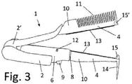
Figure 3 : details of a third example of production, more complete. - The following is a brief description of methods for creating the invention, as an illustrative example but it is not limited to this.
- The cutting tool shown in
figure 1 corresponds to a pair of tongs (1) that have two long arms (2, 2') joined by a common shaft (3). Each arm (2, 2') can be divided into a hair gripping part and a handle (5). Depending on the type of tongs (1), the handle (5) will be between the shaft (3) and the gripping part (4) or on the opposite end of the gripping part (4). In general, for ergonomic purposes, it is better for the handle (5) to be between the shaft (3) and the gripping part (4) (figure 1 ). - As it can be seen, the arms (2, 2') are not identical, but rather the handle (5) of one of them (called the "first arm (2)") has a burner (6) with a fuel tank (7), a nozzle (8) and a button (9). The burner (6) can also have an inlet to refill the tank (7) and/or be detachable from the handle (5) for refilling or for replacement. A more complicated solution would be to have an external tank (7) connected to the nozzle (8) through a tube. However, this is less preferable given that it is not as safe.
- The nozzle (8) of the burner (6) is attached to one side of the arm (2), so that when the tongs (1) are closed and are clasping an object, the nozzle (8) points towards one of the halves of the object. So, turning on the burner (6) with the button (9) results in the burning of this part of the object.
- It is important for the tank (7) to maintain enough pressure, so the flame from the nozzle (8) can be kept under control. This means that the flame will not be affected by draughts of air and is always straight. The cut will therefore be uniform and will be able to reach a relatively large area (from 4-5 to 10-15cm in length for cutting hair, or a shorter length for other uses). Thus, the hair can be laid flat, along the entire length of the gripping parts (4) and the cut is easier and more uniform. The design of the nozzle (8) can also help adjust the flame in order to correctly cover the area to be cut. One such example of a nozzle (8) would be that of a propane torch used to remove paint or that used as a pipe lighter or a blowtorch. However, this type of nozzle (8) and reservoir (7) are well known and so do not require any further explanation. The nozzle (8) would preferably have a piezoelectric activation and have three or more outlets, in order to ensure that it lights properly and that the flame is maintained.
- It is recommended that the gripping part (4) of the arms (2, 2') form a guard (10); for example, by making them very thick (more than 1.5cm, preferably 2cm) on the rotating shaft (3). Thus, a protective barrier is created from the rest of the hair. Preferably, on one arm (2, 2') the thickness will be great enough to form a guard (10) or barrier, whilst on the other arm thickness will also be great enough to provide protection but consists of teeth to make a comb (11). The guard (10) can be flat or curved to adapt to the position of the hand and/or to collect the ash. It can also be continuous or be made narrower as it moves away from the nozzle (
figure 3 ). - In this manner, the user can use the comb (11) of the tongs (1) to section off a piece of hair that they wish to cut, pick it up with the other hand and clasp it with the tongs (1) in order to free the hand. Then, the burner (6) is lit to cut and cauterise the hair in one single action.
- The clamping arms (2, 2') can be designed in various shapes and sizes according to different needs and can even be interchangeable so that the tool can better adapt to the needs of the user. In other words, it can be dismantled in order to change or remove the type of guard (10), comb (11) ... It is better for the second arm (2') to be the one that completely or partly detaches.
- The button (9) will ideally have some type of safety measure to prevent it from accidentally being turned on. This can either be a cap, or a safety catch (not shown) that prevents it from clamping if it is not removed by hand against a spring, or an activator (12) on the first arm (2) facing the second arm (2'). This activator (12) will be near the gripping parts (4) of the arms (2, 2'), so that the burner (6) cannot activate itself if the gripping parts (4) are not close together.
- All the materials used must be resistant to high temperatures, especially the gripping parts (4). In turn, the handles (5) should consist of thermal protection for the burner (6) and for the user's hands. It is also of interest to cover the side of the tongs (1) opposite the burner (6) with thermal protection, like an insulating paint, for example. As such, even if the burner (6) is used too often, the side pointing towards the client will not be as hot as the opposite one. In any case, as the flame is parallel to the arms (2, 2') and has a large surface area to dispel heat, the temperature will never be too excessive.
- In
figure 3 , three additional options are offered to enhance the tongs (1). The first option comprises of two silicone strips (13) or any other soft, heat-resistant material. These strips (13) would be placed on the gripping parts (4) of the tongs (1), to ensure that the hair is firmly kept in place. This would be placed on the edge of the arms (2, 2') so that part of it will protect them from the flame. - The second addition is a tail comb (14) on the free guard (10) without the comb (11), so as to allow the user to better section off the client's hair, marking the parting.
- Finally, the third addition is a centring piece (15, 15'), placed at the end of the gripping parts (4), that comprises a wedge-shaped protrusion (15) on one arm (2, 2') and a complementary slot (15') on the other. This centring piece (15, 15') ensures that the arms (2, 2') stay perfectly aligned when the tongs (1) are closed. In this manner, the burner (6) can be entirely parallel to both. Other examples of centring pieces (15, 15') are: cone-shaped protrusions with their complementary slots, two symmetrical and divergent wedge-shapes on an arm (2, 2') that clasp the other one ...
Claims (14)
- Fire-based cutting tool, characterised in that it consists of a pair of tongs (1) formed of two long arms (2, 2') joined by a shaft (3) each with handles (5) and each with gripping parts (4) for the object held by the tongs (1), where the first arm (2) comes with a burner (6) producing a controlled flame, with a nozzle (8) placed on one side of the rotating shaft (3) facing the contact zone of the gripping parts (4) and parallel to the arms (2, 2') and It also comprises an activation button (9) on the side of the handle (5) of the first blade (2).
- Tool, according to claim 1, wherein the handles (5) are placed between the shaft (3) and the gripping parts (4)
- Tool, according to claim 1, wherein the burner (6) comprises a fuel tank (7) in the first arm.
- Tool, according to claim 1, wherein the burner (6) produces a straight flame of at least 5 cm.
- Tool, according to claim 1, wherein the gripping parts (4) have safety guards (10) that prevent the flame or heat from passing through to the side.
- Tool, according to claim 5, wherein the guard (10) on at least one of the arms (2, 2') comprises teeth to make a comb (11).
- Tool, according to claim 1, which has a second detachable arm (2') opposite the first arm (2).
- Tool, according to claim 1, wherein the button (9) consists of a cap or a spring safety catch.
- Tool, according to claim 1, which comprises an activator (12) on the button (9) or on the burner (6) attached to the interior of the first arm (2) and facing the second arm (2').
- Tool, according to claim 1, which is covered in thermal protection on the side of the arms (2, 2') opposite the burner.
- Tool, according to claim 1, wherein the gripping parts (4) each comprise strips (13) of a soft, heat-resistant material.
- Tool, according to claim 6, which includes a tail comb (14) on the free end of the arm (2,2') opposite the comb (11).
- Tool, according to claim 1, which comprises of a centring piece (15, 15') on the two arms (2, 2') to ensure they are kept perfectly aligned.
- Use of fire-based cutting tool according to any of the claims from 1 to 13 to cut hair.
Applications Claiming Priority (2)
| Application Number | Priority Date | Filing Date | Title |
|---|---|---|---|
| ES201830066A ES2721123A1 (en) | 2018-01-25 | 2018-01-25 | FIRE CUTTING TOOL AND USE OF THE SAME |
| PCT/ES2019/070039 WO2019145590A1 (en) | 2018-01-25 | 2019-01-28 | Fire-based cutting tool and use thereof |
Publications (4)
| Publication Number | Publication Date |
|---|---|
| EP3744212A1 true EP3744212A1 (en) | 2020-12-02 |
| EP3744212A4 EP3744212A4 (en) | 2021-11-17 |
| EP3744212B1 EP3744212B1 (en) | 2024-09-25 |
| EP3744212C0 EP3744212C0 (en) | 2024-09-25 |
Family
ID=67314815
Family Applications (1)
| Application Number | Title | Priority Date | Filing Date |
|---|---|---|---|
| EP19743132.3A Active EP3744212B1 (en) | 2018-01-25 | 2019-01-28 | Fire-based cutting tool and use thereof |
Country Status (4)
| Country | Link |
|---|---|
| EP (1) | EP3744212B1 (en) |
| ES (2) | ES2721123A1 (en) |
| MA (1) | MA51683A (en) |
| WO (1) | WO2019145590A1 (en) |
Family Cites Families (6)
| Publication number | Priority date | Publication date | Assignee | Title |
|---|---|---|---|---|
| JPH07213331A (en) * | 1994-01-31 | 1995-08-15 | Nippon Solid Co Ltd | Hair arranging device |
| US5472654A (en) * | 1994-06-13 | 1995-12-05 | Crawford; Margaret A. | Cutting/singeing apparatus |
| AU2003220386B2 (en) * | 2002-03-15 | 2008-02-14 | Masood Habibi | Toothed heated hair styling device and method of manufacture |
| US20070107746A1 (en) * | 2005-10-27 | 2007-05-17 | Randolph Mary J | 3-N-1 braid mending hot scissors |
| GB2505171A (en) * | 2012-08-20 | 2014-02-26 | Jemella Ltd | A hair styling apparatus with a resiliently flexible portion |
| DE202013105507U1 (en) * | 2013-12-04 | 2015-03-05 | Wik Far East Ltd. | The hair styling appliance |
-
2018
- 2018-01-25 ES ES201830066A patent/ES2721123A1/en active Pending
-
2019
- 2019-01-28 MA MA051683A patent/MA51683A/en unknown
- 2019-01-28 ES ES19743132T patent/ES3000482T3/en active Active
- 2019-01-28 WO PCT/ES2019/070039 patent/WO2019145590A1/en not_active Ceased
- 2019-01-28 EP EP19743132.3A patent/EP3744212B1/en active Active
Also Published As
| Publication number | Publication date |
|---|---|
| EP3744212B1 (en) | 2024-09-25 |
| WO2019145590A1 (en) | 2019-08-01 |
| ES3000482T3 (en) | 2025-02-28 |
| EP3744212C0 (en) | 2024-09-25 |
| EP3744212A4 (en) | 2021-11-17 |
| MA51683A (en) | 2021-04-28 |
| ES2721123A1 (en) | 2019-07-26 |
Similar Documents
| Publication | Publication Date | Title |
|---|---|---|
| US8938884B2 (en) | Electric hair grooming appliance including touchscreen | |
| KR20100108753A (en) | Shaver having the heating function | |
| US6457241B1 (en) | Ergonomic scissors | |
| CA3004265A1 (en) | Blade cartridges and lockable safety covers | |
| TWD195297S (en) | Part of gas burner (fourteen) | |
| EP3744212B1 (en) | Fire-based cutting tool and use thereof | |
| US20050055831A1 (en) | Manicuring appliance | |
| US6434833B1 (en) | Hairdressing scissor assembly | |
| US20070209214A1 (en) | Hybrid scissor and razor | |
| US6711821B1 (en) | Heated candle-cutting device | |
| CN106132804A (en) | Cordless Knife for Cutting and Spreading Cold Food | |
| WO2016181271A8 (en) | Mechanical gun-type circumcision device with glans protection system for safe cutting and cauterization of the foreskin | |
| US20130180115A1 (en) | Protective Riser Guide For Scissors | |
| JP3233666U (en) | Hairdressing scissors | |
| WO2002022325A1 (en) | Bi-directional instrument for shaving or cutting hair | |
| US2612684A (en) | Hair trimming type razor | |
| US2875520A (en) | One-hand cable cutter | |
| EP3529017B1 (en) | An hair cutting device | |
| EP0943403A1 (en) | Professional hair cutting tool | |
| US9027250B2 (en) | Protective riser guide for scissors | |
| US1423127A (en) | Scissors | |
| US20030172533A1 (en) | Scissors type element for sectioning and retaining a candle wick | |
| ES1239920U (en) | FIRE CUTTING TOOL (Machine-translation by Google Translate, not legally binding) | |
| US2064878A (en) | Safety razor | |
| US20120096717A1 (en) | Palm held electric razor |
Legal Events
| Date | Code | Title | Description |
|---|---|---|---|
| STAA | Information on the status of an ep patent application or granted ep patent |
Free format text: STATUS: THE INTERNATIONAL PUBLICATION HAS BEEN MADE |
|
| PUAI | Public reference made under article 153(3) epc to a published international application that has entered the european phase |
Free format text: ORIGINAL CODE: 0009012 |
|
| STAA | Information on the status of an ep patent application or granted ep patent |
Free format text: STATUS: REQUEST FOR EXAMINATION WAS MADE |
|
| 17P | Request for examination filed |
Effective date: 20200806 |
|
| AK | Designated contracting states |
Kind code of ref document: A1 Designated state(s): AL AT BE BG CH CY CZ DE DK EE ES FI FR GB GR HR HU IE IS IT LI LT LU LV MC MK MT NL NO PL PT RO RS SE SI SK SM TR |
|
| AX | Request for extension of the european patent |
Extension state: BA ME |
|
| DAX | Request for extension of the european patent (deleted) | ||
| RAV | Requested validation state of the european patent: fee paid |
Extension state: MA Effective date: 20200806 |
|
| REG | Reference to a national code |
Ref country code: DE Ref legal event code: R079 Free format text: PREVIOUS MAIN CLASS: A45D0026000000 Ipc: A45D0001020000 Ref country code: DE Ref legal event code: R079 Ref document number: 602019059436 Country of ref document: DE Free format text: PREVIOUS MAIN CLASS: A45D0026000000 Ipc: A45D0001020000 |
|
| A4 | Supplementary search report drawn up and despatched |
Effective date: 20211019 |
|
| RIC1 | Information provided on ipc code assigned before grant |
Ipc: A45D 24/36 20060101ALI20211013BHEP Ipc: B26B 13/24 20060101ALI20211013BHEP Ipc: A45D 44/02 20060101ALI20211013BHEP Ipc: A45D 1/02 20060101AFI20211013BHEP |
|
| RIN1 | Information on inventor provided before grant (corrected) |
Inventor name: DE LA FUENTE PRIETO, JOSE MARIA |
|
| STAA | Information on the status of an ep patent application or granted ep patent |
Free format text: STATUS: EXAMINATION IS IN PROGRESS |
|
| 17Q | First examination report despatched |
Effective date: 20221007 |
|
| GRAP | Despatch of communication of intention to grant a patent |
Free format text: ORIGINAL CODE: EPIDOSNIGR1 |
|
| STAA | Information on the status of an ep patent application or granted ep patent |
Free format text: STATUS: GRANT OF PATENT IS INTENDED |
|
| INTG | Intention to grant announced |
Effective date: 20240422 |
|
| GRAS | Grant fee paid |
Free format text: ORIGINAL CODE: EPIDOSNIGR3 |
|
| GRAA | (expected) grant |
Free format text: ORIGINAL CODE: 0009210 |
|
| STAA | Information on the status of an ep patent application or granted ep patent |
Free format text: STATUS: THE PATENT HAS BEEN GRANTED |
|
| AK | Designated contracting states |
Kind code of ref document: B1 Designated state(s): AL AT BE BG CH CY CZ DE DK EE ES FI FR GB GR HR HU IE IS IT LI LT LU LV MC MK MT NL NO PL PT RO RS SE SI SK SM TR |
|
| REG | Reference to a national code |
Ref country code: GB Ref legal event code: FG4D |
|
| REG | Reference to a national code |
Ref country code: CH Ref legal event code: EP |
|
| REG | Reference to a national code |
Ref country code: DE Ref legal event code: R096 Ref document number: 602019059436 Country of ref document: DE |
|
| REG | Reference to a national code |
Ref country code: IE Ref legal event code: FG4D |
|
| U01 | Request for unitary effect filed |
Effective date: 20241021 |
|
| U07 | Unitary effect registered |
Designated state(s): AT BE BG DE DK EE FI FR IT LT LU LV MT NL PT RO SE SI Effective date: 20241105 |
|
| PG25 | Lapsed in a contracting state [announced via postgrant information from national office to epo] |
Ref country code: NO Free format text: LAPSE BECAUSE OF FAILURE TO SUBMIT A TRANSLATION OF THE DESCRIPTION OR TO PAY THE FEE WITHIN THE PRESCRIBED TIME-LIMIT Effective date: 20241225 |
|
| PG25 | Lapsed in a contracting state [announced via postgrant information from national office to epo] |
Ref country code: GR Free format text: LAPSE BECAUSE OF FAILURE TO SUBMIT A TRANSLATION OF THE DESCRIPTION OR TO PAY THE FEE WITHIN THE PRESCRIBED TIME-LIMIT Effective date: 20241226 |
|
| PG25 | Lapsed in a contracting state [announced via postgrant information from national office to epo] |
Ref country code: RS Free format text: LAPSE BECAUSE OF FAILURE TO SUBMIT A TRANSLATION OF THE DESCRIPTION OR TO PAY THE FEE WITHIN THE PRESCRIBED TIME-LIMIT Effective date: 20241225 |
|
| PG25 | Lapsed in a contracting state [announced via postgrant information from national office to epo] |
Ref country code: RS Free format text: LAPSE BECAUSE OF FAILURE TO SUBMIT A TRANSLATION OF THE DESCRIPTION OR TO PAY THE FEE WITHIN THE PRESCRIBED TIME-LIMIT Effective date: 20241225 Ref country code: NO Free format text: LAPSE BECAUSE OF FAILURE TO SUBMIT A TRANSLATION OF THE DESCRIPTION OR TO PAY THE FEE WITHIN THE PRESCRIBED TIME-LIMIT Effective date: 20241225 Ref country code: GR Free format text: LAPSE BECAUSE OF FAILURE TO SUBMIT A TRANSLATION OF THE DESCRIPTION OR TO PAY THE FEE WITHIN THE PRESCRIBED TIME-LIMIT Effective date: 20241226 |
|
| REG | Reference to a national code |
Ref country code: ES Ref legal event code: FG2A Ref document number: 3000482 Country of ref document: ES Kind code of ref document: T3 Effective date: 20250228 |
|
| U20 | Renewal fee for the european patent with unitary effect paid |
Year of fee payment: 7 Effective date: 20250129 |
|
| PG25 | Lapsed in a contracting state [announced via postgrant information from national office to epo] |
Ref country code: IS Free format text: LAPSE BECAUSE OF FAILURE TO SUBMIT A TRANSLATION OF THE DESCRIPTION OR TO PAY THE FEE WITHIN THE PRESCRIBED TIME-LIMIT Effective date: 20250125 |
|
| PG25 | Lapsed in a contracting state [announced via postgrant information from national office to epo] |
Ref country code: SM Free format text: LAPSE BECAUSE OF FAILURE TO SUBMIT A TRANSLATION OF THE DESCRIPTION OR TO PAY THE FEE WITHIN THE PRESCRIBED TIME-LIMIT Effective date: 20240925 |
|
| PG25 | Lapsed in a contracting state [announced via postgrant information from national office to epo] |
Ref country code: CZ Free format text: LAPSE BECAUSE OF FAILURE TO SUBMIT A TRANSLATION OF THE DESCRIPTION OR TO PAY THE FEE WITHIN THE PRESCRIBED TIME-LIMIT Effective date: 20240925 Ref country code: PL Free format text: LAPSE BECAUSE OF FAILURE TO SUBMIT A TRANSLATION OF THE DESCRIPTION OR TO PAY THE FEE WITHIN THE PRESCRIBED TIME-LIMIT Effective date: 20240925 |
|
| PG25 | Lapsed in a contracting state [announced via postgrant information from national office to epo] |
Ref country code: SK Free format text: LAPSE BECAUSE OF FAILURE TO SUBMIT A TRANSLATION OF THE DESCRIPTION OR TO PAY THE FEE WITHIN THE PRESCRIBED TIME-LIMIT Effective date: 20240925 |
|
| PGFP | Annual fee paid to national office [announced via postgrant information from national office to epo] |
Ref country code: ES Payment date: 20250425 Year of fee payment: 7 |
|
| PLBE | No opposition filed within time limit |
Free format text: ORIGINAL CODE: 0009261 |
|
| STAA | Information on the status of an ep patent application or granted ep patent |
Free format text: STATUS: NO OPPOSITION FILED WITHIN TIME LIMIT |
|
| REG | Reference to a national code |
Ref country code: CH Ref legal event code: PL |
|
| 26N | No opposition filed |
Effective date: 20250626 |
|
| PG25 | Lapsed in a contracting state [announced via postgrant information from national office to epo] |
Ref country code: MC Free format text: LAPSE BECAUSE OF FAILURE TO SUBMIT A TRANSLATION OF THE DESCRIPTION OR TO PAY THE FEE WITHIN THE PRESCRIBED TIME-LIMIT Effective date: 20240925 |
|
| GBPC | Gb: european patent ceased through non-payment of renewal fee |
Effective date: 20250128 |
|
| PG25 | Lapsed in a contracting state [announced via postgrant information from national office to epo] |
Ref country code: GB Free format text: LAPSE BECAUSE OF NON-PAYMENT OF DUE FEES Effective date: 20250128 |
|
| PG25 | Lapsed in a contracting state [announced via postgrant information from national office to epo] |
Ref country code: CH Free format text: LAPSE BECAUSE OF NON-PAYMENT OF DUE FEES Effective date: 20250131 |
|
| PG25 | Lapsed in a contracting state [announced via postgrant information from national office to epo] |
Ref country code: HR Free format text: LAPSE BECAUSE OF FAILURE TO SUBMIT A TRANSLATION OF THE DESCRIPTION OR TO PAY THE FEE WITHIN THE PRESCRIBED TIME-LIMIT Effective date: 20240925 |
|
| PG25 | Lapsed in a contracting state [announced via postgrant information from national office to epo] |
Ref country code: IE Free format text: LAPSE BECAUSE OF NON-PAYMENT OF DUE FEES Effective date: 20250128 |
|
| U20 | Renewal fee for the european patent with unitary effect paid |
Year of fee payment: 8 Effective date: 20260126 |
|
| VS25 | Lapsed in a validation state [announced via postgrant information from nat. office to epo] |
Ref country code: MA Free format text: LAPSE BECAUSE OF FAILURE TO SUBMIT A TRANSLATION OF THE DESCRIPTION OR TO PAY THE FEE WITHIN THE PRESCRIBED TIME-LIMIT; INVALID AB INITIO Effective date: 20190128 |