EP3742584A1 - Rotor for rotary electric machine - Google Patents
Rotor for rotary electric machine Download PDFInfo
- Publication number
- EP3742584A1 EP3742584A1 EP19770519.7A EP19770519A EP3742584A1 EP 3742584 A1 EP3742584 A1 EP 3742584A1 EP 19770519 A EP19770519 A EP 19770519A EP 3742584 A1 EP3742584 A1 EP 3742584A1
- Authority
- EP
- European Patent Office
- Prior art keywords
- rotor core
- portions
- rotor
- facing surface
- specific
- Prior art date
- Legal status (The legal status is an assumption and is not a legal conclusion. Google has not performed a legal analysis and makes no representation as to the accuracy of the status listed.)
- Pending
Links
Images



Classifications
-
- H—ELECTRICITY
- H02—GENERATION; CONVERSION OR DISTRIBUTION OF ELECTRIC POWER
- H02K—DYNAMO-ELECTRIC MACHINES
- H02K1/00—Details of the magnetic circuit
- H02K1/06—Details of the magnetic circuit characterised by the shape, form or construction
- H02K1/22—Rotating parts of the magnetic circuit
- H02K1/27—Rotor cores with permanent magnets
-
- H—ELECTRICITY
- H02—GENERATION; CONVERSION OR DISTRIBUTION OF ELECTRIC POWER
- H02K—DYNAMO-ELECTRIC MACHINES
- H02K1/00—Details of the magnetic circuit
- H02K1/06—Details of the magnetic circuit characterised by the shape, form or construction
- H02K1/22—Rotating parts of the magnetic circuit
- H02K1/27—Rotor cores with permanent magnets
- H02K1/2706—Inner rotors
- H02K1/272—Inner rotors the magnetisation axis of the magnets being perpendicular to the rotor axis
- H02K1/274—Inner rotors the magnetisation axis of the magnets being perpendicular to the rotor axis the rotor consisting of two or more circumferentially positioned magnets
- H02K1/2753—Inner rotors the magnetisation axis of the magnets being perpendicular to the rotor axis the rotor consisting of two or more circumferentially positioned magnets the rotor consisting of magnets or groups of magnets arranged with alternating polarity
- H02K1/276—Magnets embedded in the magnetic core, e.g. interior permanent magnets [IPM]
-
- H—ELECTRICITY
- H02—GENERATION; CONVERSION OR DISTRIBUTION OF ELECTRIC POWER
- H02K—DYNAMO-ELECTRIC MACHINES
- H02K1/00—Details of the magnetic circuit
- H02K1/06—Details of the magnetic circuit characterised by the shape, form or construction
- H02K1/22—Rotating parts of the magnetic circuit
- H02K1/27—Rotor cores with permanent magnets
- H02K1/2706—Inner rotors
- H02K1/272—Inner rotors the magnetisation axis of the magnets being perpendicular to the rotor axis
- H02K1/274—Inner rotors the magnetisation axis of the magnets being perpendicular to the rotor axis the rotor consisting of two or more circumferentially positioned magnets
- H02K1/2753—Inner rotors the magnetisation axis of the magnets being perpendicular to the rotor axis the rotor consisting of two or more circumferentially positioned magnets the rotor consisting of magnets or groups of magnets arranged with alternating polarity
- H02K1/276—Magnets embedded in the magnetic core, e.g. interior permanent magnets [IPM]
- H02K1/2766—Magnets embedded in the magnetic core, e.g. interior permanent magnets [IPM] having a flux concentration effect
-
- H—ELECTRICITY
- H02—GENERATION; CONVERSION OR DISTRIBUTION OF ELECTRIC POWER
- H02K—DYNAMO-ELECTRIC MACHINES
- H02K1/00—Details of the magnetic circuit
- H02K1/06—Details of the magnetic circuit characterised by the shape, form or construction
- H02K1/22—Rotating parts of the magnetic circuit
- H02K1/28—Means for mounting or fastening rotating magnetic parts on to, or to, the rotor structures
-
- H—ELECTRICITY
- H02—GENERATION; CONVERSION OR DISTRIBUTION OF ELECTRIC POWER
- H02K—DYNAMO-ELECTRIC MACHINES
- H02K1/00—Details of the magnetic circuit
- H02K1/06—Details of the magnetic circuit characterised by the shape, form or construction
- H02K1/22—Rotating parts of the magnetic circuit
- H02K1/28—Means for mounting or fastening rotating magnetic parts on to, or to, the rotor structures
- H02K1/30—Means for mounting or fastening rotating magnetic parts on to, or to, the rotor structures using intermediate parts, e.g. spiders
Definitions
- the present invention is related to a rotor for a rotary electric machine that is provided with a cylindrical rotor core configured by stacking electromagnetic steel plates in an axial direction and having a plurality of magnet insertion holes, and a plurality of permanent magnets inserted into the magnet insertion holes, and that is supported from a radial inner side by a rotor supporting member.
- JP 2015-119557 A discloses a rotor (1) for a rotary electric machine in which a rotor core (20) configured by stacking a plurality of electromagnetic steel plates (23) in an axial direction is supported by a shaft body (10) serving as a rotor support member from a radial inner side (the reference signs in the brackets in the BACKGROUND ART are signs of the referenced document).
- a plurality of magnet insertion holes (24) extending in the axial direction are formed along a circumferential direction, and a permanent magnet (26) is inserted in each of the magnet insertion holes (24).
- the rotor core (20) and the shaft body (10) are joined by welding at end portions on an axial outer side of a contact portion between a core inner peripheral surface (21) and an outer peripheral surface (11) of the shaft body (10).
- the part of the bridge portion that abuts against the permanent magnet (26) receives from the permanent magnet (26) side, a force caused by a reaction of a force of contracting toward the radial inner side. Therefore, a large tensile stress may act on root parts positioned at end portions of the bridge portion in the circumferential direction.
- an adhesive force between the electromagnetic steel plates (23) in the axial direction near end portions of the rotor core (20) in the axial direction is small.
- a partial deformation such as lifting of the electromagnetic steel plates (23) easily occurs around the bridge portions near the end portions in the axial direction.
- Patent Document 1 Japanese Unexamined Patent Application Publication No. 2015-119557 ( JP 2015-119557 A )
- a rotor for a rotary electric machine is a rotor provided with a cylindrical rotor core that is configured by stacking electromagnetic steel plates in an axial direction and that has a plurality of magnet insertion holes, and provided with a plurality of permanent magnets that are inserted in the magnet insertion holes, and supported by a rotor support member from a radial inner side.
- Each of the magnet insertion holes is formed to extend in the axial direction, and the magnet insertion holes are arranged along a circumferential direction.
- Each of the permanent magnets has a side surface portion that is a surface along the axial direction, and an end surface portion that is an end surface in the axial direction, and has a plurality of corner portions formed in a part in which the side surface portion and the end surface portion intersect.
- a melted joint portion is formed on an end portion in the axial direction on an inner peripheral surface of the rotor core, and the rotor core is joined to the rotor support member at the melted joint portion.
- a region in the axial direction in which the melted joint portion is formed is set as an axial joint region.
- At least one corner portion that overlaps with the axial joint region when seen in a radial direction and that faces an outer peripheral surface of the rotor core is set as a specific corner portion.
- Parts on an inner wall surface of the magnet insertion hole that face the respective corner portions are set as facing surface portions, and among a plurality of the facing surface portions, the facing surface portion that faces the specific corner portion is set as a specific facing surface portion.
- a clearance formed between the specific corner portion and the specific facing surface portion is larger than a clearance formed between another corner portion and another facing surface portion.
- a clearance that is larger than a clearance formed between the other corner portion and the other facing surface portion is formed between the specific corner portion and the specific facing surface portion.
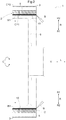
- FIG. 1 is a cross-sectional view of a rotor 1 (a rotor for a rotary electric machine) when seen in an axial direction L.
- the rotor 1 is configured to have a rotor core 2, permanent magnets 4, and a hub 9 (rotor support member) that supports the rotor core 2 and couples the rotor core 2 to a shaft (not shown) serving as a rotation axis X from a radial inner side R1.
- FIG. 2 is a cross-sectional view of the rotor core 2 in the axial direction L when the hub 9 is not attached to the rotor core 2.
- the rotor core 2 is formed by stacking a plurality of annular electromagnetic steel plates 3, and the electromagnetic steel plates 3 are joined to each other by welding before the hub 9 is attached to the rotor core 2.
- a symbol "W1" in FIG. 2 schematically indicates a joint portion (first joint portion) that has been melted and solidified by welding.
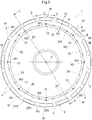
- FIG. 3 is a plan view of the rotor core 2 seen from a direction along the axial direction L.
- FIG. 1 shows a section passing through the first joint portion W1 before attaching the hub 9 to the rotor core 2.
- FIG. 1 shows a I-I section (a section passing through the second joint portion W2 and a buffer clearance G described below) in FIG. 3 after the hub 9 is attached to the rotor core 2.
- the rotor 1 according to the present embodiment will be described in detail.
- the "axial direction L", a "radial direction R", and a “circumferential direction C” are determined with reference to the shaft center the rotor core 2 (that is, the rotation axis X), unless otherwise specified.
- One side of the rotor core 2 in the radial direction R is set as a radial inner side R1, and the other side in the radial direction R is set as a radial outer side R2.
- the dimension of each member, the direction in which each member is disposed, and the position in which each member is disposed, and the like include a state in which there is a difference caused by errors (errors on a level allowable in manufacturing).
- the rotor 1 includes a cylindrical rotor core 2 having a plurality of magnet insertion holes 5, and a plurality of the permanent magnets 4 that are inserted into the magnet insertion holes 5, and is supported by the hub 9 from the radial inner side R1.
- the rotor core 2 that configures the rotor of the rotary electric machine is formed in a state of a stacked core in which a plurality of thin steel plates are stacked in a direction along the rotation axis, in order to reduce iron loss.
- the rotor core 2 is configured by stacking the electromagnetic steel plates 3 in the axial direction L.
- the rotor core 2 is fixed to the shaft (not shown) serving as the rotation axis X via the hub 9. As illustrated in FIG. 1 , the hub 9 abuts against an inner peripheral surface CP1, which is a peripheral surface of the rotor core 2 on the radial inner side R1 side, to support the rotor core 2 from the radial inner side R1.
- the hub 9 and the rotor core 2 are joined by welding and the rotor core 2 is supported so as not to be relatively moved to the hub 9.
- the hub 9 and the shaft (not shown) are coupled by shrink fitting, key connection, spline connection, or the like.
- the permanent magnets 4 are distributed in the circumferential direction C of the rotor core 2 so as to be dispersed.
- the magnet insertion holes 5 are arranged in the rotor core 2 along the circumferential direction.
- the permanent magnet 4 is disposed in each of the magnet insertion holes 5.
- the magnet insertion holes 5 extending through the rotor core 2 in the axial direction L are formed in the rotor core 2, and the permanent magnets 4 having approximately the same length in the axial direction L as the rotor core 2 are inserted into the magnet insertion holes 5 so as to be fixed to the rotor core 2.
- the rotor core 2 is configured by stacking the plurality of annular electromagnetic steel plates 3 in the axial direction L.
- the electromagnetic steel plates 3 that are adjacent in the axial direction L are joined to each other by welding.
- welded portions 10 for welding the electromagnetic steel plates 3 to each other are formed on the inner peripheral surface CP1 of the rotor core 2.
- An energy beam B such as an electron beam or a laser beam is emitted on the welded portions 10 to melt and then solidify the electromagnetic steel plates 3.
- the electromagnetic steel plates 3 that are adjacent in the axial direction L are welded.
- the energy beam B is emitted on the welded portions 10 along the axial direction L so as to join the electromagnetic steel plates 3 as one rotor core 2.
- the first joint portions W1 indicate parts in which the electromagnetic steel plates 3 are melted and solidified by the energy beam B that is emitted in the axial direction L.
- All parts of the welded portions 10 are each formed on the radial outer side R2 side with respect to a reference peripheral surface CR that is a peripheral surface of a general portion 20 of the inner peripheral surface CP1 of the rotor core 2 besides the welded portion 10.
- the reference peripheral surface CR corresponds to an inner wall of a virtual cylinder whose cross section with the rotation axis X as the center is a perfect circle. Since all parts of the welded portion 10 are each formed on the radial outer side R2 with respect to the reference peripheral surface CR, the first joint portions W1 are also formed on the radial outer side R2 with respect to the reference peripheral surface CR, and the first joint portions W1 do not hinder abutment between the hub 9 and the rotor core 2.
- the welded portion 10 is configured to have a first recessed groove portion 10a, a second recessed groove portion 10c, and a protruded portion 10b therebetween.
- the protruded portion 10b is formed so that a top portion, which is an end portion on the radial inner side R1, is positioned on the radial outer side R2 of the reference peripheral surface CR.
- the energy beam B is emitted with the top portion of the protruded portion 10b set as a target.
- the first recessed groove portion 10a and the second recessed groove portion 10c are formed on both sides of the protruded portion 10b in the circumferential direction C and are recessed toward the radial outer side R2.
- the first joint portion W1 is formed so as not to prevent the rotor core 2 and the hub 9 from being joined, without protruding to the radial inner side R1 of the reference peripheral surface CR.
- the hub 9 abuts against the general portion 20 and is fixed to the rotor core 2. Specifically, the hub 9 is fixed to the rotor core 2 while an outer peripheral surface 9A of the hub 9 abuts against the general portion 20 on the inner peripheral surface CP1 of the rotor core 2.
- the energy beam B is emitted on the parts in which the hub 9 and the general portion 20 abut, the hub 9 and the rotor core 2 are welded, and the second joint portions W2 are formed.
- one permanent magnet 4 forms one magnetic pole M, and a plurality of the magnetic poles M are arranged along the circumferential direction C.
- the second joint portions W2 are each formed in a partial region of the inner peripheral surface CP1 of the rotor core 2 in the circumferential direction C and are each disposed between two magnetic poles M that are adjacent in the circumferential direction C. Further, the second joint portions W2 are formed over the plurality of electromagnetic steel plates 3. As illustrated in FIG. 1 , a region in which the second joint portion W2 (melted joint portion) is formed in the axial direction L is referred to as an axial joint region JR.
- FIG. 5 is an enlarged plan view of the vicinity of the permanent magnet 4 of the rotor core 2.
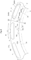
- FIG. 6 is a perspective view of the permanent magnet 4. As illustrated in FIG. 6 , each permanent magnet 4 has side surface portions 4a that are surfaces along the axial direction L and end surface portions 4b that are end surfaces in the axial direction L, and also has a plurality of corner portions 4c that are formed in a part in which the side surface portions 4a and the end surface portions 4b intersect.
- corner portions 4c At least one of the corner portions 4c that overlaps with the axial joint region JR when seen in the radial direction and that faces an outer peripheral surface CP2 of the rotor core 2 (faces the outer peripheral surface CP2 side of the rotor core 2) is referred to as a specific corner portion 4s.
- Each magnet insertion hole 5 has on the inner wall surface, facing surface portions 5p that are parts that face the corner portions 4c of the permanent magnet.
- the facing surface portion 5p that faces the specific corner portion 4s is referred to as a specific facing surface portion 5s.
- each clearance (G) that is formed between the specific corner portion 4s and the specific facing surface portion 5s is set to be a buffer clearance G that is larger than the clearances formed between the other corner portions 4c and the other facing surface portions 5p.
- the clearance (G) is a space formed between the corner portion 4c and the facing surface portion 5p.
- the corner portion 4c and the facing surface portion 5p face each other while no other member is disposed between the corner portion 4c and the facing surface portion 5p.
- the entire region sandwiched between the corner portion 4c and the facing surface portion 5p corresponds to the clearance (G).
- a length LG in the axial direction L of the region in which the buffer clearance G is formed is equal to or longer than a length LJ in the axial direction L of the axial joint region JR. Such a configuration is preferable in reducing tensile stress described below.
- the buffer clearances G are formed by forming chamfers 4g that are larger than the other corner portions 4c on the specific corner portion 4s of the permanent magnet 4, as illustrated in FIG. 6 . That is, by forming the chamfer 4g, it is possible to provide the buffer clearance G by setting the clearance formed between the specific corner portion 4s and the specific facing surface portion 5s to be larger than the clearance formed between the corner portions 4c excluding the specific corner portion 4s and the facing surface portions 5p.
- the permanent magnet 4 has a cross-sectional shape, which is orthogonal to the axial direction L, that is a rectangular shape.
- a "rectangular shape” is not limited to an accurate rectangular shape, but refers to a shape in which general shape is a rectangle.
- a "rectangular shape” also includes a shape in which one side is curved or a shape in which a spot corresponding to a corner of the rectangle is chamfered in a straight line or a curved line, when the general shape is assumed to be a rectangle, such as a shape in which the cross-sectional shape is a D-shape.
- the permanent magnet 4 having a rectangular cross-sectional shape has four side surface portions 4a and two end surface portions 4b since the general three-dimensional shape is a rectangular parallelepiped.
- the permanent magnet 4 has six side surface portions 4a when the cross-sectional shape is a D-shape (or a shape chamfered at positions corresponding to corners of the rectangle in the cross section).
- the side surface portion 4a indicated by a reference sign 43 is the side surface portion 4a (connection side surface portion 43) that connects the side surface portion 4a along the circumferential direction C indicated by a reference sign 41 (an outer peripheral side surface portion 41 (first main side surface portion) described below) and the side surface portion 4a along the radial direction R indicated by a reference sign 42 (a lateral side surface portion 42 (second main side surface portion)).
- connection side surface portion 43 can be included in the outer peripheral side surface portion 41 (first main side surface portion) or the lateral side surface portion 42 (second main side surface portion).
- the connection side surface portion 43 can be included in the outer peripheral side surface portion 41 (first main side surface portion) or the lateral side surface portion 42 (second main side surface portion).
- the general three-dimensional shape having four side surface portions 4a and two end surface portions 4b is a rectangular parallelepiped.
- the permanent magnet 4 having a rectangular cross-sectional shape orthogonal to the axial direction L of the permanent magnet 4 is disposed in the rotor core 2 so that the outer peripheral side surface portion 41 extends along the circumferential direction C.
- the outer peripheral side surface portion 41 is a surface that faces the outer peripheral surface CP2 (faces the outer peripheral surface CP2 side) of the rotor core 2, among the four side surface portions 4a.
- all the corner portions 4c (tetrahedral corner portions) in which the outer peripheral side surface portion 41 (including the connection side surface portions 43), other side portions 4a adjacent to the outer peripheral side surface portion 41 (here, the lateral side surface portions 42), and the end surface portions 4b intersect overlap with the axial joint regions JR.
- the buffer clearances G are each provided by forming the chamfer 4g on the specific corner portion 4s of the permanent magnet 4.
- the buffer clearances G may each be formed so that the specific facing surface portion 5s of the magnet insertion hole 5 is formed so as to have a shape recessed in the direction away from the permanent magnet 4 compared to the other facing surface portions 5p.
- the electromagnetic steel plates 3 that are the target be the electromagnetic steel plates 3 positioned on the axial end portion side in a range equal to or more than the length LJ of the axial joint region JR in the axial direction L. Further, it is preferable that the size in which the magnet insertion holes 5 are expanded increase toward the axial end portion.
- the form in which the buffer clearances G are provided by forming the chamfers 4g on the specific corner portions 4s of the permanent magnet 4, and the form in which the buffer clearances G are provided by expanding the magnet insertion holes 5, are each described above.
- the buffer clearances G may be provided by forming the chamfers 4g on the specific corner portions 4s of the permanent magnet 4 and expanding the magnet insertion holes 5.
- FIG. 8 illustrates an example in which the electromagnetic steel plates 3 are stacked, the electromagnetic steel plates 3 are joined together with the first joint portions W1, and the rotor core 2 is formed.
- the permanent magnet 4 is not inserted in the magnet insertion hole 5.
- the permanent magnet 4 is inserted in the rotor core 2 in FIG. 8 .
- the stacked electromagnetic steel plates 3 are compressed to each other along the axial direction L.
- the adhesive force between the stacked electromagnetic steel plates 3 is higher particularly at an axial center part compared to both end parts. Thus, deformation of each electromagnetic steel plate 3 is suppressed.
- such adhesive force is small. Thus, there is a possibility that the electromagnetic steel plates 3 are deformed toward the axial outer side and float up from other electromagnetic steel plates 3 and the like, due to the tensile force generated in the root parts of the bridge portions BR.
- the root parts of the bridge portions BR in the circumferential direction C do not abut against the permanent magnet 4 at the axial end portions, or the force acting between the root parts and the permanent magnet 4 becomes small even if the root parts abut against the permanent magnet 4.
- the root parts of the bridge portions BR are less susceptible to the reaction from the permanent magnet 4 at the axial end portions. As a result, tensile stress caused by contraction force and reaction force becomes small.
- each of the permanent magnets 4 is disposed in the rotor core 2 so that one surface (outer peripheral side surface portion 41) that faces the outer peripheral surface CP2 of the rotor core 2 extends along the circumferential direction C, among the four side surface portions 4a of the permanent magnet 4 with a rectangular cross-sectional shape orthogonal to the axial direction L.
- the buffer clearances G be provided as described above.
- FIG. 10 illustrates as an example, a form in which a pair of the permanent magnets 4 having a rectangular cross-sectional shape orthogonal to the axial direction L is disposed in the rotor core 2 so that the permanent magnets 4 are formed in a V-shape such that the distance between the permanent magnets 4 becomes closer toward the radial inner side R1 when seen in the axial direction.
- the magnet insertion holes 5 are formed so as to house the respective permanent magnets 4 with gaps serving as flux barriers.
- positioning portions 55 for disposing the permanent magnets 4 at prescribed positions in the magnet insertion holes 5 are formed in the magnet insertion holes 5.
- four positioning portions 55 are provided so that two surfaces of the four side surface portions 4a of each rectangular permanent magnet 4 abut against four corners (dihedral corner portions) that are adjacent thereto.
- the positioning portions 55 and the permanent magnets 4 abut against each other, reaction force from the permanent magnets 4 is applied to the positioning portions 55, when the contraction force of contracting from the radial outer side R2 toward the second joint portions W2 on the radial inner side R1 is generated. In this way, the positioning portions 55 receive tensile stress due to contraction force and reaction force.
- the buffer clearances G are formed between the facing surface portions 5p (specific facing surface portions 5s) of specific positioning portions 55s, which will be described below, and the specific corner portions 4s of the permanent magnets 4.
- all corner portions 4c that are corner portions 4c that face the positioning portions 55 which are formed in each of the magnet insertion holes 5 and position the permanent magnet 4 in the magnet insertion hole 5, that overlap with the axial joint regions JR when seen in the radial direction, and that face the outer peripheral surface CP2 of the rotor core 2 are set as the specific corner portions 4s.
- the positioning portions 55 facing the specific corner portion 4s are set as the specific positioning portions 55s.
- the buffer clearances G are formed by setting the clearances formed between the specific corner portions 4s and the specific facing surface portions 5s to be larger than the clearances formed between the corner portions 4c excluding the specific corner portions 4s and the facing surface portions 5p.
- FIG. 11 illustrates an example of a form in which the buffer clearances G are provided by forming the chamfers 4g on the specific corner portions 4s of each of the permanent magnets 4.
- FIG. 12 illustrates a form in which the buffer clearances G are provided by expanding each of the magnet insertion holes 5.
- the present invention is not limited to either one, and the buffer clearances G may be provided by forming the chamfers 4g on the specific corner portions 4s of the permanent magnets 4 and expanding the magnet insertion holes 5.
- the forms in which the buffer clearances G are provided are described above by illustrating examples of two forms of disposing the permanent magnets 4.
- tensile stress generated in the radial direction R of the rotor core 2 can be reduced by similarly providing the buffer clearances G. That is, among the corner portions 4c of the permanent magnets 4, at least one of the corner portions 4c that overlaps with the axial joint region JR when seen in the radial direction and that faces the outer peripheral surface CP2 of the rotor core 2 is set as the specific corner portion 4s.
- the facing surface portions 5p that face the specific corner portions 4s are set as the specific facing surface portions 5s.
- the buffer clearances G are provided between the specific corner portions 4s and the specific facing surface portions 5s. Thus, tensile stress can be reduced.
- the chamfers 4g are formed on the permanent magnets 4 having a D-shaped cross-sectional shape in the direction orthogonal to the axial direction L.
- the buffer clearances G can be formed by forming the chamfers 4g larger than the other corner portions 4c in the specific corner portions 4s, similar to the form described above.
- the chamfer 4g can be formed.
- FIG. 13 illustrates a case in which the cross-sectional shape is a rectangle
- FIG. 14 illustrates an example of a case in which the cross-sectional shape is a hexagon.
- the chamfers 4g larger than the chamfers formed on the other corner portions 4c are formed on the corner portions 4c (specific corner portion 4s) that overlap with the axial joint regions JR when seen in the radial direction and that face the outer peripheral surface CP2 of the rotor core 2, among the corner portions 4c of the permanent magnets 4.
- the buffer clearances G are formed.
- FIG. 15 and FIG. 16 a second embodiment of the rotor 1 will be described with reference to FIG. 15 and FIG. 16 .
- the corner portions 4c and the facing surface portions 5p face each other while no other members are disposed between the corner portions 4c and the facing surface portions 5p.
- the rotor 1 according to the present embodiment will be described focusing on the differences from the first embodiment. Points that are not particularly described are the same as those in the first embodiment.
- the clearances (G) formed between the corner portions 4c and the facing surface portions 5p are spaces formed in a part excluding the disposed members E, between the corner portions 4c and the facing surface portions 5p. That is, the clearances (G) formed between the corner portions 4c and the facing surface portions 5p are spaces in which there are no disposed members E and the bridge portion BR of the rotor core 2 is allowed to be deformed and moved. Also in this case, the clearances (G) formed between the specific corner portions 4s and the specific facing surface portions 5s are set to be the buffer clearances G that are larger than the clearances formed between the other corner portions 4c and the other facing surface portions 5p.
- the disposed members E are a fixing material F that is disposed between the inner wall surfaces of the magnet insertion holes 5 and the permanent magnets 4 to fix the permanent magnets 4 inside the respective magnet insertion holes 5.
- the fixing material F various known materials such as adhesives and various resins such as a thermoplastic resin, a thermosetting resin, and a foamable resin may be used.
- the fixing material F is a resin that is cured after being filled in a melted state between the inner wall surface of the magnet insertion holes 5 and the permanent magnets 4.
- the clearances (spaces) in which there are no fixing material F between the specific corner portions 4s and the specific facing surface portions 5s are set to be larger than the clearances (spaces) in which there is no fixing material F between the other corner portions 4c and the other facing surface portions 5p.
- the buffer clearances G are formed.
- the fixing material F is filled in parts between the inner wall portion of the magnet insertion hole 5 and the permanent magnet 4, while omitting the parts between the specific corner portions 4s and the specific facing surface portions 5s.
- the buffer clearances G are formed.
- the chamfers 4g larger than the chamfers formed on the other corner portions 4c are formed on the specific corner portions 4s of each permanent magnet 4.
- the distances between the specific corner portions 4s and the specific facing surface portions 5s are made larger than the distances between the corner portions 4c excluding the specific corner portions 4s and the facing surface portions 5p, so that larger buffer clearances G are more easily ensured.
- gaps defined by the inner wall surface of the magnet insertion hole 5 and the permanent magnet 4 that are spaced away from each other are formed on both sides of the permanent magnet 4 in the circumferential direction C.
- the gaps become fixing material filling portions 56 in which the fixing material F is filled.
- the fixing material filling portions 56 are formed continuously over the entire region of the magnet insertion hole 5 in the axial direction L.
- FIG. 16 illustrates the forming process of each buffer clearance G while focusing on a part corresponding to a XVI-XVI cross-section in FIG. 15 .
- the fixing material F is filled while the rotor core 2 is pressurized in the axial direction L by using a pressurizing member 8.
- the pressurizing member 8 has an abutting surface 81, a fixing material supply path 82, and a restricting protruded portion 83.
- the end surface on the other side of the rotor core 2 in the axial direction L is supported by a support member.
- the abutting surface 81 is a surface of the pressurizing member 8 that abuts against the end face of the rotor core 2 in the axial direction L.
- the pressurizing member 8 has a shape extending in the radial direction R and the circumferential direction C so as to cover the entire end surface of the rotor core 2 in the axial direction L. Accordingly, as illustrated in the middle drawing in FIG. 16 , the abutting surface 81 is formed so as to cover an opening portion of an end portion of the magnet insertion hole 5 in the axial direction L.
- the fixing material supply path 82 is a flow path for supplying the fixing material F to the magnet insertion hole 5.
- the fixing material supply path 82 is formed so as to extend through the pressurizing member 8 in the axial direction L.
- the opening portion of the fixing material supply path 82 on the abutting surface 81 side is provided at a position corresponding to the fixing material filling portion 56.
- the restricting protruded portion 83 is a protruded portion for restricting the fixing material F from entering, so as to form the buffer clearance G.
- the restricting protruded portion 83 has a shape that is protruded so as to fill at least a part of the space between the specific corner portion 4s and the specific facing surface portion 5s.
- the restricting protruded portion 83 has a shape corresponding to the entire space between the specific corner portion 4s and the specific facing surface portion 5s.
- the pressurizing member 8 is moved closer to the rotor core 2.
- the abutting surface 81 is abutted against the end surface of the rotor core 2 in the axial direction L and the rotor core 2 is pressurized in the axial direction L.
- the fixing material F in a flowable state is supplied to the fixing material supply path 82, as illustrated in the middle drawing in FIG. 16 .
- the fixing material supply path 82 is opened at a position corresponding to the fixing material filling portion 56 of the magnet insertion hole 5.
- the fixing material F is first supplied to the fixing material filling portion 56 and then to each portion in the magnet insertion hole 5. In this way, the fixing material F is filled between the inner wall surface of the magnet insertion hole 5 and the permanent magnet 4. At this time, since the restricting protruded portion 83 is disposed so as to fill the space between the specific corner portion 4s and the specific facing surface portion 5s, the fixing material F is restricted from entering the region between the specific corner portion 4s and the specific facing surface portion 5s. Then, after the fixing material F is cured, the pressurizing member 8 is detached from the rotor core 2, as illustrated in the bottom drawing in FIG. 16 .
- the buffer clearance G in which there is no fixing material F is formed in the space corresponding to the restricting protruded portion 83.
- the fixing material F is filled while the abutting surface 81 is abutted against the end surface of the rotor core 2 in the axial direction L and the rotor core 2 is pressurized by the pressurizing member 8 in the axial direction L.
- the buffer clearances G are formed between the specific corner portions 4s and the specific facing surface portions 5s.
- the fixing material F is filled between the inner wall surfaces of the magnet insertion holes 5 and the permanent magnets 4, it is possible to suppress the movement of the bridge portions BR to the radial inner side R1 with the fixing material F. Therefore, similar to the case of the first embodiment, when the rotor core 2 and the hub 9 are joined by the second joint portions W2 (melted joint portions), tensile stress that causes partial deformation of the rotor core 2 can be reduced.
- the fixing material F is suppressed from entering the entire space between the specific corner portions 4s and the specific facing surface portions 5s.
- the present invention is not limited to this, and the fixing material F may be disposed in a part of the space between the specific corner portions 4s and the specific facing surface portions 5s.
- the buffer clearances G formed between the specific corner portions 4s and the specific facing surface portions 5s are set to be larger than the clearances formed between the other corner portions 4c and the other facing surface portions 5p.
- a configuration is described as an example in which chamfers 4g that are larger than chamfers formed on the other corner portions 4c are formed on the specific corner portions 4s of the permanent magnets 4.
- the configuration is not limited to this.
- the specific facing surface portions 5s of each magnet insertion hole 5 may be formed so as to have a shape recessed in the direction away from the permanent magnet 4 compared to the other facing surface portions 5p, or the chamfers 4g may be formed on the specific corner portions 4s of the permanent magnet 4 and the specific facing surface portions 5s of the magnet insertion hole 5 may be expanded so as to be recessed.
- intervals at which the specific corner portions 4s and the specific facing surface portions 5s face each other maybe configured to be similar to intervals at which the other corner portions 4c and the other facing surface portions 5p face each other, and the buffer clearances G may be formed depending on the disposition state of the disposed members E such as the fixing material F.
- the spaces (buffer clearances G) formed in parts excluding the disposed members E, between the specific corner portions 4s and the specific facing surface portions 5s are set to be larger than the spaces formed in part excluding the disposed members E, between the other corner portions 4c and the other facing surface portions 5p.
- such a configuration can be realized by not filling the fixing material F as the disposed members E between the specific corner portions 4s and the specific facing surface portions 5s, and filling the fixing material F between the other corner portions 4c and the other facing surface portions 5p.
- the rotor (1) for a rotary electric machine is provided with a cylindrical rotor core (2) that is configured by stacking electromagnetic steel plates (3) in an axial direction (L) and that has a plurality of magnet insertion holes (5), and provided with a plurality of permanent magnets (4) that are inserted in the magnet insertion holes (5), and supported by a rotor support member (9) from a radial inner side (R1), in which each of the magnet insertion holes (5) is formed to extend in the axial direction (L), and the magnet insertion holes (5) are arranged along a circumferential direction (C), each of the permanent magnets (4) has a side surface portion (4a) that is a surface along the axial direction (L), and an end surface portion (4b) that is an end surface in the axial direction (L), and has a plurality of corner portions (4c) formed in a part in which the side surface portion (4a) and the end surface portion (4b) intersect, a melted joint portion (W2) is formed on an end
- the clearance (G) that is larger than the clearance formed between the other corner portion (4c) and the facing surface portion (5p) is formed between the specific corner portion (4s) and the specific facing surface portion (5s).
- the clearance (G) be a space formed between the corner portion (4c) and the facing surface portion (5p), and when there is another disposed member (E) between the corner portion (4c) and the facing surface portion (5p), the clearance (G) be a space formed in a part excluding the disposed member (E), between the corner portion (4c) and the facing surface portion (5p).
- the disposed member (E) be a fixing material (F) disposed between the inner wall surface of the magnet insertion hole (5) and the permanent magnet (4) to fix the permanent magnet (4) inside the magnet insertion hole (5).
- a chamfer (4g) larger than a chamfer formed in the other corner portion (4c) be formed in the specific corner portion (4s) of the permanent magnet (4).
- the specific facing surface portion (5s) of the magnet insertion hole (5) be formed so as to be a shape recessed toward a direction away from the permanent magnet (4) compared to the other facing surface portion (5p).
- a length (LG) in the axial direction (L) of a region in which a clearance (G) between the specific corner portion (4s) and the specific facing surface portion (5s) is formed be larger than a clearance between the other corner portion (4c) and the other facing surface portion (4p), be equal to or more than a length (LJ) in the axial direction (L) of the axial joint region (JR).
- contraction force from the radial outer side (R2) toward the radial inner side (R1) is generated in the rotor core (2) from the radial outer side (R2) to the melted joint portion (W2)
- contraction force in a range in the axial direction (L) in which the melted joint portion (W2) is formed can be easily increased.
- the clearance (G) between the specific corner portion (4s) and the specific facing surface portion (5s) be expanded so as to include the range in the axial direction (L) in which the melted joint portion (W2) is formed.
- a cross-sectional shape of the permanent magnet (4) orthogonal to the axial direction (L) be a rectangular shape, and the permanent magnet (4) be disposed in the rotor core (2) so that an outer peripheral side surface portion (41) that is one surface facing the outer peripheral surface (CP2) of the rotor core (2) among the four side surface portions (4a) extends along the circumferential direction (C), and among the corner portions (4c) formed in a part in which the outer peripheral side surface portion (41), other side surface portions (4a) adjacent to the outer peripheral side surface portion (41), and the end surface portion (4b) intersect, all of the corner portions (4c) that overlap with the axial joint region (JR) when seen in the radial direction be set as the specific corner portion (4s).
- a cross-sectional shape of the permanent magnet (4) orthogonal to the axial direction (L) be a rectangular shape, and the permanent magnet (4) be disposed in the rotor core (2) so that a pair of the permanent magnets (4) is disposed in a V-shape such that a distance between the permanent magnets (4) is reduced as the permanent magnets (4) extend toward the radial inner side (R1), and all of the corner portions (4c) that each face a positioning portion (55) formed in the magnet insertion hole (5) and which positions the permanent magnet (4), that overlap with the axial joint region (JR) when seen in the radial direction, and that face the outer peripheral surface (CP2) of the rotor core (2) be set as the specific corner portion (4s).
- one magnetic pole (M) be configured of at least one permanent magnet (4) and a plurality of magnetic poles (M) be arranged along the circumferential direction (C), and the melted joint portion (W2) be formed in a partial region of the inner peripheral surface (CP1) of the rotor core (2) in the circumferential direction (C), and be disposed between two magnetic poles (M) that are adjacent in the circumferential direction (C).
- the melted joint portion (W2) be provided between the adjacent magnetic poles (M) so as not to be a resistance of a magnetic path that is a path of a magnetic flux.
- the melted joint portion (W2) is disposed between the magnetic poles (M)
- the bridge portion (BR) is a part that is positioned on the radial outer side (R2) of the magnet insertion hole (5) in the rotor core (2) and that has a thin radial width.
Landscapes
- Engineering & Computer Science (AREA)
- Power Engineering (AREA)
- Permanent Field Magnets Of Synchronous Machinery (AREA)
- Iron Core Of Rotating Electric Machines (AREA)
Abstract
Description
- The present invention is related to a rotor for a rotary electric machine that is provided with a cylindrical rotor core configured by stacking electromagnetic steel plates in an axial direction and having a plurality of magnet insertion holes, and a plurality of permanent magnets inserted into the magnet insertion holes, and that is supported from a radial inner side by a rotor supporting member.
- Japanese Unexamined Patent Application Publication No.
2015-119557 JP 2015-119557 A - When the rotor core (20) and the shaft body (10) are joined by welding in this way, a force of contracting from the radial outer side toward a welding spot on the radial inner side tends to be generated in the rotor core (20) due to the contraction of the melted metal. In the rotor core (20), a part positioned on the radial outer side of the magnet insertion hole (24) and having a smaller radial width, that is, a so-called bridge portion is also pulled toward the radial inner side. However, since the permanent magnet (26) is inserted in the magnet insertion hole (24), the movement of the bridge portion to the radial inner side is prevented by the permanent magnet (26). Thus, the part of the bridge portion that abuts against the permanent magnet (26) receives from the permanent magnet (26) side, a force caused by a reaction of a force of contracting toward the radial inner side. Therefore, a large tensile stress may act on root parts positioned at end portions of the bridge portion in the circumferential direction. In the electromagnetic steel plates (23) stacked in the axial direction, an adhesive force between the electromagnetic steel plates (23) in the axial direction near end portions of the rotor core (20) in the axial direction is small. Thus, depending on a stress generated in the rotor core (20), a partial deformation such as lifting of the electromagnetic steel plates (23) easily occurs around the bridge portions near the end portions in the axial direction.
- Patent Document 1: Japanese Unexamined Patent Application Publication No.
2015-119557 JP 2015-119557 A - In view of the above circumstances, when the rotor core and the rotor support member are joined by the melted joining part, it is desired that tensile stress that causes the partial deformation of the rotor core be reduced.
- In one aspect, in view of the above, a rotor for a rotary electric machine is a rotor provided with a cylindrical rotor core that is configured by stacking electromagnetic steel plates in an axial direction and that has a plurality of magnet insertion holes, and provided with a plurality of permanent magnets that are inserted in the magnet insertion holes, and supported by a rotor support member from a radial inner side. Each of the magnet insertion holes is formed to extend in the axial direction, and the magnet insertion holes are arranged along a circumferential direction. Each of the permanent magnets has a side surface portion that is a surface along the axial direction, and an end surface portion that is an end surface in the axial direction, and has a plurality of corner portions formed in a part in which the side surface portion and the end surface portion intersect. A melted joint portion is formed on an end portion in the axial direction on an inner peripheral surface of the rotor core, and the rotor core is joined to the rotor support member at the melted joint portion. A region in the axial direction in which the melted joint portion is formed is set as an axial joint region. Among the corner portions of the permanent magnet, at least one corner portion that overlaps with the axial joint region when seen in a radial direction and that faces an outer peripheral surface of the rotor core is set as a specific corner portion. Parts on an inner wall surface of the magnet insertion hole that face the respective corner portions are set as facing surface portions, and among a plurality of the facing surface portions, the facing surface portion that faces the specific corner portion is set as a specific facing surface portion. A clearance formed between the specific corner portion and the specific facing surface portion is larger than a clearance formed between another corner portion and another facing surface portion.
- According to the configuration, a clearance that is larger than a clearance formed between the other corner portion and the other facing surface portion is formed between the specific corner portion and the specific facing surface portion. Thus, in the vicinity of the specific corner portion of the permanent magnet, it is possible to make it difficult for the inner wall surface of the magnet insertion hole and the permanent magnet to abut against each other. In this way, even if contraction force is generated in the rotor core from the radial outer side toward the melted joint portion on the radial inner side, reaction force from the permanent magnet side caused by contraction force is reduced. That is, tensile stress in the rotor core caused by contraction force and reaction force is also reduced. Therefore, according to the present configuration, when the rotor core and the rotor support member are joined by the melted joint portion, it is possible to reduce tensile stress that causes partial deformation of the rotor core.
- Further features and advantages of the rotor for a rotary electric machine will be apparent from the following description of embodiments that will be described with reference to the drawings.
-
- [
FIG. 1] FIG. 1 is a cross-sectional view of a rotor in a rotational axis direction. - [
FIG. 2] FIG. 2 is a cross-sectional view of a rotor core in the rotational axis direction. - [
FIG. 3] FIG. 3 is a plan view of the rotor when seen in an axial direction. - [
FIG. 4] FIG. 4 is an enlarged plan view of the rotor core when seen in the axial direction. - [
FIG. 5] FIG. 5 is an enlarged plan view of the vicinity of a permanent magnet of the rotor core when seen in the axial direction. - [
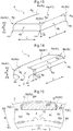
FIG. 6] FIG. 6 is a perspective view of the permanent magnet. - [
FIG. 7] FIG. 7 is an enlarged plan view of the vicinity of a permanent magnet of a rotor core of another example when seen in the axial direction. - [
FIG. 8] FIG. 8 is an enlarged plan view of the vicinity of a magnet insertion hole of a rotor core of a comparative example when seen in the axial direction. - [
FIG. 9] FIG. 9 is an enlarged plan view of the vicinity of a permanent magnet of the rotor core of the comparative example when seen in the axial direction. - [
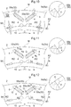
FIG. 10] FIG. 10 is an enlarged plan view of an example of a rotor core in which the permanent magnets are disposed in a V-shape when seen in the axial direction. - [
FIG. 11] FIG. 11 is an enlarged plan view of an example in which a cushioning clearance is provided with respect toFIG. 10 . - [
FIG. 12] FIG. 12 is an enlarged plan view of another example in which a cushioning clearance is provided with respect toFIG. 10 . - [
FIG. 13] FIG. 13 is a perspective view of another example of a permanent magnet. - [
FIG. 14] FIG. 14 is a perspective view of yet another examples of a permanent magnet. - [
FIG. 15] FIG. 15 is an enlarged plan view of the vicinity of a permanent magnet of a rotor core according to a second embodiment when seen in the axial direction. - [
FIG. 16] FIG. 16 is an explanatory view of a process of forming a buffer clearance G of the rotor core according to a second embodiment. - [
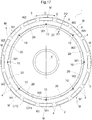
FIG. 17] FIG. 17 is a plan view of another form of a rotor when seen in the axial direction. - Hereinafter, a first embodiment of a rotor for a rotary electric machine will be described with reference to the drawings.
FIG. 1 is a cross-sectional view of a rotor 1 (a rotor for a rotary electric machine) when seen in an axial direction L. Therotor 1 is configured to have arotor core 2,permanent magnets 4, and a hub 9 (rotor support member) that supports therotor core 2 and couples therotor core 2 to a shaft (not shown) serving as a rotation axis X from a radial inner side R1.FIG. 2 is a cross-sectional view of therotor core 2 in the axial direction L when thehub 9 is not attached to therotor core 2. Although details will be described later, therotor core 2 is formed by stacking a plurality of annularelectromagnetic steel plates 3, and theelectromagnetic steel plates 3 are joined to each other by welding before thehub 9 is attached to therotor core 2. A symbol "W1" inFIG. 2 schematically indicates a joint portion (first joint portion) that has been melted and solidified by welding.FIG. 3 is a plan view of therotor core 2 seen from a direction along the axial direction L. - In the present embodiment, after the
electromagnetic steel plates 3 forming therotor core 2 are joined to each other by welding, thehub 9 is attached to therotor core 2, and thehub 9 and therotor core 2 are joined by welding.
A symbol "W2" inFIG. 1 schematically indicates a joint portion (second joint portion (melted joint portion)) that has been melted and solidified by welding. As described above, theelectromagnetic steel plates 3 of therotor core 2 are welded to each other first and then therotor core 2 and thehub 9 are welded.FIG. 2 shows a section passing through the first joint portion W1 before attaching thehub 9 to therotor core 2.FIG. 1 shows a I-I section (a section passing through the second joint portion W2 and a buffer clearance G described below) inFIG. 3 after thehub 9 is attached to therotor core 2. - Hereinafter, the
rotor 1 according to the present embodiment will be described in detail. In the following description, the "axial direction L", a "radial direction R", and a "circumferential direction C" are determined with reference to the shaft center the rotor core 2 (that is, the rotation axis X), unless otherwise specified. One side of therotor core 2 in the radial direction R is set as a radial inner side R1, and the other side in the radial direction R is set as a radial outer side R2. The dimension of each member, the direction in which each member is disposed, and the position in which each member is disposed, and the like include a state in which there is a difference caused by errors (errors on a level allowable in manufacturing). When the singlepermanent magnet 4 is indicated, the direction in a state in which thepermanent magnet 4 is attached to therotor core 2 is indicated. - As illustrated in
FIG. 1 andFIG. 3 , therotor 1 includes acylindrical rotor core 2 having a plurality of magnet insertion holes 5, and a plurality of thepermanent magnets 4 that are inserted into the magnet insertion holes 5, and is supported by thehub 9 from the radial inner side R1. In many cases, therotor core 2 that configures the rotor of the rotary electric machine is formed in a state of a stacked core in which a plurality of thin steel plates are stacked in a direction along the rotation axis, in order to reduce iron loss. In the present embodiment, as illustrated inFIG. 1 andFIG. 2 , therotor core 2 is configured by stacking theelectromagnetic steel plates 3 in the axial direction L. Therotor core 2 is fixed to the shaft (not shown) serving as the rotation axis X via thehub 9. As illustrated inFIG. 1 , thehub 9 abuts against an inner peripheral surface CP1, which is a peripheral surface of therotor core 2 on the radial inner side R1 side, to support therotor core 2 from the radial inner side R1. Thehub 9 and therotor core 2 are joined by welding and therotor core 2 is supported so as not to be relatively moved to thehub 9. Thehub 9 and the shaft (not shown) are coupled by shrink fitting, key connection, spline connection, or the like. - As illustrated in
FIG. 3 , thepermanent magnets 4 are distributed in the circumferential direction C of therotor core 2 so as to be dispersed. The magnet insertion holes 5 are arranged in therotor core 2 along the circumferential direction. Thepermanent magnet 4 is disposed in each of the magnet insertion holes 5. Here, the magnet insertion holes 5 extending through therotor core 2 in the axial direction L are formed in therotor core 2, and thepermanent magnets 4 having approximately the same length in the axial direction L as therotor core 2 are inserted into the magnet insertion holes 5 so as to be fixed to therotor core 2. - As described above, the
rotor core 2 is configured by stacking the plurality of annularelectromagnetic steel plates 3 in the axial direction L. In order to fix theelectromagnetic steel plates 3, theelectromagnetic steel plates 3 that are adjacent in the axial direction L are joined to each other by welding. Thus, weldedportions 10 for welding theelectromagnetic steel plates 3 to each other are formed on the inner peripheral surface CP1 of therotor core 2. - An energy beam B such as an electron beam or a laser beam is emitted on the welded
portions 10 to melt and then solidify theelectromagnetic steel plates 3. Thus, theelectromagnetic steel plates 3 that are adjacent in the axial direction L are welded. As illustrated inFIG. 2 , the energy beam B is emitted on the weldedportions 10 along the axial direction L so as to join theelectromagnetic steel plates 3 as onerotor core 2. The first joint portions W1 indicate parts in which theelectromagnetic steel plates 3 are melted and solidified by the energy beam B that is emitted in the axial direction L. - All parts of the welded
portions 10 are each formed on the radial outer side R2 side with respect to a reference peripheral surface CR that is a peripheral surface of ageneral portion 20 of the inner peripheral surface CP1 of therotor core 2 besides the weldedportion 10. In other words, the reference peripheral surface CR corresponds to an inner wall of a virtual cylinder whose cross section with the rotation axis X as the center is a perfect circle. Since all parts of the weldedportion 10 are each formed on the radial outer side R2 with respect to the reference peripheral surface CR, the first joint portions W1 are also formed on the radial outer side R2 with respect to the reference peripheral surface CR, and the first joint portions W1 do not hinder abutment between thehub 9 and therotor core 2. - As illustrated in
FIG. 4 , the weldedportion 10 is configured to have a first recessedgroove portion 10a, a second recessedgroove portion 10c, and a protrudedportion 10b therebetween. The protrudedportion 10b is formed so that a top portion, which is an end portion on the radial inner side R1, is positioned on the radial outer side R2 of the reference peripheral surface CR. The energy beam B is emitted with the top portion of the protrudedportion 10b set as a target. The first recessedgroove portion 10a and the second recessedgroove portion 10c are formed on both sides of the protrudedportion 10b in the circumferential direction C and are recessed toward the radial outer side R2. Thus, the possibility that the meltedelectromagnetic steel plates 3 protrudes to the radial inner side R1 is low. Therefore, the first joint portion W1 is formed so as not to prevent therotor core 2 and thehub 9 from being joined, without protruding to the radial inner side R1 of the reference peripheral surface CR. - The
hub 9 abuts against thegeneral portion 20 and is fixed to therotor core 2. Specifically, thehub 9 is fixed to therotor core 2 while an outerperipheral surface 9A of thehub 9 abuts against thegeneral portion 20 on the inner peripheral surface CP1 of therotor core 2. As illustrated inFIG. 1 andFIG. 3 , at both end portions in the axial direction L, the energy beam B is emitted on the parts in which thehub 9 and thegeneral portion 20 abut, thehub 9 and therotor core 2 are welded, and the second joint portions W2 are formed. As illustrated inFIG. 3 , here, onepermanent magnet 4 forms one magnetic pole M, and a plurality of the magnetic poles M are arranged along the circumferential direction C. The second joint portions W2 are each formed in a partial region of the inner peripheral surface CP1 of therotor core 2 in the circumferential direction C and are each disposed between two magnetic poles M that are adjacent in the circumferential direction C. Further, the second joint portions W2 are formed over the plurality ofelectromagnetic steel plates 3. As illustrated inFIG. 1 , a region in which the second joint portion W2 (melted joint portion) is formed in the axial direction L is referred to as an axial joint region JR. -
FIG. 5 is an enlarged plan view of the vicinity of thepermanent magnet 4 of therotor core 2.FIG. 6 is a perspective view of thepermanent magnet 4. As illustrated inFIG. 6 , eachpermanent magnet 4 hasside surface portions 4a that are surfaces along the axial direction L and endsurface portions 4b that are end surfaces in the axial direction L, and also has a plurality ofcorner portions 4c that are formed in a part in which theside surface portions 4a and theend surface portions 4b intersect. Among thecorner portions 4c, at least one of thecorner portions 4c that overlaps with the axial joint region JR when seen in the radial direction and that faces an outer peripheral surface CP2 of the rotor core 2 (faces the outer peripheral surface CP2 side of the rotor core 2) is referred to as aspecific corner portion 4s. - Each
magnet insertion hole 5 has on the inner wall surface, facingsurface portions 5p that are parts that face thecorner portions 4c of the permanent magnet. Among a plurality of the facingsurface portions 5p that face thecorner portions 4c, the facingsurface portion 5p that faces thespecific corner portion 4s is referred to as a specific facingsurface portion 5s. In the present embodiment, each clearance (G) that is formed between thespecific corner portion 4s and the specific facingsurface portion 5s is set to be a buffer clearance G that is larger than the clearances formed between theother corner portions 4c and the other facingsurface portions 5p. Here, the clearance (G) is a space formed between thecorner portion 4c and the facingsurface portion 5p. In the present embodiment, thecorner portion 4c and the facingsurface portion 5p face each other while no other member is disposed between thecorner portion 4c and the facingsurface portion 5p. Thus, the entire region sandwiched between thecorner portion 4c and the facingsurface portion 5p corresponds to the clearance (G). In the present embodiment, a length LG in the axial direction L of the region in which the buffer clearance G is formed is equal to or longer than a length LJ in the axial direction L of the axial joint region JR. Such a configuration is preferable in reducing tensile stress described below. - In the embodiment illustrated in
FIG. 5 , the buffer clearances G are formed by formingchamfers 4g that are larger than theother corner portions 4c on thespecific corner portion 4s of thepermanent magnet 4, as illustrated inFIG. 6 . That is, by forming thechamfer 4g, it is possible to provide the buffer clearance G by setting the clearance formed between thespecific corner portion 4s and the specific facingsurface portion 5s to be larger than the clearance formed between thecorner portions 4c excluding thespecific corner portion 4s and the facingsurface portions 5p. - In the present embodiment, the
permanent magnet 4 has a cross-sectional shape, which is orthogonal to the axial direction L, that is a rectangular shape. A "rectangular shape" is not limited to an accurate rectangular shape, but refers to a shape in which general shape is a rectangle. For example, as illustrated inFIG. 3 to FIG. 6 , a "rectangular shape" also includes a shape in which one side is curved or a shape in which a spot corresponding to a corner of the rectangle is chamfered in a straight line or a curved line, when the general shape is assumed to be a rectangle, such as a shape in which the cross-sectional shape is a D-shape. Thepermanent magnet 4 having a rectangular cross-sectional shape has fourside surface portions 4a and twoend surface portions 4b since the general three-dimensional shape is a rectangular parallelepiped. - As illustrated in
FIG. 6 , thepermanent magnet 4 has sixside surface portions 4a when the cross-sectional shape is a D-shape (or a shape chamfered at positions corresponding to corners of the rectangle in the cross section). Theside surface portion 4a indicated by areference sign 43 is theside surface portion 4a (connection side surface portion 43) that connects theside surface portion 4a along the circumferential direction C indicated by a reference sign 41 (an outer peripheral side surface portion 41 (first main side surface portion) described below) and theside surface portion 4a along the radial direction R indicated by a reference sign 42 (a lateral side surface portion 42 (second main side surface portion)). Thus, the connectionside surface portion 43 can be included in the outer peripheral side surface portion 41 (first main side surface portion) or the lateral side surface portion 42 (second main side surface portion). Viewed in this way, as illustrated inFIG. 6 , it can be said that for thepermanent magnet 4 in which the cross-cross-sectional shape is a D-shape (or a shape in which the places corresponding to the corners of the rectangle in the cross-section are chamfered), the general three-dimensional shape having fourside surface portions 4a and twoend surface portions 4b is a rectangular parallelepiped. - In the present embodiment, the
permanent magnet 4 having a rectangular cross-sectional shape orthogonal to the axial direction L of thepermanent magnet 4 is disposed in therotor core 2 so that the outer peripheralside surface portion 41 extends along the circumferential direction C. The outer peripheralside surface portion 41 is a surface that faces the outer peripheral surface CP2 (faces the outer peripheral surface CP2 side) of therotor core 2, among the fourside surface portions 4a. Here, all thecorner portions 4c (tetrahedral corner portions) in which the outer peripheral side surface portion 41 (including the connection side surface portions 43),other side portions 4a adjacent to the outer peripheral side surface portion 41 (here, the lateral side surface portions 42), and theend surface portions 4b intersect overlap with the axial joint regions JR. Thus, it is preferable that all of thesecorner portions 4c be set as thespecific corner portions 4s. - In the above description, referring to
FIG. 5 , an example is indicated in which the buffer clearances G are each provided by forming thechamfer 4g on thespecific corner portion 4s of thepermanent magnet 4. However, as illustrated inFIG. 7 , the buffer clearances G may each be formed so that the specific facingsurface portion 5s of themagnet insertion hole 5 is formed so as to have a shape recessed in the direction away from thepermanent magnet 4 compared to the other facingsurface portions 5p. When the buffer clearances G are formed by expanding themagnet insertion hole 5, the magnet insertion holes 5 of theelectromagnetic steel plates 3 positioned at each of the end portions in the axial direction L may be expanded. It is preferable that theelectromagnetic steel plates 3 that are the target be theelectromagnetic steel plates 3 positioned on the axial end portion side in a range equal to or more than the length LJ of the axial joint region JR in the axial direction L. Further, it is preferable that the size in which the magnet insertion holes 5 are expanded increase toward the axial end portion. - The form in which the buffer clearances G are provided by forming the
chamfers 4g on thespecific corner portions 4s of thepermanent magnet 4, and the form in which the buffer clearances G are provided by expanding the magnet insertion holes 5, are each described above. However, the present invention is not limited to either one. The buffer clearances G may be provided by forming thechamfers 4g on thespecific corner portions 4s of thepermanent magnet 4 and expanding the magnet insertion holes 5. - Here, the effects of the buffer clearance G will be described with reference to
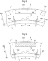
FIG. 8 and FIG. 9. FIG. 8 illustrates an example in which theelectromagnetic steel plates 3 are stacked, theelectromagnetic steel plates 3 are joined together with the first joint portions W1, and therotor core 2 is formed. InFIG. 8 , thepermanent magnet 4 is not inserted in themagnet insertion hole 5. InFIG. 9 , thepermanent magnet 4 is inserted in therotor core 2 inFIG. 8 . - As described above, when the
rotor core 2 and thehub 9 are joined by welding, as illustrated inFIG. 8 and FIG. 9 , a force of contracting from the radial outer side R2 toward the second joint portion W2 on the radial inner side R1 tends to be generated in therotor core 2. As illustrated inFIG. 8 , the part positioned on the radial outer side R2 of themagnet insertion hole 5 in therotor core 2, that is, a so-called bridge portion BR is also pulled toward the radial inner side R1. When thepermanent magnet 4 is not inserted in themagnet insertion hole 5, there is a possibility that themagnet insertion hole 5 is deformed by the force. In such a case, as shown by a broken line inFIG. 8 for example, the facingsurface portions 5p on the radial outer side R2 of themagnet insertion hole 5 may be moved to the radial inner side R1. - In contrast, when the
permanent magnet 4 is inserted in themagnet insertion hole 5, the inner wall of themagnet insertion hole 5 on the radial outer side R2 abuts against thepermanent magnet 4. Thus, the movement of the bridge portion BR toward the radial inner side R1 is prevented by thepermanent magnet 4. The inner wall of themagnet insertion hole 5 on the radial outer side R2 that abuts against thepermanent magnet 4 thus receives a force from thepermanent magnet 4 resulting from a reaction of the force of contracting toward the radial inner side R1. The force of contracting and the force resulting from the reaction are opposite directions from each other. A large tensile stress may act on root parts positioned at the end portions of the bridge portion BR in the circumferential direction C. The stackedelectromagnetic steel plates 3 are compressed to each other along the axial direction L. The adhesive force between the stackedelectromagnetic steel plates 3 is higher particularly at an axial center part compared to both end parts. Thus, deformation of eachelectromagnetic steel plate 3 is suppressed. However, in theelectromagnetic steel plates 3 positioned at the axial end portions, such adhesive force is small. Thus, there is a possibility that theelectromagnetic steel plates 3 are deformed toward the axial outer side and float up from otherelectromagnetic steel plates 3 and the like, due to the tensile force generated in the root parts of the bridge portions BR. - Here, as illustrated in
FIG. 5 and FIG. 7 , when the buffer clearances G are formed, the root parts of the bridge portions BR in the circumferential direction C do not abut against thepermanent magnet 4 at the axial end portions, or the force acting between the root parts and thepermanent magnet 4 becomes small even if the root parts abut against thepermanent magnet 4. Thus, even if contraction force is generated in therotor core 2, the root parts of the bridge portions BR are less susceptible to the reaction from thepermanent magnet 4 at the axial end portions. As a result, tensile stress caused by contraction force and reaction force becomes small. - In the above description, a form is indicated as an example in which each of the
permanent magnets 4 is disposed in therotor core 2 so that one surface (outer peripheral side surface portion 41) that faces the outer peripheral surface CP2 of therotor core 2 extends along the circumferential direction C, among the fourside surface portions 4a of thepermanent magnet 4 with a rectangular cross-sectional shape orthogonal to the axial direction L. However, how thepermanent magnets 4 are disposed in therotor core 2 is not limited to this form, and even if thepermanent magnets 4 are disposed in another manner, it is preferable that the buffer clearances G be provided as described above. -
FIG. 10 illustrates as an example, a form in which a pair of thepermanent magnets 4 having a rectangular cross-sectional shape orthogonal to the axial direction L is disposed in therotor core 2 so that thepermanent magnets 4 are formed in a V-shape such that the distance between thepermanent magnets 4 becomes closer toward the radial inner side R1 when seen in the axial direction. In this form, the magnet insertion holes 5 are formed so as to house the respectivepermanent magnets 4 with gaps serving as flux barriers. Thus,positioning portions 55 for disposing thepermanent magnets 4 at prescribed positions in the magnet insertion holes 5 are formed in the magnet insertion holes 5. Here, fourpositioning portions 55 are provided so that two surfaces of the fourside surface portions 4a of each rectangularpermanent magnet 4 abut against four corners (dihedral corner portions) that are adjacent thereto. - As described above with reference to
FIG. 8 and FIG. 9 , if thepositioning portions 55 and thepermanent magnets 4 abut against each other, reaction force from thepermanent magnets 4 is applied to thepositioning portions 55, when the contraction force of contracting from the radial outer side R2 toward the second joint portions W2 on the radial inner side R1 is generated. In this way, thepositioning portions 55 receive tensile stress due to contraction force and reaction force. Thus, among the positioningportions 55, the buffer clearances G are formed between the facingsurface portions 5p (specific facingsurface portions 5s) ofspecific positioning portions 55s, which will be described below, and thespecific corner portions 4s of thepermanent magnets 4. - As illustrated in
FIG. 11 and FIG. 12 , allcorner portions 4c that arecorner portions 4c that face thepositioning portions 55 which are formed in each of the magnet insertion holes 5 and position thepermanent magnet 4 in themagnet insertion hole 5, that overlap with the axial joint regions JR when seen in the radial direction, and that face the outer peripheral surface CP2 of therotor core 2 are set as thespecific corner portions 4s. Thepositioning portions 55 facing thespecific corner portion 4s are set as thespecific positioning portions 55s. Although not shown, there are also specific facingsurface portions 5s on thepositioning portions 55s. As described above, the buffer clearances G are formed by setting the clearances formed between thespecific corner portions 4s and the specific facingsurface portions 5s to be larger than the clearances formed between thecorner portions 4c excluding thespecific corner portions 4s and the facingsurface portions 5p. - Similar to the form described above with reference to
FIG. 5 and FIG. 6 ,FIG. 11 illustrates an example of a form in which the buffer clearances G are provided by forming thechamfers 4g on thespecific corner portions 4s of each of thepermanent magnets 4. Similar to the form described above with reference toFIG. 7 ,FIG. 12 illustrates a form in which the buffer clearances G are provided by expanding each of the magnet insertion holes 5. In such a case, it is possible to expand themagnet insertion hole 5 and provide the buffer clearances G by not providing thespecific positioning portions 55s in the axial joint regions JR for example. Although not shown, the present invention is not limited to either one, and the buffer clearances G may be provided by forming thechamfers 4g on thespecific corner portions 4s of thepermanent magnets 4 and expanding the magnet insertion holes 5. - The forms in which the buffer clearances G are provided are described above by illustrating examples of two forms of disposing the
permanent magnets 4. However, even when thepermanent magnets 4 are disposed in another form, tensile stress generated in the radial direction R of therotor core 2 can be reduced by similarly providing the buffer clearances G. That is, among thecorner portions 4c of thepermanent magnets 4, at least one of thecorner portions 4c that overlaps with the axial joint region JR when seen in the radial direction and that faces the outer peripheral surface CP2 of therotor core 2 is set as thespecific corner portion 4s. The facingsurface portions 5p that face thespecific corner portions 4s are set as the specific facingsurface portions 5s. The buffer clearances G are provided between thespecific corner portions 4s and the specific facingsurface portions 5s. Thus, tensile stress can be reduced. - Referring to
FIG. 6 , an example of a form is described above in which thechamfers 4g are formed on thepermanent magnets 4 having a D-shaped cross-sectional shape in the direction orthogonal to the axial direction L. When the cross-sectional shape of thepermanent magnets 4 is another shape, the buffer clearances G can be formed by forming thechamfers 4g larger than theother corner portions 4c in thespecific corner portions 4s, similar to the form described above. For example, as illustrated inFIG. 13 and FIG. 14 , thechamfer 4g can be formed.FIG. 13 illustrates a case in which the cross-sectional shape is a rectangle andFIG. 14 illustrates an example of a case in which the cross-sectional shape is a hexagon. In either case, thechamfers 4g larger than the chamfers formed on theother corner portions 4c are formed on thecorner portions 4c (specific corner portion 4s) that overlap with the axial joint regions JR when seen in the radial direction and that face the outer peripheral surface CP2 of therotor core 2, among thecorner portions 4c of thepermanent magnets 4. Thus, the buffer clearances G are formed. - Next, a second embodiment of the
rotor 1 will be described with reference toFIG. 15 andFIG. 16 . In the configuration of the first embodiment described above, thecorner portions 4c and the facingsurface portions 5p face each other while no other members are disposed between thecorner portions 4c and the facingsurface portions 5p. However, in the present embodiment, there are other disposed members E between thecorner portions 4c and facingsurface portions 5p as illustrated inFIG. 15 . Hereinafter, therotor 1 according to the present embodiment will be described focusing on the differences from the first embodiment. Points that are not particularly described are the same as those in the first embodiment. - When there are other disposed members E between the
corner portions 4c and the facingsurface portions 5p, the clearances (G) formed between thecorner portions 4c and the facingsurface portions 5p are spaces formed in a part excluding the disposed members E, between thecorner portions 4c and the facingsurface portions 5p. That is, the clearances (G) formed between thecorner portions 4c and the facingsurface portions 5p are spaces in which there are no disposed members E and the bridge portion BR of therotor core 2 is allowed to be deformed and moved. Also in this case, the clearances (G) formed between thespecific corner portions 4s and the specific facingsurface portions 5s are set to be the buffer clearances G that are larger than the clearances formed between theother corner portions 4c and the other facingsurface portions 5p. - In the present embodiment, the disposed members E are a fixing material F that is disposed between the inner wall surfaces of the magnet insertion holes 5 and the
permanent magnets 4 to fix thepermanent magnets 4 inside the respective magnet insertion holes 5. Here, as the fixing material F, various known materials such as adhesives and various resins such as a thermoplastic resin, a thermosetting resin, and a foamable resin may be used. In the present example, the fixing material F is a resin that is cured after being filled in a melted state between the inner wall surface of the magnet insertion holes 5 and thepermanent magnets 4. When the fixing material F is filled, the clearances (spaces) in which there are no fixing material F between thespecific corner portions 4s and the specific facingsurface portions 5s are set to be larger than the clearances (spaces) in which there is no fixing material F between theother corner portions 4c and the other facingsurface portions 5p. Thus, the buffer clearances G are formed. In the example illustrated inFIG. 15 andFIG. 16 , the fixing material F is filled in parts between the inner wall portion of themagnet insertion hole 5 and thepermanent magnet 4, while omitting the parts between thespecific corner portions 4s and the specific facingsurface portions 5s. Thus, the buffer clearances G are formed. - In the present embodiment, similar to the form shown in
FIG. 6 , thechamfers 4g larger than the chamfers formed on theother corner portions 4c are formed on thespecific corner portions 4s of eachpermanent magnet 4. In this way, the distances between thespecific corner portions 4s and the specific facingsurface portions 5s are made larger than the distances between thecorner portions 4c excluding thespecific corner portions 4s and the facingsurface portions 5p, so that larger buffer clearances G are more easily ensured. In the present embodiment, as illustrated inFIG. 15 , gaps defined by the inner wall surface of themagnet insertion hole 5 and thepermanent magnet 4 that are spaced away from each other are formed on both sides of thepermanent magnet 4 in the circumferential direction C. The gaps become fixingmaterial filling portions 56 in which the fixing material F is filled. The fixingmaterial filling portions 56 are formed continuously over the entire region of themagnet insertion hole 5 in the axial direction L. - Next, a specific example of a forming method of the buffer clearances G will be described with reference to
FIG. 16. FIG. 16 illustrates the forming process of each buffer clearance G while focusing on a part corresponding to a XVI-XVI cross-section inFIG. 15 . As illustrated inFIG. 16 , in the present example, the fixing material F is filled while therotor core 2 is pressurized in the axial direction L by using a pressurizingmember 8. The pressurizingmember 8 has an abuttingsurface 81, a fixingmaterial supply path 82, and a restricting protrudedportion 83. Although not shown, the end surface on the other side of therotor core 2 in the axial direction L is supported by a support member. - The abutting
surface 81 is a surface of the pressurizingmember 8 that abuts against the end face of therotor core 2 in the axial direction L. In the present example, the pressurizingmember 8 has a shape extending in the radial direction R and the circumferential direction C so as to cover the entire end surface of therotor core 2 in the axial direction L. Accordingly, as illustrated in the middle drawing inFIG. 16 , the abuttingsurface 81 is formed so as to cover an opening portion of an end portion of themagnet insertion hole 5 in the axial direction L. The fixingmaterial supply path 82 is a flow path for supplying the fixing material F to themagnet insertion hole 5. In the present example, the fixingmaterial supply path 82 is formed so as to extend through the pressurizingmember 8 in the axial direction L. The opening portion of the fixingmaterial supply path 82 on the abuttingsurface 81 side is provided at a position corresponding to the fixingmaterial filling portion 56. The restricting protrudedportion 83 is a protruded portion for restricting the fixing material F from entering, so as to form the buffer clearance G. Thus, the restricting protrudedportion 83 has a shape that is protruded so as to fill at least a part of the space between thespecific corner portion 4s and the specific facingsurface portion 5s. In the present embodiment, the restricting protrudedportion 83 has a shape corresponding to the entire space between thespecific corner portion 4s and the specific facingsurface portion 5s. - Then, when filling the fixing material F, first, as illustrated in the top drawing in
FIG. 16 , after thepermanent magnet 4 is disposed inside themagnet insertion hole 5 of therotor core 2, the pressurizingmember 8 is moved closer to therotor core 2. The abuttingsurface 81 is abutted against the end surface of therotor core 2 in the axial direction L and therotor core 2 is pressurized in the axial direction L. Next, the fixing material F in a flowable state is supplied to the fixingmaterial supply path 82, as illustrated in the middle drawing inFIG. 16 . As described above, the fixingmaterial supply path 82 is opened at a position corresponding to the fixingmaterial filling portion 56 of themagnet insertion hole 5. Thus, the fixing material F is first supplied to the fixingmaterial filling portion 56 and then to each portion in themagnet insertion hole 5. In this way, the fixing material F is filled between the inner wall surface of themagnet insertion hole 5 and thepermanent magnet 4. At this time, since the restricting protrudedportion 83 is disposed so as to fill the space between thespecific corner portion 4s and the specific facingsurface portion 5s, the fixing material F is restricted from entering the region between thespecific corner portion 4s and the specific facingsurface portion 5s. Then, after the fixing material F is cured, the pressurizingmember 8 is detached from therotor core 2, as illustrated in the bottom drawing inFIG. 16 . In this way, the buffer clearance G in which there is no fixing material F is formed in the space corresponding to the restricting protrudedportion 83. The fixing material F is filled while the abuttingsurface 81 is abutted against the end surface of therotor core 2 in the axial direction L and therotor core 2 is pressurized by the pressurizingmember 8 in the axial direction L. Thus, it is possible to suppress the fixing material F from entering the clearance of theelectromagnetic steel plates 3 forming therotor core 2, and suppress the fixing material F supplied to themagnet insertion hole 5 from flowing backward and protruding outside themagnet insertion hole 5. - As described above, the buffer clearances G are formed between the
specific corner portions 4s and the specific facingsurface portions 5s. Thus, even when the fixing material F is filled between the inner wall surfaces of the magnet insertion holes 5 and thepermanent magnets 4, it is possible to suppress the movement of the bridge portions BR to the radial inner side R1 with the fixing material F. Therefore, similar to the case of the first embodiment, when therotor core 2 and thehub 9 are joined by the second joint portions W2 (melted joint portions), tensile stress that causes partial deformation of therotor core 2 can be reduced. - In the present embodiment, an example has been described in which the fixing material F is suppressed from entering the entire space between the
specific corner portions 4s and the specific facingsurface portions 5s. However, the present invention is not limited to this, and the fixing material F may be disposed in a part of the space between thespecific corner portions 4s and the specific facingsurface portions 5s. However, also in this case, the buffer clearances G formed between thespecific corner portions 4s and the specific facingsurface portions 5s are set to be larger than the clearances formed between theother corner portions 4c and the other facingsurface portions 5p. - In the present embodiment, a configuration is described as an example in which chamfers 4g that are larger than chamfers formed on the
other corner portions 4c are formed on thespecific corner portions 4s of thepermanent magnets 4. However, the configuration is not limited to this. For example, as illustrated inFIG. 7 , the specific facingsurface portions 5s of eachmagnet insertion hole 5 may be formed so as to have a shape recessed in the direction away from thepermanent magnet 4 compared to the other facingsurface portions 5p, or thechamfers 4g may be formed on thespecific corner portions 4s of thepermanent magnet 4 and the specific facingsurface portions 5s of themagnet insertion hole 5 may be expanded so as to be recessed. Further, for example, intervals at which thespecific corner portions 4s and the specific facingsurface portions 5s face each other maybe configured to be similar to intervals at which theother corner portions 4c and the other facingsurface portions 5p face each other, and the buffer clearances G may be formed depending on the disposition state of the disposed members E such as the fixing material F. In such a case, the spaces (buffer clearances G) formed in parts excluding the disposed members E, between thespecific corner portions 4s and the specific facingsurface portions 5s are set to be larger than the spaces formed in part excluding the disposed members E, between theother corner portions 4c and the other facingsurface portions 5p. For example, such a configuration can be realized by not filling the fixing material F as the disposed members E between thespecific corner portions 4s and the specific facingsurface portions 5s, and filling the fixing material F between theother corner portions 4c and the other facingsurface portions 5p. - Hereinafter, other embodiments will be described. The configuration of each embodiment described below may not only be used by itself, but also be combined with any of the configurations of the other embodiments unless inconsistency arises.
- (1) A form is described above as an example in which the second joint portions W2 are disposed in the partial region of the inner peripheral surface CP1 of the
rotor core 2 in the circumferential direction C, as illustrated inFIG. 3 and the like. Specifically, the configuration is described as an example in which each second joint portion W2 is disposed between two magnetic poles M adjacent in the circumferential direction C. However, as illustrated inFIG. 17 , the second joint portions W2 may be formed throughout an entire circumferential part in which thehub 9 and thegeneral portion 20 abut against each other. - (2) A form is described above as an example in which the second joint portions W2 are disposed at all positions between two magnetic poles M that are adjacent along the circumferential direction C, as illustrated in
FIG. 3 and the like. However, although not shown, the second joint portions W2 may be disposed at some of the positions between two magnetic poles M that are adjacent along the circumferential direction C. For example, the second joint portions W2 may be disposed at every other position between two magnetic poles M that are adjacent along the circumferential direction C. - (3) A form is described as an example in which a fixing member such as a so-called end plate is not provided at both ends of the
rotor core 2 in the axial direction L. However, in addition to fixing performed by the second joint portions W2, therotor core 2 may be fixed by clinching or bolts using a fixing member such as an end plate. By providing the buffer clearances G, it is possible to also suppress the end plates from deforming as a result of deformation of theelectromagnetic steel plates 3 caused by tensile stress. - (4) A configuration is described above as an example in which the length LG in the axial direction L of the region in which the buffer clearance G is formed is equal to or more than the length LJ in the axial direction L of the axial joint region JR. However, the configuration is not limited to this, and the length LG in the axial direction L of the region in which the buffer clearance G is formed may be smaller than the length LJ in the axial direction L of the axial joint region JR.
- Hereinafter, an overview of a rotor (1) for a rotary electric machine described above will be described simply.
- As one aspect, the rotor (1) for a rotary electric machine is provided with a cylindrical rotor core (2) that is configured by stacking electromagnetic steel plates (3) in an axial direction (L) and that has a plurality of magnet insertion holes (5), and provided with a plurality of permanent magnets (4) that are inserted in the magnet insertion holes (5), and supported by a rotor support member (9) from a radial inner side (R1), in which
each of the magnet insertion holes (5) is formed to extend in the axial direction (L), and the magnet insertion holes (5) are arranged along a circumferential direction (C),
each of the permanent magnets (4) has a side surface portion (4a) that is a surface along the axial direction (L), and an end surface portion (4b) that is an end surface in the axial direction (L), and has a plurality of corner portions (4c) formed in a part in which the side surface portion (4a) and the end surface portion (4b) intersect,
a melted joint portion (W2) is formed on an end portion in the axial direction (L) on an inner peripheral surface (CP1) of the rotor core (2), and the rotor core (2) is joined to the rotor support member (9) at the melted joint portion (W2),
a region in the axial direction (L) in which the melted joint portion (W2) is formed is set as an axial joint region (JR),
among the corner portions (4c) of the permanent magnet, at least one corner portion (4c) that overlaps with the axial joint region (JR) when seen in a radial direction and that faces an outer peripheral surface (CP2) of the rotor core (2) is set as a specific corner portion (4s),
parts on an inner wall surface of the magnet insertion hole (5) that face the respective corner portions (4c) are set as facing surface portions (5p), and among a plurality of the facing surface portions (5p), the facing surface portion (5p) that faces the specific corner portion (4s) is set as a specific facing surface portion (5s), and
a clearance formed between the specific corner portion (4s) and the specific facing surface portion (5s) is larger than a clearance (G) formed between another corner portion (4c) and another facing surface portion (5p). - With such a configuration, the clearance (G) that is larger than the clearance formed between the other corner portion (4c) and the facing surface portion (5p) is formed between the specific corner portion (4s) and the specific facing surface portion (5s). Thus, it is possible to make it difficult for the inner wall surface of the magnet insertion hole (5) and the permanent magnet (4) to abut against each other, at the vicinity of the specific corner portion (4s) of the permanent magnet (4). In this way, even if contraction force from the radial outer side (R2) toward the melted joint portion (W2) on the radial inner side (R1) is generated in the rotor core (2), reaction force from the permanent magnet (4) side due to contraction force is reduced. That is, tensile stress in the rotor core (2) caused by contraction force and reaction force is also reduced. Therefore, with the present configuration, it is possible to reduce tensile stress that causes partial deformation of the rotor core (2) when the rotor core and the rotor support member (9) are joined by the melted joint portion (W2).
- Here, it is preferable that the clearance (G) be a space formed between the corner portion (4c) and the facing surface portion (5p), and when there is another disposed member (E) between the corner portion (4c) and the facing surface portion (5p), the clearance (G) be a space formed in a part excluding the disposed member (E), between the corner portion (4c) and the facing surface portion (5p).
- With such a configuration, regardless of whether there is the other disposed member (E) between the corner portion (4c) and the facing surface portion (5p), the clearance (G) that is larger than the clearance formed between the other corner portion (4c) and the other facing surface portion (5p) is formed between the specific corner portion (4s) and the specific facing surface portion (5s). Thus, regardless of whether there is the other disposed portion (E), it is possible to make it difficult for the inner wall surface of the magnet insertion hole (5) and the permanent magnet (4) to abut against each other at the vicinity of the specific corner portion (4s) of the permanent magnet (4).
- It is preferable that the disposed member (E) be a fixing material (F) disposed between the inner wall surface of the magnet insertion hole (5) and the permanent magnet (4) to fix the permanent magnet (4) inside the magnet insertion hole (5).
- With such a configuration, it is possible to fix the permanent magnet (4) inside the magnet insertion hole (5) with the fixing material (F), and it is also possible to make it difficult for the inner wall surface of the magnet insertion hole (5) and the permanent magnet (4) to abut against each other at the vicinity of the specific corner portion (4s) of the permanent magnet (4) regardless of whether the fixing material (F) is disposed between the corner portion (4c) and the facing surface portion (5p).
- Here, it is preferable that a chamfer (4g) larger than a chamfer formed in the other corner portion (4c) be formed in the specific corner portion (4s) of the permanent magnet (4).
- With such a configuration, by cutting a part of the permanent magnet (4), it is possible to make the clearance (G) between the specific corner portion (4s) and the specific facing surface portion (5s) larger than the clearance between the corner portion (4c) other than the specific corner portion (4s) and the facing surface portion (5p).
- It is preferable that the specific facing surface portion (5s) of the magnet insertion hole (5) be formed so as to be a shape recessed toward a direction away from the permanent magnet (4) compared to the other facing surface portion (5p).
- With such a configuration, by expanding a part of the magnet insertion hole (5), it is possible to make the clearance (G) between the specific corner portion (4s) and the specific facing surface portion (5s) larger than the clearance between the corner portion (4c) other than the specific corner portion (4s) and the facing surface portion (5p).
- Here, it is preferable that a length (LG) in the axial direction (L) of a region in which a clearance (G) between the specific corner portion (4s) and the specific facing surface portion (5s) is formed to be larger than a clearance between the other corner portion (4c) and the other facing surface portion (4p), be equal to or more than a length (LJ) in the axial direction (L) of the axial joint region (JR).
- Since contraction force from the radial outer side (R2) toward the radial inner side (R1) is generated in the rotor core (2) from the radial outer side (R2) to the melted joint portion (W2), contraction force in a range in the axial direction (L) in which the melted joint portion (W2) is formed can be easily increased. Thus, it is preferable that the clearance (G) between the specific corner portion (4s) and the specific facing surface portion (5s) be expanded so as to include the range in the axial direction (L) in which the melted joint portion (W2) is formed.
- It is preferable that a cross-sectional shape of the permanent magnet (4) orthogonal to the axial direction (L) be a rectangular shape, and the permanent magnet (4) be disposed in the rotor core (2) so that an outer peripheral side surface portion (41) that is one surface facing the outer peripheral surface (CP2) of the rotor core (2) among the four side surface portions (4a) extends along the circumferential direction (C), and among the corner portions (4c) formed in a part in which the outer peripheral side surface portion (41), other side surface portions (4a) adjacent to the outer peripheral side surface portion (41), and the end surface portion (4b) intersect, all of the corner portions (4c) that overlap with the axial joint region (JR) when seen in the radial direction be set as the specific corner portion (4s).
- With such a configuration, it is possible to make it difficult for the inner wall surface of the magnet insertion hole (5) and the permanent magnet (4) to abut against each other, even when contraction force from the radial outer side (R2) toward the melted joint portion (W2) on the radial inner side (R1) is generated in the rotor core (2). As a result, tensile stress in the rotor core (2) caused by contraction force and reaction force from the permanent magnet (4) is reduced.
- It is preferable that a cross-sectional shape of the permanent magnet (4) orthogonal to the axial direction (L) be a rectangular shape, and the permanent magnet (4) be disposed in the rotor core (2) so that a pair of the permanent magnets (4) is disposed in a V-shape such that a distance between the permanent magnets (4) is reduced as the permanent magnets (4) extend toward the radial inner side (R1), and all of the corner portions (4c) that each face a positioning portion (55) formed in the magnet insertion hole (5) and which positions the permanent magnet (4), that overlap with the axial joint region (JR) when seen in the radial direction, and that face the outer peripheral surface (CP2) of the rotor core (2) be set as the specific corner portion (4s).
- With such a configuration, in the rotor core (2), it is possible to reduce the spots at with the positioning portion (55) formed in the magnet insertion hole (5) and the permanent magnet (4) abut against each other, even when contraction force from the radial outer side (R2) toward the melted joint portion (W2) on the radial inner side (R1) is generated. Specifically, since the clearance (G) is provided between the positioning portion (55) and the permanent magnet (4) on which a strong contraction force acts, it is possible to make it difficult for the positioning portion (55) and the permanent magnet (4) to abut against each other. As a result, tensile stress in the rotor core (2) caused by the contraction force and reaction force from the permanent magnet (4) is reduced.
- It is preferable that one magnetic pole (M) be configured of at least one permanent magnet (4) and a plurality of magnetic poles (M) be arranged along the circumferential direction (C), and the melted joint portion (W2) be formed in a partial region of the inner peripheral surface (CP1) of the rotor core (2) in the circumferential direction (C), and be disposed between two magnetic poles (M) that are adjacent in the circumferential direction (C).
- It is preferable that the melted joint portion (W2) be provided between the adjacent magnetic poles (M) so as not to be a resistance of a magnetic path that is a path of a magnetic flux. In contrast, when the melted joint portion (W2) is disposed between the magnetic poles (M), there is an increase in cases in which root parts that are end portions of a so-called bridge portion (BR) in the circumferential direction (C) is positioned at the vicinity of the melted joint portion (W2) when seen in the radial direction. The bridge portion (BR) is a part that is positioned on the radial outer side (R2) of the magnet insertion hole (5) in the rotor core (2) and that has a thin radial width. When contraction force is generated from the radial outer side (R2) to the radial inner side (R1) toward the melted joint portion (W2), a large tensile stress acts on the root parts of the bridge portion (BR) that have a low strength, and partial deformation of the rotor core (2) around the bridge portion (BR) is easily generated. However, by forming the clearance (G) between the specific corner portion (4s) and the specific facing surface portion (5s) such as the clearance (G) described above, it is possible to reduce such a tensile stress. Thus, with such a configuration, it is possible to obtain a suitable rotor for a rotary electric machine by reducing tensile strength while ensuring a magnetic path.
-
- 1: Rotor (rotor for rotary electric machine)
- 2: Rotor core
- 3: Electromagnetic steel plate
- 4: Permanent magnet
- 4a: Side surface portion
- 4b: End surface portion
- 4c: Corner portion
- 4s: Specific corner portion
- 4g: Chamfered portion (chamfer)
- 5: Magnet insertion hole
- 5p: Facing surface portion
- 5s: Specific facing surface portion
- 55: Positioning portion
- 9: Hub (rotor support member)
- C: Circumferential direction
- CP1: Inner peripheral surface
- CP2: Outer peripheral surface
- E: Disposed member
- F: Fixing material
- G: Buffer clearance (clearance between specific corner portion and specific facing surface portion)
- JR: Joint region
- L: Axial direction
- LG: Length in axial direction of region in which clearance (buffer clearance) is formed
- LJ: Length in axial direction of joint region
- M: Magnetic pole
- R: Radial direction
- R1: Radial inner side
- R2: Radial outer side
- W2: Second joint portion (melted joint portion)
Claims (9)
- A rotor for a rotary electric machine, the rotor provided with a cylindrical rotor core that is configured by stacking electromagnetic steel plates in an axial direction and that has a plurality of magnet insertion holes, and provided with a plurality of permanent magnets that are inserted in the magnet insertion holes, and supported by a rotor support member from a radial inner side, wherein
each of the magnet insertion holes is formed to extend in the axial direction, and the magnet insertion holes are arranged along a circumferential direction,
each of the permanent magnets has a side surface portion that is a surface along the axial direction, and an end surface portion that is an end surface in the axial direction, and has a plurality of corner portions formed in a part in which the side surface portion and the end surface portion intersect,
a melted joint portion is formed on an end portion in the axial direction on an inner peripheral surface of the rotor core, and the rotor core is joined to the rotor support member at the melted joint portion,
a region in the axial direction in which the melted joint portion is formed is set as an axial joint region,
among the corner portions of the permanent magnet, at least one corner portion that overlaps with the axial joint region when seen in a radial direction and that faces an outer peripheral surface of the rotor core is set as a specific corner portion,
parts on an inner wall surface of the magnet insertion hole that face the respective corner portions are set as facing surface portions, and among a plurality of the facing surface portions, the facing surface portion that faces the specific corner portion is set as a specific facing surface portion, and
a clearance formed between the specific corner portion and the specific facing surface portion is larger than a clearance formed between another corner portion and another facing surface portion. - The rotor for a rotary electric machine according to claim 1, wherein the clearance is a space formed between the corner portion and the facing surface portion, and when there is another disposed member between the corner portion and the facing surface portion, the clearance is a space formed in a part excluding the disposed member, between the corner portion and the facing surface portion.
- The rotor for a rotary electric machine according to claim 2, wherein the disposed member is a fixing material disposed between the inner wall surface of the magnet insertion hole and the permanent magnet to fix the permanent magnet inside the magnet insertion hole.
- The rotor for a rotary electric machine according to any one of claims 1 to 3, wherein a chamfer larger than a chamfer formed in the other corner portion is formed in the specific corner portion of the permanent magnet.
- The rotor for a rotary electric machine according to any one of claims 1 to 4, wherein the specific facing surface portion of the magnet insertion hole is formed so as to be a shape recessed toward a direction away from the permanent magnet compared to the other facing surface portion.
- The rotor for a rotary electric machine according to any one of claims 1 to 5, wherein a length in the axial direction of a region in which a clearance between the specific corner portion and the specific facing surface portion is formed to be larger than a clearance between the other corner portion and the other facing surface portion, is equal to or more than a length in the axial direction of the axial joint region.
- The rotor for a rotary electric machine according to any one of claims 1 to 6, wherein
a cross-sectional shape of the permanent magnet orthogonal to the axial direction is a rectangular shape, and the permanent magnet is disposed in the rotor core so that an outer peripheral side surface portion that is one surface facing the outer peripheral surface of the rotor core among the four side surface portions extends along the circumferential direction, and
among the corner portions formed in a part in which the outer peripheral side surface portion, other side surface portions adjacent to the outer peripheral side surface portion, and the end surface portion intersect, all of the corner portions that overlap with the axial joint region when seen in the radial direction are set as the specific corner portion. - The rotor for a rotary electric machine according to any one of claims 1 to 7, wherein
a cross-sectional shape of the permanent magnet orthogonal to the axial direction is a rectangular shape, and the permanent magnet is disposed in the rotor core so that a pair of the permanent magnets is disposed in a V-shape such that a distance between the permanent magnets is reduced as the permanent magnets extend toward the radial inner side when seen in the axial direction, and
all of the corner portions that each face a positioning portion formed in the magnet insertion hole and which positions the permanent magnet, that overlap with the axial joint region when seen in the radial direction, and that face the outer peripheral surface of the rotor core are set as the specific corner portion. - The rotor for a rotary electric machine according to any one of claims 1 to 8, wherein one magnetic pole is configured of at least one permanent magnet and a plurality of magnetic poles are arranged along the circumferential direction, and
the melted joint portion is formed in a partial region of the inner peripheral surface of the rotor core in the circumferential direction, and is disposed between two magnetic poles that are adjacent in the circumferential direction.
Applications Claiming Priority (2)
| Application Number | Priority Date | Filing Date | Title |
|---|---|---|---|
| JP2018055845 | 2018-03-23 | ||
| PCT/JP2019/011512 WO2019181958A1 (en) | 2018-03-23 | 2019-03-19 | Rotor for rotary electric machine |
Publications (2)
| Publication Number | Publication Date |
|---|---|
| EP3742584A1 true EP3742584A1 (en) | 2020-11-25 |
| EP3742584A4 EP3742584A4 (en) | 2021-03-10 |
Family
ID=67987649
Family Applications (1)
| Application Number | Title | Priority Date | Filing Date |
|---|---|---|---|
| EP19770519.7A Pending EP3742584A4 (en) | 2018-03-23 | 2019-03-19 | ROTOR FOR ROTATING ELECTRIC MACHINE |
Country Status (5)
| Country | Link |
|---|---|
| US (1) | US11482898B2 (en) |
| EP (1) | EP3742584A4 (en) |
| JP (1) | JP7024856B2 (en) |
| CN (1) | CN111919360B (en) |
| WO (1) | WO2019181958A1 (en) |
Families Citing this family (3)
| Publication number | Priority date | Publication date | Assignee | Title |
|---|---|---|---|---|
| JP7592509B2 (en) * | 2021-02-16 | 2024-12-02 | 株式会社ミツバ | Brushless motor |
| DE102022203531A1 (en) * | 2022-04-07 | 2023-10-12 | Robert Bosch Gesellschaft mit beschränkter Haftung | Rotor of an electric machine |
| US12689253B2 (en) * | 2024-03-20 | 2026-07-21 | GM Global Technology Operations LLC | Rotor with magnet positioning tab system |
Family Cites Families (23)
| Publication number | Priority date | Publication date | Assignee | Title |
|---|---|---|---|---|
| EP2276146A1 (en) * | 1999-07-16 | 2011-01-19 | Panasonic Corporation | Permanent magnet synchronous motor |
| CN2706943Y (en) * | 2004-05-24 | 2005-06-29 | 广东威灵电机制造有限公司 | Permanent magnetic rotor for motor |
| JP4671997B2 (en) * | 2007-10-23 | 2011-04-20 | 三菱電機株式会社 | Rotor for rotating electrical machine and method for manufacturing the same |
| CN102171909B (en) | 2008-11-19 | 2013-08-28 | 三菱电机株式会社 | Rotor of motor and motor and fan and compressor |
| JP2012114970A (en) * | 2009-03-25 | 2012-06-14 | Sanso Electric Co Ltd | Interior permanent magnet motor |
| FI121985B (en) * | 2009-05-27 | 2011-06-30 | Abb Oy | Arrangement for mounting a magnet in a rotor and rotor |
| EP2518871B1 (en) * | 2009-12-22 | 2017-03-29 | Toyota Jidosha Kabushiki Kaisha | Rotor and rotor manufacturing method |
| JP5731338B2 (en) * | 2011-09-20 | 2015-06-10 | 株式会社日本自動車部品総合研究所 | Rotating electric machine |
| JP5730736B2 (en) * | 2011-10-04 | 2015-06-10 | 日立オートモティブシステムズ株式会社 | Permanent magnet type rotating electric machine and vehicle equipped with permanent magnet type rotating electric machine |
| JP2013162617A (en) * | 2012-02-03 | 2013-08-19 | Denso Corp | Rotor of rotary electric machine |
| JP5904188B2 (en) * | 2013-10-28 | 2016-04-13 | 株式会社デンソー | Multi-gap rotating electric machine |
| DE102013113657A1 (en) * | 2012-12-07 | 2014-06-12 | Denso Corporation | Rotary electric machine in multiple air gap design |
| DE102013215812A1 (en) * | 2013-08-09 | 2015-03-05 | Bühler Motor GmbH | Electric machine |
| CN203691091U (en) * | 2013-12-17 | 2014-07-02 | 山东华力电机集团股份有限公司 | Rotor sheet of internal rotor permanent magnetic motor |
| JP2015119557A (en) | 2013-12-18 | 2015-06-25 | アイシン・エィ・ダブリュ株式会社 | Rotor for rotary electric machine and manufacturing method of the same |
| JP2015208184A (en) * | 2014-04-23 | 2015-11-19 | 株式会社デンソー | Rotor for rotary electric machine |
| WO2016026214A1 (en) * | 2014-08-21 | 2016-02-25 | 江西工埠机械有限责任公司 | Low speed and high torque electric motor outer rotor, electric motor and related crane |
| JP6137121B2 (en) * | 2014-11-07 | 2017-05-31 | トヨタ自動車株式会社 | Rotor structure and rotor manufacturing method |
| JP6451402B2 (en) * | 2015-02-27 | 2019-01-16 | アイシン・エィ・ダブリュ株式会社 | Rotor for rotating electrical machines |
| JP6696564B2 (en) * | 2016-03-14 | 2020-05-20 | アイシン・エィ・ダブリュ株式会社 | Rotor manufacturing method |
| CN205846900U (en) * | 2016-06-16 | 2016-12-28 | 新誉集团有限公司 | High speed permanent magnet motor rotor punching |
| DE202017100697U1 (en) * | 2017-02-09 | 2017-02-20 | Wittur Holding Gmbh | Electric motor with defined bonded permanent magnets |
| CN106921274A (en) * | 2017-05-05 | 2017-07-04 | 吴凡 | Low-speed direct driving Self-starting permanent magnet motor |
-
2019
- 2019-03-19 CN CN201980020824.6A patent/CN111919360B/en active Active
- 2019-03-19 EP EP19770519.7A patent/EP3742584A4/en active Pending
- 2019-03-19 WO PCT/JP2019/011512 patent/WO2019181958A1/en not_active Ceased
- 2019-03-19 US US16/967,923 patent/US11482898B2/en active Active
- 2019-03-19 JP JP2020507844A patent/JP7024856B2/en active Active
Also Published As
| Publication number | Publication date |
|---|---|
| WO2019181958A1 (en) | 2019-09-26 |
| CN111919360A (en) | 2020-11-10 |
| US11482898B2 (en) | 2022-10-25 |
| JP7024856B2 (en) | 2022-02-24 |
| JPWO2019181958A1 (en) | 2020-12-03 |
| CN111919360B (en) | 2023-09-12 |
| US20200373798A1 (en) | 2020-11-26 |
| EP3742584A4 (en) | 2021-03-10 |
Similar Documents
| Publication | Publication Date | Title |
|---|---|---|
| KR101307097B1 (en) | Rotor and method of manufacturing the rotor | |
| US11482898B2 (en) | Rotor for rotary electric machine | |
| EP3091639B1 (en) | Rotor core for rotating electrical machine, and manufacturing method thereof | |
| KR100950829B1 (en) | Rotor of rotary electric machine, and manufacturing method thereof | |
| US20120200185A1 (en) | Rotor for rotary electric machine and manufacturing method thereof | |
| WO2017090571A1 (en) | Motor and method for manufacturing motor | |
| KR20100134729A (en) | Armature core | |
| WO2011042984A1 (en) | Rotor and method for manufacturing same | |
| JP6937811B2 (en) | Rotating machine and manufacturing method of rotating machine | |
| JP2016019300A (en) | Rotor laminate core and manufacturing method thereof | |
| US20200059122A1 (en) | Rotor and motor | |
| US12034335B2 (en) | Stator and motor | |
| JP7310141B2 (en) | Rotor of rotary electric machine | |
| JP7738758B2 (en) | Stator, rotating electric machine, stator manufacturing method, and rotating electric machine manufacturing method | |
| JP6451402B2 (en) | Rotor for rotating electrical machines | |
| WO2014188608A1 (en) | Joint structure for posts | |
| EP3886300A1 (en) | Plate stacked body, stacked iron core, and motor | |
| WO2023112969A1 (en) | Stator core and manufacturing method | |
| JP2020025387A (en) | Rotor for rotary electric machine | |
| US11336159B2 (en) | Manufacturing method of rotor | |
| KR20260029747A (en) | Motor for vehicle | |
| JPH07214347A (en) | Four-sided set welding assembly and four-sided set welding method | |
| WO2024195827A1 (en) | Rotor for reluctance motor and reluctance motor | |
| JP2015220823A (en) | Fastening structure of stator split iron core | |
| JP2002262529A (en) | motor |
Legal Events
| Date | Code | Title | Description |
|---|---|---|---|
| STAA | Information on the status of an ep patent application or granted ep patent |
Free format text: STATUS: THE INTERNATIONAL PUBLICATION HAS BEEN MADE |
|
| PUAI | Public reference made under article 153(3) epc to a published international application that has entered the european phase |
Free format text: ORIGINAL CODE: 0009012 |
|
| STAA | Information on the status of an ep patent application or granted ep patent |
Free format text: STATUS: REQUEST FOR EXAMINATION WAS MADE |
|
| 17P | Request for examination filed |
Effective date: 20200818 |
|
| AK | Designated contracting states |
Kind code of ref document: A1 Designated state(s): AL AT BE BG CH CY CZ DE DK EE ES FI FR GB GR HR HU IE IS IT LI LT LU LV MC MK MT NL NO PL PT RO RS SE SI SK SM TR |
|
| AX | Request for extension of the european patent |
Extension state: BA ME |
|
| A4 | Supplementary search report drawn up and despatched |
Effective date: 20210209 |
|
| RIC1 | Information provided on ipc code assigned before grant |
Ipc: H02K 1/30 20060101ALI20210203BHEP Ipc: H02K 1/22 20060101ALI20210203BHEP Ipc: H02K 1/27 20060101AFI20210203BHEP Ipc: H02K 1/28 20060101ALI20210203BHEP |
|
| STAA | Information on the status of an ep patent application or granted ep patent |
Free format text: STATUS: EXAMINATION IS IN PROGRESS |
|
| 17Q | First examination report despatched |
Effective date: 20210319 |
|
| DAV | Request for validation of the european patent (deleted) | ||
| DAX | Request for extension of the european patent (deleted) | ||
| RAP1 | Party data changed (applicant data changed or rights of an application transferred) |
Owner name: AISIN CORPORATION |
|
| REG | Reference to a national code |
Ref country code: DE Ref legal event code: R079 Free format text: PREVIOUS MAIN CLASS: H02K0001270000 Ipc: H02K0001276000 |
|
| RIC1 | Information provided on ipc code assigned before grant |
Ipc: H02K 1/30 20060101ALI20230125BHEP Ipc: H02K 1/276 20220101AFI20230125BHEP |
|
| GRAP | Despatch of communication of intention to grant a patent |
Free format text: ORIGINAL CODE: EPIDOSNIGR1 |
|
| STAA | Information on the status of an ep patent application or granted ep patent |
Free format text: STATUS: GRANT OF PATENT IS INTENDED |
|
| INTG | Intention to grant announced |
Effective date: 20260429 |