EP3742162A2 - Resistive-type sensor for sensing the amount of conductive particles contained in the lubricating oil - Google Patents
Resistive-type sensor for sensing the amount of conductive particles contained in the lubricating oil Download PDFInfo
- Publication number
- EP3742162A2 EP3742162A2 EP20165531.3A EP20165531A EP3742162A2 EP 3742162 A2 EP3742162 A2 EP 3742162A2 EP 20165531 A EP20165531 A EP 20165531A EP 3742162 A2 EP3742162 A2 EP 3742162A2
- Authority
- EP
- European Patent Office
- Prior art keywords
- electrode
- sensor
- attracting
- short circuit
- insulator
- Prior art date
- Legal status (The legal status is an assumption and is not a legal conclusion. Google has not performed a legal analysis and makes no representation as to the accuracy of the status listed.)
- Pending
Links
- 239000002245 particle Substances 0.000 title claims abstract description 31
- 239000010687 lubricating oil Substances 0.000 title abstract description 27
- 230000008859 change Effects 0.000 claims abstract description 34
- 239000012212 insulator Substances 0.000 claims description 95
- 230000035945 sensitivity Effects 0.000 claims description 68
- 238000009413 insulation Methods 0.000 claims description 3
- 238000005299 abrasion Methods 0.000 description 96
- 239000000843 powder Substances 0.000 description 93
- 239000003638 chemical reducing agent Substances 0.000 description 48
- 239000000126 substance Substances 0.000 description 27
- XEEYBQQBJWHFJM-UHFFFAOYSA-N Iron Chemical compound [Fe] XEEYBQQBJWHFJM-UHFFFAOYSA-N 0.000 description 18
- 230000007246 mechanism Effects 0.000 description 13
- 239000002335 surface treatment layer Substances 0.000 description 13
- 230000004048 modification Effects 0.000 description 10
- 238000012986 modification Methods 0.000 description 10
- 239000000696 magnetic material Substances 0.000 description 9
- 239000003921 oil Substances 0.000 description 8
- 230000004907 flux Effects 0.000 description 7
- 239000011347 resin Substances 0.000 description 7
- 229920005989 resin Polymers 0.000 description 7
- 239000010802 sludge Substances 0.000 description 7
- 239000000470 constituent Substances 0.000 description 6
- 230000007423 decrease Effects 0.000 description 4
- 229910000976 Electrical steel Inorganic materials 0.000 description 3
- 238000001514 detection method Methods 0.000 description 3
- 230000000694 effects Effects 0.000 description 3
- 229910052742 iron Inorganic materials 0.000 description 3
- 239000000314 lubricant Substances 0.000 description 3
- 230000007257 malfunction Effects 0.000 description 3
- 229910000859 α-Fe Inorganic materials 0.000 description 3
- PXHVJJICTQNCMI-UHFFFAOYSA-N Nickel Chemical compound [Ni] PXHVJJICTQNCMI-UHFFFAOYSA-N 0.000 description 2
- 238000012423 maintenance Methods 0.000 description 2
- 238000000034 method Methods 0.000 description 2
- 230000035939 shock Effects 0.000 description 2
- 230000001070 adhesive effect Effects 0.000 description 1
- 230000008901 benefit Effects 0.000 description 1
- 230000005540 biological transmission Effects 0.000 description 1
- 239000011248 coating agent Substances 0.000 description 1
- 238000000576 coating method Methods 0.000 description 1
- 239000002131 composite material Substances 0.000 description 1
- 239000004020 conductor Substances 0.000 description 1
- 230000003247 decreasing effect Effects 0.000 description 1
- 230000006866 deterioration Effects 0.000 description 1
- 239000011810 insulating material Substances 0.000 description 1
- 238000004519 manufacturing process Methods 0.000 description 1
- 239000000463 material Substances 0.000 description 1
- 239000002184 metal Substances 0.000 description 1
- 229910052751 metal Inorganic materials 0.000 description 1
- 229910052759 nickel Inorganic materials 0.000 description 1
- 238000007747 plating Methods 0.000 description 1
- -1 polytetrafluoroethylene Polymers 0.000 description 1
- 229920001343 polytetrafluoroethylene Polymers 0.000 description 1
- 239000004810 polytetrafluoroethylene Substances 0.000 description 1
- 230000002265 prevention Effects 0.000 description 1
- 230000003449 preventive effect Effects 0.000 description 1
Images


Classifications
-
- G—PHYSICS
- G01—MEASURING; TESTING
- G01N—INVESTIGATING OR ANALYSING MATERIALS BY DETERMINING THEIR CHEMICAL OR PHYSICAL PROPERTIES
- G01N33/00—Investigating or analysing materials by specific methods not covered by groups G01N1/00 - G01N31/00
- G01N33/26—Oils; viscous liquids; paints; inks
- G01N33/28—Oils, i.e. hydrocarbon liquids
- G01N33/2835—Oils, i.e. hydrocarbon liquids specific substances contained in the oil or fuel
- G01N33/2858—Oils, i.e. hydrocarbon liquids specific substances contained in the oil or fuel metal particles
-
- G—PHYSICS
- G01—MEASURING; TESTING
- G01N—INVESTIGATING OR ANALYSING MATERIALS BY DETERMINING THEIR CHEMICAL OR PHYSICAL PROPERTIES
- G01N27/00—Investigating or analysing materials by the use of electric, electrochemical, or magnetic means
- G01N27/02—Investigating or analysing materials by the use of electric, electrochemical, or magnetic means by investigating impedance
- G01N27/04—Investigating or analysing materials by the use of electric, electrochemical, or magnetic means by investigating impedance by investigating resistance
- G01N27/06—Investigating or analysing materials by the use of electric, electrochemical, or magnetic means by investigating impedance by investigating resistance of a liquid
- G01N27/07—Construction of measuring vessels; Electrodes therefor
-
- G—PHYSICS
- G01—MEASURING; TESTING
- G01N—INVESTIGATING OR ANALYSING MATERIALS BY DETERMINING THEIR CHEMICAL OR PHYSICAL PROPERTIES
- G01N15/00—Investigating characteristics of particles; Investigating permeability, pore-volume, or surface-area of porous materials
- G01N15/06—Investigating concentration of particle suspensions
- G01N15/0606—Investigating concentration of particle suspensions by collecting particles on a support
-
- G—PHYSICS
- G01—MEASURING; TESTING
- G01N—INVESTIGATING OR ANALYSING MATERIALS BY DETERMINING THEIR CHEMICAL OR PHYSICAL PROPERTIES
- G01N15/00—Investigating characteristics of particles; Investigating permeability, pore-volume, or surface-area of porous materials
- G01N15/06—Investigating concentration of particle suspensions
- G01N15/0656—Investigating concentration of particle suspensions using electric, e.g. electrostatic methods or magnetic methods
-
- G—PHYSICS
- G01—MEASURING; TESTING
- G01N—INVESTIGATING OR ANALYSING MATERIALS BY DETERMINING THEIR CHEMICAL OR PHYSICAL PROPERTIES
- G01N27/00—Investigating or analysing materials by the use of electric, electrochemical, or magnetic means
- G01N27/02—Investigating or analysing materials by the use of electric, electrochemical, or magnetic means by investigating impedance
- G01N27/04—Investigating or analysing materials by the use of electric, electrochemical, or magnetic means by investigating impedance by investigating resistance
- G01N27/20—Investigating the presence of flaws
- G01N27/205—Investigating the presence of flaws in insulating materials
-
- G—PHYSICS
- G01—MEASURING; TESTING
- G01N—INVESTIGATING OR ANALYSING MATERIALS BY DETERMINING THEIR CHEMICAL OR PHYSICAL PROPERTIES
- G01N33/00—Investigating or analysing materials by specific methods not covered by groups G01N1/00 - G01N31/00
- G01N33/26—Oils; viscous liquids; paints; inks
- G01N33/28—Oils, i.e. hydrocarbon liquids
- G01N33/2888—Lubricating oil characteristics, e.g. deterioration
-
- A—HUMAN NECESSITIES
- A61—MEDICAL OR VETERINARY SCIENCE; HYGIENE
- A61K—PREPARATIONS FOR MEDICAL, DENTAL OR TOILETRY PURPOSES
- A61K31/00—Medicinal preparations containing organic active ingredients
- A61K31/16—Amides, e.g. hydroxamic acids
- A61K31/165—Amides, e.g. hydroxamic acids having aromatic rings, e.g. colchicine, atenolol, progabide
- A61K31/167—Amides, e.g. hydroxamic acids having aromatic rings, e.g. colchicine, atenolol, progabide having the nitrogen of a carboxamide group directly attached to the aromatic ring, e.g. lidocaine, paracetamol
-
- A—HUMAN NECESSITIES
- A61—MEDICAL OR VETERINARY SCIENCE; HYGIENE
- A61K—PREPARATIONS FOR MEDICAL, DENTAL OR TOILETRY PURPOSES
- A61K9/00—Medicinal preparations characterised by special physical form
- A61K9/0012—Galenical forms characterised by the site of application
- A61K9/0043—Nose
-
- G—PHYSICS
- G01—MEASURING; TESTING
- G01N—INVESTIGATING OR ANALYSING MATERIALS BY DETERMINING THEIR CHEMICAL OR PHYSICAL PROPERTIES
- G01N15/00—Investigating characteristics of particles; Investigating permeability, pore-volume, or surface-area of porous materials
- G01N2015/0042—Investigating dispersion of solids
- G01N2015/0053—Investigating dispersion of solids in liquids, e.g. trouble
Abstract
Description
- The present invention relates to a sensor.
- This application is based on and claims the benefit of priority from Japanese Patent Application Serial Nos.
2019-085668 (filed on April 26, 2019 2019-200720 (filed on November 5, 2019 - A mechanical device such as a speed reducer is housed in a housing filled with a lubricating oil in order to prevent the mechanical parts such as gears from being damaged If the mechanical parts are worn out during operation of the mechanical device, abrasion powder (for example, a conductive substance such as iron powder) is mixed into the lubricating oil The abrasion powder is, for example, of a conductive substance such as iron powder. As the mechanical parts are increasingly worn out and enter a wear-out failure period, which is defined in a failure rate curve (a bathtub curve), an increased amount of abrasion powder is mixed into the lubricating oil. For this reason, a sensor for sensing the amount of the abrasion powder in the lubricating oil allows for accurate preventive maintenance of the mechanical parts.
- For example, Japanese Patent Application Publication No.
2002-286697 - The abrasion powder to be detected in the speed reducer or the like first increases due to initial wear, then remains substantially constant during normal operation and finally suddenly increases before occurrence of failures. The sensor may be configured to sense the increase in the amount of the abrasion powder before the occurrence of failures, but may malfunction when a large amount of abrasion powder is produced due to initial wear, for example, when the speed reducer has a large size. If such is the case, the sensor may not be capable of sensing the increase in the amount of the abrasion powder before the occurrence of failures, which is originally intended to be sensed There is also a demand for prevention of sensor malfunction and thereby detection of failures in advance in order to reliably suspend and replace the speed reducer and the like.
- Furthermore, while the mechanical device such as a speed reducer is manufactured, foreign matter having a large particle size (for example, a cutting chip or the like) generated by cutting or other methods of processing may adhere to the constituent components of the mechanical device and get mixed in with the lubricating oil. If such foreign matter having a large particle size adheres to the sensor, a short circuit occurs between the paired electrodes even with little abrasion powder produced. For the reasons stated above, the sensor for sensing the amount of abrasion powder may operate unexpectedly even when a small amount of abrasion powder is produced
- The present invention is made in light of the above, and aims to achieve an object of providing a sensor that can be prevented from operating unexpectedly due to foreign matter mixed in and a difference found between the amount of abrasion powder produced and the designated amount to trigger the operation.
- A first aspect of the present invention provides a sensor including a first electrode, a second electrode, an attracting portion arranged between the first electrode and the second electrode, where the attracting portion attracts conductive particles smaller than a gap between the first electrode and the second electrode to cause a change in electrical resistance between the first electrode and the second electrode, and a short circuit preventing portion for preventing a large-diameter conductive piece from causing a short circuit between the first electrode and the second electrode, where the large-diameter conductive piece has a larger dimension than the gap between the first electrode and the second electrode. In this way, the above-described problem is solved
- The sensor includes a short circuit preventing portion for preventing a large-diameter conductive piece (i.e., foreign matter) from causing a short circuit between the first electrode and the second electrode, and the large-diameter conductive piece has a larger dimension than the gap between the first electrode and the second electrode. This can prevent a short circuit from being caused by a large-diameter conductive piece between the first electrode and the second electrode. As a result, the sensor can be prevented from operating unexpectedly.
- The sensor relating to the first aspect of the present invention can include a sensing unit for sensing the change in electrical resistance between the first electrode and the second electrode.
- In the sensor relating to the first aspect of the present invention, the short circuit preventing portion can be a protrusion having an insulation property, and the protrusion is provided on at least one of the first electrode and the second electrode. With such configurations, even if a large-diameter conductive piece is attracted, the protrusion can prevent electrical contact between the large-diameter conductive piece and at least one of the first and second electrodes. Accordingly, a short circuit can be prevented from being caused by the large-diameter conductive piece between the first electrode and the second electrode, which can prevent the sensor from operating unexpectedly.
- In the sensor relating to the first aspect of the present invention, the short circuit preventing portion can be a protrusion provided on the attracting portion. Since the protrusion is provided between the first electrode and the second electrode as described above, a large-diameter conductive piece may be attracted but can be prevented from electrically contacting at least one of the first electrode and the second electrode. Accordingly, a short circuit can be prevented from being caused by the large-diameter conductive piece between the first electrode and the second electrode, which can prevent the sensor from operating unexpectedly.
- In the sensor relating to the first aspect of the present invention, the short circuit preventing portion and the attracting portion may form a one-piece structure.
- In the sensor relating to the first aspect of the present invention, the short circuit preventing portion and the attracting portion may be separate members.
- In the sensor relating to the first aspect of the present invention, the short circuit preventing portion can have an insulation property.
- In the sensor relating to the first aspect of the present invention, the short circuit preventing portion can be a wire extending along a direction intersecting with a direction in which the first electrode and the second electrode face each other. With this configuration, even if a large-diameter conductive piece is attracted, the wire can prevent the large-diameter conductive piece from electrically contacting at least one of the first and second electrodes. Accordingly, a short circuit can be prevented from being caused by the large-diameter conductive piece between the first electrode and the second electrode, which can prevent the sensor from operating unexpectedly.
- A sensor relating to a second aspect of the present invention includes a plurality of detecting units each including a pair of electrodes and an attracting portion arranged between the paired electrodes, where the attracting portion attracts conductive particles to cause a change in electrical resistance between the paired electrodes, and a sensing unit for outputting a signal when a designated number of the detecting units experience a change in electrical resistance. In this way, the above-described problem is solved
- The sensor includes the plurality of detecting units, and the sensing unit outputs a signal when a designated number of the detecting units experience a drop in electrical resistance. In this way, the sensing unit can be configured such that no signal is output when just one of the detecting units experiences a change in electrical resistance caused by a large-diameter conductive piece. Accordingly, the sensor can be prevented from operating unexpectedly due to a large-diameter conductive piece.
- In the sensor relating to the second aspect of the present invention, while no conductive particles are attracted, the detecting units exhibit the same electrical resistance. With this configuration, the same voltage can be applied to the detecting units, which can lower the voltage to be applied to the sensor.
- In the sensor relating to the second aspect of the present invention, the detecting units can be connected in parallel to each other. With this configuration, when compared with a case where the detecting units are connected in series, the voltage applied between the paired electrodes in each detecting unit can be lowered
- A third aspect of the present invention provides a sensor including a first electrode, a second electrode, an attracting portion arranged between the first electrode and the second electrode, where the attracting portion attracts conductive particles to cause a change in electrical resistance between the first electrode and the second electrode, a sensing unit for sensing that a predetermined amount of the conductive particles is attracted, and a sensitivity adjusting unit for adjusting the attraction of the conductive particles to change sensitivity. In this way, the above-described problem is solved
- In the sensor relating to the third aspect of the present invention, the sensitivity adjusting unit adjusts the attraction of the conductive particles. With this configuration, even when a large amount of abrasion powder is attracted, the sensitivity of the sensor can be adjusted depending on the attraction of the conductive particles, so that the sensing can be reliably performed In particular, when the sensor is placed in a large-size speed reducer or the like and a large amount of abrasion powder is thus produced during the initial stage, the sensor can be configured such that the attraction of the initial abrasion powder is limited or the sensing scheme is changed if a large amount of abrasion powder is attracted This enables the sensor to reliably perform the sensing.
- In the sensor relating to the third aspect of the present invention, the sensitivity adjusting unit can adjust the distance between the first electrode and the second electrode.
- In the sensor relating to the third aspect of the present invention, the sensitivity adjusting unit can be a group of insulating walls with different heights and one of the insulating walls is arranged between the first electrode and the second electrode.
- In the sensor relating to the third aspect of the present invention, the sensitivity adjusting unit can be a group of insulators with different thicknesses between the first electrode and the second electrode, and one of the insulators is arranged between the first electrode and the second electrode.
- In the sensor relating to the third aspect of the present invention, an end of the first electrode can be flush with the second electrode.
- In the sensor relating to the third aspect of the present invention, the sensitivity adjusting unit can be at least a further attracting portion for attracting the conductive particles provided separately from the attracting portion.
- In the sensor relating to the third aspect of the present invention, the sensitivity adjusting unit can include a surface treatment layer for the first electrode and the second electrode.
- A fourth aspect of the present invention provides a sensor including an outer electrode shaped like a tube, where the outer electrode has a bottom portion, an insulator arranged in the outer electrode, where the insulator is a bottomed internal tube, a magnet arranged within the insulator, an inner electrode arranged within the insulator, where the inner electrode is closer to an opening of the outer electrode in an axial direction than the magnet is, a sensing unit for sensing that the magnet attracts a predetermined amount of conductive particles to such an extent that a short-circuit occurs between the outer electrode and the inner electrode, and a sensitivity adjusting unit for adjusting the attraction of the conductive particles to change sensitivity. In this way, the above-described problem is solved
- In the sensor relating to the fourth aspect of the present invention, the sensitivity adjusting unit adjusts attraction of conductive particles. With this configuration, even when a large amount of abrasion powder is attracted, the sensitivity of the sensor can be adjusted depending on the attraction of the conductive particles, so that the sensing can be reliably performed In particular, when the sensor is placed in a large-size speed reducer or the like and a large amount of abrasion powder is thus produced during the initial stage, the sensor can be configured such that the attraction of the initial abrasion powder is limited or the sensing scheme is changed if a large amount of abrasion powder is attracted This enables the sensor to reliably perform the sensing.
- In the sensor relating to the fourth aspect of the present invention, the insulator can have a tubular portion and a sheet-shaped bottom portion.
- The sensor relating to the fourth aspect of the present invention may include a fastening portion extending in the axial direction through the inner electrode, the magnet, the bottom portion of the insulator and the bottom portion of the outer electrode.
- The above-described aspects of the present invention can produce an effect of providing a sensor that can be prevented from operating unexpectedly and thus achieve improved reliability.
-
-
Fig. 1 is a sectional view showing one example of a mechanical device including a sensor relating to a first embodiment of the present invention. -
Fig. 2 includes a top view and a sectional view of the sensor relating to the first embodiment of the present invention. -
Fig. 3 includes a top view and a sectional view showing a sensor including a short circuit preventing portion relating to a modification example. -
Fig. 4 includes a top view and a sectional view showing a sensor including a short circuit preventing portion relating to another modification example. -
Fig. 5 includes a top view and a sectional view showing a sensor including a short circuit preventing portion relating to still another modification example. -
Fig. 6 includes a top view and a sectional view showing a sensor including a short circuit preventing portion relating to a further modification example. -
Fig. 7 is used to illustrate a sensor relating to a second embodiment of the present invention. -
Fig. 8 is a sectional view showing a sensor relating to a third embodiment of the present invention. -
Fig. 9 is a top view showing a sensor relating to a fourth embodiment of the present invention. -
Fig. 10 is a sectional view showing a sensor relating to a fifth embodiment of the present invention. -
Fig. 11 is used to illustrate a sensor relating to a sixth embodiment of the present invention. -
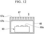
Fig. 12 is used to illustrate a sensor relating to a seventh embodiment of the present invention. - The following describes a sensor relating to a first embodiment of the present invention with reference to the drawings. The constituents common to more than one drawing are denoted by the same reference signs throughout the drawings. It should be noted that the drawings do not necessarily appear to an accurate scale for the sake of convenience of explanation.
-
Fig. 1 is a sectional view showing one example of a mechanism 1 including asensor 5 relating to one embodiment of the present invention. The mechanism 1 is, for example, a movable part such as a robot arm. The mechanism 1 includes aspeed reducer 2, aflange 3 provided on the input side, aservomotor 4, and a device A1 provided on the output side. - The
speed reducer 2 includes acasing 21 mounted to theflange 3, aninput shaft 23 connected to anoutput shaft 22 of theservomotor 4, and anoutput shaft 24 connected to the output-side device A1. Theinput shaft 23 and theoutput shaft 24 are supported to be capable of rotating about an axis AX relative to thecasing 21. The output from theservomotor 4 is input to thespeed reducer 2 via theinput shaft 23, reduced by thespeed reducer 2, and then transmitted to the output-side device A1 via theoutput shaft 24. Thus, the output-side device A1 and theflange 3 are capable of rotating relative to each other. - The
flange 3 is a tubular member and houses therein at least a portion of thespeed reducer 2. Theservomotor 4 is mounted to theflange 3. An opening at one end of theflange 3 in the direction along the axis AX is closed by thespeed reducer 2, and an opening at the other end of theflange 3 is cbsed by theservomotor 4. Thus, theflange 3 has a tightly closed hollow portion (a space S) formed therein. The space S contains therein a lubricating oil, so that theflange 3 also serves as an oil bath. - The
casing 21 of thespeed reducer 2 houses therein a gear mechanism, for example. The space within thecasing 21 communicates with the space S within theflange 3. As thespeed reducer 2 operates, the gear mechanism in thecasing 21 rotates, which subsequently causes the lubricating oil to circulate between the space in thecasing 21 and the space S in theflange 3. As the lubricating oil circulates, a conductive substance such as abrasion powder (conductive abrasion powder) produced in thespeed reducer 2 moves into the space S in theflange 3. - In the space S, a
sensor 5 is installed for sensing the amount of the conductive substance contained in the lubricating oil. Thesensor 5 is fixed onto theflange 3 via, for example, asupport member 25. Thesensor 5 uses a magnet to gather the conductive substance contained in the lubricating oil between paired electrodes and uses a change in electrical resistance between the paired electrodes to sense the amount of the conductive substance in the lubricating oil. Thesensor 5 may be alternatively positioned, for example, inside thecasing 21 but can be at any position within the mechanism 1 as long as the position is within the space containing therein the lubricating oil. - Next, with reference to
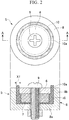
Fig. 2 , a detailed description is given of the structure of thesensor 5.Fig. 2 schematically shows the structure of the sensor relating to the first embodiment of the present invention.Fig. 2 includes a top view of thesensor 5 and a sectional view showing a cross-section along the A-A line in the top view. - As shown in
Fig. 2 , thesensor 5 has a substantially columnar outer shape and includes afirst electrode 6, amagnet 7, asecond electrode 8, afastening member 9, and an attractingportion 10. As shown inFig. 2 , thefirst electrode 6 has a circular shape when seen from the top surface of thesensor 5 and is positioned at the center of thesensor 5. Thesecond electrode 8 is a bottomed tubular member and includes abottom portion 8a extending substantially parallel to thefirst electrode 6 and a wall portion (tubular portion) 8b continuous with thebottom portion 8a and extending substantially perpendicularly to thebottom portion 8a. - The
magnet 7 has a substantially columnar shape and is positioned between thefirst electrode 6 and thebottom portion 8a of thesecond electrode 8. Thefirst electrode 6, themagnet 7, and thebottom portion 8a of thesecond electrode 8 each have therein a through hole, through which the fastening member 9 (a bolt in the illustrated embodiment) is inserted Thefastening member 9 is inserted through the through holes, so that thefirst electrode 6, themagnet 7, and thesecond electrode 8 are fixed to each other. Thefirst electrode 6 and thesecond electrode 8 are fixed while being spaced away from each other. Thefirst electrode 6 and thesecond electrode 8 are made of an electrically conductive magnetic material such as iron, ferrite core and silicon steel Themagnet 7 is, for example, a permanent magnet. Instead of using such a permanent magnet, however, thefirst electrode 6 may serve both as the magnet and as the electrode. - The attracting
portion 10 is provided to fill the space between thefirst electrode 6 and thesecond electrode 8 and interposed between thefirst electrode 6 and thesecond electrode 8. A distance X1 between thefirst electrode 6 and thewall portion 8b of thesecond electrode 8 is larger than the dimension of the conductive substance contained in the lubricating oil For example, the conductive substance has a dimension of approximately 1.0 µm to 100 µm, and the distance X1 is preferably just large enough to prevent a short circuit from occurring due to iron powder produced by initial wear. In the illustrated embodiment, themagnet 7 is in contact with thefirst electrode 6 and surrounded by the attractingportion 10. The attractingportion 10 is made of an insulating non-magnetic material, for example, a resin. Themagnet 7 forms a magnetic flux line between thefirst electrode 6 and thesecond electrode 8. Thus, the conductive substance contained in the lubricating oil is gathered to the vicinity of the attractingportion 10. - The
sensor 5 includes a shortcircuit preventing portion 10a for preventing a short circuit from being caused by a large-diameter conductive piece between thefirst electrode 6 and thesecond electrode 8. Here, the large-diameter conductive piece is, for example, foreign matter such as a cutting chip produced by cutting or other methods of processing performed during the manufacturing process of the mechanism 1 (seeFig. 1 ) and refers to a conductive particle having a dimension larger than the distance X1 between thefirst electrode 6 and thesecond electrode 8. By way of an example, the large-diameter conductive piece has a size of approximately 2 mm to 5 mm. - In the embodiment shown in
Fig. 2 , the shortcircuit preventing potion 10a is a protrusion on the attractingportion 10 and formed integrally with the attractingportion 10. In other words, the shortcircuit preventing portion 10a and the attractingportion 10 form a one-piece structure. Therefore, similarly to the attractingportion 10, the shortcircuit preventing portion 10a is made of an insulating non-magnetic material, for example, a resin. Alternatively, the attractingportion 10 and the shortcircuit preventing portion 10a may be separate members from each other. In the sectional view ofFig. 2 , the shortcircuit preventing portion 10a has a width substantially equal to the distance X1 between thefirst electrode 6 and thewall portion 8b of thesecond electrode 8. When seen from the top surface of thesensor 5, the shortcircuit preventing portion 10a has an annular shape and entirely surrounds thefirst electrode 6. - The
first electrode 6 and thesecond electrode 8 are respectively connected to output lines (not shown) and electrically connected to a sensing unit 50 (seeFig. 1 ) via the output lines. - The
sensing unit 50 is configured to sense a change in electrical resistance between thefirst electrode 6 and thesecond electrode 8. Thesensing unit 50 includes a sensor drive circuit for predicting a failure of the parts constituting the mechanism 1 based on, for example, a change in electrical resistance caused by the gathering of the conductive substance in the vicinity of the attractingportion 10. If the conductive substance contained in the lubricating oil is gathered in the vicinity of the attractingportion 10, this causes a drop in electrical resistance (or a short circuit) between thefirst electrode 6 and thesecond electrode 8 to which voltage is being applied, resulting in a change in output level of the output lines. Thesensing unit 50 senses such a change in electrical resistance, thereby predicting a failure of the parts constituting the mechanism 1. - The drop in electrical resistance may be indicated by an ON signal and an OFF signal corresponding to electrical disconnection and connection. The
sensing unit 50 may sense two states of electrical disconnection and connection (hereinafter, may be referred to as "perform digital sensing"). Thesensing unit 50 may be connected to a higher-level control device (not shown) such as a manipulator in a wired or wireless manner. The higher-level control device may be configured to, upon reception of a signal from thesensing unit 50, issue an alert for demanding maintenance of, for example, thespeed reducer 2 with a predetermined notifying unit (for example, a display or voice output device). - As described above, the
sensor 5 includes the shortcircuit preventing portion 10a for preventing a short circuit between thefirst electrode 6 and thesecond electrode 8 caused by a large-diameter conductive piece having a dimension larger than the distance X1 between thefirst electrode 6 and thesecond electrode 8. The shortcircuit preventing portion 10a is a protrusion on the attractingportion 10. With the protrusion being provided between thefirst electrode 6 and thesecond electrode 8 in this manner, even when a large-diameter conductive piece is attracted to the vicinity of the attractingportion 10, the large-diameter conductive piece is prevented from electrically contacting at least one of thefirst electrode 6 and thesecond electrode 8. Accordingly, a short circuit can be prevented from being caused by the large-diameter conductive piece between thefirst electrode 6 and thesecond electrode 8, resulting in preventing thesensor 5 from operating unexpectedly. - In the
sensor 5, the shortcircuit preventing portion 10a and the attractingportion 10 form a one-piece structure. This reduces the number of parts constituting thesensor 5, so that thesensor 5 can be manufactured easily. - Next, with reference to
Fig. 3 , a description is given of a modification example of the short circuit preventing portion of thesensor 5. As shown inFig. 3 , similarly to the shortcircuit preventing portion 10a, a shortcircuit preventing potion 11 relating to a modification example is a protrusion provided on the attractingportion 10 and formed integrally with the attractingportion 10. Similarly to the shortcircuit preventing portion 10a, the shortcircuit preventing portion 11 is made of, for example, an insulating non-magnetic material such as a resin. When seen from the top surface of thesensor 5, the shortcircuit preventing portion 11 has an annular shape and entirely surrounds thefirst electrode 6. The shortcircuit preventing portion 11 is different from the shortcircuit preventing portion 10a in that the shortcircuit preventing portion 11 has a width smaller than the distance X1 between thefirst electrode 6 and thewall portion 8b of thesecond electrode 8. - As described above, in the
sensor 5 including the shortcircuit preventing portion 11 having a width smaller than the distance X1, electrical contact can be also prevented between a large-diameter conductive piece and at least one of thefirst electrode 6 and thesecond electrode 8. Accordingly, a short circuit is prevented from being caused by the large-diameter conductive piece between thefirst electrode 6 and thesecond electrode 8, resulting in preventing thesensor 5 from operating unexpectedly. - Next, with reference to
Fig. 4 , a description is given of another modification example of a short circuit preventing portion of thesensor 5. As shown inFig. 4 , the short circuit preventing portion of thesensor 5 may be divided into a plurality of portions. In the embodiment shown inFig. 4 , thesensor 5 includes three shortcircuit preventing portions circuit preventing portions portion 10 and formed integrally with the attractingportion 10. Similarly to the attractingportion 10, the shortcircuit preventing portions sensor 5, the shortcircuit preventing portions first electrode 6. - Even if the short circuit preventing portion is divided into a plurality of portions as described above, electrical contact can be prevented between a large-diameter conductive piece and at least one of the
first electrode 6 and thesecond electrode 8 at the positions of the shortcircuit preventing portions first electrode 6 and thesecond electrode 8, resulting in preventing thesensor 5 from operating unexpectedly. - Next, with reference to
Fig. 5 , a description is given of still another modification example of the short circuit preventing portion of thesensor 5. As shown inFig. 5 , the short circuit preventing portion of thesensor 5 may be awire 14 extending in the direction intersecting the direction in which thefirst electrode 6 and thewall portion 8b of thesecond electrode 8 face each other. Thewire 14 is supported by a plurality ofsupport portions 13 and provided on the attractingportion 10 while being spaced away from the attractingportion 10. - In the embodiment shown in
Fig. 5 , thesupport portions 13 are each a stake-shaped member. One of the ends of eachsupport portion 13 is fixedly embedded in the attractingportion 10. The other end of eachsupport portion 13 has therein a through hole, through which thewire 14 is inserted. Thewire 14 is inserted through the through hole, thus being fixed while being spaced away from the attractingportion 10. When seen from the top surface of thesensor 5, thesupport portions 13 are spaced at equal intervals from each other in the circumferential direction of thefirst electrode 6, and thewire 14 entirely surrounds thefirst electrode 6. There are no particular limitations on the material used to form thewire 14. Thewire 14 may be made of a conductive material such as a metal or an insulating material such as a resin. - Even when the short circuit preventing portion is the
wire 14 as described above, thewire 14 can also prevent electrical contact between a large diameter conductive piece and at least one of thefirst electrode 6 and thesecond electrode 8. Accordingly, a short circuit is prevented from occurring between thefirst electrode 6 and thesecond electrode 8, resulting in preventing thesensor 5 from operating unexpectedly. - Next, with reference to
Fig. 6 , a description is given of yet another modification example of the short circuit preventing portion of thesensor 5. As shown inFig. 6 , a shortcircuit preventing portion 15 relating to the modification example may be an insulating protrusion provided on at least one of thefirst electrode 6 and thesecond electrode 8. In the illustrated embodiment, the shortcircuit preventing portion 15 is provided on thewall portion 8b of thesecond electrode 8 to extend along the inner edge of thewall portion 8b, where thewall portion 8b is in contact with the attractingportion 10. The shortcircuit preventing portion 15 may be provided on thefirst electrode 6 or on both of thefirst electrode 6 and thesecond electrode 8. - Even when the short
circuit preventing portion 15 is provided on at least one of the first andsecond electrodes circuit preventing portion 15 prevents electrical contact between a large diameter conductive piece and at least one of thefirst electrode 6 and thesecond electrode 8, similarly to the shortcircuit preventing portion 10a. Accordingly, a short circuit is prevented from occurring between thefirst electrode 6 and thesecond electrode 8, resulting in preventing thesensor 5 from operating unexpectedly. - The following describes a sensor relating to a second embodiment of the present invention with reference to the drawings.
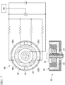
Fig. 7 is used to illustrate the sensor relating to the second embodiment. Thesensor 30 relating to the second embodiment is configured to sense the amount of a conductive substance contained in a lubricating oil, similarly to thesensor 5 relating to the above-described first embodiment. - The
sensor 30 has a substantially columnar outer shape and includes a plurality of detecting units and asensing unit 50 configured to output a signal when the detecting units experience a change in electrical resistance. More specifically, thesensor 30 includes acenter electrode 31, a plurality ofouter electrodes 32, an attractingportion 33 disposed between thecenter electrode 31 and theouter electrodes 32, and amagnet 34. Theouter electrodes 32 are insulated from each other. Each of the detecting units is constituted by a pair of electrodes and the attractingportion 33 disposed between the electrodes. The pair of electrodes includes thecenter electrode 31 and one of theouter electrodes 32. - In the illustrated embodiment, the
sensor 30 includes fourouter electrodes outer electrodes 32 and the number of the detecting units. Themagnet 34 of thesensor 30 forms a magnetic flux line between the paired electrodes, so that a conductive substance contained in a lubricating oil is attracted to the attractingportion 33. When the conductive substance is gathered in the vicinity of the attractingportion 33 in this manner, the detecting units experience a change in electrical resistance. While no conductive particles are attracted, the detecting units exhibit the same electrical resistance. - The
center electrode 31 and theouter electrodes 32 are respectively connected to output lines, and each detecting unit is electrically connected to thesensing unit 50 via a corresponding one of the output lines. In this embodiment, the detecting units are connected in parallel to each other, and voltage is applied by the same voltage source between thecenter electrode 31 and each of theouter electrodes 32. Thesensing unit 50 outputs a signal if a designated number of detecting units experience a change in electrical resistance. For example, thesensing unit 50 may be configured to output a signal to a higher-level control device such as a manipulator when two or more of the detecting units experience a drop in electrical resistance or when all of the detecting units experience a drop in electrical resistance. - As described above, the
sensor 30 includes the plurality of detecting units, and thesensing unit 50 outputs a signal when a designated number of detecting units experience a drop in electrical resistance. In this way, thesensing unit 50 can be configured to output no signal when just one of the detecting units experiences a change in electrical resistance caused by a large-diameter conductive piece. This can prevent the sensor from operating unexpectedly due to a large-diameter conductive piece. Furthermore, in thesensor 30, thesensing unit 50 can be configured to output a signal under a designated condition. Therefore, thesingle sensor 30 can be configured to output a signal in a timely and optimal manner for individual users, who have different requests for failure prediction timing. - While no conductive particles are attracted, the detecting units are equal in electrical resistance. This can lower the voltage to be applied to the
sensor 30. - The detecting units are connected in parallel to each other. This can lower the voltage applied between the paired electrodes in each detecting unit.
- The following describes a sensor relating to a third embodiment of the present invention with reference to the drawings.
Fig. 8 is a sectional view showing the sensor relating to the present embodiment. The present embodiment is different from the above-described embodiments in terms of the attracting portion. Note thatFig. 8 does not show all of the constituents. - As shown in
Fig. 8 , asensor 60 relating to the present embodiment has a substantially columnar outer shape and includes a first electrode (inner electrode) 61, amagnet 64, a second electrode (outer electrode) 62, a fastening member (fastening portion) 69, an attracting portion (insulator) 63 and acasing 65. When seen from the top surface of thesensor 60, the first electrode (inner electrode) 61 has a circular shape and is positioned at the center of thesensor 60. The second electrode (outer electrode) 62 is a bottomed tubular member and has abottom portion 62a extending substantially parallel to the first electrode (inner electrode) 61 and a wall portion (tubular portion) 62b continuous with thebottom portion 62a and extending substantially perpendicularly to thebottom portion 62a. The first electrode (inner electrode) 61 is positioned at the opening of the second electrode (outer electrode) 62. - The
magnet 64 has a substantially columnar (substantially disk-shaped) shape and is positioned between the first electrode (inner electrode) 61 and thebottom portion 62a of the second electrode (outer electrode) 62. The first electrode (inner electrode) 61, themagnet 64, and thebottom portion 62a of the second electrode (outer electrode) 62 each have therein a through hole, through which the fastening member (fastening portion) 69 (a bolt in the illustrated embodiment) is inserted The fastening member (fastening portion) 69 is inserted through the through hole, so that the first electrode (inner electrode) 61, themagnet 64, and the second electrode (outer electrode) 62 are fixed to each other. Themagnet 64 is smaller in outer diameter than the second electrode (outer electrode) 62. - The first electrode (inner electrode) 61 and the second electrode (outer electrode) 62 are fixed while being spaced away from each other. The first electrode (inner electrode) 61 and the second electrode (outer electrode) 62 are, for example, made of an electrically conductive magnetic material such as iron, ferrite core, or silicon steel The
magnet 64 is, for example, a permanent magnet. Instead of using such a permanent magnet, however, the first electrode (inner electrode) 61 may serve both as the magnet and as the electrode. - The attracting portion (insulator) 63 fills the space between the first electrode (inner electrode) 61 and the second electrode (outer electrode) 62 and is interposed between the first electrode (inner electrode) 61 and the second electrode (outer electrode) 62. The attracting portion (insulator) 63 has a
bottom portion 63a extending along thebottom portion 62a of the second electrode (outer electrode) 62 and atubular portion 63b extending along the wall portion (tubular portion) 62b of the second electrode (outer electrode) 62. Thebottom portion 63a and thetubular portion 63b are separate members. Thebottom portion 63a is shaped like a sheet. - The
bottom portion 63a of the attracting portion (insulator) 63 can be, for example, insulating paper having a thickness of 0.05 to 1 mm. Thebottom portion 63a of the attracting portion (insulator) 63 can be circular paper having an outer diameter substantially the same as the inner diameter of thetubular portion 63b. Alternatively, thebottom portion 63a can be circular paper having an outer diameter larger than the inner diameter of thetubular portion 63b. In this case, thebottom portion 63a can be circular paper having an outer diameter smaller than the outer diameter of thetubular portion 63b. Alternatively, thebottom portion 63a can be circular paper having an outer diameter same as the outer diameter of thetubular portion 63b. - On the inner surface of the
tubular portion 63b of the attracting portion (insulator) 63, astep 63c is formed In thetubular portion 63b of the attracting portion (insulator) 63, the portion on the first electrode (inner electrode) 61 side with respect to thestep 63c has an inner diameter equal to the outer diameter of the first electrode (inner electrode) 61. In thetubular portion 63b of the attracting portion (insulator) 63, the portion on themagnet 64 side with respect to thestep 63c has an inner diameter equal to the outer diameter of themagnet 64. - The thickness of the end of the
tubular portion 63b of the attracting portion (insulator) 63, in other words, the distance X1 between the first electrode (inner electrode) 61 and thewall portion 62b of the second electrode (outer electrode) 62 is larger than the dimension of the conductive substance contained in the lubricating oil. For example, the conductive substance has a dimension of approximately 1.0 µm to 100 µm, and the distance X1 is preferably just large enough to prevent a short circuit from occurring due to iron powder produced by initial wear. In the illustrated embodiment, themagnet 64 is in contact with the first electrode (inner electrode) 61 and surrounded by the attracting portion (insulator) 63. - The attracting portion (insulator) 63 is made of, for example, an insulating non-magnetic material such as a resin. The
magnet 64 forms a magnetic flux line between the first electrode (inner electrode) 61 and the second electrode (outer electrode) 62. Thus, the conductive substance contained in the lubricating oil is gathered to the vicinity of the attracting portion (insulator) 63. Note that the term "detection region" denotes the region within which the lubricating oil circulates. - In the
sensor 60 relating to the present embodiment, asensing plane 60a denotes the plane connecting the end of the second electrode (outer electrode) 62 and the surface of the first electrode (inner electrode) 61, which are substantially flush with each other. In other words, on thesensing plane 60a, conductive abrasion powder is attracted between the first electrode (inner electrode) 61 and the second electrode (outer electrode) 62 by the magnetic flux line, so that the first electrode (inner electrode) 61 and the second electrode (outer electrode) 62 are electrically connected This causes a change in resistance between the first electrode (inner electrode) 61 and the second electrode (outer electrode) 62, which is to be detected Note that the first electrode (inner electrode) 61 may not need to be flush with the opening of the second electrode (outer electrode) 62. - As the creepage distance between the first electrode (inner electrode) 61 and the second electrode (outer electrode) 62 increases, the amount of conductive abrasion powder required to be attracted to lower the resistance to a threshold value or to cause a short circuit between the first electrode (inner electrode) 61 and the second electrode (outer electrode) 62 increases. As the creepage distance between the first electrode (inner electrode) 61 and the second electrode (outer electrode) 62 decreases, the amount of conductive abrasion powder required to be attracted to lower the resistance to a threshold value or to cause a short circuit between the first electrode (inner electrode) 61 and the second electrode (outer electrode) 62 decreases.
- The
sensor 60 relating to the present embodiment has a sensitivity adjusting unit for adjusting the attraction of the conductive abrasion powder to change the sensitivity. In the present embodiment, the sensitivity adjusting unit is the attracting portion (insulator) 63. More specifically, in the present embodiment, the sensitivity adjusting unit is thetubular portion 63b of the attracting portion (insulator) 63. - The attracting portion (insulator) 63 of the present embodiment is capable of adjusting the creepage distance between the first electrode (inner electrode) 61 and the second electrode (outer electrode) 62 to adjust the amount of conductive abrasion powder to be attracted by the attracting portion (insulator) 63. Specifically, a group of attracting portions (insulators) 63 are provided that have
tubular portions 63b with different protruding heights with respect to thesensing plane 60a, as shown inFig. 8 . In thesensor 60A shown inFig. 8 , thesensing plane 60a is at the same level as the end of thetubular portion 63b of an attracting portion (insulator) 63A or at a height HA. In other words, thesensing plane 60a is flush with thetubular portion 63b of the attracting portion (insulator) 63A. - In the
sensor 60B shown inFig. 8 , the end of thetubular portion 63b of an attracting portion (insulator) 63B is higher than thesensing plane 60a by a height HB, in other words, thetubular portion 63b of the attracting portion (insulator) 63B protrudes with respect to thesensing plane 60a by the height HB. In thesensor 60C shown inFig. 8 , the end of thetubular portion 63b of an attracting portion (insulator) 63C is higher than thesensing plane 60a by a height HC, in other words, thetubular portion 63b of the attracting portion (insulator) 63C protrudes with respect to thesensing plane 60a by the height HC. In thesensor 60D shown inFig. 8 , the end of thetubular portion 63b of an attracting portion (insulator) 63D is higher than thesensing plane 60a by a height HD, in other words, thetubular portion 63b of the attracting portion (insulator) 63D protrudes with respect to thesensing plane 60a by the height HD. - Here, the heights HA, HB, HC and HD are related to each other as follows:
HA (=0) < HB < HC < HD. - The
sensor 60 relating to the present embodiment has a group of attracting portions (insulators) 63 that are different in the value of thetubular portion 63b as described above. Thesensor 60 relating to the present embodiment can be assembled with a selected one of the attracting portions. This means that the group of attracting portions (insulators) 63 that are different in the height (axial dimension) of thetubular portion 63b serves as the sensitivity adjusting unit. In this way, the creepage distance between the first electrode (inner electrode) 61 and the second electrode (outer electrode) 62 can be selected from among a plurality of values by making a selection in the sensitivity adjusting unit. - A reference creepage distance denotes the creepage distance in the
sensor 60A shown inFig. 8 between the first electrode (inner electrode) 61 and the second electrode (outer electrode) 62, which is defined by the end of thetubular portion 63b of the attracting portion (insulator) 63A. - In the
sensor 60B shown inFig. 8 , the creepage distance between the first electrode (inner electrode) 61 and the second electrode (outer electrode) 62, which is defined by the end of thetubular portion 63b of the attracting portion (insulator) 63B, is longer than the reference creepage distance. Accordingly, a larger amount of conductive abrasion powder can be attracted before the resistance between the first electrode (inner electrode) 61 and the second electrode (outer electrode) 62 drops to a threshold value or before a short circuit occurs. In this way, for example, even when thespeed reducer 2 has a large size and thus produces an increased amount of initial abrasion powder, thesensor 60B can reliably sense the failure of thespeed reducer 2 without being affected by the increased amount of initial abrasion powder. - In the
sensor 60C shown inFig. 8 , the creepage distance between the first electrode (inner electrode) 61 and the second electrode (outer electrode) 62, which is defined by the end of thetubular portion 63b of the attracting portion (insulator) 63C, is longer than in thesensor 60B. Accordingly, a further larger amount of conductive abrasion powder can be attracted before the resistance between the first electrode (inner electrode) 61 and the second electrode (outer electrode) 62 drops to a threshold value or before a short circuit occurs. In this way, even when thespeed reducer 2 has a further larger size and thus produces an increased amount of initial abrasion powder, thesensor 60C can reliably sense the failure of thespeed reducer 2 without being affected by the increased amount of initial abrasion powder. - In the
sensor 60D shown inFig. 8 , the creepage distance between the first electrode (inner electrode) 61 and the second electrode (outer electrode) 62, which is defined by the end of thetubular portion 63b of the attracting portion (insulator) 63D, is longer than in thesensor 60C. Accordingly, a further larger amount of conductive abrasion powder can be attracted before the resistance between the first electrode (inner electrode) 61 and the second electrode (outer electrode) 62 drops to a threshold value or before a short circuit occurs. In this way, even when thespeed reducer 2 has a further larger size and thus produces an increased amount of initial abrasion powder, thesensor 60D can reliably sense the failure of thespeed reducer 2 without being affected by the increased amount of initial abrasion powder. - As described above, the
sensor 60 can reliably sense the failure of thespeed reducer 2 by selecting an appropriate one of the attracting portions (insulators) 63 without the need of increasing the size of thesensor 60 and also without affecting the other constituents. In other words, thesensor 60 can achieve different levels of sensitivity by replacing only the attracting portion (insulator) 63 while using the center electrode (inner electrode) 61, the external electrode (outer electrode) 62, themagnet 64, thecasing 65 and the fastening member (fastening portion) 69 in common. - In the present embodiment described above, four different attracting portions (insulators) 63 are employed as the sensitivity adjusting unit, but the present invention is not limited to such and the number can be determined appropriately.
- The
sensor 60 relating to the present embodiment can be assembled in the following manner. - To start with, the external electrode (outer electrode) 62 is placed within the
casing 65. Subsequently, thebottom portion 63a of the attracting portion (insulator) 63 is positioned on thebottom portion 62a of the external electrode (outer electrode) 62. Following this, thetubular portion 63b of the attracting portion (insulator) 63 having a selected height is inserted into the external electrode (outer electrode) 62. Subsequently, themagnet 64 is inserted into thetubular portion 63b, and the center electrode (inner electrode) 61 is further inserted At this stage, the fastening member (fastening portion) 69 is inserted and fixedly fastened In this way, thesensor 60 is assembled - Having the sensitivity adjusting unit, the
sensor 60 relating to the present embodiment is capable of setting the sensitivity at a predetermined level Specifically, when a large amount of conductive abrasion powder is expected to be produced, the sensitivity adjusting unit can be selected such that a larger creepage distance to attract the abrasion powder can be obtained between theelectrode 61 and theelectrode 62 to set the sensitivity of thesensor 60 at a predetermined level In addition, when a small amount of conductive abrasion powder is expected to be produced, the sensitivity adjusting unit can be selected such that a smaller creepage distance to attract the abrasion powder can be obtained between theelectrode 61 and theelectrode 62 to set the sensitivity of thesensor 60 at a predetermined level In this way, thesensor 60 can reliably sense a failure of thespeed reducer 2 without being affected by the increased amount of initial abrasion powder produced by thespeed reducer 2. - Speed reducers of different models (sizes) may produce different amounts of iron powder (abrasion powder) during the initial wear period. In the case of large speed reducers, a large amount of initial abrasion iron powder is produced, and the initial abrasion iron powder may fill the electrical gap in the sensor between the
electrodes sensor 60 relating to the present embodiment has a sensitivity adjusting unit, which includes attracting portions (insulators) 63 with different heights. This configuration produces the same effects as the enlargement of the sensor in the diameter direction and thus allows thesensor 60 to maintain the size. - The following describes a sensor relating to a fourth embodiment of the present invention with reference to the drawings.
Fig. 9 is a top view showing the sensor relating to the present embodiment. The present embodiment is different from the above-described third embodiment in terms of the attracting portion and outer electrode.Fig. 9 does not show all of the constituents. - As shown in
Fig. 9 , thesensor 60 relating to the present embodiment has a substantially columnar outer shape and includes a first electrode (inner electrode) 61, amagnet 64, a second electrode (outer electrode) 62, a fastening member (fastening portion) 69, an attracting portion (insulator) 63 and acasing 65. When seen from the top surface of thesensor 60, the first electrode (inner electrode) 61 has a circular shape and is positioned at the center of thesensor 60. The second electrode (outer electrode) 62 is a bottomed tubular member and has abottom portion 62a extending substantially parallel to the first electrode (inner electrode) 61 and a wall portion (tubular portion) 62b continuous with thebottom portion 62a and extending substantially perpendicularly to thebottom portion 62a. - The
magnet 64 has a substantially columnar (substantially disk-shaped) shape and is positioned between the first electrode (inner electrode) 61 and thebottom portion 62a of the second electrode (outer electrode) 62. The first electrode (inner electrode) 61, themagnet 64, and thebottom portion 62a of the second electrode (outer electrode) 62 each have therein a through hole, through which the fastening member (fastening portion) 69 (a bolt in the illustrated embodiment) is inserted The fastening member (fastening portion) 69 is inserted through the through hole, so that the first electrode (inner electrode) 61, themagnet 64, and the second electrode (outer electrode) 62 are fixed to each other. Themagnet 64 is smaller in outer diameter than the second electrode (outer electrode) 62. - The first electrode (inner electrode) 61 and the second electrode (outer electrode) 62 are fixed while being spaced away from each other. The first electrode (inner electrode) 61 and the second electrode (outer electrode) 62 are, for example, made of an electrically conductive magnetic material such as iron, ferrite core, or silicon steel The
magnet 64 is, for example, a permanent magnet. Instead of using such a permanent magnet, however, the first electrode (inner electrode) 61 may serve both as the magnet and as the electrode. - The attracting portion (insulator) 63 fills the space between the first electrode (inner electrode) 61 and the second electrode (outer electrode) 62 and is interposed between the first electrode (inner electrode) 61 and the second electrode (outer electrode) 62. The attracting portion (insulator) 63 has a
bottom portion 63a extending along thebottom portion 62a of the second electrode (outer electrode) 62 and atubular portion 63b extending along the wall portion (tubular portion) 62b of the second electrode (outer electrode) 62. Thebottom portion 63a and thetubular portion 63b are separate members. Thebottom portion 63a is shaped like a sheet. - The
bottom portion 63a of the attracting portion (insulator) 63 can be, for example, insulating paper having a thickness of 0.05 to 1 mm. Thebottom portion 63a of the attracting portion (insulator) 63 can be circular paper having an outer diameter substantially the same as the inner diameter of thetubular portion 63b. Alternatively, thebottom portion 63a can be circular paper having an outer diameter larger than the inner diameter of thetubular portion 63b. In this case, thebottom portion 63a can be circular paper having an outer diameter smaller than the outer diameter of thetubular portion 63b. Alternatively, thebottom portion 63a can be circular paper having an outer diameter same as the outer diameter of thetubular portion 63b. - On the inner surface of the
tubular portion 63b of the attracting portion (insulator) 63, astep 63c is formed. In thetubular portion 63b of the attracting portion (insulator) 63, the portion on the first electrode (inner electrode) 61 side with respect to thestep 63c has an inner diameter equal to the outer diameter of the first electrode (inner electrode) 61. In thetubular portion 63b of the attracting portion (insulator) 63, the portion on themagnet 64 side with respect to thestep 63c has an inner diameter equal to the outer diameter of themagnet 64. - The thickness of the end of the
tubular portion 63b of the attracting portion (insulator) 63, in other words, the distance X1 between the first electrode (inner electrode) 61 and thewall portion 62b of the second electrode (outer electrode) 62 is larger than the dimension of the conductive substance contained in the lubricating oil. For example, the conductive substance has a dimension of approximately 1.0 µm to 100 µm, and the distance X1 is preferably just large enough to prevent a short circuit from occurring due to iron powder produced by initial wear. In the illustrated embodiment, themagnet 64 is in contact with the first electrode (inner electrode) 61 and surrounded by the attracting portion (insulator) 63. - The attracting portion (insulator) 63 is, for example, made of an insulating non-magnetic material such as a resin. The
magnet 64 forms a magnetic flux line between the first electrode (inner electrode) 61 and the second electrode (outer electrode) 62. In this way, the conductive substance contained in the lubricating oil is gathered to the vicinity of the attracting portion (insulator) 63. - In the
sensor 60 relating to the present embodiment, asensing plane 60a denotes the plane connecting the end of the second electrode (outer electrode) 62 and the surface of the first electrode (inner electrode) 61, which are substantially flush with each other. In other words, on thesensing plane 60a, conductive abrasion powder is attracted between the first electrode (inner electrode) 61 and the second electrode (outer electrode) 62 by the magnetic flux line, so that the first electrode (inner electrode) 61 and the second electrode (outer electrode) 62 are electrically connected This causes a change in resistance between the first electrode (inner electrode) 61 and the second electrode (outer electrode) 62, which is to be detected - As the creepage distance between the first electrode (inner electrode) 61 and the second electrode (outer electrode) 62 increases, the amount of conductive abrasion powder required to be attracted to lower the resistance to a threshold value or to cause a short circuit between the first electrode (inner electrode) 61 and the second electrode (outer electrode) 62 increases. As the creepage distance between the first electrode (inner electrode) 61 and the second electrode (outer electrode) 62 decreases, the amount of conductive abrasion powder required to be attracted to lower the resistance to a threshold value or to cause a short circuit between the first electrode (inner electrode) 61 and the second electrode (outer electrode) 62 decreases.
- The
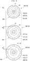
sensor 60 relating to the present embodiment has a sensitivity adjusting unit for adjusting the attraction of the conductive abrasion powder to change the sensitivity. In the present embodiment, the sensitivity adjusting unit is the attracting portion (insulator) 63. More specifically, in the present embodiment, the sensitivity adjusting unit is thetubular portion 63b of the attracting portion (insulator) 63, the external electrode (outer electrode) 62 and thecasing 65. - The attracting portion (insulator) 63 of the present embodiment is capable of adjusting the creepage distance between the first electrode (inner electrode) 61 and the second electrode (outer electrode) 62 considering the large-diameter conductive chip to adjust the amount of the conductive abrasion powder to be attracted by the attracting portion (insulator) 63. Specifically, as shown in
Fig. 9 , a group of attracting portions (insulators) 63 are provided that are different in the radial thickness of thetubular portion 63b. Asensor 60E shown inFig. 9 has an attracting portion - (insulator) 63E, whose
tubular portion 63b has an end with a thickness X1 on thesensing plane 60a, in other words, which provides a distance X1 on thesensing plane 60a between the first electrode (inner electrode) 61 and thewall portion 62b of the second electrode (outer electrode) 62. Thesensor 60E includes an external electrode (outer electrode) 62E and acasing 65E having a radial dimension corresponding to the attracting portion (insulator) 63E. - A
sensor 60F shown inFig. 9 has an attracting portion (insulator) 63F, whosetubular portion 63b has an end with a thickness X2 on thesensing plane 60a, in other words, which provides a distance X2 on thesensing plane 60a between the first electrode (inner electrode) 61 and thewall portion 62b of the second electrode (outer electrode) 62. Thesensor 60F includes an external electrode (outer electrode) 62F and acasing 65F having a radial dimension corresponding to the attracting portion (insulator) 63F. Asensor 60G shown inFig. 9 has an attracting portion (insulator) 63G, whosetubular portion 63b has an end with a thickness X3 on thesensing plane 60a, in other words, which provides a distance X3 on thesensing plane 60a between the first electrode (inner electrode) 61 and thewall portion 62b of the second electrode (outer electrode) 62. Thesensor 60G includes an external electrode (outer electrode) 62G and acasing 65G having a radial dimension corresponding to the attracting portion (insulator) 63G. - Here, the thicknesses X1, X2 and X3 are related to each other as follows:

- The
sensor 60 relating to the present embodiment has a group of attracting portions (insulators) 63 that are different in the value of thetubular portion 63b as described above. Thesensor 60 relating to the present embodiment can be assembled with a selected one of the attracting portions. This means that the group of attracting portions (insulators) 63 that are different in the thickness (radial dimension) of thetubular portion 63b serves as the sensitivity adjusting unit. In this way, the creepage distance between the first electrode (inner electrode) 61 and the second electrode (outer electrode) 62 can be selected from among a plurality of values by making a selection in the sensitivity adjusting unit. - A reference creepage distance denotes the creepage distance in the
sensor 60E shown inFig. 9 between the first electrode (inner electrode) 61 and the second electrode (outer electrode) 62E, which is defined by the end of thetubular portion 63b of the attracting portion (insulator) 63E. - In the
sensor 60F shown inFig. 9 , the creepage distance between the first electrode (inner electrode) 61 and the second electrode (outer electrode) 62F, which is defined by the end of thetubular portion 63b of the attracting portion (insulator) 63 F, is longer than the reference creepage distance. Accordingly, a larger amount of conductive abrasion powder can be attracted before the resistance between the first electrode (inner electrode) 61 and the second electrode (outer electrode) 62F drops to a threshold value or to cause a short circuit. In this way, for example, even when thespeed reducer 2 has a large size and thus produces an increased amount of initial abrasion powder, thesensor 60F can reliably sense the failure of thespeed reducer 2 without being affected by the increased amount of initial abrasion powder. - In the
sensor 60G shown inFig. 9 , the creepage distance between the first electrode (inner electrode) 61 and the second electrode (outer electrode) 62G, which is defined by the end of thetubular portion 63b of the attracting portion (insulator) 63G, is longer than in thesensor 60F. Accordingly, a further larger amount of conductive abrasion powder can be attracted before the resistance between the first electrode (inner electrode) 61 and the second electrode (outer electrode) 62G drops to a threshold value or to cause a short circuit. In this way, even when thespeed reducer 2 has a further larger size and thus produces an increased amount of initial abrasion powder, thesensor 60G can reliably sense the failure of thespeed reducer 2 without being affected by the increased amount of initial abrasion powder. - As described above, the
sensor 60 can reliably sense the failure of thespeed reducer 2 by selecting an appropriate one of the attracting portions (insulators) 63 without the need of increasing the axial size of thesensor 60 and also without affecting the center electrode (inner electrode) 61, themagnet 64 and the fastening member (fastening portion) 69. In other words, thesensor 60 can achieve different levels of sensitivity by replacing the attracting portion (insulator) 63, the external electrode (outer electrode) 62 and thecasing 65 while using the center electrode (inner electrode) 61, themagnet 64 and the fastening member (fastening portion) 69 in common. - In the present embodiment described above, three different attracting portions (insulators) 63 are employed as the sensitivity adjusting unit, but the present invention is not limited to such and the number can be determined appropriately.
- The
sensor 60 relating to the present embodiment can be assembled in the following manner. - To start with, the external electrode (outer electrode) 62 is placed within the
casing 65 having a selected radial dimension. Subsequently, thebottom portion 63a of the attracting portion (insulator) 63 having a corresponding radial dimension is placed on thebottom portion 62a of the external electrode (outer electrode) 62. Following this, thetubular portion 63b of the attracting portion (insulator) 63 having a selected radial dimension is inserted into the external electrode (outer electrode) 62. Subsequently, themagnet 64 is inserted into thetubular portion 63b, and the center electrode (inner electrode) 61 is further inserted At this stage, the fastening member (fastening portion) 69 is inserted and fixedly fastened, so that thesensor 60 is assembled. Here, the set of thecasing 65, external electrode (outer electrode) 62, attracting portion (insulator) 63 having the selected radial dimension can be alternatively assembled together in advance. - Having the sensitivity adjusting unit, the
sensor 60 relating to the present embodiment is capable of setting the sensitivity at a predetermined level. Specifically, when a large amount of conductive abrasion powder is expected to be produced, the sensitivity adjusting unit can be selected such that a larger creepage distance to attract the abrasion powder can be obtained between theelectrode 61 and theelectrode 62 to set the sensitivity of thesensor 60 at a predetermined level In addition, when a small amount of conductive abrasion powder is expected to be produced, the sensitivity adjusting unit can be selected such that a smaller creepage distance to attract the abrasion powder can be obtained between theelectrode 61 and theelectrode 62 to set the sensitivity of thesensor 60 at a predetermined level In this way, thesensor 60 can reliably sense the failure of thespeed reducer 2 without being affected by the increased amount of initial abrasion powder produced by thespeed reducer 2. - The following describes a sensor relating to a fifth embodiment of the present invention with reference to the drawings.
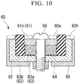
Fig. 10 is a sectional view showing the sensor relating to the present embodiment. The present embodiment is different from the above-described third and fourth embodiments in terms of the electrodes.Fig. 10 does not show all of the constituents. - The
sensor 60 relating to the present embodiment is configured in substantially the same manner as thesensors 60 relating to the third and fourth embodiments, as shown inFig. 10 . Thesensor 60 relating to the present embodiment has a sensitivity adjusting unit for adjusting attraction of conductive abrasion powder to change the sensitivity. - In the present embodiment, the sensitivity adjusting unit is the first electrode (inner electrode) 61 and the second electrode (outer electrode) 62. The first electrode (inner electrode) 61 of the present embodiment has a
surface treatment layer 61h formed thereon. The second electrode (outer electrode) 62 of the present embodiment has asurface treatment layer 62h formed thereon. - The surface treatment layers 61h and 62h both exhibit excellent slippery and non-adhesive properties and additionally have electrical conductivity, smoothness, lubricity and low adhesiveness. The surface treatment layers 61h and 62h can be formed of, for example, fluororesin electroless nickel composite plating or the like. Here, the fluororesin can be polytetrafluoroethylene particles or the like.
- Here, sludge may possibly reduce the amount of abrasion powder to be attracted by the first electrode (inner electrode) 61 and the second electrode (outer electrode) 62. The surface treatment layers 61h and 62h can prevent the sludge from adhering to the first electrode (inner electrode) 61, the second electrode (outer electrode) 62, and the
sensing plane 60a and resultantly from reducing the amount of abrasion powder to be attracted between the first electrode (inner electrode) 61 and the second electrode (outer electrode) 62. In this way, the sensitivity of thesensor 60 can be set at a predetermined level InFig. 10 , the dotted lines indicate the adhering sludge. - Without the surface treatment layers 61h and 62h, the sludge produced by the lubricant accumulates on the electrodes of the sensor to form an insulating coating, which may possibly cause the
sensor 60 to malfunction. To address this issue, the present embodiment includes the surface treatment layers 61h and 62h. The surface treatment layers 61h and 62h can improve the slipperiness, thereby achieving excellent flow of the lubricant. As a result, the sludge can be prevented from accumulating and thesensor 60 can be thus expected to predict a failure in a stable manner. - The following describes a sensor relating to a sixth embodiment of the present invention with reference to the drawings.
Fig. 11 is used to illustrate the sensor relating to the sixth embodiment. Thesensor 60 relating to the sixth embodiment is configured to sense the amount of conductive substance contained in a lubricating oil, similarly to thesensor 30 relating to the above-described second embodiment. - The
sensor 60 has a substantially columnar outer shape and includes a plurality of detecting units and asensing unit 70 configured to output a signal when the detecting units experience a change in electrical resistance and to prevent electrical leakage. More specifically, thesensor 60 includes acenter electrode 61, a plurality ofouter electrodes 62, an attractingportion 63 disposed between thecenter electrode 61 and theouter electrode 62, and amagnet 64. Theouter electrodes 62 are insulated from each other. Each of the detecting units is constituted by a pair of electrodes and the attractingportion 63 disposed between the paired electrodes. The pair of electrodes includes thecenter electrode 61 and one of theouter electrodes 62. - In the illustrated embodiment, the
sensor 60 includes fourouter electrodes outer electrodes 62 and the number of the detecting units. Since themagnet 64 of thesensor 60 forms a magnetic flux line between the paired electrodes, the conductive substance contained in the lubricating oil is attracted by the attractingportion 63. When the conductive substance is gathered in the vicinity of the attractingportion 63 in this manner, the detecting units experience a change in electrical resistance. While no conductive abrasion particles are attracted, the detecting units are equal in electrical resistance. - The
center electrode 61 and theouter electrodes 62 are respectively connected to output lines, and each detecting unit is electrically connected to thesensing unit 70 via a corresponding one of the output lines. - In this embodiment, the detecting units are connected in parallel to each other, and voltage is applied between the
center electrode 61 and each of theouter electrodes 62 by the same voltage source. Thesensing unit 70 outputs a signal when a designated number of the detecting units experience a change in electrical resistance. For example, thesensing unit 70 may be configured to output a signal to a higher-level control device such as a manipulator when two or more of the detecting units experience a drop in electrical resistance, or configured to output a signal when all of the detecting units experience a drop in electrical resistance. - Alternatively, the
sensing unit 70 selects a designated one of the detection units in a particular order and outputs a signal when the selected detecting unit experiences a change in electrical resistance. In addition, thesensing unit 70 is configured to output a signal when the detecting units experience a drop in electrical resistance as described above and to, subsequently, turn off the sensing power fed to thesensor 60. - Specifically, the
sensing unit 70 is configured to output a signal to put on a failure display when the detecting units experience a drop in electrical resistance as described above and to, subsequently, disconnect aswitch 71 in order to turn off the sensing power fed to thesensor 60. In other words, the power is no longer fed once thesensor 60 senses an increase in the amount of iron powder (a drop in resistance of the gap) and thus determines that thespeed reducer 2 is malfunctioning. - This can prevent electrical leakage and shock even if the abrasion powder keeps accumulating to cause the
sensor 60 to come into contact with thespeed reducer 2 or mechanism 1. If thespeed reducer 2 is continuously used even after thesensor 60 reports the failure of thespeed reducer 2, the iron powder is continuously produced in thespeed reducer 2 as thespeed reducer 2 operates and the conductive abrasion powder resultantly keeps accumulating on thesensor 60. As the iron powder accumulates, the dimensions of thesensor 60 increase. The abrasion powder resultantly causes thesensor 60 to come into contact with and establish electrical connection with the parts of the mechanism 1, which may disadvantageously result in electrical leakage and shock. The present embodiment can prevent this case. - The following describes a sensor relating to a seventh embodiment of the present invention with reference to the drawings.
Fig. 12 is used to illustrate the sensor relating to the seventh embodiment. Thesensor 60 relating to the seventh embodiment is configured to sense the amount of a conductive substance contained in a lubricating oil, similarly to thesensors Fig. 12 , acover 66 is provided to cover thesensor 60 in the space S. Thecover 66 houses thesensor 60 therein and has a large number of throughholes 67 positioned to face thesensing plane 60a of thesensor 60. - The through holes 67 have a larger diameter at an
external opening 67a thereof, which faces the space S external to thecover 66, than at aninternal opening 67b thereof, which faces thesensor 60 arranged within thecover 66. When entering the inside of thecover 66 from the space S through the throughholes 67, the conductive abrasion powder passes through the throughholes 67 having the decreasing diameter and then reaches thesensor 60. Thecover 66 is arranged such that theinternal opening 67b of the throughholes 67 is spaced away from thesensing plane 60a of thesensor 60. The inside of thecover 66 is tightly sealed, except for the through holes 67. - With such configurations, the
sensor 60 can be protected by thecover 66 even if the mechanism 1 and thespeed reducer 2 violently operate and the lubricant flows violently. This can prevent the conductive abrasion powder from moving back into the external space S after entering the inside of thecover 66. As a result, thesensor 60 can keep the accurate amount of the attracted conductive abrasion powder and reliably predict a failure. In addition, since the conductive abrasion powder is prevented from leaving the space inside thecover 66 after entering the inside of thecover 66, the influence on the mechanism 1 and thespeed reducer 2 can be reduced. Thecover 66 can have an inner diameter substantially equal to the outer diameter of thesensor 60, when seen in the axial direction of thesensor 60. - Furthermore, according to the present embodiment, the
cover 66 can prevent a large amount of abrasion powder from being attracted by thesensor 60 at once during the initial stage of the operation of thespeed reducer 2, in which a small amount of abrasion powder is produced As a result, thesensor 60 can be prevented from malfunctioning. In contrast to the initial stage of the operation of thespeed reducer 2, in which a small amount of abrasion powder is produced, a large amount of abrasion powder may be produced immediately before a failure of thespeed reducer 2. In this case, thesensor 60 can attract and sense a sufficient amount of abrasion powder that has passed through the through holes 67. - The individual characteristics of the above-described embodiments of the present invention can be combined as appropriate.
- In the sensor relating to the present invention, the sensitivity adjusting unit can include a group of insulators having different axial heights with respect to the opening of the outer electrode. In this way, by selecting an appropriate one of the insulators having different axial heights, the sensitivity of the sensor can be set at a predetermined level in accordance with an expected amount of conductive abrasion powder to be generated Specifically, an insulator having a large axial height is selected when a large amount of conductive abrasion powder is expected to be produced In this way, a longer distance can be obtained to attract the abrasion powder between the electrodes to set the sensitivity of the sensor at a predetermined level Alternatively, an insulator having a small axial height or being flush with the electrode is selected when a small amount of conductive abrasion powder is expected to be produced In this way, a shorter distance can be obtained to attract the abrasion powder between the electrodes to set the sensitivity of the sensor at a predetermined level
- In the sensor relating to the present invention, the sensitivity adjusting unit can include a group of insulators having different radial thicknesses, which are adjacent to the opening of the outer electrode, with respect to the outer diameter of the inner electrode and a corresponding group of outer electrodes corresponding to the outer diameters of the individual insulators. In this way, by selecting an appropriate one of the insulators having different radial thicknesses, the sensitivity of the sensor can be set at a predetermined level in accordance with an expected amount of conductive abrasion powder to be produced. Specifically, an insulator having a large radial thickness is selected when a large amount of conductive abrasion powder is expected to be produced. In this way, a longer distance can be obtained to attract the abrasion powder between the electrodes to set the sensitivity of the sensor at a predetermined level Alternatively, an insulator having a small radial thickness is selected when a small amount of conductive abrasion powder is expected to be produced. In this way, a shorter distance can be obtained to attract the abrasion powder between the electrodes to set the sensitivity of the sensor at a predetermined level
- In the sensor relating to the present invention, the outer electrode can have an open end that is flush with the inner electrode.
- In the sensor relating to the present invention, the sensitivity adjusting unit can include another magnet provided in addition to the above-mentioned magnet. In this case, the other magnet can be selected from a group of magnets capable of attracting different amounts of abrasion powder, or the other magnet can be omitted In this way, depending on the expected amount of conductive abrasion powder to be produced, another magnet is employed to attract the abrasion powder, which can reduce the amount of the abrasion powder to be attracted between the electrodes. Thus, the sensitivity of the sensor can be set at a predetermined level Specifically, when a large amount of conductive abrasion powder is expected to be produced, another magnet having strong magnetic force or a large size is selected, which reduces the amount of the abrasion powder to be attracted between the electrodes. Thus, the sensitivity of the sensor can be set at a predetermined level Alternatively, when a small amount of conductive abrasion powder is expected to be produced, another magnet having weak magnetic force or a small size is selected, or another magnet is not provided, which allows a predetermined amount of abrasion powder to be attracted between the electrodes. Thus, the sensitivity of the sensor can be set at a predetermined level
- In the sensor relating to the present invention, the sensitivity adjusting unit can include a surface treatment layer of the outer electrode and a surface treatment layer of the inner electrode. Here, sludge may possibly reduce the amount of abrasion powder to be attracted The sludge may adhere to the attraction surface of the electrodes and reduce the amount of abrasion powder to be attracted between the electrodes, which does not allow the sensor to provide required sensitivity. The above configuration of the present invention can prevent this problem. Specifically, the surface treatment layers may be only required to have electrical conductivity, smoothness, slipperiness, and low adhesiveness.
- In the sensor relating to the present invention, the sensitivity adjusting unit can be a cover that at least covers a pair of electrodes and the attracting portion disposed between the paired electrodes.
-
- 2...
- speed reducer
- 5, 30, 60...
- sensor
- 6, 61...
- first electrode (inner electrode)
- 8, 62...
- second electrode (outer electrode)
- 9, 69...
- fastening member (fastening portion)
- 10, 63...
- attracting portion (insulator)
- 7, 64...
- magnet
- 10a, 11, 12a, 12b, 12c, 15...
- short circuit preventing portion
- 14...
- wire
- 31...
- center electrode
- 32 (32A, 32B, 32C)...
- outer electrode
- 50, 70...
- sensing unit
- 60a...
- sensing plane
- 61h, 62h...
- surface treatment layer
- 66...
- cover
Claims (15)
- A sensor comprising:a first electrode;a second electrode;an attracting portion arranged between the first electrode and the second electrode, the attracting portion attracting conductive particles smaller than a gap between the first electrode and the second electrode to cause a change in electrical resistance between the first electrode and the second electrode; anda short circuit preventing portion for preventing a large-diameter conductive piece from causing a short circuit between the first electrode and the second electrode, the large-diameter conductive piece having a larger dimension than the gap between the first electrode and the second electrode.
- The sensor of claim 1, comprising
a sensing unit for sensing the change in electrical resistance between the first electrode and the second electrode. - The sensor of claim 1 or claim 2, wherein the short circuit preventing portion is a protrusion having an insulation property, and the protrusion is provided on at least one of the first electrode and the second electrode.
- The sensor of claim 1 or claim 2, wherein the short circuit preventing portion is a protrusion provided on the attracting portion.
- The sensor of claim 4, wherein the short circuit preventing portion and the attracting portion form a one-piece structure.
- The sensor of claim 1 or claim 2, wherein the short circuit preventing portion is a wire extending along a direction intersecting with a direction in which the first electrode and the second electrode face each other.
- A sensor comprising:a plurality of detecting units each including a pair of electrodes and an attracting portion arranged between the paired electrodes, the attracting portion attracting conductive particles to cause a change in electrical resistance between the paired electrodes; anda sensing unit for outputting a signal when a designated number of the detecting units experience a change in electrical resistance.
- The sensor of claim 7, wherein while no conductive particles are attracted, the detecting units exhibit the same electrical resistance.
- The sensor of claim 7 or claim 8, wherein the detecting units are connected in parallel to each other.
- A sensor comprising:a first electrode;a second electrode;an attracting portion arranged between the first electrode and the second electrode, the attracting portion attracting conductive particles to cause a change in electrical resistance between the first electrode and the second electrode;a sensing unit for sensing that a predetermined amount of the conductive particles is attracted; anda sensitivity adjusting unit for adjusting the attraction of the conductive particles to change sensitivity.
- The sensor of claim 10, wherein the sensitivity adjusting unit adjusts a distance between the first electrode and the second electrode.
- The sensor of claim 11, wherein the sensitivity adjusting unit is a group of insulating walls with different heights, and one of the insulating wall is arranged between the first electrode and the second electrode.
- The sensor of claim 11, wherein the sensitivity adjusting unit is a group of insulators with different thicknesses between the first electrode and the second electrode and one of the insulators is arranged between the first electrode and the second electrode.
- The sensor of any one of claims 11 to 13, wherein an end of the first electrode is flush with the second electrode.
- A sensor comprising:an outer electrode shaped like a tube, the outer electrode having a bottom portion;an insulator arranged in the outer electrode, the insulator being a bottomed internal tube;a magnet arranged within the insulator;an inner electrode arranged within the insulator, the inner electrode being closer to an opening of the outer electrode in an axial direction than the magnet is;a sensing unit for sensing that the magnet attracts a predetermined amount of conductive particles to such an extent that a short-circuit occurs between the outer electrode and the inner electrode; anda sensitivity adjusting unit for adjusting the attraction of the conductive particles to change sensitivity.
Applications Claiming Priority (2)
| Application Number | Priority Date | Filing Date | Title |
|---|---|---|---|
| JP2019085668 | 2019-04-26 | ||
| JP2019200720A JP7452980B2 (en) | 2019-04-26 | 2019-11-05 | sensor |
Publications (2)
| Publication Number | Publication Date |
|---|---|
| EP3742162A2 true EP3742162A2 (en) | 2020-11-25 |
| EP3742162A3 EP3742162A3 (en) | 2021-01-06 |
Family
ID=70008294
Family Applications (1)
| Application Number | Title | Priority Date | Filing Date |
|---|---|---|---|
| EP20165531.3A Pending EP3742162A3 (en) | 2019-04-26 | 2020-03-25 | Resistive-type sensor for sensing the amount of conductive particles contained in the lubricating oil |
Country Status (4)
| Country | Link |
|---|---|
| US (2) | US11499931B2 (en) |
| EP (1) | EP3742162A3 (en) |
| JP (2) | JP2023130497A (en) |
| CN (1) | CN111855755A (en) |
Cited By (2)
| Publication number | Priority date | Publication date | Assignee | Title |
|---|---|---|---|---|
| US20200340936A1 (en) * | 2019-04-26 | 2020-10-29 | Nabtesco Corporation | Sensor |
| US20220178857A1 (en) * | 2019-04-26 | 2022-06-09 | Nabtesco Corporation | Sensor |
Families Citing this family (3)
| Publication number | Priority date | Publication date | Assignee | Title |
|---|---|---|---|---|
| JP7366731B2 (en) * | 2019-12-17 | 2023-10-23 | ナブテスコ株式会社 | sensor |
| US20230152297A1 (en) * | 2021-11-12 | 2023-05-18 | Pratt & Whitney Canada Corp. | Multi-zone magnetic chip detector |
| US20240011887A1 (en) * | 2022-07-06 | 2024-01-11 | Nabtesco Corporation | Abnormality detecting device |
Citations (3)
| Publication number | Priority date | Publication date | Assignee | Title |
|---|---|---|---|---|
| JP2002286697A (en) | 2001-03-22 | 2002-10-03 | Ntn Corp | Oil check sensor |
| JP2019085668A (en) | 2017-11-07 | 2019-06-06 | ライオン株式会社 | Method of producing liquid softening agent composition |
| JP2019200720A (en) | 2018-05-18 | 2019-11-21 | 株式会社竹中工務店 | Design support device and design support model learning device |
Family Cites Families (56)
| Publication number | Priority date | Publication date | Assignee | Title |
|---|---|---|---|---|
| US5179346A (en) * | 1991-05-24 | 1993-01-12 | Caterpillar, Inc. | Conductive particle sensor using a magnet |
| US5402113A (en) * | 1993-08-30 | 1995-03-28 | Amot Controls Corporation | Metal particle detector apparatus for non-conducting fluid systems |
| US6204656B1 (en) * | 1997-05-29 | 2001-03-20 | Reid Asset Management Company | Miniature sensor for lubricant analysis |
| JP4557456B2 (en) * | 2001-04-06 | 2010-10-06 | 株式会社小松製作所 | Conductor detector |
| JP4260053B2 (en) * | 2004-03-26 | 2009-04-30 | Ntn株式会社 | Oil check sensor |
| JP2005331324A (en) * | 2004-05-19 | 2005-12-02 | Ntn Corp | Oil check sensor |
| JP2005337981A (en) * | 2004-05-28 | 2005-12-08 | Ntn Corp | Oil check sensor |
| JP2005337945A (en) * | 2004-05-28 | 2005-12-08 | Ntn Corp | Oil check sensor |
| JP2005337938A (en) * | 2004-05-28 | 2005-12-08 | Ntn Corp | Oil check sensor |
| JP2006052989A (en) * | 2004-08-10 | 2006-02-23 | Ntn Corp | Oil check sensor having built-in rfid tag |
| JP4643243B2 (en) * | 2004-12-13 | 2011-03-02 | Ntn株式会社 | Oil check sensor |
| JP4711723B2 (en) * | 2005-04-18 | 2011-06-29 | Ntn株式会社 | Oil check sensor |
| JP2006300608A (en) * | 2005-04-18 | 2006-11-02 | Ntn Corp | Oil check sensor |
| JP4823810B2 (en) * | 2005-08-26 | 2011-11-24 | 株式会社半導体エネルギー研究所 | Particle detection sensor |
| DE102006047927A1 (en) * | 2006-10-10 | 2008-04-17 | Robert Bosch Gmbh | Sensor i.e. soot particle sensor, for use in exhaust stream of diesel engine for resistive determination of concentrations of conductive particle in gas flows, has longitudinal structures raised to surface in region of sensing section |
| JP2008107150A (en) * | 2006-10-24 | 2008-05-08 | Ntn Corp | Broken piece detecting sensor |
| JP5154847B2 (en) * | 2007-06-26 | 2013-02-27 | Ntn株式会社 | Oil check sensor |
| FR2927401B1 (en) * | 2008-02-13 | 2010-05-28 | Turbomeca | MAGNETIC CAP WITH PRE-SIGNALING. |
| JP2010014518A (en) * | 2008-07-03 | 2010-01-21 | Hitachi Constr Mach Co Ltd | Metal particle inspecting system |
| JP2010014519A (en) * | 2008-07-03 | 2010-01-21 | Hitachi Constr Mach Co Ltd | Device for metal detecting particles |
| US8058871B2 (en) * | 2008-07-08 | 2011-11-15 | Magic Technologies, Inc. | MTJ based magnetic field sensor with ESD shunt trace |
| US8736287B2 (en) * | 2009-03-04 | 2014-05-27 | Universal Nanosensor Technologies Inc. | Conductance detection system and method |
| JP2011007610A (en) * | 2009-06-25 | 2011-01-13 | Ntn Corp | Oil check sensor |
| JP2011158423A (en) * | 2010-02-03 | 2011-08-18 | Diesel United:Kk | Conductor foreign matter detection device |
| EP2752658B1 (en) * | 2011-08-29 | 2016-09-28 | Toyota Jidosha Kabushiki Kaisha | Microparticle sensor and method for manufacturing microparticle sensor |
| EP2957903A4 (en) * | 2013-02-12 | 2016-10-19 | Horiba Advanced Techno Co Ltd | Resistivity-measuring circuit, cell for measuring liquid sample, resistivity-measuring apparatus, liquid sample control method and liquid sample control system |
| WO2014209897A2 (en) * | 2013-06-25 | 2014-12-31 | Cummins Filtration Ip, Inc | Fluid quality monitoring and filtration system |
| DE102013212696A1 (en) * | 2013-06-28 | 2014-12-31 | Robert Bosch Gmbh | Apparatus for detecting metallic ferromagnetic particles in a fluid |
| JP2015027820A (en) * | 2013-07-30 | 2015-02-12 | Ntn株式会社 | In-wheel motor driving device |
| US10359077B2 (en) * | 2015-08-05 | 2019-07-23 | Ntn Corporation | Rolling bearing with abnormality detector |
| JP6707389B2 (en) | 2016-04-12 | 2020-06-10 | Ntn株式会社 | Rolling bearing unit |
| US10317354B2 (en) * | 2016-08-01 | 2019-06-11 | Pratt & Whitney Canada Corp. | Systems and methods for detecting chips in fluid of aircraft engine |
| JP2018028446A (en) * | 2016-08-15 | 2018-02-22 | 株式会社豊田自動織機 | Device and method for detecting foreign matter |
| DE102016220835A1 (en) * | 2016-10-24 | 2018-04-26 | Robert Bosch Gmbh | Sensor element for detecting particles of a measuring gas in a measuring gas chamber |
| WO2018156125A1 (en) * | 2017-02-22 | 2018-08-30 | Halliburton Energy Services, Inc. | Enhancement of dynamic range of electrode measurements |
| US10705039B2 (en) * | 2017-03-27 | 2020-07-07 | Nabtesco Corporation | Sensor for detecting magnetic powders in a lubricant |
| JP7094081B2 (en) * | 2017-03-27 | 2022-07-01 | ナブテスコ株式会社 | Sensor |
| JP7086578B2 (en) * | 2017-11-22 | 2022-06-20 | ナブテスコ株式会社 | Sensor |
| JP7101486B2 (en) * | 2018-01-26 | 2022-07-15 | ナブテスコ株式会社 | Sensor |
| CN213689451U (en) * | 2018-04-20 | 2021-07-13 | 株式会社爱宕 | Oil degradation detection device and sensor cover for oil degradation detection device |
| CN116189963A (en) * | 2018-06-25 | 2023-05-30 | 积水化学工业株式会社 | Conductive particle, conductive material, and connection structure |
| US20200057044A1 (en) * | 2018-08-20 | 2020-02-20 | Nabtesco Corporation | Industrial device including sensor |
| DE102018219625A1 (en) * | 2018-11-16 | 2020-05-20 | Robert Bosch Gmbh | Method for evaluating the functionality of a sensor for the detection of soot |
| CN113574130A (en) * | 2019-03-13 | 2021-10-29 | 昭和电工材料株式会社 | Adhesive film for circuit connection, method for manufacturing circuit connection structure, and adhesive film housing set |
| CN111855755A (en) * | 2019-04-26 | 2020-10-30 | 纳博特斯克有限公司 | Sensor with a sensor element |
| JP7452980B2 (en) * | 2019-04-26 | 2024-03-19 | ナブテスコ株式会社 | sensor |
| WO2020217508A1 (en) * | 2019-04-26 | 2020-10-29 | ナブテスコ株式会社 | Sensor |
| JP7463069B2 (en) * | 2019-09-30 | 2024-04-08 | 積水化学工業株式会社 | Conductive particles, conductive material, connection structure, and method for producing connection structure |
| JP2021076386A (en) * | 2019-11-05 | 2021-05-20 | ナブテスコ株式会社 | Sensor |
| JP7366731B2 (en) * | 2019-12-17 | 2023-10-23 | ナブテスコ株式会社 | sensor |
| US11549933B2 (en) * | 2020-02-24 | 2023-01-10 | Pratt & Whitney Canada Corp. | Magnetic chip detector and method of use |
| JP2021156841A (en) * | 2020-03-30 | 2021-10-07 | 住友重機械工業株式会社 | Detection device |
| DE102020205944A1 (en) * | 2020-05-12 | 2021-11-18 | Robert Bosch Gesellschaft mit beschränkter Haftung | Sensor for detecting at least one property of a measurement gas |
| JP2022139964A (en) * | 2021-03-12 | 2022-09-26 | ナブテスコ株式会社 | Conductive particle detecting device and mechanical operation device |
| JP2022139855A (en) * | 2021-03-12 | 2022-09-26 | ナブテスコ株式会社 | Wiring structure, conductive particle detection device, and decelerator |
| DE102021117863A1 (en) * | 2021-07-09 | 2023-01-12 | Chian-Yeu Chien | ELECTRICAL INSTRUMENT FOR MEASURING METAL CONTAMINATION IN A FUEL TANK |
-
2020
- 2020-03-24 CN CN202010214737.9A patent/CN111855755A/en active Pending
- 2020-03-25 EP EP20165531.3A patent/EP3742162A3/en active Pending
- 2020-03-25 US US16/829,754 patent/US11499931B2/en active Active
-
2022
- 2022-10-10 US US17/962,937 patent/US20230035518A1/en active Pending
-
2023
- 2023-07-14 JP JP2023116230A patent/JP2023130497A/en active Pending
- 2023-12-01 JP JP2023204233A patent/JP2024012713A/en active Pending
Patent Citations (3)
| Publication number | Priority date | Publication date | Assignee | Title |
|---|---|---|---|---|
| JP2002286697A (en) | 2001-03-22 | 2002-10-03 | Ntn Corp | Oil check sensor |
| JP2019085668A (en) | 2017-11-07 | 2019-06-06 | ライオン株式会社 | Method of producing liquid softening agent composition |
| JP2019200720A (en) | 2018-05-18 | 2019-11-21 | 株式会社竹中工務店 | Design support device and design support model learning device |
Cited By (4)
| Publication number | Priority date | Publication date | Assignee | Title |
|---|---|---|---|---|
| US20200340936A1 (en) * | 2019-04-26 | 2020-10-29 | Nabtesco Corporation | Sensor |
| US20220178857A1 (en) * | 2019-04-26 | 2022-06-09 | Nabtesco Corporation | Sensor |
| US11499931B2 (en) * | 2019-04-26 | 2022-11-15 | Nabtesco Corporation | Sensor |
| US20230035518A1 (en) * | 2019-04-26 | 2023-02-02 | Nabtesco Corporation | Sensor |
Also Published As
| Publication number | Publication date |
|---|---|
| JP2023130497A (en) | 2023-09-20 |
| CN111855755A (en) | 2020-10-30 |
| US20200340936A1 (en) | 2020-10-29 |
| JP2024012713A (en) | 2024-01-30 |
| EP3742162A3 (en) | 2021-01-06 |
| US11499931B2 (en) | 2022-11-15 |
| US20230035518A1 (en) | 2023-02-02 |
Similar Documents
| Publication | Publication Date | Title |
|---|---|---|
| EP3742162A2 (en) | Resistive-type sensor for sensing the amount of conductive particles contained in the lubricating oil | |
| JP7452980B2 (en) | sensor | |
| US11346871B2 (en) | Sensor | |
| CN109813208B (en) | Sensor and mechanism | |
| EP3623803A2 (en) | Industrial device including a sensor for sensing a conductive substance in a lubricant | |
| US11852623B2 (en) | Magnetic sensor for capturing metal wear particles in suspension in a lubrication fluid | |
| US6788212B2 (en) | Conductor detecting device | |
| JP2009192532A (en) | Magnetic advance notice signal plug | |
| JP2019128311A (en) | Sensor | |
| EP3961201A1 (en) | Sensor | |
| US6206573B1 (en) | High reliability bearing structure | |
| JP7319131B2 (en) | Industrial equipment with sensors | |
| JP2021156841A (en) | Detection device | |
| US20230243768A1 (en) | Abnormality detecting device and mechanical device |
Legal Events
| Date | Code | Title | Description |
|---|---|---|---|
| PUAI | Public reference made under article 153(3) epc to a published international application that has entered the european phase |
Free format text: ORIGINAL CODE: 0009012 |
|
| STAA | Information on the status of an ep patent application or granted ep patent |
Free format text: STATUS: THE APPLICATION HAS BEEN PUBLISHED |
|
| AK | Designated contracting states |
Kind code of ref document: A2 Designated state(s): AL AT BE BG CH CY CZ DE DK EE ES FI FR GB GR HR HU IE IS IT LI LT LU LV MC MK MT NL NO PL PT RO RS SE SI SK SM TR |
|
| AX | Request for extension of the european patent |
Extension state: BA ME |
|
| PUAL | Search report despatched |
Free format text: ORIGINAL CODE: 0009013 |
|
| AK | Designated contracting states |
Kind code of ref document: A3 Designated state(s): AL AT BE BG CH CY CZ DE DK EE ES FI FR GB GR HR HU IE IS IT LI LT LU LV MC MK MT NL NO PL PT RO RS SE SI SK SM TR |
|
| AX | Request for extension of the european patent |
Extension state: BA ME |
|
| RIC1 | Information provided on ipc code assigned before grant |
Ipc: G01N 33/28 20060101AFI20201203BHEP Ipc: G01N 27/07 20060101ALI20201203BHEP |
|
| STAA | Information on the status of an ep patent application or granted ep patent |
Free format text: STATUS: REQUEST FOR EXAMINATION WAS MADE |
|
| 17P | Request for examination filed |
Effective date: 20210706 |
|
| RBV | Designated contracting states (corrected) |
Designated state(s): AL AT BE BG CH CY CZ DE DK EE ES FI FR GB GR HR HU IE IS IT LI LT LU LV MC MK MT NL NO PL PT RO RS SE SI SK SM TR |
|
| STAA | Information on the status of an ep patent application or granted ep patent |
Free format text: STATUS: EXAMINATION IS IN PROGRESS |
|
| 17Q | First examination report despatched |
Effective date: 20230119 |
|
| P01 | Opt-out of the competence of the unified patent court (upc) registered |
Effective date: 20230523 |