EP3742089A1 - Refrigeration device - Google Patents
Refrigeration device Download PDFInfo
- Publication number
- EP3742089A1 EP3742089A1 EP18901688.4A EP18901688A EP3742089A1 EP 3742089 A1 EP3742089 A1 EP 3742089A1 EP 18901688 A EP18901688 A EP 18901688A EP 3742089 A1 EP3742089 A1 EP 3742089A1
- Authority
- EP
- European Patent Office
- Prior art keywords
- generator
- inverter
- electric compressor
- refrigeration device
- engine
- Prior art date
- Legal status (The legal status is an assumption and is not a legal conclusion. Google has not performed a legal analysis and makes no representation as to the accuracy of the status listed.)
- Withdrawn
Links
Images


Classifications
-
- F—MECHANICAL ENGINEERING; LIGHTING; HEATING; WEAPONS; BLASTING
- F25—REFRIGERATION OR COOLING; COMBINED HEATING AND REFRIGERATION SYSTEMS; HEAT PUMP SYSTEMS; MANUFACTURE OR STORAGE OF ICE; LIQUEFACTION SOLIDIFICATION OF GASES
- F25D—REFRIGERATORS; COLD ROOMS; ICE-BOXES; COOLING OR FREEZING APPARATUS NOT OTHERWISE PROVIDED FOR
- F25D11/00—Self-contained movable devices, e.g. domestic refrigerators
- F25D11/003—Transport containers
-
- B—PERFORMING OPERATIONS; TRANSPORTING
- B60—VEHICLES IN GENERAL
- B60H—ARRANGEMENTS OF HEATING, COOLING, VENTILATING OR OTHER AIR-TREATING DEVICES SPECIALLY ADAPTED FOR PASSENGER OR GOODS SPACES OF VEHICLES
- B60H1/00—Heating, cooling or ventilating devices
- B60H1/00007—Combined heating, ventilating, or cooling devices
- B60H1/00014—Combined heating, ventilating, or cooling devices for load cargos on load transporting vehicles
-
- B—PERFORMING OPERATIONS; TRANSPORTING
- B60—VEHICLES IN GENERAL
- B60H—ARRANGEMENTS OF HEATING, COOLING, VENTILATING OR OTHER AIR-TREATING DEVICES SPECIALLY ADAPTED FOR PASSENGER OR GOODS SPACES OF VEHICLES
- B60H1/00—Heating, cooling or ventilating devices
- B60H1/32—Cooling devices
- B60H1/3204—Cooling devices using compression
- B60H1/3232—Cooling devices using compression particularly adapted for load transporting vehicles
-
- B—PERFORMING OPERATIONS; TRANSPORTING
- B60—VEHICLES IN GENERAL
- B60K—ARRANGEMENT OR MOUNTING OF PROPULSION UNITS OR OF TRANSMISSIONS IN VEHICLES; ARRANGEMENT OR MOUNTING OF PLURAL DIVERSE PRIME-MOVERS IN VEHICLES; AUXILIARY DRIVES FOR VEHICLES; INSTRUMENTATION OR DASHBOARDS FOR VEHICLES; ARRANGEMENTS IN CONNECTION WITH COOLING, AIR INTAKE, GAS EXHAUST OR FUEL SUPPLY OF PROPULSION UNITS IN VEHICLES
- B60K5/00—Arrangement or mounting of internal-combustion or jet-propulsion units
-
- B—PERFORMING OPERATIONS; TRANSPORTING
- B60—VEHICLES IN GENERAL
- B60P—VEHICLES ADAPTED FOR LOAD TRANSPORTATION OR TO TRANSPORT, TO CARRY, OR TO COMPRISE SPECIAL LOADS OR OBJECTS
- B60P3/00—Vehicles adapted to transport, to carry or to comprise special loads or objects
- B60P3/20—Refrigerated goods vehicles
-
- F—MECHANICAL ENGINEERING; LIGHTING; HEATING; WEAPONS; BLASTING
- F25—REFRIGERATION OR COOLING; COMBINED HEATING AND REFRIGERATION SYSTEMS; HEAT PUMP SYSTEMS; MANUFACTURE OR STORAGE OF ICE; LIQUEFACTION SOLIDIFICATION OF GASES
- F25B—REFRIGERATION MACHINES, PLANTS OR SYSTEMS; COMBINED HEATING AND REFRIGERATION SYSTEMS; HEAT PUMP SYSTEMS
- F25B49/00—Arrangement or mounting of control or safety devices
- F25B49/02—Arrangement or mounting of control or safety devices for compression type machines, plants or systems
-
- F—MECHANICAL ENGINEERING; LIGHTING; HEATING; WEAPONS; BLASTING
- F25—REFRIGERATION OR COOLING; COMBINED HEATING AND REFRIGERATION SYSTEMS; HEAT PUMP SYSTEMS; MANUFACTURE OR STORAGE OF ICE; LIQUEFACTION SOLIDIFICATION OF GASES
- F25D—REFRIGERATORS; COLD ROOMS; ICE-BOXES; COOLING OR FREEZING APPARATUS NOT OTHERWISE PROVIDED FOR
- F25D19/00—Arrangement or mounting of refrigeration units with respect to devices or objects to be refrigerated, e.g. infrared detectors
-
- B—PERFORMING OPERATIONS; TRANSPORTING
- B60—VEHICLES IN GENERAL
- B60H—ARRANGEMENTS OF HEATING, COOLING, VENTILATING OR OTHER AIR-TREATING DEVICES SPECIALLY ADAPTED FOR PASSENGER OR GOODS SPACES OF VEHICLES
- B60H1/00—Heating, cooling or ventilating devices
- B60H1/00507—Details, e.g. mounting arrangements, desaeration devices
- B60H2001/00614—Cooling of electronic units in air stream
-
- F—MECHANICAL ENGINEERING; LIGHTING; HEATING; WEAPONS; BLASTING
- F25—REFRIGERATION OR COOLING; COMBINED HEATING AND REFRIGERATION SYSTEMS; HEAT PUMP SYSTEMS; MANUFACTURE OR STORAGE OF ICE; LIQUEFACTION SOLIDIFICATION OF GASES
- F25B—REFRIGERATION MACHINES, PLANTS OR SYSTEMS; COMBINED HEATING AND REFRIGERATION SYSTEMS; HEAT PUMP SYSTEMS
- F25B1/00—Compression machines, plants or systems with non-reversible cycle
- F25B1/10—Compression machines, plants or systems with non-reversible cycle with multi-stage compression
-
- F25B2327/001—
-
- F—MECHANICAL ENGINEERING; LIGHTING; HEATING; WEAPONS; BLASTING
- F25—REFRIGERATION OR COOLING; COMBINED HEATING AND REFRIGERATION SYSTEMS; HEAT PUMP SYSTEMS; MANUFACTURE OR STORAGE OF ICE; LIQUEFACTION SOLIDIFICATION OF GASES
- F25B—REFRIGERATION MACHINES, PLANTS OR SYSTEMS; COMBINED HEATING AND REFRIGERATION SYSTEMS; HEAT PUMP SYSTEMS
- F25B2327/00—Compressor driving means
- F25B2327/10—Compressor driving means using engines
- F25B2327/12—Compressor driving means using engines using internal combustion engines
-
- F—MECHANICAL ENGINEERING; LIGHTING; HEATING; WEAPONS; BLASTING
- F25—REFRIGERATION OR COOLING; COMBINED HEATING AND REFRIGERATION SYSTEMS; HEAT PUMP SYSTEMS; MANUFACTURE OR STORAGE OF ICE; LIQUEFACTION SOLIDIFICATION OF GASES
- F25B—REFRIGERATION MACHINES, PLANTS OR SYSTEMS; COMBINED HEATING AND REFRIGERATION SYSTEMS; HEAT PUMP SYSTEMS
- F25B2400/00—Component parts or details not otherwise provided for in this subclass
- F25B2400/13—Economisers
-
- F—MECHANICAL ENGINEERING; LIGHTING; HEATING; WEAPONS; BLASTING
- F25—REFRIGERATION OR COOLING; COMBINED HEATING AND REFRIGERATION SYSTEMS; HEAT PUMP SYSTEMS; MANUFACTURE OR STORAGE OF ICE; LIQUEFACTION SOLIDIFICATION OF GASES
- F25B—REFRIGERATION MACHINES, PLANTS OR SYSTEMS; COMBINED HEATING AND REFRIGERATION SYSTEMS; HEAT PUMP SYSTEMS
- F25B2600/00—Control issues
- F25B2600/02—Compressor control
- F25B2600/021—Inverters therefor
-
- F—MECHANICAL ENGINEERING; LIGHTING; HEATING; WEAPONS; BLASTING
- F25—REFRIGERATION OR COOLING; COMBINED HEATING AND REFRIGERATION SYSTEMS; HEAT PUMP SYSTEMS; MANUFACTURE OR STORAGE OF ICE; LIQUEFACTION SOLIDIFICATION OF GASES
- F25B—REFRIGERATION MACHINES, PLANTS OR SYSTEMS; COMBINED HEATING AND REFRIGERATION SYSTEMS; HEAT PUMP SYSTEMS
- F25B27/00—Machines, plants or systems, using particular sources of energy
-
- F—MECHANICAL ENGINEERING; LIGHTING; HEATING; WEAPONS; BLASTING
- F25—REFRIGERATION OR COOLING; COMBINED HEATING AND REFRIGERATION SYSTEMS; HEAT PUMP SYSTEMS; MANUFACTURE OR STORAGE OF ICE; LIQUEFACTION SOLIDIFICATION OF GASES
- F25B—REFRIGERATION MACHINES, PLANTS OR SYSTEMS; COMBINED HEATING AND REFRIGERATION SYSTEMS; HEAT PUMP SYSTEMS
- F25B31/00—Compressor arrangements
- F25B31/006—Cooling of compressor or motor
Definitions
- the present disclosure relates to a refrigeration device disposed in a refrigerated container for transportation.
- Patent Literature 1 discloses a conventional refrigeration device for a trailer.
- the refrigeration device includes a generator, an engine for driving the generator, an inverter that converts an electric power output from the generator and outputs the electric power, and an electric compressor driven by the electric power output from the inverter.
- the generator, the engine, the inverter, and the electric compressor are unitized in the refrigeration device.
- the generator and the engine are located in a lower side of the unit.
- the electric compressor is located above the generator.
- the inverter is located on a side of the generator.
- Patent Document 1 JP 2011-7480 A
- the electric compressor is heavy. Therefore, it may be preferable that the electric compressor is arranged in the lower side of the unit. This is because it is possible, by positioning the electric compressor in the lower side of the unit, to reduce the burden of lifting the electric compressor at the time of manufacturing the refrigeration device or performing maintenance. Accordingly, in order to arrange the electric compressor at a lower position, it may be conceivable to switch the positions of the electric compressor and the inverter in the general refrigeration device. Accordingly, the electric compressor can be arranged in the lower side of the unit.
- the inverter is located higher than the generator. Accordingly, the heat generated by the generator may be transferred to the inverter by the natural convection of the air around the generator.
- a refrigeration device disposed in a refrigerated container for transportation includes: an engine; a generator driven by the engine; an inverter configured to convert electric power generated by the generator; an electric compressor driven by the electric power converted by the inverter, the electric compressor constituting a part of a vapor compression refrigeration cycle; and a support member that supports the engine, the generator, the inverter, and the electric compressor.
- the engine, the generator, and the electric compressor are located lower than a middle part of the support member in a vertical direction, and the inverter is located lower than the generator in the vertical direction.
- the inverter is located lower than the generator in the vertical direction. Accordingly, a space for the electric compressor can be secured in a part of the support member lower than the middle part in the vertical direction. Therefore, the electric compressor can be disposed in a lower side of the unit.
- the heat generated from the generator is transferred upward by the natural convection of the air around the generator. Accordingly, the heat transfer from the generator to the inverter can be suppressed.
- FIGS. 3 , 4 , 5 represent the direction when a refrigeration device 10 is installed on a trailer 1.
- the refrigeration device 10 of the present embodiment is disposed in a refrigerated container 2 of the trailer 1.
- the trailer 1 is a vehicle for transportation of the refrigerated container towed by a tractor 3
- the refrigerated container 2 is a refrigerated container for transportation transported by a vehicle.
- the refrigerated container 2 is a container that keeps internal air at a lower temperature than external air.
- the refrigeration device 10 includes a refrigerator circuit 12 constituting a vapor compression refrigeration cycle.
- An electric compressor 14, a refrigerant radiator 16, an expansion valve 18, and an evaporator 20 are disposed in the refrigerant circuit 12.
- the electric compressor 14, the refrigerant radiator 16, the expansion valve 18, and the evaporator 20 are connected with each other through pipes 22.
- the electric compressor 14 constitutes a part of the vapor compression refrigeration cycle.
- the electric compressor 14 compresses and discharges the refrigerant drawn therein.
- the electric compressor 14 includes a first compressor 142 and a second compressor 144.
- the first compressor 142 compresses and discharges the refrigerant drawn therein.
- the second compressor 144 draws the refrigerant discharged from the first compressor 142, and discharges the refrigerant after compressing.
- the electric compressor 14 is driven by an alternating current converted by the inverter 40 described later.
- the refrigerant radiator 16 causes the refrigerant discharged by the electric compressor 14 to release heat.
- the refrigerant radiator 16 is an heat exchanger for exchanging heat between the refrigerant and an air outside the refrigerated container 2.
- the expansion valve 18 is a decompressor that decompresses and expands the refrigerant flowing out of the refrigerant radiator 16.
- the evaporator 20 causes the refrigerant flowing out of the expansion valve 18 to evaporate.
- the evaporator 20 is an heat exchanger for exchanging heat between the refrigerant and the air inside the refrigerated container 2.
- the refrigeration device 10 includes an injection passage, an intermediate pressure expansion valve, and an internal heat exchanger.
- the injection passage causes a part of the refrigerant flowing out of the refrigerant radiator 16 to flow into a part between the first compressor 142 and the second compressor 144.
- the intermediate pressure expansion valve decompresses and expands the refrigerant flowing through the injection passage such that the refrigerant becomes an intermediate-pressure refrigerant.
- the intermediate-pressure refrigerant is a refrigerant having a pressure between a low-pressure refrigerant drawn by the electric compressor 14 and a high-pressure refrigerant discharged by the electric compressor 14.
- the internal heat exchanger exchanges heat between the high-pressure refrigerant flowing from the refrigerant radiator 16 toward the expansion valve 18 and the intermediate-pressure refrigerant in the injection passage flowing from the intermediate pressure expansion valve toward the electric compressor 14.
- the refrigeration device 10 includes a radiator fan 24 and an evaporator fan 26.
- the radiator fan 24 is configured to convey the air outside the refrigerated container 2 to the refrigerant radiator 16.
- the evaporator fan 26 is configured to convey the air inside the refrigerated container 2 to the evaporator 20.
- the refrigeration device 10 includes a frame 30.
- the frame 30 is a support member that supports components of the refrigeration device 10.
- the frame 30 forms a framework of the refrigeration device 10.
- the components are fixed to the frame 30.
- the components are unitized to be the unit 11.
- the frame 30 includes a vertical member 302 extending in a vertical direction and a lateral member 304 extending in a horizontal direction.
- the refrigerant radiator 16 and the radiator fan 24 are located in an upper side the unit 11.
- the upper side of the unit 11 is a position above a middle part of the frame 30 in an up-down direction (e.g. vertical direction).
- the radiator fan 24 is located higher than the refrigerant radiator 16.
- the refrigeration device 10 includes an air flow path member 32.
- the air flow path member 32 forms an air flow path for the air inside the refrigerated container 2.
- the air flow path member 32 is located in the upper side of the unit.
- the air flow path member 32 is aligned with the refrigerant radiator 16 in a front-rear direction of the vehicle.
- the evaporator 20 and the evaporator fan 26 are disposed in the air flow path member 32.
- the evaporator 20 and the evaporator fan 26 are fixed to the frame 30 through the air flow path member 32.
- the evaporator 20 and the evaporator fan 26 may be directly fixed to the frame 30 not to the air flow path member 32.
- the air flow path member 32 has an air inlet 322 and an air outlet 324.
- the air inside the refrigerated container 2 flows into the air flow path member 32 from the air inlet 322.
- the air that has passed through the evaporator 20 flows into the refrigerated container 2 from the air outlet 324.
- the refrigeration device 10 includes an engine 34, a radiator 36, a generator 38, and the inverter 40.
- the engine 34 drives the generator 38.
- the engine 34 is an engine dedicated to driving the generator 38.
- the engine 34 is an internal combustion engine for generating power.
- the radiator 36 is a coolant radiator configured to release heat of the coolant of the engine 34 to the air outside the refrigerated container 2.
- the generator 38 is driven by the engine 34.
- the generator 38 generates electric power.
- the inverter 40 is configured to convert the electric power generated by the generator 38 into the alternating electric power that has a predetermined voltage and a predetermined frequency.
- the inverter 40 is configured to supply the converted alternating current to the electric compressor 14 and the like.
- the inverter 40 includes a heat radiation fin 402.
- the heat radiation fin 402 is a heat radiation member that causes the inverter 40 to release heat to the air around the inverter 40.
- a corrugated fin is used as the heat radiation fin 402.
- the electric compressor 14, the engine 34, the generator 38, and the inverter 40 are located in a lower side of the unit 11.
- the lower side of the unit 11 is a position below the middle part of the frame 30 in the up-down direction.
- the middle part of the frame 30 in the up-down direction is a middle part between an upper end of the frame 30 and a lower end of the frame 30.
- the generator 38 is located on a side of the engine 34.
- the first compressor 142 and the second compressor 144 are located on the side of the generator 38.
- the side means one of a left side or a right side.
- An upper end of the second compressor 144 is located higher than an upper end of the first compressor 142 in the up-down direction.
- the upper end of the second compressor 144 may be at the same position as the upper end of the first compressor 142 in the up-down direction.
- the upper end of the second compressor 144 may be located lower than the upper end of the first compressor 142 in the up-down direction.
- the inverter 40 is located lower than both the generator 38 and the engine 34.
- the radiator 36 is located in the upper side of the unit 11.
- the radiator 36 is aligned with the refrigerant radiator 16 in the front-rear direction of the vehicle.
- the refrigeration device 10 includes a controller 42.
- the controller 42 controls the engine 34, the electric compressor 14, the radiator fan 24, and the evaporator fan 26.
- the controller 42 is located in the lower side of the unit 11.
- the controller 42 is located on the other side of the engine 34 opposite from the generator 38.
- the refrigeration device 10 includes a duct 44 and a generator fan 46.
- the duct 44 forms therein an air flow path.
- the duct 44 guides the air outside the refrigerated container 2 to the generator 38 via a surface of the heat radiation fin 402.
- One end 442 of the duct 44 is joined to the generator 38.
- the other end 444 of the duct 44 is located below the inverter 40.
- a part of the heat radiation fin 402 is located in the duct 44. Specifically, the heat radiation fin 402 penetrates the duct 44. The heat radiation fin 402 extends from the inverter 40 to the inside of the duct 44.
- the generator fan 46 is a fan configured to cause the air in the duct 44 to flow toward the generator 38.
- the generator fan 46 is located in a part of the duct 44 close to the generator 38.
- the duct 44 extends from the generator 38 to the heat radiation fin 402.
- the generator fan 46 and the heat radiation fin 402 are connected through the duct 44.
- the refrigeration device 10 When an operation switch (not shown) is turned on, the refrigeration device 10 is put into operation.
- the controller 42 actuates the engine 34.
- the actuation of the engine 34 causes the generator 38 to generate electric power.
- the electric power is converted by the inverter 40 into the predetermined alternating electric power.
- the converted electric power is supplied to the electric compressor 14, the radiator fan 24, and the evaporator fan 26 shown in FIG. 2 .
- the electric compressor 14, the radiator fan 24, and the evaporator fan 26 are actuated. That is, the vapor compression refrigeration cycle is actuated.
- the refrigerant is compressed by the electric compressor 14.
- the compressed refrigerant flows into the refrigerant radiator 16.
- the refrigerant releases heat at the refrigerant radiator 16 by exchanging heat with the air outside the refrigerated container.
- the refrigerant that has released heat is decompressed and expanded at the expansion valve 18.
- the refrigerant flowing out of the expansion valve 18 flows into the evaporator 20.
- the refrigerant evaporates in the evaporator 20 due to the heat exchange with the air inside the refrigerated container.
- the evaporated refrigerant is drawn into the electric compressor 14.
- the evaporator fan 26 causes the air inside the refrigerated container 2 to flow into the air flow path member 32 from the air inlet 322.
- the air flowing into the air flow path member 32 passes through the evaporator 20.
- the air is cooled by exchanging heat with the refrigerant.
- the cooled air flows into the refrigerated container 2 from the air outlet 324.
- the inside of the refrigerated container 2 is cooled by the cooled air. In this way, freezing and refrigeration of the inside of the refrigerated container 2 are performed.
- the generator fan 46 is attached to a rotor (not shown) of the generator 38. As the rotor of the generator 38 rotates, the generator fan 46 rotates. Accordingly, the generator fan 46 is actuated along with the generator 38 when the refrigeration device 10 is in operation. As the generator fan 46 is operated, the air outside the refrigerated container 2 flows through the duct 44 from the other end 444 of the duct 44 toward generator 38.
- the air outside the refrigerated container 2 flows along the surface of the heat radiation fin 402. Accordingly, the heat of the inverter 40 is released from the heat radiation fin 402 to the air outside the refrigerated container. That is, the inverter 40 is cooled.
- the air that has passed through the heat radiation fin 402 flows through the generator 38. As a result, the generator 38 is cooled.
- the refrigeration device 10 of the present embodiment includes the engine 34, the generator 38, the inverter 40, the electric compressor 14, and the frame 30.
- the engine 34, the generator 38, and the electric compressor 14 are located lower than the middle part of the frame 30 in the up-down direction.
- the inverter 40 is located on a side of the generator 38.
- the inverter 40 is located lower than the generator 38. Accordingly, the space for the electric compressor 14 can be secured in the lower side of the unit 11. Therefore, the electric compressor 14 can be disposed in the lower side of the unit 11.
- the electric compressor 14 is disposed in the lower side of the unit 11 as well as the engine 34 and the generator 38. Accordingly, it is possible, by positioning the electric compressor 14 in the lower side of the unit, to reduce the burden of lifting the electric compressor 14 at the time of manufacturing the refrigeration device 10 or performing maintenance.
- the heat generated from the generator 38 is transferred upward by the natural convection of the air around the generator 38. Accordingly, the heat transfer from the generator 38 to the inverter 40 can be suppressed.
- the inverter 40 includes the heat radiation fin 402.
- the refrigeration device 10 of the present embodiment includes the duct 44 and the generator fan 46.
- the generator fan 46 By driving the generator fan 46, the air outside the refrigerated container 2 is guided to the generator 38 via the surface of the heat radiation fin 402.
- the inverter 40 can be forcibly cooled by the air outside the refrigerated container. Accordingly, the cooling performance for cooling the inverter 40 can be improved as compared to a case where the inverter 40 is not forcibly cooled.
- the refrigeration device disposed in the refrigerated container for transportation includes the engine, the generator, the inverter, the electric compressor, and the support member.
- the support member supports the engine, the generator, the inverter, and the electric compressor.
- the engine, the generator, and the electric compressor are located lower than a middle part of the support member in a vertical direction.
- the inverter is located lower than the generator in the vertical direction.
- the inverter has a heat radiation member configured to release heat of the inverter to the air around the inverter.
- the refrigeration device includes: a duct that guides the air outside the refrigerated container for transportation to the generator via a surface of the heat radiation member; and a fan configured to cause the air in the duct to flow from the heat radiation member to the generator.
- the inverter can be forcibly cooled by the air outside the refrigerated container. Accordingly, the cooling performance for cooling the inverter can be improved as compared to a case where the inverter is not forcibly cooled.
- a part of the heat radiation member is located in the duct.
- the configuration of the third aspect can be used as a specific structure in the second aspect.
- the electric compressor is aligned with the generator in a horizontal direction.
- the configuration of the fourth aspect can be used as a specific structure in the first to third aspects.
Landscapes
- Engineering & Computer Science (AREA)
- Mechanical Engineering (AREA)
- Physics & Mathematics (AREA)
- Thermal Sciences (AREA)
- General Engineering & Computer Science (AREA)
- Chemical & Material Sciences (AREA)
- Combustion & Propulsion (AREA)
- Transportation (AREA)
- Health & Medical Sciences (AREA)
- Public Health (AREA)
- Devices That Are Associated With Refrigeration Equipment (AREA)
- Arrangement Or Mounting Of Propulsion Units For Vehicles (AREA)
Abstract
Description
- This application is based on Japanese Patent Application No.
2018-6557 filed on January 18, 2018 - The present disclosure relates to a refrigeration device disposed in a refrigerated container for transportation.
-
Patent Literature 1 discloses a conventional refrigeration device for a trailer. The refrigeration device includes a generator, an engine for driving the generator, an inverter that converts an electric power output from the generator and outputs the electric power, and an electric compressor driven by the electric power output from the inverter. The generator, the engine, the inverter, and the electric compressor are unitized in the refrigeration device. The generator and the engine are located in a lower side of the unit. The electric compressor is located above the generator. The inverter is located on a side of the generator. - Patent Document 1:
JP 2011-7480 A - The electric compressor is heavy. Therefore, it may be preferable that the electric compressor is arranged in the lower side of the unit. This is because it is possible, by positioning the electric compressor in the lower side of the unit, to reduce the burden of lifting the electric compressor at the time of manufacturing the refrigeration device or performing maintenance. Accordingly, in order to arrange the electric compressor at a lower position, it may be conceivable to switch the positions of the electric compressor and the inverter in the general refrigeration device. Accordingly, the electric compressor can be arranged in the lower side of the unit.
- However, in this case, the inverter is located higher than the generator. Accordingly, the heat generated by the generator may be transferred to the inverter by the natural convection of the air around the generator.
- It is an object of the present disclosure to provide a refrigeration device in which an electric compressor can be arranged in a lower side of a unit and heat generated from the electric compressor can be suppressed from being transferred to an inverter.
- In order to achieve the above object, according to an aspect of the present disclosure, a refrigeration device disposed in a refrigerated container for transportation includes: an engine; a generator driven by the engine; an inverter configured to convert electric power generated by the generator; an electric compressor driven by the electric power converted by the inverter, the electric compressor constituting a part of a vapor compression refrigeration cycle; and a support member that supports the engine, the generator, the inverter, and the electric compressor. The engine, the generator, and the electric compressor are located lower than a middle part of the support member in a vertical direction, and the inverter is located lower than the generator in the vertical direction.
- The inverter is located lower than the generator in the vertical direction. Accordingly, a space for the electric compressor can be secured in a part of the support member lower than the middle part in the vertical direction. Therefore, the electric compressor can be disposed in a lower side of the unit.
- Further, the heat generated from the generator is transferred upward by the natural convection of the air around the generator. Accordingly, the heat transfer from the generator to the inverter can be suppressed.
- The reference numerals in parentheses attached to the components and the like indicate an example of correspondence between the components and the like and specific components and the like described in an embodiment to be described below.
-
-
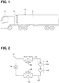
FIG. 1 is a diagram illustrating a refrigeration device and a refrigerated container according to a first embodiment. -
FIG. 2 is a diagram illustrating a refrigerator circuit of the refrigeration device according to the first embodiment. -
FIG. 3 is a front view showing the refrigeration device according to the first embodiment. -
FIG. 4 is a cross-section of the refrigeration device taken in a vertical direction, according to the first embodiment. -
FIG. 5 is a cross-sectional view of a duct shown inFIG. 3 . - Hereinafter, embodiments of the present disclosure will be described with reference to the drawings. The directions indicated by arrows in
FIGS. 3 ,4 ,5 represent the direction when arefrigeration device 10 is installed on atrailer 1. - As shown in
FIG. 1 , therefrigeration device 10 of the present embodiment is disposed in a refrigeratedcontainer 2 of thetrailer 1. Thetrailer 1 is a vehicle for transportation of the refrigerated container towed by atractor 3 The refrigeratedcontainer 2 is a refrigerated container for transportation transported by a vehicle. The refrigeratedcontainer 2 is a container that keeps internal air at a lower temperature than external air. - As shown in
FIG. 2 , therefrigeration device 10 includes arefrigerator circuit 12 constituting a vapor compression refrigeration cycle. Anelectric compressor 14, arefrigerant radiator 16, anexpansion valve 18, and anevaporator 20 are disposed in therefrigerant circuit 12. Theelectric compressor 14, therefrigerant radiator 16, theexpansion valve 18, and theevaporator 20 are connected with each other throughpipes 22. - The
electric compressor 14 constitutes a part of the vapor compression refrigeration cycle. Theelectric compressor 14 compresses and discharges the refrigerant drawn therein. Theelectric compressor 14 includes afirst compressor 142 and asecond compressor 144. Thefirst compressor 142 compresses and discharges the refrigerant drawn therein. Thesecond compressor 144 draws the refrigerant discharged from thefirst compressor 142, and discharges the refrigerant after compressing. Theelectric compressor 14 is driven by an alternating current converted by theinverter 40 described later. - The
refrigerant radiator 16 causes the refrigerant discharged by theelectric compressor 14 to release heat. Therefrigerant radiator 16 is an heat exchanger for exchanging heat between the refrigerant and an air outside the refrigeratedcontainer 2. Theexpansion valve 18 is a decompressor that decompresses and expands the refrigerant flowing out of therefrigerant radiator 16. Theevaporator 20 causes the refrigerant flowing out of theexpansion valve 18 to evaporate. Theevaporator 20 is an heat exchanger for exchanging heat between the refrigerant and the air inside the refrigeratedcontainer 2. Although not shown, therefrigeration device 10 includes an injection passage, an intermediate pressure expansion valve, and an internal heat exchanger. The injection passage causes a part of the refrigerant flowing out of therefrigerant radiator 16 to flow into a part between thefirst compressor 142 and thesecond compressor 144. The intermediate pressure expansion valve decompresses and expands the refrigerant flowing through the injection passage such that the refrigerant becomes an intermediate-pressure refrigerant. The intermediate-pressure refrigerant is a refrigerant having a pressure between a low-pressure refrigerant drawn by theelectric compressor 14 and a high-pressure refrigerant discharged by theelectric compressor 14. The internal heat exchanger exchanges heat between the high-pressure refrigerant flowing from therefrigerant radiator 16 toward theexpansion valve 18 and the intermediate-pressure refrigerant in the injection passage flowing from the intermediate pressure expansion valve toward theelectric compressor 14. - The
refrigeration device 10 includes aradiator fan 24 and anevaporator fan 26. Theradiator fan 24 is configured to convey the air outside the refrigeratedcontainer 2 to therefrigerant radiator 16. Theevaporator fan 26 is configured to convey the air inside the refrigeratedcontainer 2 to theevaporator 20. - As shown in
FIGS. 3 ,4 , therefrigeration device 10 includes aframe 30. Theframe 30 is a support member that supports components of therefrigeration device 10. Theframe 30 forms a framework of therefrigeration device 10. The components are fixed to theframe 30. The components are unitized to be the unit 11. Theframe 30 includes a vertical member 302 extending in a vertical direction and a lateral member 304 extending in a horizontal direction. - As shown in
FIG. 3 , therefrigerant radiator 16 and theradiator fan 24 are located in an upper side the unit 11. The upper side of the unit 11 is a position above a middle part of theframe 30 in an up-down direction (e.g. vertical direction). Theradiator fan 24 is located higher than therefrigerant radiator 16. - As shown in
FIG. 4 , theevaporator 20 and theevaporator fan 26 are located in the upper side of the unit 11. Therefrigeration device 10 includes an airflow path member 32. The airflow path member 32 forms an air flow path for the air inside therefrigerated container 2. The airflow path member 32 is located in the upper side of the unit. The airflow path member 32 is aligned with therefrigerant radiator 16 in a front-rear direction of the vehicle. Theevaporator 20 and theevaporator fan 26 are disposed in the airflow path member 32. Theevaporator 20 and theevaporator fan 26 are fixed to theframe 30 through the airflow path member 32. Theevaporator 20 and theevaporator fan 26 may be directly fixed to theframe 30 not to the airflow path member 32. The airflow path member 32 has anair inlet 322 and anair outlet 324. The air inside therefrigerated container 2 flows into the airflow path member 32 from theair inlet 322. The air that has passed through theevaporator 20 flows into therefrigerated container 2 from theair outlet 324. - As shown in
FIGS. 3 ,4 , therefrigeration device 10 includes anengine 34, aradiator 36, agenerator 38, and theinverter 40. - The
engine 34 drives thegenerator 38. Theengine 34 is an engine dedicated to driving thegenerator 38. Theengine 34 is an internal combustion engine for generating power. Theradiator 36 is a coolant radiator configured to release heat of the coolant of theengine 34 to the air outside therefrigerated container 2. - The
generator 38 is driven by theengine 34. Thegenerator 38 generates electric power. Theinverter 40 is configured to convert the electric power generated by thegenerator 38 into the alternating electric power that has a predetermined voltage and a predetermined frequency. Theinverter 40 is configured to supply the converted alternating current to theelectric compressor 14 and the like. Theinverter 40 includes aheat radiation fin 402. Theheat radiation fin 402 is a heat radiation member that causes theinverter 40 to release heat to the air around theinverter 40. A corrugated fin is used as theheat radiation fin 402. - As shown in
FIG. 3 , theelectric compressor 14, theengine 34, thegenerator 38, and theinverter 40 are located in a lower side of the unit 11. The lower side of the unit 11 is a position below the middle part of theframe 30 in the up-down direction. The middle part of theframe 30 in the up-down direction is a middle part between an upper end of theframe 30 and a lower end of theframe 30. - The
generator 38 is located on a side of theengine 34. Thefirst compressor 142 and thesecond compressor 144 are located on the side of thegenerator 38. The side means one of a left side or a right side. An upper end of thesecond compressor 144 is located higher than an upper end of thefirst compressor 142 in the up-down direction. The upper end of thesecond compressor 144 may be at the same position as the upper end of thefirst compressor 142 in the up-down direction. The upper end of thesecond compressor 144 may be located lower than the upper end of thefirst compressor 142 in the up-down direction. Theinverter 40 is located lower than both thegenerator 38 and theengine 34. - As shown in
FIG. 4 , theradiator 36 is located in the upper side of the unit 11. Theradiator 36 is aligned with therefrigerant radiator 16 in the front-rear direction of the vehicle. - As shown in
FIG. 3 , therefrigeration device 10 includes acontroller 42. Thecontroller 42 controls theengine 34, theelectric compressor 14, theradiator fan 24, and theevaporator fan 26. Thecontroller 42 is located in the lower side of the unit 11. Thecontroller 42 is located on the other side of theengine 34 opposite from thegenerator 38. - As shown in
FIGS. 3 ,4 ,5 , therefrigeration device 10 includes aduct 44 and agenerator fan 46. - The
duct 44 forms therein an air flow path. Theduct 44 guides the air outside therefrigerated container 2 to thegenerator 38 via a surface of theheat radiation fin 402. Oneend 442 of theduct 44 is joined to thegenerator 38. Theother end 444 of theduct 44 is located below theinverter 40. - A part of the
heat radiation fin 402 is located in theduct 44. Specifically, theheat radiation fin 402 penetrates theduct 44. Theheat radiation fin 402 extends from theinverter 40 to the inside of theduct 44. - The
generator fan 46 is a fan configured to cause the air in theduct 44 to flow toward thegenerator 38. Thegenerator fan 46 is located in a part of theduct 44 close to thegenerator 38. - Accordingly, the
duct 44 extends from thegenerator 38 to theheat radiation fin 402. Thegenerator fan 46 and theheat radiation fin 402 are connected through theduct 44. - Next, the operation of the
refrigeration device 10 of the present embodiment will be described. - When an operation switch (not shown) is turned on, the
refrigeration device 10 is put into operation. When therefrigeration device 10 is in operation, thecontroller 42 actuates theengine 34. The actuation of theengine 34 causes thegenerator 38 to generate electric power. The electric power is converted by theinverter 40 into the predetermined alternating electric power. The converted electric power is supplied to theelectric compressor 14, theradiator fan 24, and theevaporator fan 26 shown inFIG. 2 . As a result, theelectric compressor 14, theradiator fan 24, and theevaporator fan 26 are actuated. That is, the vapor compression refrigeration cycle is actuated. - Specifically, the refrigerant is compressed by the
electric compressor 14. The compressed refrigerant flows into therefrigerant radiator 16. The refrigerant releases heat at therefrigerant radiator 16 by exchanging heat with the air outside the refrigerated container. The refrigerant that has released heat is decompressed and expanded at theexpansion valve 18. The refrigerant flowing out of theexpansion valve 18 flows into theevaporator 20. The refrigerant evaporates in theevaporator 20 due to the heat exchange with the air inside the refrigerated container. The evaporated refrigerant is drawn into theelectric compressor 14. - At this time, as shown in
FIG. 4 , theevaporator fan 26 causes the air inside therefrigerated container 2 to flow into the airflow path member 32 from theair inlet 322. The air flowing into the airflow path member 32 passes through theevaporator 20. The air is cooled by exchanging heat with the refrigerant. The cooled air flows into therefrigerated container 2 from theair outlet 324. The inside of therefrigerated container 2 is cooled by the cooled air. In this way, freezing and refrigeration of the inside of therefrigerated container 2 are performed. - The
generator fan 46 is attached to a rotor (not shown) of thegenerator 38. As the rotor of thegenerator 38 rotates, thegenerator fan 46 rotates. Accordingly, thegenerator fan 46 is actuated along with thegenerator 38 when therefrigeration device 10 is in operation. As thegenerator fan 46 is operated, the air outside therefrigerated container 2 flows through theduct 44 from theother end 444 of theduct 44 towardgenerator 38. - At this time, the air outside the
refrigerated container 2 flows along the surface of theheat radiation fin 402. Accordingly, the heat of theinverter 40 is released from theheat radiation fin 402 to the air outside the refrigerated container. That is, theinverter 40 is cooled. The air that has passed through theheat radiation fin 402 flows through thegenerator 38. As a result, thegenerator 38 is cooled. - As described above, the
refrigeration device 10 of the present embodiment includes theengine 34, thegenerator 38, theinverter 40, theelectric compressor 14, and theframe 30. Theengine 34, thegenerator 38, and theelectric compressor 14 are located lower than the middle part of theframe 30 in the up-down direction. - In general refrigeration devices, the
inverter 40 is located on a side of thegenerator 38. In contrast, in therefrigeration device 10 of the present embodiment, theinverter 40 is located lower than thegenerator 38. Accordingly, the space for theelectric compressor 14 can be secured in the lower side of the unit 11. Therefore, theelectric compressor 14 can be disposed in the lower side of the unit 11. - In the
refrigeration device 10 of the present embodiment, theelectric compressor 14 is disposed in the lower side of the unit 11 as well as theengine 34 and thegenerator 38. Accordingly, it is possible, by positioning theelectric compressor 14 in the lower side of the unit, to reduce the burden of lifting theelectric compressor 14 at the time of manufacturing therefrigeration device 10 or performing maintenance. - The heat generated from the
generator 38 is transferred upward by the natural convection of the air around thegenerator 38. Accordingly, the heat transfer from thegenerator 38 to theinverter 40 can be suppressed. - Further, in the
refrigeration device 10 of the present embodiment, theinverter 40 includes theheat radiation fin 402. Therefrigeration device 10 of the present embodiment includes theduct 44 and thegenerator fan 46. By driving thegenerator fan 46, the air outside therefrigerated container 2 is guided to thegenerator 38 via the surface of theheat radiation fin 402. As a result, theinverter 40 can be forcibly cooled by the air outside the refrigerated container. Accordingly, the cooling performance for cooling theinverter 40 can be improved as compared to a case where theinverter 40 is not forcibly cooled. -
- (1) In the above-described embodiment, the one
end 442 of theduct 44 is joined to thegenerator 38. However, the oneend 442 of theduct 44 may be separated from thegenerator 38 as long as the air can be guided to thegenerator 38 from theduct 44.
Further, a part of theheat radiation fin 402 is disposed in theduct 44. However, theheat radiation fin 402 may not be disposed in theduct 44 as long as the air outside therefrigerated container 2 can be guided to thegenerator 38 via the surface of theheat radiation fin 402. For example, theother end 444 of theduct 44 may be located at a part close to theheat radiation fin 402.
As described above, the positional relationship between theheat radiation fin 402 and theduct 44 is not limited to the above-described embodiment. The other positional relationships are acceptable as long as theduct 44 and theheat radiation fin 402 are arranged such that the air outside the refrigerated container flows to thegenerator 38 via the surface of theheat radiation fin 402. - (2) In the above-described embodiment, the
heat radiation fin 402 is used as a heat radiation member of theinverter 40. However, a member having a different shape than a fin may be used as the heat radiation member of theinverter 40. - (3) In the above-described embodiment, the
refrigeration device 10 includes theduct 44. However, therefrigeration device 10 may not include theduct 44. Even in this case, the heat transfer from thegenerator 38 to theinverter 40 can be suppressed by arranging theinverter 40 at a position lower than thegenerator 38 in the up-down direction. - (4) In the above-described embodiment, the
electric compressor 14 is located on a side of thegenerator 38 in the left-right direction of the vehicle. However, theelectric compressor 14 may be located on a side of the generator in the front-rear direction of the vehicle. That is, other positional relationships are acceptable as long as theelectric compressor 14 is aligned with thegenerator 38 in the horizontal direction. Moreover, theelectric compressor 14 may not be aligned with thegenerator 38 in the horizontal direction as long as theelectric compressor 14 is disposed in the lower side of the unit 11. - (5) In the above-described embodiment, the
electric compressor 14 includes thefirst compressor 142 and thesecond compressor 144. However, theelectric compressor 14 may include only one compressor. - (6) In the above-described embodiment, the
refrigeration device 10 is installed in the refrigerated container for transportation transported by a vehicle. However, therefrigeration device 10 may be installed in a refrigerated container for transportation transported by a ship, a train or the like. - (7) The present disclosure is not limited to the foregoing description of the embodiments and can be modified within the scope of the present disclosure. The present disclosure may also be varied in many ways. Such variations are not to be regarded as departure from the disclosure, and all such modifications are intended to be included within the scope of the disclosure. The above embodiments are not independent of each other, and can be appropriately combined together except when the combination is obviously impossible. Further, in each of the above-mentioned embodiments, it goes without saying that components of the embodiment are not necessarily essential except for a case in which the components are particularly clearly specified as essential components, a case in which the components are clearly considered in principle as essential components, and the like. A quantity, a value, an amount, a range, or the like, if specified in the above-described example embodiments, is not necessarily limited to the specific value, amount, range, or the like unless it is specifically stated that the value, amount, range, or the like is necessarily the specific value, amount, range, or the like, or unless the value, amount, range, or the like is obviously necessary to be the specific value, amount, range, or the like in principle. Further, in each of the embodiments described above, when materials, shapes, positional relationships, and the like, of the components and the like, are mentioned, they are not limited to these materials, shapes, positional relationships, and the like, unless otherwise specified and unless limited to specific materials, shapes, positional relationships, and the like.
- According to a first aspect described in a part or all of the embodiments, the refrigeration device disposed in the refrigerated container for transportation includes the engine, the generator, the inverter, the electric compressor, and the support member. The support member supports the engine, the generator, the inverter, and the electric compressor. The engine, the generator, and the electric compressor are located lower than a middle part of the support member in a vertical direction. The inverter is located lower than the generator in the vertical direction.
- According to a second aspect, the inverter has a heat radiation member configured to release heat of the inverter to the air around the inverter. The refrigeration device includes: a duct that guides the air outside the refrigerated container for transportation to the generator via a surface of the heat radiation member; and a fan configured to cause the air in the duct to flow from the heat radiation member to the generator.
- As a result, the inverter can be forcibly cooled by the air outside the refrigerated container. Accordingly, the cooling performance for cooling the inverter can be improved as compared to a case where the inverter is not forcibly cooled.
- According to a third aspect, a part of the heat radiation member is located in the duct. The configuration of the third aspect can be used as a specific structure in the second aspect.
- According to a fourth aspect, the electric compressor is aligned with the generator in a horizontal direction. The configuration of the fourth aspect can be used as a specific structure in the first to third aspects.
Claims (4)
- A refrigeration device disposed in a refrigerated container (2) for transportation, the refrigeration device comprising:an engine (34);a generator (38) driven by the engine;an inverter (40) configured to convert electric power generated by the generator;an electric compressor (14) driven by the electric power converted by the inverter (40), the electric compressor constituting a part of a vapor compression refrigeration cycle; anda support member (30) that supports the engine, the generator, the inverter, and the electric compressor, whereinthe engine, the generator, and the electric compressor are located lower than a middle part of the support member in a vertical direction, andthe inverter is located lower than the generator in the vertical direction.
- The refrigeration device according to claim 1, wherein
the inverter has a heat radiation member (402) configured to release heat of the inverter to an air around the inverter,
the refrigeration device further comprises:a duct (44) that guides the air outside the refrigerated container for transportation to the generator via a surface of the heat radiation member; anda fan (46) configured to cause the air in the duct to flow from the heat radiation member to the generator. - The refrigeration device according to claim 2, wherein
a part of the heat radiation member is located in the duct. - The refrigeration device according to any one of claims 1 to 3, wherein
the electric compressor is aligned with the generator in a horizontal direction.
Applications Claiming Priority (2)
| Application Number | Priority Date | Filing Date | Title |
|---|---|---|---|
| JP2018006557A JP2019124424A (en) | 2018-01-18 | 2018-01-18 | Refrigeration device |
| PCT/JP2018/044945 WO2019142532A1 (en) | 2018-01-18 | 2018-12-06 | Refrigeration device |
Publications (2)
| Publication Number | Publication Date |
|---|---|
| EP3742089A1 true EP3742089A1 (en) | 2020-11-25 |
| EP3742089A4 EP3742089A4 (en) | 2021-03-10 |
Family
ID=67301787
Family Applications (1)
| Application Number | Title | Priority Date | Filing Date |
|---|---|---|---|
| EP18901688.4A Withdrawn EP3742089A4 (en) | 2018-01-18 | 2018-12-06 | REFRIGERATION DEVICE |
Country Status (5)
| Country | Link |
|---|---|
| US (1) | US20200333058A1 (en) |
| EP (1) | EP3742089A4 (en) |
| JP (1) | JP2019124424A (en) |
| CN (1) | CN111615611A (en) |
| WO (1) | WO2019142532A1 (en) |
Families Citing this family (4)
| Publication number | Priority date | Publication date | Assignee | Title |
|---|---|---|---|---|
| JP2021196114A (en) * | 2020-06-15 | 2021-12-27 | 三菱重工業株式会社 | Refrigeration machine for transportation, and transportation machine |
| JP7470581B2 (en) | 2020-06-26 | 2024-04-18 | 三菱重工業株式会社 | Transport refrigeration equipment and transport equipment |
| CN114659291A (en) * | 2022-04-15 | 2022-06-24 | 超酷(上海)制冷设备有限公司 | A pure electric refrigeration unit and heavy truck |
| US20240093930A1 (en) * | 2022-09-16 | 2024-03-21 | Carrier Corporation | Cooling system for a variable frequency drive in a transport refrigeration unit |
Family Cites Families (9)
| Publication number | Priority date | Publication date | Assignee | Title |
|---|---|---|---|---|
| US5916253A (en) * | 1998-05-04 | 1999-06-29 | Carrier Corporation | Compact trailer refrigeration unit |
| JP2003097881A (en) * | 2001-09-20 | 2003-04-03 | Mitsubishi Heavy Ind Ltd | Refrigeration unit for container |
| JP4262172B2 (en) * | 2004-09-06 | 2009-05-13 | セイレイ工業株式会社 | Container refrigeration equipment |
| JP2008008514A (en) * | 2006-06-27 | 2008-01-17 | Yanmar Co Ltd | Refrigerating container |
| JP2008008515A (en) * | 2006-06-27 | 2008-01-17 | Yanmar Co Ltd | Refrigerating container |
| JP5097486B2 (en) * | 2007-09-12 | 2012-12-12 | 三洋電機株式会社 | Air conditioner |
| EP2436543B1 (en) * | 2009-05-25 | 2018-09-05 | Daikin Industries, Ltd. | Refrigeration device for trailer |
| WO2015045252A1 (en) * | 2013-09-30 | 2015-04-02 | ダイキン工業株式会社 | Refrigeration device for container |
| JP2016056998A (en) * | 2014-09-09 | 2016-04-21 | 株式会社デンソー | Refrigerator and refrigeration system for container |
-
2018
- 2018-01-18 JP JP2018006557A patent/JP2019124424A/en active Pending
- 2018-12-06 WO PCT/JP2018/044945 patent/WO2019142532A1/en not_active Ceased
- 2018-12-06 EP EP18901688.4A patent/EP3742089A4/en not_active Withdrawn
- 2018-12-06 CN CN201880086711.1A patent/CN111615611A/en active Pending
-
2020
- 2020-07-07 US US16/922,820 patent/US20200333058A1/en not_active Abandoned
Also Published As
| Publication number | Publication date |
|---|---|
| JP2019124424A (en) | 2019-07-25 |
| US20200333058A1 (en) | 2020-10-22 |
| WO2019142532A1 (en) | 2019-07-25 |
| EP3742089A4 (en) | 2021-03-10 |
| CN111615611A (en) | 2020-09-01 |
Similar Documents
| Publication | Publication Date | Title |
|---|---|---|
| US20200333058A1 (en) | Refrigeration device | |
| CN107428223B (en) | Transport refrigeration unit with multiple compressors | |
| EP2897824B1 (en) | Electrical transport refrigeration system | |
| JP2011084102A (en) | Cooling device for vehicle | |
| EP2436543B1 (en) | Refrigeration device for trailer | |
| US8312737B2 (en) | Economizer heat exchanger | |
| US8141380B2 (en) | Air refrigerant type cooling apparatus and air refrigerant cooling/heating system using refrigerant type cooling apparatus | |
| CN108332455A (en) | Refrigerant cycle and method for operating a refrigerant cycle | |
| CN103547467A (en) | Cooling system | |
| US9732993B2 (en) | Refrigerant circuit and method of controlling such a circuit | |
| CN102777283A (en) | Rankine cycle apparatus | |
| US20070144201A1 (en) | Air conditioning systems for vehicles | |
| JP2006097911A (en) | Heat exchanger | |
| WO2009006918A1 (en) | Compression refrigerating machine | |
| JP2014163624A (en) | Turbo refrigerator | |
| CN103338951A (en) | cooling equipment | |
| KR101754497B1 (en) | Heat pump type air conditioning device for electric vehicle using wind power generator | |
| JP2016153713A (en) | Ejector cycle | |
| KR102181352B1 (en) | Air conditioning module and system for battery | |
| KR200467801Y1 (en) | Refrigerating system | |
| JP2008273220A (en) | Cooling device for vehicle | |
| CZ306829B6 (en) | A cooling circuit for cooling medium circulation | |
| JP2016180523A (en) | Refrigeration device for land transportation | |
| KR20170036366A (en) | Cooling module and Cooling System for Vehicles | |
| JP2003276426A (en) | Air conditioner for vehicle |
Legal Events
| Date | Code | Title | Description |
|---|---|---|---|
| STAA | Information on the status of an ep patent application or granted ep patent |
Free format text: STATUS: THE INTERNATIONAL PUBLICATION HAS BEEN MADE |
|
| PUAI | Public reference made under article 153(3) epc to a published international application that has entered the european phase |
Free format text: ORIGINAL CODE: 0009012 |
|
| STAA | Information on the status of an ep patent application or granted ep patent |
Free format text: STATUS: REQUEST FOR EXAMINATION WAS MADE |
|
| 17P | Request for examination filed |
Effective date: 20200701 |
|
| AK | Designated contracting states |
Kind code of ref document: A1 Designated state(s): AL AT BE BG CH CY CZ DE DK EE ES FI FR GB GR HR HU IE IS IT LI LT LU LV MC MK MT NL NO PL PT RO RS SE SI SK SM TR |
|
| AX | Request for extension of the european patent |
Extension state: BA ME |
|
| STAA | Information on the status of an ep patent application or granted ep patent |
Free format text: STATUS: EXAMINATION IS IN PROGRESS |
|
| A4 | Supplementary search report drawn up and despatched |
Effective date: 20210209 |
|
| RIC1 | Information provided on ipc code assigned before grant |
Ipc: F25B 27/00 20060101ALN20210203BHEP Ipc: F25D 19/00 20060101ALI20210203BHEP Ipc: F25B 1/10 20060101ALN20210203BHEP Ipc: F25D 11/00 20060101AFI20210203BHEP Ipc: B60H 1/00 20060101ALI20210203BHEP Ipc: F25B 31/00 20060101ALN20210203BHEP Ipc: F25B 49/02 20060101ALI20210203BHEP Ipc: B60K 5/00 20060101ALI20210203BHEP Ipc: B60P 3/20 20060101ALI20210203BHEP |
|
| 17Q | First examination report despatched |
Effective date: 20210219 |
|
| DAV | Request for validation of the european patent (deleted) | ||
| DAX | Request for extension of the european patent (deleted) | ||
| STAA | Information on the status of an ep patent application or granted ep patent |
Free format text: STATUS: THE APPLICATION HAS BEEN WITHDRAWN |
|
| 18W | Application withdrawn |
Effective date: 20210525 |