EP3742086A1 - Ice making system - Google Patents
Ice making system Download PDFInfo
- Publication number
- EP3742086A1 EP3742086A1 EP18899412.3A EP18899412A EP3742086A1 EP 3742086 A1 EP3742086 A1 EP 3742086A1 EP 18899412 A EP18899412 A EP 18899412A EP 3742086 A1 EP3742086 A1 EP 3742086A1
- Authority
- EP
- European Patent Office
- Prior art keywords
- ice making
- icing
- ice
- refrigerant
- cooled
- Prior art date
- Legal status (The legal status is an assumption and is not a legal conclusion. Google has not performed a legal analysis and makes no representation as to the accuracy of the status listed.)
- Granted
Links
Images





Classifications
-
- F—MECHANICAL ENGINEERING; LIGHTING; HEATING; WEAPONS; BLASTING
- F25—REFRIGERATION OR COOLING; COMBINED HEATING AND REFRIGERATION SYSTEMS; HEAT PUMP SYSTEMS; MANUFACTURE OR STORAGE OF ICE; LIQUEFACTION SOLIDIFICATION OF GASES
- F25C—PRODUCING, WORKING OR HANDLING ICE
- F25C1/00—Producing ice
- F25C1/08—Producing ice by immersing freezing chambers, cylindrical bodies or plates into water
-
- F—MECHANICAL ENGINEERING; LIGHTING; HEATING; WEAPONS; BLASTING
- F25—REFRIGERATION OR COOLING; COMBINED HEATING AND REFRIGERATION SYSTEMS; HEAT PUMP SYSTEMS; MANUFACTURE OR STORAGE OF ICE; LIQUEFACTION SOLIDIFICATION OF GASES
- F25B—REFRIGERATION MACHINES, PLANTS OR SYSTEMS; COMBINED HEATING AND REFRIGERATION SYSTEMS; HEAT PUMP SYSTEMS
- F25B13/00—Compression machines, plants or systems, with reversible cycle
-
- F—MECHANICAL ENGINEERING; LIGHTING; HEATING; WEAPONS; BLASTING
- F25—REFRIGERATION OR COOLING; COMBINED HEATING AND REFRIGERATION SYSTEMS; HEAT PUMP SYSTEMS; MANUFACTURE OR STORAGE OF ICE; LIQUEFACTION SOLIDIFICATION OF GASES
- F25C—PRODUCING, WORKING OR HANDLING ICE
- F25C1/00—Producing ice
- F25C1/12—Producing ice by freezing water on cooled surfaces, e.g. to form slabs
- F25C1/14—Producing ice by freezing water on cooled surfaces, e.g. to form slabs to form thin sheets which are removed by scraping or wedging, e.g. in the form of flakes
- F25C1/145—Producing ice by freezing water on cooled surfaces, e.g. to form slabs to form thin sheets which are removed by scraping or wedging, e.g. in the form of flakes from the inner walls of cooled bodies
-
- F—MECHANICAL ENGINEERING; LIGHTING; HEATING; WEAPONS; BLASTING
- F25—REFRIGERATION OR COOLING; COMBINED HEATING AND REFRIGERATION SYSTEMS; HEAT PUMP SYSTEMS; MANUFACTURE OR STORAGE OF ICE; LIQUEFACTION SOLIDIFICATION OF GASES
- F25C—PRODUCING, WORKING OR HANDLING ICE
- F25C5/00—Working or handling ice
- F25C5/02—Apparatus for disintegrating, removing or harvesting ice
- F25C5/04—Apparatus for disintegrating, removing or harvesting ice without the use of saws
- F25C5/08—Apparatus for disintegrating, removing or harvesting ice without the use of saws by heating bodies in contact with the ice
- F25C5/10—Apparatus for disintegrating, removing or harvesting ice without the use of saws by heating bodies in contact with the ice using hot refrigerant; using fluid heated by refrigerant
-
- F—MECHANICAL ENGINEERING; LIGHTING; HEATING; WEAPONS; BLASTING
- F25—REFRIGERATION OR COOLING; COMBINED HEATING AND REFRIGERATION SYSTEMS; HEAT PUMP SYSTEMS; MANUFACTURE OR STORAGE OF ICE; LIQUEFACTION SOLIDIFICATION OF GASES
- F25C—PRODUCING, WORKING OR HANDLING ICE
- F25C2301/00—Special arrangements or features for producing ice
- F25C2301/002—Producing ice slurries
-
- F—MECHANICAL ENGINEERING; LIGHTING; HEATING; WEAPONS; BLASTING
- F25—REFRIGERATION OR COOLING; COMBINED HEATING AND REFRIGERATION SYSTEMS; HEAT PUMP SYSTEMS; MANUFACTURE OR STORAGE OF ICE; LIQUEFACTION SOLIDIFICATION OF GASES
- F25C—PRODUCING, WORKING OR HANDLING ICE
- F25C2400/00—Auxiliary features or devices for producing, working or handling ice
- F25C2400/10—Refrigerator units
-
- F—MECHANICAL ENGINEERING; LIGHTING; HEATING; WEAPONS; BLASTING
- F25—REFRIGERATION OR COOLING; COMBINED HEATING AND REFRIGERATION SYSTEMS; HEAT PUMP SYSTEMS; MANUFACTURE OR STORAGE OF ICE; LIQUEFACTION SOLIDIFICATION OF GASES
- F25C—PRODUCING, WORKING OR HANDLING ICE
- F25C2400/00—Auxiliary features or devices for producing, working or handling ice
- F25C2400/14—Water supply
-
- F—MECHANICAL ENGINEERING; LIGHTING; HEATING; WEAPONS; BLASTING
- F25—REFRIGERATION OR COOLING; COMBINED HEATING AND REFRIGERATION SYSTEMS; HEAT PUMP SYSTEMS; MANUFACTURE OR STORAGE OF ICE; LIQUEFACTION SOLIDIFICATION OF GASES
- F25C—PRODUCING, WORKING OR HANDLING ICE
- F25C2500/00—Problems to be solved
- F25C2500/08—Sticking or clogging of ice
-
- F—MECHANICAL ENGINEERING; LIGHTING; HEATING; WEAPONS; BLASTING
- F25—REFRIGERATION OR COOLING; COMBINED HEATING AND REFRIGERATION SYSTEMS; HEAT PUMP SYSTEMS; MANUFACTURE OR STORAGE OF ICE; LIQUEFACTION SOLIDIFICATION OF GASES
- F25C—PRODUCING, WORKING OR HANDLING ICE
- F25C2600/00—Control issues
- F25C2600/04—Control means
-
- F—MECHANICAL ENGINEERING; LIGHTING; HEATING; WEAPONS; BLASTING
- F25—REFRIGERATION OR COOLING; COMBINED HEATING AND REFRIGERATION SYSTEMS; HEAT PUMP SYSTEMS; MANUFACTURE OR STORAGE OF ICE; LIQUEFACTION SOLIDIFICATION OF GASES
- F25C—PRODUCING, WORKING OR HANDLING ICE
- F25C2700/00—Sensing or detecting of parameters; Sensors therefor
-
- F—MECHANICAL ENGINEERING; LIGHTING; HEATING; WEAPONS; BLASTING
- F25—REFRIGERATION OR COOLING; COMBINED HEATING AND REFRIGERATION SYSTEMS; HEAT PUMP SYSTEMS; MANUFACTURE OR STORAGE OF ICE; LIQUEFACTION SOLIDIFICATION OF GASES
- F25C—PRODUCING, WORKING OR HANDLING ICE
- F25C2700/00—Sensing or detecting of parameters; Sensors therefor
- F25C2700/14—Temperature of water
Definitions
- the present disclosure relates to an ice making system.
- Patent Literature 1 discloses an ice making refrigeration apparatus including a double-pipe flooded evaporator having an inner pipe through which a medium to be cooled flows, and an outer pipe containing the inner pipe.
- This ice making refrigeration apparatus expands, with an expansion mechanism, high-pressure liquid refrigerant flowing out of a condenser to reduce the pressure of the refrigerant, and supplies the low-pressure liquid refrigerant into an outer cooling chamber provided between the inner pipe and the outer pipe of the flooded evaporator.
- the medium to be cooled flowing through the inner pipe is cooled, while the liquid refrigerant in the outer cooling chamber evaporates.
- the medium to be cooled in the inner pipe turns into slurry ice after the subcooled state of the medium is undone by a rotary blade.
- the low-pressure refrigerant that has evaporated in the outer cooling chamber is discharged from the flooded evaporator and returned to a suction side of a compressor.
- Patent Literature 1 Japanese Unexamined Patent Publication No. 2003-185285
- An object of the present disclosure is to provide an ice making system that can eliminate, at an early stage, ice lock that has occurred in an ice making machine.
- An ice making system of the present disclosure includes:
- This configuration makes it possible to detect that ice lock has occurred in the ice making machine and to perform the de-icing operation.
- the control device preferably stops the pump during the de-icing operation.
- This configuration makes it possible to suppress the melting of the ice in the tank, which would be caused by a temperature rise in the tank.
- the ice making system further includes a refrigerant circuit that is formed by connecting, with a refrigerant pipe, a compressor, a heat source-side heat exchanger, an expansion mechanism, and a utilization-side heat exchanger in that order, the utilization-side heat exchanger constitutes a part of the ice making machine, and exchanges heat with the medium to be cooled in the cooling chamber to evaporate refrigerant during an ice making operation, and the de-icing mechanism includes the refrigerant circuit and a four-way switching valve connected to a discharge side of the compressor in the refrigerant circuit, the four-way switching valve being configured to switch the ice making operation to the de-icing operation by switching a flow path of the refrigerant, discharged from the compressor, from a path leading to the heat source-side heat exchanger to a path leading to the utilization-side heat exchanger.
- a refrigerant circuit that is formed by connecting, with a refrigerant pipe, a compressor, a heat source-side heat exchanger, an
- This configuration makes it possible to perform the de-icing operation using the refrigerant circuit in which the ice making machine makes ice.
- the ice making system preferably includes a first temperature sensor that detects an operating temperature of the de-icing mechanism, and the control device preferably stops the de-icing operation when the temperature detected by the first temperature sensor exceeds a predetermined temperature.
- This configuration makes it possible to appropriately set the timing for stopping the de-icing operation based on the operating temperature of the de-icing mechanism.
- the ice making system preferably includes a second temperature sensor that detects a temperature of the medium to be cooled discharged from the cooling chamber, and the control device preferably stops the de-icing operation when the temperature detected by the second temperature sensor exceeds a predetermined temperature.
- This configuration makes it possible to appropriately set the timing for stopping the de-icing operation based on the temperature of the medium to be cooled discharged from the cooling chamber, and to melt the ice in the cooling chamber to such an extent that the ice lock does not occur again when the de-icing operation is switched back to the ice making operation.
- the predetermined temperature can be, for example, 0°C.
- FIG. 1 is a schematic configuration diagram of an ice making system A according to a first embodiment.
- an ice making machine 1 continuously generates ice slurry using, as a raw material, seawater stored in a seawater tank 8 and stores the generated ice slurry in the seawater tank 8.
- the ice slurry refers to sherbet-like ice in which fine ice is mixed with water or an aqueous solution.
- the ice slurry is also referred to as slurry ice, slush ice, or liquid ice.
- the ice making system A of the present embodiment can continuously generate seawater-based ice slurry. Therefore, the ice making system A of the present embodiment is installed in, for example, a fishing boat or a fishing port, and the ice slurry stored in the seawater tank 8 is used for keeping fresh fish cool.
- the ice making system A of the present embodiment switches operations between an ice making operation of making ice in the ice making machine 1 and a de-icing operation of melting the ice stored in the ice making machine 1.
- the ice making system A uses seawater as a medium to be cooled (object to be cooled).
- the ice making system A includes the ice making machine 1, a compressor 2, a heat source-side heat exchanger 3, a four-way switching valve 4, a utilization-side expansion valve (expansion mechanism) 5, a receiver (liquid receiver) 7, a heat source-side expansion valve (expansion mechanism) 27, a fan 10, the seawater tank (ice storage tank) 8, a pump 9, and the like.
- the ice making system A also includes a control device 50.
- the compressor 2, the heat source-side heat exchanger 3, the heat source-side expansion valve 27, the receiver 7, the utilization-side expansion valve 5, and the ice making machine 1 are connected in that order by a refrigerant pipe to constitute a refrigerant circuit.
- the ice making machine 1, the seawater tank 8, and the pump 9 are connected by a seawater pipe to constitute a circulation circuit.
- the four-way switching valve 4 is connected to a discharge side of the compressor 2.
- the four-way switching valve 4 has a function of switching the direction of flowing refrigerant discharged from the compressor 2, that is, flowing the refrigerant either toward the heat source-side heat exchanger 3 or the ice making machine 1.
- the four-way switching valve 4 switches operations between the ice making operation and the de-icing operation.
- the compressor 2 compresses the refrigerant and circulates the refrigerant in the refrigerant circuit.
- the compressor 2 is of a variable displacement type (variable capacity type). Specifically, the compressor 2 can change the number of rotations of a built-in motor stepwise or continuously by controlling the motor with an inverter.
- the fan 10 cools the heat source-side heat exchanger 3 with air.
- the fan 10 includes a motor, the number of rotations of which is changed stepwise or continuously through inverter control.
- the utilization-side expansion valve 5 and the heat source-side expansion valve 27 are each configured by, for example, an electronic expansion valve that is driven by a pulse motor, and have an adjustable opening degree.
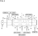
- FIG. 2 is an explanatory side view of the ice making machine.
- FIG. 3 is an explanatory view schematically showing a cross section of the ice making machine.
- the ice making machine 1 is configured by a double-pipe ice making machine.
- the ice making machine 1 includes an evaporator 1A as a utilization-side heat exchanger, and a blade mechanism 15.
- the evaporator 1A includes an inner pipe 12 and an outer pipe 13 each formed in a cylindrical shape.
- the evaporator 1A is installed horizontally, and thus the axes of the inner pipe 12 and the outer pipe 13 extend horizontally.
- the evaporator 1A of the present embodiment is configured by a flooded evaporator.
- the inner pipe 12 is an element through which seawater as a medium to be cooled passes.
- the inner pipe 12 configures a cooling chamber that cools seawater.
- the inner pipe 12 is formed of a metal material. Both ends of the inner pipe 12 in the axial direction are closed.
- An inlet port 16 for seawater is provided at one end of the inner pipe 12 in the axial direction (right side in FIG. 2 ). Seawater is supplied into the inner pipe 12 through the inlet port 16.
- a discharge port 17 for seawater is provided at the other end of the inner pipe 12 in the axial direction (left side in FIG. 2 ). The seawater in the inner pipe 12 is discharged through the discharge port 17.
- the blade mechanism 15 is installed in the inner pipe 12.
- the blade mechanism 15 scrapes up the sherbet-like ice generated on the inner peripheral surface of the inner pipe 12 and disperses the ice inside the inner pipe 12.
- the blade mechanism 15 includes a shaft 20, support bars 21, blades 22, and a drive unit 24.
- the other end of the shaft 20 in the axial direction extends outward from a flange 23 provided at the other end of the inner pipe 12 in the axial direction and is connected to a motor as the drive unit 24.
- the support bars 21 are erected at predetermined intervals on the peripheral surface of the shaft 20, and the blades 22 are attached to the tips of the support bars 21.
- Each of the blades 22 includes, for example, a resin or metal strip member.
- a side edge of the blade 22 on the front side in the rotation direction has a sharp tapered shape.
- the outer pipe 13 is provided coaxially with the inner pipe 12 on the radially outer side of the inner pipe 12.
- the outer pipe 13 is formed of a metal material.
- One or a plurality of (in the present embodiment, three) refrigerant inlets 18 is provided at a lower part of the outer pipe 13.
- One or a plurality of (in the present embodiment, two) refrigerant outlets 19 is provided at an upper part of the outer pipe 13.
- Refrigerant that exchanges heat with seawater flows into an annular space 14 between the inner peripheral surface of the outer pipe 13 and the outer peripheral surface of the inner pipe 12.
- the refrigerant supplied through the refrigerant inlet 18 passes through the annular space 14 and is discharged through the refrigerant outlet 19.
- the ice making system A includes the control device 50.
- the control device 50 includes a CPU and a memory.
- the memory includes, for example, a RAM and a ROM.
- the control device 50 realizes various controls regarding an operation of the ice making system A by the CPU executing a computer program stored in the memory. Specifically, the control device 50 controls the opening degrees of the utilization-side expansion valve 5 and the heat source-side expansion valve 27. The control device 50 also controls the operating frequencies of the compressor 2 and the fan 10. The control device 50 further controls driving and stopping of the drive unit 24 of the blade mechanism 15 and the pump 9. The control device 50 may be provided separately on each of the ice making machine 1 and the heat source-side heat exchanger 3.
- control device on the heat source-side heat exchanger 3 can control operations of the heat source-side expansion valve 27, the fan 10, and the compressor 2, while the control device on the ice making machine 1 can control operations of the utilization-side expansion valve 5, the drive unit 24, and the pump 9.
- the ice making system A is provided with a plurality of sensors. As shown in FIG. 1 , the ice making machine 1 is provided with a temperature sensor (first temperature sensor) 34 that detects a refrigerant temperature in the evaporator 1A.
- the discharge port 17 of the inner pipe 12 is provided with a temperature sensor (second temperature sensor) 33 that detects the temperature of seawater (and ice slurry) discharged from the inner pipe 12.
- the drive unit 24 of the blade mechanism 15 of the ice making machine 1 is provided with a current sensor 35 that detects a current value. Detection signals of these sensors are input to the control device 50 and used for various types of control.
- the temperature sensor 34 in the present embodiment is mounted at, for example, a main body of the evaporator 1A or the refrigerant pipe, that is, a position where it is possible to measure the temperature of the refrigerant that has exchanged heat in a de-icing operation described later.
- FIG. 4 is a schematic configuration diagram of the ice making system showing a flow of refrigerant during an ice making operation.
- the four-way switching valve 4 is maintained in a state shown by the solid lines in FIG. 4 .
- High-temperature, high-pressure gas refrigerant discharged from the compressor 2 flows through the four-way switching valve 4 into the heat source-side heat exchanger 3 functioning as a condenser, exchanges heat with air through the operation of the fan 10, and is condensed and liquefied.
- the liquefied refrigerant flows through the fully opened heat source-side expansion valve 27 and then through the receiver 7, into the utilization-side expansion valve 5.
- the refrigerant is decompressed to have a predetermined low pressure by the utilization-side expansion valve 5, becomes gas-liquid two-phase refrigerant, and is supplied through the refrigerant inlet 18 (see FIG. 2 ) of the ice making machine 1 into the annular space 14 between the inner pipe 12 and the outer pipe 13 that constitute the ice making machine 1.
- the refrigerant supplied into the annular space 14 exchanges heat with seawater that has flowed into the inner pipe 12 through the pump 9, and evaporates.
- the refrigerant that has evaporated in the ice making machine 1 is sucked into the compressor 2.
- the pump 9 sucks seawater from the seawater tank 8 and pumps the seawater into the inner pipe 12 of the ice making machine 1.
- the ice slurry generated in the inner pipe 12 is returned to the seawater tank 8 together with the seawater by a pump pressure.
- the ice slurry returned to the seawater tank 8 rises by buoyancy inside the seawater tank 8 and is accumulated on an upper part of the seawater tank 8.
- a phenomenon may occur in which ice gathers and adheres in the inner pipe 12, and the blade 22 of the blade mechanism 15 is caught by the ice, thus increasing a rotational load. This makes it difficult to continue to operate the ice making machine 1.
- a de-icing operation cleaning operation is performed to melt the ice inside the inner pipe 12.
- step S1 while the ice making system A is performing the ice making operation (step S1), the control device 50 constantly obtains a current value I of the drive unit 24 of the blade mechanism 15 with the current sensor 35 (step S2).
- the control device 50 compares the current value I with a predetermined threshold Ith (step S3) and, when the current value I exceeds the threshold Ith, starts the de-icing operation (step S4).
- control device 50 switches the four-way switching valve 4 and reverses the flow of refrigerant during the ice making operation, thereby starting the de-icing operation.
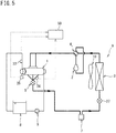
- FIG. 5 is a schematic configuration diagram of the ice making system showing a flow of refrigerant during the de-icing operation.
- the control device 50 switches the four-way switching valve 4 to a state shown by the solid lines in FIG. 5 .
- the high-temperature gas refrigerant discharged from the compressor 2 flows into the annular space 14 between the inner pipe 12 and the outer pipe 13 of the evaporator 1A via the four-way switching valve 4, exchanges heat with seawater containing ice in the inner pipe 12, and is condensed and liquefied. At this time, the ice in the inner pipe 12 is heated by the refrigerant and melted.
- the liquid refrigerant discharged from the evaporator 1A passes through the fully opened utilization-side expansion valve 5, and flows into the heat source-side expansion valve 27 via the receiver 7. After being decompressed by the heat source-side expansion valve 27, the liquid refrigerant evaporates in the heat source-side heat exchanger 3 and is sucked into the compressor 2.
- control device 50 stops the blade mechanism 15 (step S5). This can reduce the load on the blade mechanism 15 and suppress, for example, damage to the blade mechanism 15.
- the control device 50 also stops the pump 9, and stops the circulation of seawater in the ice making machine 1 (step S6). This can suppress the rise in temperature inside the seawater tank 8, and suppress the melting of the ice accumulated in the seawater tank 8.
- the control device 50 determines whether a predetermined condition for stopping the de-icing operation is satisfied and, if the condition is satisfied, stops the de-icing operation and restarts the ice making operation (steps S7, S8). That is, the control device 50 switches the four-way switching valve 4 to the state shown by the solid lines in FIG. 4 , and operates the blade mechanism 15 and the pump 9.
- the de-icing operation can be stopped based on, for example, the following conditions.
- the temperature sensor 34 detects the refrigerant temperature of the evaporator 1A (condenser during the de-icing operation) of the ice making machine 1, that is, the operating temperature of a de-icing mechanism. When the detected temperature exceeds a predetermined threshold, the de-icing operation is stopped.
- the predetermined threshold can be set to a temperature at which ice adhering to a part inside the inner pipe 12 can be sufficiently melted to such an extent that the ice lock is eliminated, for example, set to 10°C.
- the temperature sensor 33 detects the temperature of seawater at the discharge port 17 of the inner pipe 12. When the detected temperature exceeds a predetermined temperature (for example, 0°C), the de-icing operation is stopped. This makes it possible to melt the ice adhering to a part inside the inner pipe 12 to such an extent that the ice lock can be eliminated.
- a predetermined temperature for example, 0°C
- the de-icing operation may be stopped when one of Conditions 1 and 2 described above is satisfied. Alternatively, the de-icing operation may be stopped when both of Conditions 1 and 2 are satisfied. Alternatively, only one of the conditions may be adopted.
- FIG. 7 is a schematic configuration diagram of an ice making system according to a second embodiment.
- a refrigerant circuit of the ice making system A is formed by connecting, with a refrigerant pipe, a compressor 2, a heat source-side heat exchanger 3, a heat source-side expansion valve 27, a receiver 7, a utilization-side expansion valve 5, and an ice making machine 1 in that order.
- the de-icing mechanism in the first embodiment includes the refrigerant circuit and the four-way switching valve 4 provided in the refrigerant circuit.
- the four-way switching valve 4 reverses the flow of the refrigerant during the ice making operation, whereby the de-icing operation is performed.
- a de-icing mechanism of the present embodiment does not include a four-way switching valve like the one in the first embodiment, but includes a bypass refrigerant pipe 41, an on-off valve 42, and an expansion mechanism 43.
- One end of the bypass refrigerant pipe 41 is connected to a refrigerant pipe between the compressor 2 and the heat source-side heat exchanger 3.
- the other end of the bypass refrigerant pipe 41 is connected to a refrigerant pipe between the utilization-side expansion valve 5 and the ice making machine 1.
- the on-off valve 42 is provided in the bypass refrigerant pipe 41, and is opened or closed to allow or block the flow of refrigerant in the bypass refrigerant pipe 41.
- the on-off valve 42 is opened and closed under the control of a control device 50.
- the on-off valve 42 is closed when the ice making operation is performed.
- the on-off valve 42 can be configured by an electromagnetic valve.
- the expansion mechanism 43 decompresses the refrigerant flowing through the bypass refrigerant pipe 41 and lowers the temperature of the refrigerant.
- the expansion mechanism 43 is configured by a capillary tube. Alternatively, the expansion mechanism 43 may be configured by an expansion valve.
- the control device 50 closes the utilization-side expansion valve 5 and the heat source-side expansion valve 27 and opens the on-off valve 42 in order to perform the de-icing operation.
- the high-temperature, high-pressure gas refrigerant discharged from the compressor 2 does not flow to the heat source-side heat exchanger 3 but flows through the bypass refrigerant pipe 41 into the utilization-side heat exchanger 1A of the ice making machine 1.
- the gas refrigerant is decompressed by passing through the expansion mechanism 43 of the bypass refrigerant pipe 41, and becomes medium-temperature, low-pressure gas refrigerant.
- the gas refrigerant flows into the annular space 14 between the inner pipe 12 and the outer pipe 13, exchanges heat with seawater containing ice in the inner pipe 12 to have a lower temperature, and becomes low-temperature, low-pressure gas refrigerant.
- the ice in the inner pipe 12 is heated by the refrigerant and melted.
- the gas refrigerant is discharged from the utilization-side heat exchanger 1A and sucked into the compressor 2.
- the ice making system A of the present embodiment does not require the four-way switching valve 4, thus simplifying the configuration of the refrigerant pipe. Since the utilization-side expansion valve 5 and the heat source-side expansion valve 27 are closed during the de-icing operation, it is not necessary to adjust the opening degree of each of the expansion valves 5 and 27, and the control device 50 can control the expansion valves 5 and 27 in a simplified manner.
- the ice making system A includes: the tank 8 that stores the medium to be cooled; the ice making machine 1 that cools the medium to be cooled and makes ice; the pump 9 that circulates the medium to be cooled between the tank 8 and the ice making machine 1; the de-icing mechanism that performs the de-icing operation of heating and melting the medium to be cooled in the ice making machine 1; and the control device 50 that controls the operations of the ice making machine 1, the pump 9, and the de-icing mechanism.
- the ice making machine 1 includes: the inner pipe 12 as a cooling chamber for cooling the medium to be cooled; the blade mechanism 15 that rotates in the inner pipe 12 to disperse the ice; and the current sensor 35 as a detector that detects a locked state of the blade mechanism 15.
- the control device 50 stops the blade mechanism 15 and operates the de-icing mechanism when, during the de-icing operation, the current sensor 35 detects the locked state of the blade mechanism 15. This makes it possible to detect that the ice lock has occurred in the ice making machine 1 and to perform the de-icing operation.
- the control device 50 stops the pump 9 during the de-icing operation. This makes it possible to suppress the melting of the ice in the tank 8, which would be caused by a temperature rise in the tank 8.
- the ice making system A further includes the refrigerant circuit that is formed by connecting, with the refrigerant pipe, the compressor 2, the heat source-side heat exchanger 3, the heat source-side expansion valve 27 and the utilization-side expansion valve 5 as expansion mechanisms, and the utilization-side heat exchanger 1A in that order.
- the utilization-side heat exchanger 1A constitutes a part of the ice making machine 1, and exchanges heat with the medium to be cooled in the inner pipe 12 to evaporate the refrigerant during the ice making operation.
- the de-icing mechanism of the first embodiment includes the refrigerant circuit and the four-way switching valve 4.
- the four-way switching valve 4 is connected to the discharge side of the compressor 2 in the refrigerant circuit, and switches the ice making operation to the de-icing operation by switching the flow path of the refrigerant, discharged from the compressor 2, from the path leading to the heat source-side heat exchanger 3 to the path leading to the evaporator 1A. In this manner, the de-icing operation can be performed using the refrigerant circuit in which the ice making machine 1 makes ice.
- the ice making system A includes the temperature sensor 34 that detects the operating temperature of the de-icing mechanism.
- the control device 50 stops the de-icing operation when the temperature detected by the temperature sensor 34 exceeds a predetermined temperature. This makes it possible to appropriately set the timing for stopping the de-icing operation based on the operating temperature of the de-icing mechanism.
- the ice making system A includes the temperature sensor 33 that detects the temperature of the medium to be cooled discharged from the inner pipe 12.
- the control device 50 stops the de-icing operation when the temperature detected by the temperature sensor 33 exceeds a predetermined temperature. This makes it possible to appropriately set the timing for stopping the de-icing operation based on the temperature of the medium to be cooled discharged from the inner pipe 12, and to melt the ice in the inner pipe 12 to such an extent that the ice lock does not occur again when the de-icing operation is switched back to the ice making operation.
- the de-icing operation that originally starts in step S4 may alternatively start after step S6, or may start between step S5 and step S6.
- the double-pipe ice making machine is used, but the present invention is not limited to this type of ice making machine.
- the de-icing mechanism may alternatively be an electric heater or a hot-water (or normal-temperature water) heater, for example, that heats the inner pipe (cooling chamber) 12 of the ice making machine 1 from the outside.
- a sensor that measures the temperature of the heater can be adopted as the first temperature sensor 34.
- the first temperature sensor 34 detects the refrigerant temperature in the evaporator 1A that functions as a condenser during the de-icing operation.
- the pressure sensor may detect the pressure (condensation pressure) at the refrigerant outlet or inlet of the evaporator 1A, and the saturation temperature obtained based on the pressure detected by the pressure sensor may be used as the refrigerant temperature of the evaporator 1A.
- the receiver may be omitted in the refrigerant circuit.
- only one expansion valve as an expansion mechanism may be provided in the liquid-side refrigerant pipe between the heat source-side heat exchanger and the utilization-side heat exchanger.
- the medium to be cooled is not limited to seawater, but may be another solution such as ethylene glycol.
- ice making machine in the above embodiments, but a plurality of ice making machines may be connected in series.
- compressor in the above embodiments, but a plurality of compressors may be connected in parallel.
Landscapes
- Engineering & Computer Science (AREA)
- Physics & Mathematics (AREA)
- Mechanical Engineering (AREA)
- Thermal Sciences (AREA)
- General Engineering & Computer Science (AREA)
- Production, Working, Storing, Or Distribution Of Ice (AREA)
- Compression-Type Refrigeration Machines With Reversible Cycles (AREA)
Abstract
Description
- The present disclosure relates to an ice making system.
-
Patent Literature 1 discloses an ice making refrigeration apparatus including a double-pipe flooded evaporator having an inner pipe through which a medium to be cooled flows, and an outer pipe containing the inner pipe. This ice making refrigeration apparatus expands, with an expansion mechanism, high-pressure liquid refrigerant flowing out of a condenser to reduce the pressure of the refrigerant, and supplies the low-pressure liquid refrigerant into an outer cooling chamber provided between the inner pipe and the outer pipe of the flooded evaporator. As a result, the medium to be cooled flowing through the inner pipe is cooled, while the liquid refrigerant in the outer cooling chamber evaporates. The medium to be cooled in the inner pipe turns into slurry ice after the subcooled state of the medium is undone by a rotary blade. The low-pressure refrigerant that has evaporated in the outer cooling chamber is discharged from the flooded evaporator and returned to a suction side of a compressor. - Patent Literature 1: Japanese Unexamined Patent Publication No.
2003-185285 - In this type of ice making refrigeration apparatus, a phenomenon may occur in which ice gathers and adheres to a part inside an inner pipe and a rotary blade is caught by the ice, thus increasing a rotational load (this phenomenon is also referred to as "ice lock"). Such a phenomenon makes it difficult to continuously operate an ice making machine. However, no countermeasures have been taken against these phenomena in the ice making refrigeration apparatus described in
Patent Literature 1. - An object of the present disclosure is to provide an ice making system that can eliminate, at an early stage, ice lock that has occurred in an ice making machine.
- (1) An ice making system of the present disclosure includes:
- a tank that stores a medium to be cooled;
- an ice making machine that cools the medium to be cooled and makes ice;
- a pump that circulates the medium to be cooled between the tank and the ice making machine;
- a de-icing mechanism that performs a de-icing operation of heating and melting the medium to be cooled in the ice making machine; and
- a control device that controls operations of the ice making machine, the pump, and the de-icing mechanism,
- a cooling chamber in which to cool the medium to be cooled;
- a blade mechanism that rotates in the cooling chamber to disperse the ice; and
- a detector that detects a locked state of the blade mechanism, and
- the control device stops the blade mechanism and operates the de-icing mechanism when the detector detects the locked state of the blade mechanism.
- This configuration makes it possible to detect that ice lock has occurred in the ice making machine and to perform the de-icing operation.
- (2) The control device preferably stops the pump during the de-icing operation.
- This configuration makes it possible to suppress the melting of the ice in the tank, which would be caused by a temperature rise in the tank.
- (3) Preferably, the ice making system further includes a refrigerant circuit that is formed by connecting, with a refrigerant pipe, a compressor, a heat source-side heat exchanger, an expansion mechanism, and a utilization-side heat exchanger in that order,
the utilization-side heat exchanger constitutes a part of the ice making machine, and exchanges heat with the medium to be cooled in the cooling chamber to evaporate refrigerant during an ice making operation, and
the de-icing mechanism includes the refrigerant circuit and a four-way switching valve connected to a discharge side of the compressor in the refrigerant circuit, the four-way switching valve being configured to switch the ice making operation to the de-icing operation by switching a flow path of the refrigerant, discharged from the compressor, from a path leading to the heat source-side heat exchanger to a path leading to the utilization-side heat exchanger. - This configuration makes it possible to perform the de-icing operation using the refrigerant circuit in which the ice making machine makes ice.
- (4) The ice making system preferably includes a first temperature sensor that detects an operating temperature of the de-icing mechanism, and the control device preferably stops the de-icing operation when the temperature detected by the first temperature sensor exceeds a predetermined temperature.
- This configuration makes it possible to appropriately set the timing for stopping the de-icing operation based on the operating temperature of the de-icing mechanism.
- (5) The ice making system preferably includes a second temperature sensor that detects a temperature of the medium to be cooled discharged from the cooling chamber, and the control device preferably stops the de-icing operation when the temperature detected by the second temperature sensor exceeds a predetermined temperature.
- This configuration makes it possible to appropriately set the timing for stopping the de-icing operation based on the temperature of the medium to be cooled discharged from the cooling chamber, and to melt the ice in the cooling chamber to such an extent that the ice lock does not occur again when the de-icing operation is switched back to the ice making operation. The predetermined temperature can be, for example, 0°C.
-
- [
FIG. 1] FIG. 1 is a schematic configuration diagram of an ice making system according to a first embodiment. - [
FIG. 2] FIG. 2 is an explanatory side view of an ice making machine. - [
FIG. 3] FIG. 3 is an explanatory view schematically showing a cross section of the ice making machine. - [
FIG. 4] FIG. 4 is a schematic configuration diagram of the ice making system showing a flow of refrigerant during an ice making operation. - [
FIG. 5] FIG. 5 is a schematic configuration diagram of the ice making system showing a flow of refrigerant during a de-icing operation. - [
FIG. 6] FIG. 6 is a flowchart showing a procedure of shifting from the ice making operation to the de-icing operation. - [
FIG. 7] FIG. 7 is a schematic configuration diagram of an ice making system according to a second embodiment. - Embodiments of an ice making system will be described in detail below with reference to the accompanying drawings. Note that the present disclosure is not limited to the following examples, but is indicated by the appended claims and is intended to include all modifications within the scope and meaning equivalent to those of the claims.
-
FIG. 1 is a schematic configuration diagram of an ice making system A according to a first embodiment. - In the ice making system A of the present embodiment, an
ice making machine 1 continuously generates ice slurry using, as a raw material, seawater stored in aseawater tank 8 and stores the generated ice slurry in theseawater tank 8. - The ice slurry refers to sherbet-like ice in which fine ice is mixed with water or an aqueous solution. The ice slurry is also referred to as slurry ice, slush ice, or liquid ice.
- The ice making system A of the present embodiment can continuously generate seawater-based ice slurry. Therefore, the ice making system A of the present embodiment is installed in, for example, a fishing boat or a fishing port, and the ice slurry stored in the
seawater tank 8 is used for keeping fresh fish cool. - The ice making system A of the present embodiment switches operations between an ice making operation of making ice in the
ice making machine 1 and a de-icing operation of melting the ice stored in theice making machine 1. - The ice making system A uses seawater as a medium to be cooled (object to be cooled). The ice making system A includes the
ice making machine 1, acompressor 2, a heat source-side heat exchanger 3, a four-way switching valve 4, a utilization-side expansion valve (expansion mechanism) 5, a receiver (liquid receiver) 7, a heat source-side expansion valve (expansion mechanism) 27, afan 10, the seawater tank (ice storage tank) 8, apump 9, and the like. The ice making system A also includes acontrol device 50. - The
compressor 2, the heat source-side heat exchanger 3, the heat source-side expansion valve 27, thereceiver 7, the utilization-side expansion valve 5, and theice making machine 1 are connected in that order by a refrigerant pipe to constitute a refrigerant circuit. - The
ice making machine 1, theseawater tank 8, and thepump 9 are connected by a seawater pipe to constitute a circulation circuit. - The four-
way switching valve 4 is connected to a discharge side of thecompressor 2. The four-way switching valve 4 has a function of switching the direction of flowing refrigerant discharged from thecompressor 2, that is, flowing the refrigerant either toward the heat source-side heat exchanger 3 or theice making machine 1. The four-way switching valve 4 switches operations between the ice making operation and the de-icing operation. - The
compressor 2 compresses the refrigerant and circulates the refrigerant in the refrigerant circuit. Thecompressor 2 is of a variable displacement type (variable capacity type). Specifically, thecompressor 2 can change the number of rotations of a built-in motor stepwise or continuously by controlling the motor with an inverter. - The
fan 10 cools the heat source-side heat exchanger 3 with air. Thefan 10 includes a motor, the number of rotations of which is changed stepwise or continuously through inverter control. - The utilization-
side expansion valve 5 and the heat source-side expansion valve 27 are each configured by, for example, an electronic expansion valve that is driven by a pulse motor, and have an adjustable opening degree. -
FIG. 2 is an explanatory side view of the ice making machine.FIG. 3 is an explanatory view schematically showing a cross section of the ice making machine. - The
ice making machine 1 is configured by a double-pipe ice making machine. Theice making machine 1 includes anevaporator 1A as a utilization-side heat exchanger, and ablade mechanism 15. Theevaporator 1A includes aninner pipe 12 and anouter pipe 13 each formed in a cylindrical shape. Theevaporator 1A is installed horizontally, and thus the axes of theinner pipe 12 and theouter pipe 13 extend horizontally. Theevaporator 1A of the present embodiment is configured by a flooded evaporator. - The
inner pipe 12 is an element through which seawater as a medium to be cooled passes. Theinner pipe 12 configures a cooling chamber that cools seawater. Theinner pipe 12 is formed of a metal material. Both ends of theinner pipe 12 in the axial direction are closed. - An
inlet port 16 for seawater is provided at one end of theinner pipe 12 in the axial direction (right side inFIG. 2 ). Seawater is supplied into theinner pipe 12 through theinlet port 16. Adischarge port 17 for seawater is provided at the other end of theinner pipe 12 in the axial direction (left side inFIG. 2 ). The seawater in theinner pipe 12 is discharged through thedischarge port 17. - The
blade mechanism 15 is installed in theinner pipe 12. Theblade mechanism 15 scrapes up the sherbet-like ice generated on the inner peripheral surface of theinner pipe 12 and disperses the ice inside theinner pipe 12. - The
blade mechanism 15 includes ashaft 20, support bars 21,blades 22, and adrive unit 24. The other end of theshaft 20 in the axial direction extends outward from aflange 23 provided at the other end of theinner pipe 12 in the axial direction and is connected to a motor as thedrive unit 24. The support bars 21 are erected at predetermined intervals on the peripheral surface of theshaft 20, and theblades 22 are attached to the tips of the support bars 21. Each of theblades 22 includes, for example, a resin or metal strip member. A side edge of theblade 22 on the front side in the rotation direction has a sharp tapered shape. - The
outer pipe 13 is provided coaxially with theinner pipe 12 on the radially outer side of theinner pipe 12. Theouter pipe 13 is formed of a metal material. One or a plurality of (in the present embodiment, three)refrigerant inlets 18 is provided at a lower part of theouter pipe 13. One or a plurality of (in the present embodiment, two)refrigerant outlets 19 is provided at an upper part of theouter pipe 13. Refrigerant that exchanges heat with seawater flows into anannular space 14 between the inner peripheral surface of theouter pipe 13 and the outer peripheral surface of theinner pipe 12. The refrigerant supplied through therefrigerant inlet 18 passes through theannular space 14 and is discharged through therefrigerant outlet 19. - As shown in
FIG. 1 , the ice making system A includes thecontrol device 50. Thecontrol device 50 includes a CPU and a memory. The memory includes, for example, a RAM and a ROM. - The
control device 50 realizes various controls regarding an operation of the ice making system A by the CPU executing a computer program stored in the memory. Specifically, thecontrol device 50 controls the opening degrees of the utilization-side expansion valve 5 and the heat source-side expansion valve 27. Thecontrol device 50 also controls the operating frequencies of thecompressor 2 and thefan 10. Thecontrol device 50 further controls driving and stopping of thedrive unit 24 of theblade mechanism 15 and thepump 9. Thecontrol device 50 may be provided separately on each of theice making machine 1 and the heat source-side heat exchanger 3. In this case, for example, the control device on the heat source-side heat exchanger 3 can control operations of the heat source-side expansion valve 27, thefan 10, and thecompressor 2, while the control device on theice making machine 1 can control operations of the utilization-side expansion valve 5, thedrive unit 24, and thepump 9. - The ice making system A is provided with a plurality of sensors. As shown in
FIG. 1 , theice making machine 1 is provided with a temperature sensor (first temperature sensor) 34 that detects a refrigerant temperature in theevaporator 1A. Thedischarge port 17 of theinner pipe 12 is provided with a temperature sensor (second temperature sensor) 33 that detects the temperature of seawater (and ice slurry) discharged from theinner pipe 12. Thedrive unit 24 of theblade mechanism 15 of theice making machine 1 is provided with acurrent sensor 35 that detects a current value. Detection signals of these sensors are input to thecontrol device 50 and used for various types of control. Thetemperature sensor 34 in the present embodiment is mounted at, for example, a main body of theevaporator 1A or the refrigerant pipe, that is, a position where it is possible to measure the temperature of the refrigerant that has exchanged heat in a de-icing operation described later. -
FIG. 4 is a schematic configuration diagram of the ice making system showing a flow of refrigerant during an ice making operation. - To perform a normal ice making operation, the four-
way switching valve 4 is maintained in a state shown by the solid lines inFIG. 4 . High-temperature, high-pressure gas refrigerant discharged from thecompressor 2 flows through the four-way switching valve 4 into the heat source-side heat exchanger 3 functioning as a condenser, exchanges heat with air through the operation of thefan 10, and is condensed and liquefied. The liquefied refrigerant flows through the fully opened heat source-side expansion valve 27 and then through thereceiver 7, into the utilization-side expansion valve 5. - The refrigerant is decompressed to have a predetermined low pressure by the utilization-
side expansion valve 5, becomes gas-liquid two-phase refrigerant, and is supplied through the refrigerant inlet 18 (seeFIG. 2 ) of theice making machine 1 into theannular space 14 between theinner pipe 12 and theouter pipe 13 that constitute theice making machine 1. The refrigerant supplied into theannular space 14 exchanges heat with seawater that has flowed into theinner pipe 12 through thepump 9, and evaporates. The refrigerant that has evaporated in theice making machine 1 is sucked into thecompressor 2. - The
pump 9 sucks seawater from theseawater tank 8 and pumps the seawater into theinner pipe 12 of theice making machine 1. The ice slurry generated in theinner pipe 12 is returned to theseawater tank 8 together with the seawater by a pump pressure. The ice slurry returned to theseawater tank 8 rises by buoyancy inside theseawater tank 8 and is accumulated on an upper part of theseawater tank 8. - As a result of the ice making operation described above, a phenomenon (ice lock) may occur in which ice gathers and adheres in the
inner pipe 12, and theblade 22 of theblade mechanism 15 is caught by the ice, thus increasing a rotational load. This makes it difficult to continue to operate theice making machine 1. In this case, a de-icing operation (cleaning operation) is performed to melt the ice inside theinner pipe 12. - Hereinafter, the procedure of the de-icing operation will be described with reference to the flowchart shown in
FIG. 6 . - In
FIG. 6 , while the ice making system A is performing the ice making operation (step S1), thecontrol device 50 constantly obtains a current value I of thedrive unit 24 of theblade mechanism 15 with the current sensor 35 (step S2). - If ice gathers and adheres to the inner peripheral surface of the
inner pipe 12, theblade 22 is caught by the ice and the rotation resistance increases, i.e., ice lock occurs. Then, the current value I of thedrive unit 24 increases due to the ice lock. Therefore, thecontrol device 50 compares the current value I with a predetermined threshold Ith (step S3) and, when the current value I exceeds the threshold Ith, starts the de-icing operation (step S4). - Specifically, the
control device 50 switches the four-way switching valve 4 and reverses the flow of refrigerant during the ice making operation, thereby starting the de-icing operation. -
FIG. 5 is a schematic configuration diagram of the ice making system showing a flow of refrigerant during the de-icing operation. - The
control device 50 switches the four-way switching valve 4 to a state shown by the solid lines inFIG. 5 . The high-temperature gas refrigerant discharged from thecompressor 2 flows into theannular space 14 between theinner pipe 12 and theouter pipe 13 of theevaporator 1A via the four-way switching valve 4, exchanges heat with seawater containing ice in theinner pipe 12, and is condensed and liquefied. At this time, the ice in theinner pipe 12 is heated by the refrigerant and melted. The liquid refrigerant discharged from theevaporator 1A passes through the fully opened utilization-side expansion valve 5, and flows into the heat source-side expansion valve 27 via thereceiver 7. After being decompressed by the heat source-side expansion valve 27, the liquid refrigerant evaporates in the heat source-side heat exchanger 3 and is sucked into thecompressor 2. - Subsequently, the
control device 50 stops the blade mechanism 15 (step S5). This can reduce the load on theblade mechanism 15 and suppress, for example, damage to theblade mechanism 15. - The
control device 50 also stops thepump 9, and stops the circulation of seawater in the ice making machine 1 (step S6). This can suppress the rise in temperature inside theseawater tank 8, and suppress the melting of the ice accumulated in theseawater tank 8. - The
control device 50 determines whether a predetermined condition for stopping the de-icing operation is satisfied and, if the condition is satisfied, stops the de-icing operation and restarts the ice making operation (steps S7, S8). That is, thecontrol device 50 switches the four-way switching valve 4 to the state shown by the solid lines inFIG. 4 , and operates theblade mechanism 15 and thepump 9. - The de-icing operation can be stopped based on, for example, the following conditions.
- (Condition 1) The
temperature sensor 34 detects the refrigerant temperature of theevaporator 1A (condenser during the de-icing operation) of theice making machine 1, that is, the operating temperature of a de-icing mechanism. When the detected temperature exceeds a predetermined threshold, the de-icing operation is stopped. The predetermined threshold can be set to a temperature at which ice adhering to a part inside theinner pipe 12 can be sufficiently melted to such an extent that the ice lock is eliminated, for example, set to 10°C. - (Condition 2) The
temperature sensor 33 detects the temperature of seawater at thedischarge port 17 of theinner pipe 12. When the detected temperature exceeds a predetermined temperature (for example, 0°C), the de-icing operation is stopped. This makes it possible to melt the ice adhering to a part inside theinner pipe 12 to such an extent that the ice lock can be eliminated. - The de-icing operation may be stopped when one of
Conditions Conditions - If ice lock occurs again after the de-icing operation is stopped, the ice lock can be eliminated with the above-described de-icing operation performed again.
-
FIG. 7 is a schematic configuration diagram of an ice making system according to a second embodiment. - As in the first embodiment, a refrigerant circuit of the ice making system A according to the second embodiment is formed by connecting, with a refrigerant pipe, a
compressor 2, a heat source-side heat exchanger 3, a heat source-side expansion valve 27, areceiver 7, a utilization-side expansion valve 5, and anice making machine 1 in that order. - As described above, the de-icing mechanism in the first embodiment includes the refrigerant circuit and the four-
way switching valve 4 provided in the refrigerant circuit. The four-way switching valve 4 reverses the flow of the refrigerant during the ice making operation, whereby the de-icing operation is performed. - A de-icing mechanism of the present embodiment does not include a four-way switching valve like the one in the first embodiment, but includes a
bypass refrigerant pipe 41, an on-offvalve 42, and anexpansion mechanism 43. One end of thebypass refrigerant pipe 41 is connected to a refrigerant pipe between thecompressor 2 and the heat source-side heat exchanger 3. The other end of thebypass refrigerant pipe 41 is connected to a refrigerant pipe between the utilization-side expansion valve 5 and theice making machine 1. - The on-off
valve 42 is provided in thebypass refrigerant pipe 41, and is opened or closed to allow or block the flow of refrigerant in thebypass refrigerant pipe 41. The on-offvalve 42 is opened and closed under the control of acontrol device 50. The on-offvalve 42 is closed when the ice making operation is performed. The on-offvalve 42 can be configured by an electromagnetic valve. - The
expansion mechanism 43 decompresses the refrigerant flowing through thebypass refrigerant pipe 41 and lowers the temperature of the refrigerant. Theexpansion mechanism 43 is configured by a capillary tube. Alternatively, theexpansion mechanism 43 may be configured by an expansion valve. - In the ice making system A of the present embodiment, the
control device 50 closes the utilization-side expansion valve 5 and the heat source-side expansion valve 27 and opens the on-offvalve 42 in order to perform the de-icing operation. As a result, the high-temperature, high-pressure gas refrigerant discharged from thecompressor 2 does not flow to the heat source-side heat exchanger 3 but flows through thebypass refrigerant pipe 41 into the utilization-side heat exchanger 1A of theice making machine 1. The gas refrigerant is decompressed by passing through theexpansion mechanism 43 of thebypass refrigerant pipe 41, and becomes medium-temperature, low-pressure gas refrigerant. - In the utilization-
side heat exchanger 1A, the gas refrigerant flows into theannular space 14 between theinner pipe 12 and theouter pipe 13, exchanges heat with seawater containing ice in theinner pipe 12 to have a lower temperature, and becomes low-temperature, low-pressure gas refrigerant. At this time, the ice in theinner pipe 12 is heated by the refrigerant and melted. Thereafter, the gas refrigerant is discharged from the utilization-side heat exchanger 1A and sucked into thecompressor 2. - The ice making system A of the present embodiment does not require the four-
way switching valve 4, thus simplifying the configuration of the refrigerant pipe. Since the utilization-side expansion valve 5 and the heat source-side expansion valve 27 are closed during the de-icing operation, it is not necessary to adjust the opening degree of each of theexpansion valves control device 50 can control theexpansion valves - As described above, the ice making system A according to each of the above embodiments includes: the
tank 8 that stores the medium to be cooled; theice making machine 1 that cools the medium to be cooled and makes ice; thepump 9 that circulates the medium to be cooled between thetank 8 and theice making machine 1; the de-icing mechanism that performs the de-icing operation of heating and melting the medium to be cooled in theice making machine 1; and thecontrol device 50 that controls the operations of theice making machine 1, thepump 9, and the de-icing mechanism. Theice making machine 1 includes: theinner pipe 12 as a cooling chamber for cooling the medium to be cooled; theblade mechanism 15 that rotates in theinner pipe 12 to disperse the ice; and thecurrent sensor 35 as a detector that detects a locked state of theblade mechanism 15. Thecontrol device 50 stops theblade mechanism 15 and operates the de-icing mechanism when, during the de-icing operation, thecurrent sensor 35 detects the locked state of theblade mechanism 15. This makes it possible to detect that the ice lock has occurred in theice making machine 1 and to perform the de-icing operation. - The
control device 50 stops thepump 9 during the de-icing operation. This makes it possible to suppress the melting of the ice in thetank 8, which would be caused by a temperature rise in thetank 8. - The ice making system A further includes the refrigerant circuit that is formed by connecting, with the refrigerant pipe, the
compressor 2, the heat source-side heat exchanger 3, the heat source-side expansion valve 27 and the utilization-side expansion valve 5 as expansion mechanisms, and the utilization-side heat exchanger 1A in that order. The utilization-side heat exchanger 1A constitutes a part of theice making machine 1, and exchanges heat with the medium to be cooled in theinner pipe 12 to evaporate the refrigerant during the ice making operation. The de-icing mechanism of the first embodiment includes the refrigerant circuit and the four-way switching valve 4. The four-way switching valve 4 is connected to the discharge side of thecompressor 2 in the refrigerant circuit, and switches the ice making operation to the de-icing operation by switching the flow path of the refrigerant, discharged from thecompressor 2, from the path leading to the heat source-side heat exchanger 3 to the path leading to theevaporator 1A. In this manner, the de-icing operation can be performed using the refrigerant circuit in which theice making machine 1 makes ice. - The ice making system A includes the
temperature sensor 34 that detects the operating temperature of the de-icing mechanism. Thecontrol device 50 stops the de-icing operation when the temperature detected by thetemperature sensor 34 exceeds a predetermined temperature. This makes it possible to appropriately set the timing for stopping the de-icing operation based on the operating temperature of the de-icing mechanism. - The ice making system A includes the
temperature sensor 33 that detects the temperature of the medium to be cooled discharged from theinner pipe 12. Thecontrol device 50 stops the de-icing operation when the temperature detected by thetemperature sensor 33 exceeds a predetermined temperature. This makes it possible to appropriately set the timing for stopping the de-icing operation based on the temperature of the medium to be cooled discharged from theinner pipe 12, and to melt the ice in theinner pipe 12 to such an extent that the ice lock does not occur again when the de-icing operation is switched back to the ice making operation. - The present disclosure is not limited to the embodiments described above, but various modifications can be made within the scope of the claims.
- For example, in the procedure of the de-icing operation shown in
FIG. 6 , the de-icing operation that originally starts in step S4 may alternatively start after step S6, or may start between step S5 and step S6. - In the above embodiments, the double-pipe ice making machine is used, but the present invention is not limited to this type of ice making machine. The de-icing mechanism may alternatively be an electric heater or a hot-water (or normal-temperature water) heater, for example, that heats the inner pipe (cooling chamber) 12 of the
ice making machine 1 from the outside. In this case, a sensor that measures the temperature of the heater can be adopted as thefirst temperature sensor 34. - In the above embodiments, the
first temperature sensor 34 detects the refrigerant temperature in theevaporator 1A that functions as a condenser during the de-icing operation. Alternatively, for example, the pressure sensor may detect the pressure (condensation pressure) at the refrigerant outlet or inlet of theevaporator 1A, and the saturation temperature obtained based on the pressure detected by the pressure sensor may be used as the refrigerant temperature of theevaporator 1A. - The receiver may be omitted in the refrigerant circuit. In this case, only one expansion valve as an expansion mechanism may be provided in the liquid-side refrigerant pipe between the heat source-side heat exchanger and the utilization-side heat exchanger.
- The medium to be cooled is not limited to seawater, but may be another solution such as ethylene glycol.
- There is provided one ice making machine in the above embodiments, but a plurality of ice making machines may be connected in series. There is provided one compressor in the above embodiments, but a plurality of compressors may be connected in parallel.
-
- 1: ICE MAKING MACHINE
- 1A: EVAPORATOR (UTILIZATION-SIDE HEAT EXCHANGER)
- 2: COMPRESSOR
- 3: HEAT SOURCE-SIDE HEAT EXCHANGER
- 4: FOUR-WAY SWITCHING VALVE
- 5: UTILIZATION-SIDE EXPANSION VALVE (EXPANSION MECHANISM)
- 8: SEAWATER TANK
- 9: PUMP
- 12: INNER PIPE (COOLING CHAMBER)
- 15: BLADE MECHANISM
- 17: DISCHARGE PORT
- 27: HEAT SOURCE-SIDE EXPANSION VALVE (EXPANSION MECHANISM)
- 33: TEMPERATURE SENSOR (SECOND TEMPERATURE SENSOR)
- 34: TEMPERATURE SENSOR (FIRST TEMPERATURE SENSOR)
- 50: CONTROL DEVICE
- A: ICE MAKING SYSTEM
Claims (5)
- An ice making system comprising:a tank (8) that stores a medium to be cooled;an ice making machine (1) that cools the medium to be cooled and makes ice;a pump (9) that circulates the medium to be cooled between the tank (8) and the ice making machine (1);a de-icing mechanism that performs a de-icing operation of heating and melting the medium to be cooled in the ice making machine (1); anda control device (50) that controls operations of the ice making machine (1), the pump (8), and the de-icing mechanism,wherein the ice making machine (1) includes:a cooling chamber (12) in which to cool the medium to be cooled;a blade mechanism (15) that rotates in the cooling chamber (12) to disperse the ice; anda detector (35) that detects a locked state of the blade mechanism (15), andthe control device (50) stops the blade mechanism (15) and operates the de-icing mechanism when the detector (35) detects the locked state of the blade mechanism (15).
- The ice making system according to claim 1, wherein the control device (50) stops the pump (9) during the de-icing operation.
- The ice making system according to claim 1 or 2, further comprising a refrigerant circuit that is formed by connecting, with a refrigerant pipe, a compressor (2), a heat source-side heat exchanger (3), an expansion mechanism (27, 5), and a utilization-side heat exchanger (1A) in that order,
wherein the utilization-side heat exchanger (1A) constitutes a part of the ice making machine (1), and exchanges heat with the medium to be cooled in the cooling chamber (12) to evaporate refrigerant during an ice making operation, and
the de-icing mechanism includes the refrigerant circuit and a four-way switching valve (4) connected to a discharge side of the compressor (2) in the refrigerant circuit, the four-way switching valve (4) being configured to switch the ice making operation to the de-icing operation by switching a flow path of the refrigerant, discharged from the compressor (2), from a path leading to the heat source-side heat exchanger (3) to a path leading to the utilization-side heat exchanger (1A). - The ice making system according to any one of claims 1 to 3, comprising a first temperature sensor (34) that detects an operating temperature of the de-icing mechanism,
wherein the control device (50) stops the de-icing operation when the temperature detected by the first temperature sensor (34) exceeds a predetermined temperature. - The ice making system according to any one of claims 1 to 4, comprising a second temperature sensor (33) that detects a temperature of the medium to be cooled discharged from the cooling chamber (12),
wherein the control device (50) stops the de-icing operation when the temperature detected by the second temperature sensor (33) exceeds a predetermined temperature.
Applications Claiming Priority (2)
| Application Number | Priority Date | Filing Date | Title |
|---|---|---|---|
| JP2018004025 | 2018-01-15 | ||
| PCT/JP2018/046057 WO2019138779A1 (en) | 2018-01-15 | 2018-12-14 | Ice making system |
Publications (3)
| Publication Number | Publication Date |
|---|---|
| EP3742086A1 true EP3742086A1 (en) | 2020-11-25 |
| EP3742086A4 EP3742086A4 (en) | 2021-03-10 |
| EP3742086B1 EP3742086B1 (en) | 2022-10-12 |
Family
ID=67219554
Family Applications (1)
| Application Number | Title | Priority Date | Filing Date |
|---|---|---|---|
| EP18899412.3A Active EP3742086B1 (en) | 2018-01-15 | 2018-12-14 | Ice making system |
Country Status (5)
| Country | Link |
|---|---|
| US (1) | US10995975B2 (en) |
| EP (1) | EP3742086B1 (en) |
| JP (1) | JP6575669B2 (en) |
| CN (1) | CN111602016B (en) |
| WO (1) | WO2019138779A1 (en) |
Families Citing this family (4)
| Publication number | Priority date | Publication date | Assignee | Title |
|---|---|---|---|---|
| US11255593B2 (en) * | 2019-06-19 | 2022-02-22 | Haier Us Appliance Solutions, Inc. | Ice making assembly including a sealed system for regulating the temperature of the ice mold |
| WO2021131179A1 (en) * | 2019-12-27 | 2021-07-01 | ダイキン工業株式会社 | Ice supply device and ice production system |
| EP4083542B1 (en) * | 2019-12-27 | 2024-02-14 | Daikin Industries, Ltd. | Ice supply device and ice making system |
| CN110986443B (en) * | 2020-01-19 | 2024-03-08 | 重庆大学 | Combined ice machine heat source tower heat pump system |
Family Cites Families (16)
| Publication number | Priority date | Publication date | Assignee | Title |
|---|---|---|---|---|
| JP2585687B2 (en) * | 1988-02-18 | 1997-02-26 | 株式会社竹中工務店 | Ice making evaporator |
| JPH0534043A (en) * | 1991-07-30 | 1993-02-09 | Sanyo Electric Co Ltd | Ice making machine and method for controlling ice making machine with fuzzy inference |
| JPH1047713A (en) * | 1996-05-30 | 1998-02-20 | Daikin Ind Ltd | Ice heat storage device and inspection method thereof |
| US6000228A (en) * | 1997-12-23 | 1999-12-14 | Morris & Associates | Clear ice and water saver cycle for ice making machines |
| JP2003185285A (en) | 2001-12-14 | 2003-07-03 | Ebara Corp | Ice making refrigeration unit |
| KR100540792B1 (en) * | 2003-03-31 | 2006-01-11 | 삼성광주전자 주식회사 | Auger assembly |
| US6915647B2 (en) * | 2003-05-21 | 2005-07-12 | Hoshizaki Denki Kabushiki Kaisha | Abnormality detecting device of auger-type ice making machine and abnormality detecting method thereof |
| EP1491833A1 (en) * | 2003-06-25 | 2004-12-29 | Lg Electronics Inc. | Ice bank of ice-making device for refrigerator |
| CN1570524A (en) * | 2004-04-30 | 2005-01-26 | 中国科学院广州能源研究所 | Ice making device |
| JP2006242447A (en) * | 2005-03-02 | 2006-09-14 | Sanyo Electric Co Ltd | Auger type ice making machine |
| CN201837156U (en) * | 2010-07-26 | 2011-05-18 | 合肥美的荣事达电冰箱有限公司 | Ice making equipment and refrigerator with same |
| CN101900466A (en) * | 2010-09-07 | 2010-12-01 | 天津市比利科技发展有限公司 | Integrated fluidized ice making system |
| JP2014070823A (en) * | 2012-09-28 | 2014-04-21 | Daikin Ind Ltd | Ice making machine |
| CN204693916U (en) * | 2015-03-20 | 2015-10-07 | 合肥晶弘电器有限公司 | Refrigerator is with going out ice production apparatus and refrigerator |
| CN105840521A (en) * | 2016-06-07 | 2016-08-10 | 天津市冰科制冷设备有限公司 | Special ice making water pump capable of pumping ice and water mixture |
| CN205939851U (en) * | 2016-07-21 | 2017-02-08 | 上海创历制冷设备有限公司 | Scrape formula piece ice maker structure outward |
-
2018
- 2018-12-12 JP JP2018232182A patent/JP6575669B2/en active Active
- 2018-12-14 CN CN201880086485.7A patent/CN111602016B/en active Active
- 2018-12-14 US US16/771,442 patent/US10995975B2/en active Active
- 2018-12-14 EP EP18899412.3A patent/EP3742086B1/en active Active
- 2018-12-14 WO PCT/JP2018/046057 patent/WO2019138779A1/en not_active Ceased
Also Published As
| Publication number | Publication date |
|---|---|
| EP3742086A4 (en) | 2021-03-10 |
| CN111602016B (en) | 2021-06-08 |
| JP2019124448A (en) | 2019-07-25 |
| EP3742086B1 (en) | 2022-10-12 |
| WO2019138779A1 (en) | 2019-07-18 |
| CN111602016A (en) | 2020-08-28 |
| US10995975B2 (en) | 2021-05-04 |
| JP6575669B2 (en) | 2019-09-18 |
| US20210071927A1 (en) | 2021-03-11 |
Similar Documents
| Publication | Publication Date | Title |
|---|---|---|
| EP3742086B1 (en) | Ice making system | |
| EP3361185B1 (en) | Refrigeration cycle device | |
| EP2873932B1 (en) | Hot and cold water air conditioning system | |
| EP2886976B1 (en) | Refrigerating device | |
| CN113227680B (en) | Ice making system and ice making method | |
| EP3742067B1 (en) | Ice making system | |
| CN108027185A (en) | Refrigerating circulatory device | |
| JP2015064169A (en) | Hot water generator | |
| EP4116638A1 (en) | Air conditioner and air discharge method of air conditioner | |
| JP2011247547A (en) | Refrigerating cycle device | |
| US11118825B2 (en) | Ice making system | |
| EP3696478B1 (en) | Heat pump system | |
| US11927380B2 (en) | Refrigeration apparatus | |
| EP3904789B1 (en) | Operation control method for ice maker | |
| JP6614250B2 (en) | Ice making system | |
| JP2020026923A (en) | Ice making system | |
| JP2014214912A (en) | Refrigeration cycle device |
Legal Events
| Date | Code | Title | Description |
|---|---|---|---|
| STAA | Information on the status of an ep patent application or granted ep patent |
Free format text: STATUS: THE INTERNATIONAL PUBLICATION HAS BEEN MADE |
|
| PUAI | Public reference made under article 153(3) epc to a published international application that has entered the european phase |
Free format text: ORIGINAL CODE: 0009012 |
|
| STAA | Information on the status of an ep patent application or granted ep patent |
Free format text: STATUS: REQUEST FOR EXAMINATION WAS MADE |
|
| 17P | Request for examination filed |
Effective date: 20200617 |
|
| AK | Designated contracting states |
Kind code of ref document: A1 Designated state(s): AL AT BE BG CH CY CZ DE DK EE ES FI FR GB GR HR HU IE IS IT LI LT LU LV MC MK MT NL NO PL PT RO RS SE SI SK SM TR |
|
| AX | Request for extension of the european patent |
Extension state: BA ME |
|
| A4 | Supplementary search report drawn up and despatched |
Effective date: 20210208 |
|
| RIC1 | Information provided on ipc code assigned before grant |
Ipc: F25C 5/10 20060101ALI20210202BHEP Ipc: F25B 47/02 20060101ALI20210202BHEP Ipc: F25C 1/145 20180101AFI20210202BHEP Ipc: F25B 13/00 20060101ALI20210202BHEP Ipc: F25C 1/147 20180101ALI20210202BHEP |
|
| DAV | Request for validation of the european patent (deleted) | ||
| DAX | Request for extension of the european patent (deleted) | ||
| STAA | Information on the status of an ep patent application or granted ep patent |
Free format text: STATUS: EXAMINATION IS IN PROGRESS |
|
| 17Q | First examination report despatched |
Effective date: 20210915 |
|
| GRAP | Despatch of communication of intention to grant a patent |
Free format text: ORIGINAL CODE: EPIDOSNIGR1 |
|
| STAA | Information on the status of an ep patent application or granted ep patent |
Free format text: STATUS: GRANT OF PATENT IS INTENDED |
|
| INTG | Intention to grant announced |
Effective date: 20220302 |
|
| GRAJ | Information related to disapproval of communication of intention to grant by the applicant or resumption of examination proceedings by the epo deleted |
Free format text: ORIGINAL CODE: EPIDOSDIGR1 |
|
| STAA | Information on the status of an ep patent application or granted ep patent |
Free format text: STATUS: EXAMINATION IS IN PROGRESS |
|
| INTC | Intention to grant announced (deleted) | ||
| GRAP | Despatch of communication of intention to grant a patent |
Free format text: ORIGINAL CODE: EPIDOSNIGR1 |
|
| STAA | Information on the status of an ep patent application or granted ep patent |
Free format text: STATUS: GRANT OF PATENT IS INTENDED |
|
| INTG | Intention to grant announced |
Effective date: 20220623 |
|
| GRAS | Grant fee paid |
Free format text: ORIGINAL CODE: EPIDOSNIGR3 |
|
| GRAA | (expected) grant |
Free format text: ORIGINAL CODE: 0009210 |
|
| STAA | Information on the status of an ep patent application or granted ep patent |
Free format text: STATUS: THE PATENT HAS BEEN GRANTED |
|
| AK | Designated contracting states |
Kind code of ref document: B1 Designated state(s): AL AT BE BG CH CY CZ DE DK EE ES FI FR GB GR HR HU IE IS IT LI LT LU LV MC MK MT NL NO PL PT RO RS SE SI SK SM TR |
|
| REG | Reference to a national code |
Ref country code: GB Ref legal event code: FG4D Free format text: NOT ENGLISH |
|
| REG | Reference to a national code |
Ref country code: CH Ref legal event code: EP |
|
| REG | Reference to a national code |
Ref country code: DE Ref legal event code: R096 Ref document number: 602018041823 Country of ref document: DE |
|
| REG | Reference to a national code |
Ref country code: IE Ref legal event code: FG4D |
|
| REG | Reference to a national code |
Ref country code: AT Ref legal event code: REF Ref document number: 1524397 Country of ref document: AT Kind code of ref document: T Effective date: 20221115 |
|
| REG | Reference to a national code |
Ref country code: LT Ref legal event code: MG9D |
|
| REG | Reference to a national code |
Ref country code: NL Ref legal event code: MP Effective date: 20221012 |
|
| REG | Reference to a national code |
Ref country code: AT Ref legal event code: MK05 Ref document number: 1524397 Country of ref document: AT Kind code of ref document: T Effective date: 20221012 |
|
| PG25 | Lapsed in a contracting state [announced via postgrant information from national office to epo] |
Ref country code: NL Free format text: LAPSE BECAUSE OF FAILURE TO SUBMIT A TRANSLATION OF THE DESCRIPTION OR TO PAY THE FEE WITHIN THE PRESCRIBED TIME-LIMIT Effective date: 20221012 |
|
| PG25 | Lapsed in a contracting state [announced via postgrant information from national office to epo] |
Ref country code: SE Free format text: LAPSE BECAUSE OF FAILURE TO SUBMIT A TRANSLATION OF THE DESCRIPTION OR TO PAY THE FEE WITHIN THE PRESCRIBED TIME-LIMIT Effective date: 20221012 Ref country code: PT Free format text: LAPSE BECAUSE OF FAILURE TO SUBMIT A TRANSLATION OF THE DESCRIPTION OR TO PAY THE FEE WITHIN THE PRESCRIBED TIME-LIMIT Effective date: 20230213 Ref country code: NO Free format text: LAPSE BECAUSE OF FAILURE TO SUBMIT A TRANSLATION OF THE DESCRIPTION OR TO PAY THE FEE WITHIN THE PRESCRIBED TIME-LIMIT Effective date: 20230112 Ref country code: LT Free format text: LAPSE BECAUSE OF FAILURE TO SUBMIT A TRANSLATION OF THE DESCRIPTION OR TO PAY THE FEE WITHIN THE PRESCRIBED TIME-LIMIT Effective date: 20221012 Ref country code: FI Free format text: LAPSE BECAUSE OF FAILURE TO SUBMIT A TRANSLATION OF THE DESCRIPTION OR TO PAY THE FEE WITHIN THE PRESCRIBED TIME-LIMIT Effective date: 20221012 Ref country code: ES Free format text: LAPSE BECAUSE OF FAILURE TO SUBMIT A TRANSLATION OF THE DESCRIPTION OR TO PAY THE FEE WITHIN THE PRESCRIBED TIME-LIMIT Effective date: 20221012 Ref country code: AT Free format text: LAPSE BECAUSE OF FAILURE TO SUBMIT A TRANSLATION OF THE DESCRIPTION OR TO PAY THE FEE WITHIN THE PRESCRIBED TIME-LIMIT Effective date: 20221012 |
|
| PG25 | Lapsed in a contracting state [announced via postgrant information from national office to epo] |
Ref country code: RS Free format text: LAPSE BECAUSE OF FAILURE TO SUBMIT A TRANSLATION OF THE DESCRIPTION OR TO PAY THE FEE WITHIN THE PRESCRIBED TIME-LIMIT Effective date: 20221012 Ref country code: PL Free format text: LAPSE BECAUSE OF FAILURE TO SUBMIT A TRANSLATION OF THE DESCRIPTION OR TO PAY THE FEE WITHIN THE PRESCRIBED TIME-LIMIT Effective date: 20221012 Ref country code: LV Free format text: LAPSE BECAUSE OF FAILURE TO SUBMIT A TRANSLATION OF THE DESCRIPTION OR TO PAY THE FEE WITHIN THE PRESCRIBED TIME-LIMIT Effective date: 20221012 Ref country code: IS Free format text: LAPSE BECAUSE OF FAILURE TO SUBMIT A TRANSLATION OF THE DESCRIPTION OR TO PAY THE FEE WITHIN THE PRESCRIBED TIME-LIMIT Effective date: 20230212 Ref country code: HR Free format text: LAPSE BECAUSE OF FAILURE TO SUBMIT A TRANSLATION OF THE DESCRIPTION OR TO PAY THE FEE WITHIN THE PRESCRIBED TIME-LIMIT Effective date: 20221012 Ref country code: GR Free format text: LAPSE BECAUSE OF FAILURE TO SUBMIT A TRANSLATION OF THE DESCRIPTION OR TO PAY THE FEE WITHIN THE PRESCRIBED TIME-LIMIT Effective date: 20230113 |
|
| P01 | Opt-out of the competence of the unified patent court (upc) registered |
Effective date: 20230525 |
|
| REG | Reference to a national code |
Ref country code: DE Ref legal event code: R097 Ref document number: 602018041823 Country of ref document: DE |
|
| PG25 | Lapsed in a contracting state [announced via postgrant information from national office to epo] |
Ref country code: SM Free format text: LAPSE BECAUSE OF FAILURE TO SUBMIT A TRANSLATION OF THE DESCRIPTION OR TO PAY THE FEE WITHIN THE PRESCRIBED TIME-LIMIT Effective date: 20221012 Ref country code: RO Free format text: LAPSE BECAUSE OF FAILURE TO SUBMIT A TRANSLATION OF THE DESCRIPTION OR TO PAY THE FEE WITHIN THE PRESCRIBED TIME-LIMIT Effective date: 20221012 Ref country code: EE Free format text: LAPSE BECAUSE OF FAILURE TO SUBMIT A TRANSLATION OF THE DESCRIPTION OR TO PAY THE FEE WITHIN THE PRESCRIBED TIME-LIMIT Effective date: 20221012 Ref country code: DK Free format text: LAPSE BECAUSE OF FAILURE TO SUBMIT A TRANSLATION OF THE DESCRIPTION OR TO PAY THE FEE WITHIN THE PRESCRIBED TIME-LIMIT Effective date: 20221012 Ref country code: CZ Free format text: LAPSE BECAUSE OF FAILURE TO SUBMIT A TRANSLATION OF THE DESCRIPTION OR TO PAY THE FEE WITHIN THE PRESCRIBED TIME-LIMIT Effective date: 20221012 |
|
| REG | Reference to a national code |
Ref country code: CH Ref legal event code: PL |
|
| PLBE | No opposition filed within time limit |
Free format text: ORIGINAL CODE: 0009261 |
|
| STAA | Information on the status of an ep patent application or granted ep patent |
Free format text: STATUS: NO OPPOSITION FILED WITHIN TIME LIMIT |
|
| REG | Reference to a national code |
Ref country code: BE Ref legal event code: MM Effective date: 20221231 |
|
| PG25 | Lapsed in a contracting state [announced via postgrant information from national office to epo] |
Ref country code: SK Free format text: LAPSE BECAUSE OF FAILURE TO SUBMIT A TRANSLATION OF THE DESCRIPTION OR TO PAY THE FEE WITHIN THE PRESCRIBED TIME-LIMIT Effective date: 20221012 Ref country code: LU Free format text: LAPSE BECAUSE OF NON-PAYMENT OF DUE FEES Effective date: 20221214 Ref country code: AL Free format text: LAPSE BECAUSE OF FAILURE TO SUBMIT A TRANSLATION OF THE DESCRIPTION OR TO PAY THE FEE WITHIN THE PRESCRIBED TIME-LIMIT Effective date: 20221012 |
|
| 26N | No opposition filed |
Effective date: 20230713 |
|
| PG25 | Lapsed in a contracting state [announced via postgrant information from national office to epo] |
Ref country code: LI Free format text: LAPSE BECAUSE OF NON-PAYMENT OF DUE FEES Effective date: 20221231 Ref country code: IE Free format text: LAPSE BECAUSE OF NON-PAYMENT OF DUE FEES Effective date: 20221214 Ref country code: CH Free format text: LAPSE BECAUSE OF NON-PAYMENT OF DUE FEES Effective date: 20221231 |
|
| PG25 | Lapsed in a contracting state [announced via postgrant information from national office to epo] |
Ref country code: SI Free format text: LAPSE BECAUSE OF FAILURE TO SUBMIT A TRANSLATION OF THE DESCRIPTION OR TO PAY THE FEE WITHIN THE PRESCRIBED TIME-LIMIT Effective date: 20221012 Ref country code: BE Free format text: LAPSE BECAUSE OF NON-PAYMENT OF DUE FEES Effective date: 20221231 |
|
| PG25 | Lapsed in a contracting state [announced via postgrant information from national office to epo] |
Ref country code: CY Free format text: LAPSE BECAUSE OF FAILURE TO SUBMIT A TRANSLATION OF THE DESCRIPTION OR TO PAY THE FEE WITHIN THE PRESCRIBED TIME-LIMIT Effective date: 20221012 |
|
| PG25 | Lapsed in a contracting state [announced via postgrant information from national office to epo] |
Ref country code: MK Free format text: LAPSE BECAUSE OF FAILURE TO SUBMIT A TRANSLATION OF THE DESCRIPTION OR TO PAY THE FEE WITHIN THE PRESCRIBED TIME-LIMIT Effective date: 20221012 Ref country code: IT Free format text: LAPSE BECAUSE OF FAILURE TO SUBMIT A TRANSLATION OF THE DESCRIPTION OR TO PAY THE FEE WITHIN THE PRESCRIBED TIME-LIMIT Effective date: 20221012 Ref country code: HU Free format text: LAPSE BECAUSE OF FAILURE TO SUBMIT A TRANSLATION OF THE DESCRIPTION OR TO PAY THE FEE WITHIN THE PRESCRIBED TIME-LIMIT; INVALID AB INITIO Effective date: 20181214 |
|
| PG25 | Lapsed in a contracting state [announced via postgrant information from national office to epo] |
Ref country code: MC Free format text: LAPSE BECAUSE OF FAILURE TO SUBMIT A TRANSLATION OF THE DESCRIPTION OR TO PAY THE FEE WITHIN THE PRESCRIBED TIME-LIMIT Effective date: 20221012 |
|
| PG25 | Lapsed in a contracting state [announced via postgrant information from national office to epo] |
Ref country code: MC Free format text: LAPSE BECAUSE OF FAILURE TO SUBMIT A TRANSLATION OF THE DESCRIPTION OR TO PAY THE FEE WITHIN THE PRESCRIBED TIME-LIMIT Effective date: 20221012 |
|
| PG25 | Lapsed in a contracting state [announced via postgrant information from national office to epo] |
Ref country code: BG Free format text: LAPSE BECAUSE OF FAILURE TO SUBMIT A TRANSLATION OF THE DESCRIPTION OR TO PAY THE FEE WITHIN THE PRESCRIBED TIME-LIMIT Effective date: 20221012 |
|
| PG25 | Lapsed in a contracting state [announced via postgrant information from national office to epo] |
Ref country code: MT Free format text: LAPSE BECAUSE OF FAILURE TO SUBMIT A TRANSLATION OF THE DESCRIPTION OR TO PAY THE FEE WITHIN THE PRESCRIBED TIME-LIMIT Effective date: 20221012 |
|
| PG25 | Lapsed in a contracting state [announced via postgrant information from national office to epo] |
Ref country code: TR Free format text: LAPSE BECAUSE OF FAILURE TO SUBMIT A TRANSLATION OF THE DESCRIPTION OR TO PAY THE FEE WITHIN THE PRESCRIBED TIME-LIMIT Effective date: 20221012 |
|
| PGFP | Annual fee paid to national office [announced via postgrant information from national office to epo] |
Ref country code: DE Payment date: 20251211 Year of fee payment: 8 |
|
| PGFP | Annual fee paid to national office [announced via postgrant information from national office to epo] |
Ref country code: GB Payment date: 20251219 Year of fee payment: 8 |
|
| PGFP | Annual fee paid to national office [announced via postgrant information from national office to epo] |
Ref country code: FR Payment date: 20251229 Year of fee payment: 8 |