EP3742016A1 - Embrayage centrifuge - Google Patents
Embrayage centrifuge Download PDFInfo
- Publication number
- EP3742016A1 EP3742016A1 EP18900175.3A EP18900175A EP3742016A1 EP 3742016 A1 EP3742016 A1 EP 3742016A1 EP 18900175 A EP18900175 A EP 18900175A EP 3742016 A1 EP3742016 A1 EP 3742016A1
- Authority
- EP
- European Patent Office
- Prior art keywords
- clutch
- drive plate
- support pin
- protruding body
- pin
- Prior art date
- Legal status (The legal status is an assumption and is not a legal conclusion. Google has not performed a legal analysis and makes no representation as to the accuracy of the status listed.)
- Withdrawn
Links
Images


Classifications
-
- F—MECHANICAL ENGINEERING; LIGHTING; HEATING; WEAPONS; BLASTING
- F16—ENGINEERING ELEMENTS AND UNITS; GENERAL MEASURES FOR PRODUCING AND MAINTAINING EFFECTIVE FUNCTIONING OF MACHINES OR INSTALLATIONS; THERMAL INSULATION IN GENERAL
- F16D—COUPLINGS FOR TRANSMITTING ROTATION; CLUTCHES; BRAKES
- F16D43/00—Automatic clutches
- F16D43/02—Automatic clutches actuated entirely mechanically
- F16D43/04—Automatic clutches actuated entirely mechanically controlled by angular speed
- F16D43/14—Automatic clutches actuated entirely mechanically controlled by angular speed with centrifugal masses actuating the clutching members directly in a direction which has at least a radial component; with centrifugal masses themselves being the clutching members
- F16D43/18—Automatic clutches actuated entirely mechanically controlled by angular speed with centrifugal masses actuating the clutching members directly in a direction which has at least a radial component; with centrifugal masses themselves being the clutching members with friction clutching members
-
- F—MECHANICAL ENGINEERING; LIGHTING; HEATING; WEAPONS; BLASTING
- F16—ENGINEERING ELEMENTS AND UNITS; GENERAL MEASURES FOR PRODUCING AND MAINTAINING EFFECTIVE FUNCTIONING OF MACHINES OR INSTALLATIONS; THERMAL INSULATION IN GENERAL
- F16D—COUPLINGS FOR TRANSMITTING ROTATION; CLUTCHES; BRAKES
- F16D43/00—Automatic clutches
- F16D43/02—Automatic clutches actuated entirely mechanically
- F16D43/04—Automatic clutches actuated entirely mechanically controlled by angular speed
- F16D43/14—Automatic clutches actuated entirely mechanically controlled by angular speed with centrifugal masses actuating the clutching members directly in a direction which has at least a radial component; with centrifugal masses themselves being the clutching members
- F16D2043/145—Automatic clutches actuated entirely mechanically controlled by angular speed with centrifugal masses actuating the clutching members directly in a direction which has at least a radial component; with centrifugal masses themselves being the clutching members the centrifugal masses being pivoting
-
- F—MECHANICAL ENGINEERING; LIGHTING; HEATING; WEAPONS; BLASTING
- F16—ENGINEERING ELEMENTS AND UNITS; GENERAL MEASURES FOR PRODUCING AND MAINTAINING EFFECTIVE FUNCTIONING OF MACHINES OR INSTALLATIONS; THERMAL INSULATION IN GENERAL
- F16H—GEARING
- F16H55/00—Elements with teeth or friction surfaces for conveying motion; Worms, pulleys or sheaves for gearing mechanisms
- F16H55/32—Friction members
- F16H55/52—Pulleys or friction discs of adjustable construction
- F16H55/56—Pulleys or friction discs of adjustable construction of which the bearing parts are relatively axially adjustable
-
- F—MECHANICAL ENGINEERING; LIGHTING; HEATING; WEAPONS; BLASTING
- F16—ENGINEERING ELEMENTS AND UNITS; GENERAL MEASURES FOR PRODUCING AND MAINTAINING EFFECTIVE FUNCTIONING OF MACHINES OR INSTALLATIONS; THERMAL INSULATION IN GENERAL
- F16H—GEARING
- F16H9/00—Gearings for conveying rotary motion with variable gear ratio, or for reversing rotary motion, by endless flexible members
- F16H9/02—Gearings for conveying rotary motion with variable gear ratio, or for reversing rotary motion, by endless flexible members without members having orbital motion
- F16H9/04—Gearings for conveying rotary motion with variable gear ratio, or for reversing rotary motion, by endless flexible members without members having orbital motion using belts, V-belts, or ropes
- F16H9/12—Gearings for conveying rotary motion with variable gear ratio, or for reversing rotary motion, by endless flexible members without members having orbital motion using belts, V-belts, or ropes engaging a pulley built-up out of relatively axially-adjustable parts in which the belt engages the opposite flanges of the pulley directly without interposed belt-supporting members
- F16H9/16—Gearings for conveying rotary motion with variable gear ratio, or for reversing rotary motion, by endless flexible members without members having orbital motion using belts, V-belts, or ropes engaging a pulley built-up out of relatively axially-adjustable parts in which the belt engages the opposite flanges of the pulley directly without interposed belt-supporting members using two pulleys, both built-up out of adjustable conical parts
- F16H9/18—Gearings for conveying rotary motion with variable gear ratio, or for reversing rotary motion, by endless flexible members without members having orbital motion using belts, V-belts, or ropes engaging a pulley built-up out of relatively axially-adjustable parts in which the belt engages the opposite flanges of the pulley directly without interposed belt-supporting members using two pulleys, both built-up out of adjustable conical parts only one flange of each pulley being adjustable
Definitions
- the swing support pin is provided at the drive plate, and the pin slide hole is provided at the clutch weight.
- a burden in production of the clutch weight can be reduced as compared to a case where the swing support pin is provided at the clutch weight.
- the pin slide hole is made of the more-easily-abradable material than that of the swing support pin.
- the pin slide hole is more abraded than the swing support pin.
- the pin slide hole is formed at the clutch weight including the clutch shoe.
- the pin slide hole is updated by replacement of the clutch weight due to abrasion of the clutch shoe. That is, in the centrifugal clutch, the pin slide hole can be also simultaneously replaced with a new one by the process of replacing the clutch weight due to abrasion of the clutch shoe. Thus, a maintenance burden can be reduced.
- the guide portion is formed with the stopper portion configured to restrict displacement of the other end side of the clutch weight toward the cylindrical surface side of the clutch outer by collision with the protruding body.
- the pivot-point-side slide member is rotatably slidably fitted onto the swing support pin.
- the slidability between the swing support pin and the pin slide hole can be improved, and therefore, the clutch weight can more smoothly turnably displace relative to the clutch outer.
- each of the swing support pin and the pin slide hole is made of the metal material
- the pivot-point-side slide member is made of the resin material
- one of the portions of the protruding body and the guide portion sliding on each other is made of the metal material and the other one of the portions is made of the resin material.
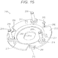
- each of these clutch weights 220 the other end side is coupled to adjacent one of the clutch weights 220 by a coupling spring 222 in a state in which one end side is turnably supported by the swing support pin 214 through the pin slide hole 221.
- the other end side is pulled in the inward direction of the drive plate 210. That is, the clutch weight 220 is supported on the drive plate 210 through each of the swing support pin 214 and the pin slide hole 221 in a state in which the other end side provided with the clutch shoe 223 is swingable relative to the clutch outer 230.
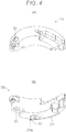
- the protruding body 224 is a component configured to press the clutch weight 220 to the clutch outer 230 side.
- the protruding body 224 is formed to protrude from the surface of the clutch weight 220 facing the drive plate 210. More specifically, the protruding body 224 has a slide portion 224a that is formed at the drive plate 210, faces the guide portion 216, and is configured to slide on such a guide portion 216. As in the guide portion 216, the slide portion 224a is formed to extend inclined to the outer rear side in the rotary drive direction of the drive plate 210.
- the slide portion 224a includes an arc-shaped curved surface projecting in a raised shape toward a guide portion 216 side.
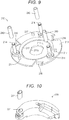
- the clutch outer 230 is a component to be rotatably driven together with the drive shaft 133.
- the clutch outer 230 is formed in such a manner that a metal material is formed into a cup shape covering the outer peripheral surface of the clutch weight 220 from the drive plate 210. That is, the clutch outer 230 has a cylindrical surface 231 configured to friction-contact the clutch shoe 223 of the clutch weight 220 displaced to the outer peripheral side of the drive plate 210.
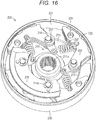
- the pin slide hole 221 is formed with such a length that contact with the swing support pin 214 is avoided in a state in which the clutch weight 220 enters the portion between the guide portion 216 and the clutch outer 230 in the wedge manner. That is, in the pin slide hole 221, a clearance S is ensured between the pin slide hole 221 and the swing support pin 214 even in a state in which the clutch weight 220 enters the portion between the guide portion 216 and the clutch outer 230 in the wedge manner. This prevents interference with entrance of the clutch weight 220 into the portion between the guide portion 216 and the clutch outer 230.
- the pin slide hole 221 is formed as the arc-shaped through-hole. However, it is enough to form the pin slide hole 221 as the long hole allowing backward displacement of the clutch weight 220 in the rotary drive direction of the drive plate 210 in a state (see Fig. 5 ) in which the clutch shoe 223 of the clutch weight 220 is most separated from the cylindrical surface 231 of the clutch outer 230.
- the pin slide hole 221 is not limited to that of the above-described embodiment.
- polyetheretherketone resin PEEK
- polyphenylene sulfide resin PPS
- polyamide-imide resin PAI
- fluorine resin PTFE
- polyimide resin PI
- diallyphthalate resin PDAP
- EP epoxy resin
- SI silicon resin
- the pivot-point-side slide member 240 is formed to have such inner and outer diameters that the pivot-point-side slide member 240 can rotatably slide on each of the swing support pin 214 and the pin slide hole 221, i.e., a dimensional tolerance as a clearance fit for each of the swing support pin 214 and the pin slide hole 221. According to such a configuration, in the centrifugal clutch 200, slide resistance between the swing support pin 214 and the pin slide hole 221 is reduced by the pivot-point-side slide member 240 so that both components can smoothly slide on each other and abrasion of both components can be prevented.
- the pivot-point-side slide member 240 can be made of other materials than the resin material, such as a metal material.
- the pivot-point-side slide member 240 may be made of the same material as that of the swing support pin 214 or the pin slide hole 221, or may be made of a material different from that of the swing support pin 214 or the pin slide hole 221.
- the pivot-point-side slide member 240 is made of a more-easily-abradable material than the material(s) forming the swing support pin 214 and/or the pin slide hole 221, and therefore, abrasion of the swing support pin 214 and/or the pin slide hole 221 can be reduced.
- the pivot-point-side slide member 240 is made of a material (e.g., an aluminum material) having better slidability than that of the material(s) forming the swing support pin 214 and/or the pin slide hole 221, and therefore, the slidability between the swing support pin 214 and the pin slide hole 221 can be improved.
- the pivot-point-side slide member 240 can be also made of a material (e.g., a metal material or a ceramic material) having thermal resistance and abrasion resistance.
- pivot-point-side slide member 240 may be directly provided on the swing support pin 214. As illustrated in Fig. 11 , the pivot-point-side slide member 240 can be also provided at the swing support pin 214 through an auxiliary pivot-point-side slide member 242.
- the auxiliary pivot-point-side slide member 242 is a component provided between the swing support pin 214 and the pivot-point-side slide member 240 to slide these components.
- the auxiliary pivot-point-side slide member 242 is formed as a cylindrical body similar to the pivot-point-side slide member 240.
- the protruding body 224 is formed in a substantially quadrangular columnar shape having the curved slide portion 224a.
- the protruding body 224 can be formed in a circular columnar shape as illustrated in Fig. 12 .
- the slide portion 224a can be also formed in a planar shape.
- the guide portion 216 may be formed as a flat surface parallel with the protruding body 224, or may be formed as an arc-shaped curved surface projecting in a raised shape to the protruding body 224.
- the protruding body 244 is made of a more-easily-abradable material than the material(s) forming the protruding body support pin 243 and/or the guide portion 216, and therefore, abrasion of the protruding body support pin 243 and/or the guide portion 216 can be reduced.
- the protruding body 244 is made of a material (e.g., an aluminum material) having better slidability than that of the material(s) forming the protruding body support pin 243 and/or the guide portion 216, and therefore, slidability between the protruding body support pin 243 and the guide portions 216 can be improved.
- the protruding body 244 can be also made of a material (e.g., a metal material or a ceramic material) having thermal resistance and abrasion resistance.
Landscapes
- Engineering & Computer Science (AREA)
- General Engineering & Computer Science (AREA)
- Mechanical Engineering (AREA)
- One-Way And Automatic Clutches, And Combinations Of Different Clutches (AREA)
- Transmissions By Endless Flexible Members (AREA)
Applications Claiming Priority (2)
| Application Number | Priority Date | Filing Date | Title |
|---|---|---|---|
| JP2018004298 | 2018-01-15 | ||
| PCT/JP2018/039758 WO2019138649A1 (fr) | 2018-01-15 | 2018-10-25 | Embrayage centrifuge |
Publications (2)
| Publication Number | Publication Date |
|---|---|
| EP3742016A1 true EP3742016A1 (fr) | 2020-11-25 |
| EP3742016A4 EP3742016A4 (fr) | 2021-11-03 |
Family
ID=67218692
Family Applications (1)
| Application Number | Title | Priority Date | Filing Date |
|---|---|---|---|
| EP18900175.3A Withdrawn EP3742016A4 (fr) | 2018-01-15 | 2018-10-25 | Embrayage centrifuge |
Country Status (6)
| Country | Link |
|---|---|
| US (1) | US20200370607A1 (fr) |
| EP (1) | EP3742016A4 (fr) |
| JP (1) | JP2019124361A (fr) |
| CA (1) | CA3088103A1 (fr) |
| TW (1) | TWI794356B (fr) |
| WO (1) | WO2019138649A1 (fr) |
Cited By (1)
| Publication number | Priority date | Publication date | Assignee | Title |
|---|---|---|---|---|
| EP3816468A4 (fr) * | 2018-05-11 | 2022-02-09 | Kabushiki Kaisha F.C.C. | Embrayage centrifuge |
Families Citing this family (3)
| Publication number | Priority date | Publication date | Assignee | Title |
|---|---|---|---|---|
| JP6503152B1 (ja) * | 2018-01-15 | 2019-04-17 | 株式会社エフ・シー・シー | 遠心クラッチ |
| JP7045127B2 (ja) * | 2018-05-18 | 2022-03-31 | 株式会社エフ・シー・シー | 遠心クラッチ |
| CN117128257A (zh) * | 2022-05-18 | 2023-11-28 | 米沃奇电动工具公司 | 离合器机构 |
Family Cites Families (14)
| Publication number | Priority date | Publication date | Assignee | Title |
|---|---|---|---|---|
| US2087968A (en) * | 1932-03-14 | 1937-07-27 | Bendix Aviat Corp | Clutch |
| FR819400A (fr) * | 1936-03-20 | 1937-10-15 | Fusion Moteurs A | Perfectionnements apportés aux embrayages, notamment à ceux pour appareils centrifugeurs |
| SE369544B (fr) * | 1973-01-12 | 1974-09-02 | R Johansson | |
| JP3509726B2 (ja) * | 2000-09-06 | 2004-03-22 | 株式会社エフ・シー・シー | 湿式遠心クラッチ用クラッチウエイト及びその製造方法 |
| FR2870304B1 (fr) * | 2004-05-14 | 2007-03-09 | Michel Chabrut | Coupleur entre un arbre moteur de sortie rotatif d'un dispositif de coupe et un organe de coupe rotatif et dispositif de coupe equipe d'un tel coupleur |
| JP4242813B2 (ja) | 2004-07-28 | 2009-03-25 | 株式会社エフ・シー・シー | 遠心クラッチ装置及びその製造方法 |
| JP2007120601A (ja) * | 2005-10-27 | 2007-05-17 | Honda Motor Co Ltd | 遠心クラッチ |
| TW200800715A (en) * | 2006-06-16 | 2008-01-01 | Tuan Huei | A clutch with high brake torque and stable brake |
| JP2009121522A (ja) * | 2007-11-12 | 2009-06-04 | F C C:Kk | 遠心クラッチ装置 |
| TW201432175A (zh) * | 2013-02-04 | 2014-08-16 | Zeng yue hua | 浮設式徑向強制接合之離合器 |
| JP6293560B2 (ja) | 2014-04-11 | 2018-03-14 | 株式会社エフ・シー・シー | 遠心クラッチ |
| JP6590307B2 (ja) * | 2015-06-12 | 2019-10-16 | 株式会社エフ・シー・シー | 遠心クラッチ |
| JP6200474B2 (ja) * | 2015-10-08 | 2017-09-20 | 株式会社エフ・シー・シー | 遠心クラッチ |
| JP6358668B2 (ja) * | 2016-07-15 | 2018-07-18 | 株式会社エフ・シー・シー | 遠心クラッチ |
-
2018
- 2018-10-25 WO PCT/JP2018/039758 patent/WO2019138649A1/fr unknown
- 2018-10-25 CA CA3088103A patent/CA3088103A1/fr not_active Abandoned
- 2018-10-25 US US16/960,824 patent/US20200370607A1/en not_active Abandoned
- 2018-10-25 EP EP18900175.3A patent/EP3742016A4/fr not_active Withdrawn
- 2018-12-07 TW TW107144238A patent/TWI794356B/zh active
-
2019
- 2019-04-03 JP JP2019070966A patent/JP2019124361A/ja active Pending
Cited By (1)
| Publication number | Priority date | Publication date | Assignee | Title |
|---|---|---|---|---|
| EP3816468A4 (fr) * | 2018-05-11 | 2022-02-09 | Kabushiki Kaisha F.C.C. | Embrayage centrifuge |
Also Published As
| Publication number | Publication date |
|---|---|
| US20200370607A1 (en) | 2020-11-26 |
| TW201932729A (zh) | 2019-08-16 |
| WO2019138649A1 (fr) | 2019-07-18 |
| JP2019124361A (ja) | 2019-07-25 |
| EP3742016A4 (fr) | 2021-11-03 |
| TWI794356B (zh) | 2023-03-01 |
| CA3088103A1 (fr) | 2019-07-18 |
Similar Documents
| Publication | Publication Date | Title |
|---|---|---|
| EP3486518B1 (fr) | Embrayage centrifuge | |
| EP3742016A1 (fr) | Embrayage centrifuge | |
| US10760626B2 (en) | Centrifugal clutch | |
| EP3742015B1 (fr) | Embrayage centrifuge | |
| EP3816468B1 (fr) | Embrayage centrifuge | |
| US11346407B2 (en) | Centrifugal clutch | |
| US11415187B2 (en) | Centrifugal clutch | |
| EP3537000B1 (fr) | Embrayage centrifuge | |
| US11255388B2 (en) | Centrifugal clutch | |
| CN111356853B (zh) | 离心离合器 |
Legal Events
| Date | Code | Title | Description |
|---|---|---|---|
| STAA | Information on the status of an ep patent application or granted ep patent |
Free format text: STATUS: THE INTERNATIONAL PUBLICATION HAS BEEN MADE |
|
| PUAI | Public reference made under article 153(3) epc to a published international application that has entered the european phase |
Free format text: ORIGINAL CODE: 0009012 |
|
| STAA | Information on the status of an ep patent application or granted ep patent |
Free format text: STATUS: REQUEST FOR EXAMINATION WAS MADE |
|
| 17P | Request for examination filed |
Effective date: 20200629 |
|
| AK | Designated contracting states |
Kind code of ref document: A1 Designated state(s): AL AT BE BG CH CY CZ DE DK EE ES FI FR GB GR HR HU IE IS IT LI LT LU LV MC MK MT NL NO PL PT RO RS SE SI SK SM TR |
|
| AX | Request for extension of the european patent |
Extension state: BA ME |
|
| DAV | Request for validation of the european patent (deleted) | ||
| DAX | Request for extension of the european patent (deleted) | ||
| A4 | Supplementary search report drawn up and despatched |
Effective date: 20211006 |
|
| RIC1 | Information provided on ipc code assigned before grant |
Ipc: F16D 43/18 20060101AFI20210930BHEP |
|
| STAA | Information on the status of an ep patent application or granted ep patent |
Free format text: STATUS: THE APPLICATION IS DEEMED TO BE WITHDRAWN |
|
| 18D | Application deemed to be withdrawn |
Effective date: 20220503 |