EP3742010A1 - Système et procédé d'assemblage d'un palier de couronne de rotation ayant une précharge prédéterminée - Google Patents
Système et procédé d'assemblage d'un palier de couronne de rotation ayant une précharge prédéterminée Download PDFInfo
- Publication number
- EP3742010A1 EP3742010A1 EP20175478.5A EP20175478A EP3742010A1 EP 3742010 A1 EP3742010 A1 EP 3742010A1 EP 20175478 A EP20175478 A EP 20175478A EP 3742010 A1 EP3742010 A1 EP 3742010A1
- Authority
- EP
- European Patent Office
- Prior art keywords
- slewing ring
- ring bearing
- race
- outer race
- portions
- Prior art date
- Legal status (The legal status is an assumption and is not a legal conclusion. Google has not performed a legal analysis and makes no representation as to the accuracy of the status listed.)
- Granted
Links
- 230000036316 preload Effects 0.000 title claims abstract description 72
- 238000000034 method Methods 0.000 title claims description 48
- 238000000926 separation method Methods 0.000 claims description 16
- 230000008878 coupling Effects 0.000 claims description 7
- 238000010168 coupling process Methods 0.000 claims description 7
- 238000005859 coupling reaction Methods 0.000 claims description 7
- 125000006850 spacer group Chemical group 0.000 claims description 5
- 238000005096 rolling process Methods 0.000 description 11
- 230000008901 benefit Effects 0.000 description 6
- 230000007246 mechanism Effects 0.000 description 5
- 230000007423 decrease Effects 0.000 description 2
- 230000001627 detrimental effect Effects 0.000 description 2
- 238000010586 diagram Methods 0.000 description 2
- 230000004048 modification Effects 0.000 description 2
- 238000012986 modification Methods 0.000 description 2
- 230000009467 reduction Effects 0.000 description 2
- 230000003466 anti-cipated effect Effects 0.000 description 1
- 238000005452 bending Methods 0.000 description 1
- 230000008859 change Effects 0.000 description 1
- 238000010894 electron beam technology Methods 0.000 description 1
- 230000006870 function Effects 0.000 description 1
- 238000010438 heat treatment Methods 0.000 description 1
- 238000007373 indentation Methods 0.000 description 1
- 230000006698 induction Effects 0.000 description 1
- 238000005121 nitriding Methods 0.000 description 1
- 230000008569 process Effects 0.000 description 1
- 230000004044 response Effects 0.000 description 1
Images


Classifications
-
- F—MECHANICAL ENGINEERING; LIGHTING; HEATING; WEAPONS; BLASTING
- F16—ENGINEERING ELEMENTS AND UNITS; GENERAL MEASURES FOR PRODUCING AND MAINTAINING EFFECTIVE FUNCTIONING OF MACHINES OR INSTALLATIONS; THERMAL INSULATION IN GENERAL
- F16C—SHAFTS; FLEXIBLE SHAFTS; ELEMENTS OR CRANKSHAFT MECHANISMS; ROTARY BODIES OTHER THAN GEARING ELEMENTS; BEARINGS
- F16C19/00—Bearings with rolling contact, for exclusively rotary movement
- F16C19/02—Bearings with rolling contact, for exclusively rotary movement with bearing balls essentially of the same size in one or more circular rows
- F16C19/14—Bearings with rolling contact, for exclusively rotary movement with bearing balls essentially of the same size in one or more circular rows for both radial and axial load
- F16C19/18—Bearings with rolling contact, for exclusively rotary movement with bearing balls essentially of the same size in one or more circular rows for both radial and axial load with two or more rows of balls
- F16C19/181—Bearings with rolling contact, for exclusively rotary movement with bearing balls essentially of the same size in one or more circular rows for both radial and axial load with two or more rows of balls with angular contact
- F16C19/183—Bearings with rolling contact, for exclusively rotary movement with bearing balls essentially of the same size in one or more circular rows for both radial and axial load with two or more rows of balls with angular contact with two rows at opposite angles
-
- F—MECHANICAL ENGINEERING; LIGHTING; HEATING; WEAPONS; BLASTING
- F16—ENGINEERING ELEMENTS AND UNITS; GENERAL MEASURES FOR PRODUCING AND MAINTAINING EFFECTIVE FUNCTIONING OF MACHINES OR INSTALLATIONS; THERMAL INSULATION IN GENERAL
- F16C—SHAFTS; FLEXIBLE SHAFTS; ELEMENTS OR CRANKSHAFT MECHANISMS; ROTARY BODIES OTHER THAN GEARING ELEMENTS; BEARINGS
- F16C25/00—Bearings for exclusively rotary movement adjustable for wear or play
- F16C25/06—Ball or roller bearings
- F16C25/08—Ball or roller bearings self-adjusting
- F16C25/083—Ball or roller bearings self-adjusting with resilient means acting axially on a race ring to preload the bearing
-
- F—MECHANICAL ENGINEERING; LIGHTING; HEATING; WEAPONS; BLASTING
- F03—MACHINES OR ENGINES FOR LIQUIDS; WIND, SPRING, OR WEIGHT MOTORS; PRODUCING MECHANICAL POWER OR A REACTIVE PROPULSIVE THRUST, NOT OTHERWISE PROVIDED FOR
- F03D—WIND MOTORS
- F03D80/00—Details, components or accessories not provided for in groups F03D1/00 - F03D17/00
- F03D80/70—Bearing or lubricating arrangements
-
- F—MECHANICAL ENGINEERING; LIGHTING; HEATING; WEAPONS; BLASTING
- F16—ENGINEERING ELEMENTS AND UNITS; GENERAL MEASURES FOR PRODUCING AND MAINTAINING EFFECTIVE FUNCTIONING OF MACHINES OR INSTALLATIONS; THERMAL INSULATION IN GENERAL
- F16C—SHAFTS; FLEXIBLE SHAFTS; ELEMENTS OR CRANKSHAFT MECHANISMS; ROTARY BODIES OTHER THAN GEARING ELEMENTS; BEARINGS
- F16C19/00—Bearings with rolling contact, for exclusively rotary movement
- F16C19/02—Bearings with rolling contact, for exclusively rotary movement with bearing balls essentially of the same size in one or more circular rows
- F16C19/04—Bearings with rolling contact, for exclusively rotary movement with bearing balls essentially of the same size in one or more circular rows for radial load mainly
- F16C19/08—Bearings with rolling contact, for exclusively rotary movement with bearing balls essentially of the same size in one or more circular rows for radial load mainly with two or more rows of balls
-
- F—MECHANICAL ENGINEERING; LIGHTING; HEATING; WEAPONS; BLASTING
- F16—ENGINEERING ELEMENTS AND UNITS; GENERAL MEASURES FOR PRODUCING AND MAINTAINING EFFECTIVE FUNCTIONING OF MACHINES OR INSTALLATIONS; THERMAL INSULATION IN GENERAL
- F16C—SHAFTS; FLEXIBLE SHAFTS; ELEMENTS OR CRANKSHAFT MECHANISMS; ROTARY BODIES OTHER THAN GEARING ELEMENTS; BEARINGS
- F16C33/00—Parts of bearings; Special methods for making bearings or parts thereof
- F16C33/30—Parts of ball or roller bearings
- F16C33/58—Raceways; Race rings
- F16C33/60—Raceways; Race rings divided or split, e.g. comprising two juxtaposed rings
-
- F—MECHANICAL ENGINEERING; LIGHTING; HEATING; WEAPONS; BLASTING
- F16—ENGINEERING ELEMENTS AND UNITS; GENERAL MEASURES FOR PRODUCING AND MAINTAINING EFFECTIVE FUNCTIONING OF MACHINES OR INSTALLATIONS; THERMAL INSULATION IN GENERAL
- F16C—SHAFTS; FLEXIBLE SHAFTS; ELEMENTS OR CRANKSHAFT MECHANISMS; ROTARY BODIES OTHER THAN GEARING ELEMENTS; BEARINGS
- F16C43/00—Assembling bearings
- F16C43/04—Assembling rolling-contact bearings
-
- F—MECHANICAL ENGINEERING; LIGHTING; HEATING; WEAPONS; BLASTING
- F05—INDEXING SCHEMES RELATING TO ENGINES OR PUMPS IN VARIOUS SUBCLASSES OF CLASSES F01-F04
- F05B—INDEXING SCHEME RELATING TO WIND, SPRING, WEIGHT, INERTIA OR LIKE MOTORS, TO MACHINES OR ENGINES FOR LIQUIDS COVERED BY SUBCLASSES F03B, F03D AND F03G
- F05B2240/00—Components
- F05B2240/50—Bearings
-
- F—MECHANICAL ENGINEERING; LIGHTING; HEATING; WEAPONS; BLASTING
- F16—ENGINEERING ELEMENTS AND UNITS; GENERAL MEASURES FOR PRODUCING AND MAINTAINING EFFECTIVE FUNCTIONING OF MACHINES OR INSTALLATIONS; THERMAL INSULATION IN GENERAL
- F16C—SHAFTS; FLEXIBLE SHAFTS; ELEMENTS OR CRANKSHAFT MECHANISMS; ROTARY BODIES OTHER THAN GEARING ELEMENTS; BEARINGS
- F16C2226/00—Joining parts; Fastening; Assembling or mounting parts
- F16C2226/50—Positive connections
- F16C2226/60—Positive connections with threaded parts, e.g. bolt and nut connections
-
- F—MECHANICAL ENGINEERING; LIGHTING; HEATING; WEAPONS; BLASTING
- F16—ENGINEERING ELEMENTS AND UNITS; GENERAL MEASURES FOR PRODUCING AND MAINTAINING EFFECTIVE FUNCTIONING OF MACHINES OR INSTALLATIONS; THERMAL INSULATION IN GENERAL
- F16C—SHAFTS; FLEXIBLE SHAFTS; ELEMENTS OR CRANKSHAFT MECHANISMS; ROTARY BODIES OTHER THAN GEARING ELEMENTS; BEARINGS
- F16C2229/00—Setting preload
-
- F—MECHANICAL ENGINEERING; LIGHTING; HEATING; WEAPONS; BLASTING
- F16—ENGINEERING ELEMENTS AND UNITS; GENERAL MEASURES FOR PRODUCING AND MAINTAINING EFFECTIVE FUNCTIONING OF MACHINES OR INSTALLATIONS; THERMAL INSULATION IN GENERAL
- F16C—SHAFTS; FLEXIBLE SHAFTS; ELEMENTS OR CRANKSHAFT MECHANISMS; ROTARY BODIES OTHER THAN GEARING ELEMENTS; BEARINGS
- F16C2360/00—Engines or pumps
- F16C2360/31—Wind motors
-
- Y—GENERAL TAGGING OF NEW TECHNOLOGICAL DEVELOPMENTS; GENERAL TAGGING OF CROSS-SECTIONAL TECHNOLOGIES SPANNING OVER SEVERAL SECTIONS OF THE IPC; TECHNICAL SUBJECTS COVERED BY FORMER USPC CROSS-REFERENCE ART COLLECTIONS [XRACs] AND DIGESTS
- Y02—TECHNOLOGIES OR APPLICATIONS FOR MITIGATION OR ADAPTATION AGAINST CLIMATE CHANGE
- Y02E—REDUCTION OF GREENHOUSE GAS [GHG] EMISSIONS, RELATED TO ENERGY GENERATION, TRANSMISSION OR DISTRIBUTION
- Y02E10/00—Energy generation through renewable energy sources
- Y02E10/70—Wind energy
- Y02E10/72—Wind turbines with rotation axis in wind direction
Definitions
- the present disclosure relates in general to wind turbines, and more particularly to systems and methods for assembling a slewing ring bearing with a predetermined preload.
- Wind power is considered one of the cleanest, most environmentally friendly energy sources presently available, and wind turbines have gained increased attention in this regard.
- a modern wind turbine typically includes a tower, a generator, a gearbox, a nacelle, and one or more rotor blades.
- the nacelle includes a rotor assembly coupled to the gearbox and to the generator.
- the rotor assembly and the gearbox are mounted on a bedplate support frame located within the nacelle. More specifically, in many wind turbines, the gearbox is mounted to the bedplate via one or more torque arms or arms.
- the one or more rotor blades capture kinetic energy of wind using known airfoil principles.
- the rotor blades transmit the kinetic energy in the form of rotational energy so as to turn a shaft coupling the rotor blades to a gearbox, or if a gearbox is not used, directly to the generator.
- the generator then converts the mechanical energy to electrical energy that may be deployed to a utility grid.
- wind turbines may include various slewing ring bearings to facilitate rotation of their various components.
- slewing ring bearings may include a pitch bearing and a yaw bearing.
- yaw bearings are configured to rotate the nacelle with respect to the tower as a function of incoming wind.
- pitch bearings are arranged between a blade root of the rotor blades and the hub to facilitate rotation of the rotor blades with respect to the incoming wind.
- Such bearings generally include an outer race, an inner race rotatable relative to the outer race, and a plurality of rolling elements therebetween.
- the bearings are typically assembled in such a way that a certain amount of clearance exists between the rolling elements and the raceways. This clearance is known as “play” or “slop” and may allow the races to misalign or the rolling elements to slide, rather than roll.
- play or "slop” and may allow the races to misalign or the rolling elements to slide, rather than roll.
- the performance of the bearing generally decreases as the amount of play increases. In particular, an increase in the amount of play, typically, reduces the amount of load which may be applied to the bearing without detrimental effects.
- a known method for limiting the detrimental effects of play is to apply a bearing preload.
- the purpose of the preload is to reduce or eliminate the amount of play in the bearing by subjecting the rolling elements to an axial load in advance of receiving the operating load.
- the present disclosure is directed to a slewing ring bearing.
- the slewing ring bearing may have an outer race and an inner race rotatable relative to the outer race.
- the slewing ring bearing may also include a plurality of roller elements arranged between one or more raceways defined by the inner and/or the outer races.
- At least one of the outer race or the inner race may be split into a first portion and a separate, second portion.
- the first and second portions of at least one of the outer race or the inner race may be coupled together via a threaded interface therebetween so as to establish a predetermined preload for the slewing ring bearing.
- the one or more raceways may be asymmetric raceways.
- the plurality of roller elements may also include a first row of roller elements and a second row of roller elements.
- the first and second rows of roller elements define first and second contact angles, respectively. The first and second contact angles may be established by a design contact angle of the asymmetric raceway(s).
- the magnitude of the predetermined preload may be established by a separation between the first and second portions of at least one of the outer race or the inner race along a preload interface.
- the magnitude of the predetermined preload may define a bearing stiffness.
- the predetermined preload may be a maximal-predetermined preload when the first and second portions of the outer race and/or the inner race are in contact along the preload interface.
- the slewing ring bearing may include a spacer positioned between the first and second portions of the outer race and/or the inner race so as to establish a mechanical limit between the first and second portions along the preload interface.
- the threaded interface may be located in a lower-stress region of the outer or inner race having a stress concentration which is less than 95% of a maximal stress of the respective race.
- the slewing ring bearing may be at least one of a pitch bearing or a yaw bearing of a wind turbine.
- the present disclosure is directed to a method for assembling a slewing ring bearing with a predetermined preload.
- the method may include providing an outer race of the slewing ring bearing and arranging an inner race of the slewing ring bearing radially inward of the outer race. At least one of the outer race or the inner race may be split into a first portion and a separate, second portion.
- the method may include coupling the first and second portions of at least one of the outer race or the inner race together by engaging a threaded interface between the first and second portions so as to provide the predetermined preload to the slewing ring bearing. Additionally, the method may also include placing a plurality of roller elements within one or more raceways defined by the inner race and the outer race.
- the method may also include ensuring the predetermined preload is within a specified design limit for the slewing ring bearing.
- the method may include rotating at least one of the first portion or the second portion with respect to the other so as to advance at least one of the first portion or the second portion along the threaded interface so as to reduce a separation between the first and second portions.
- rotating the first portion and/or the second portion with respect to the other may also include rotating the first portion and/or the second portion at least 45° but less than or equal to 1440 °.
- rotating the first portion and/or the second portion with respect to the other may also include engaging a toothed gear of the first portion and/or the second portion with a pinion drive so as to apply a radial torque thereto.
- the method may also include establishing first and second contact angles, respectively, for the first and second rows of roller elements. In an additional embodiment, the method may also include establishing a contact stress between the first and second row of roller elements and the one or more raceways of less than or equal to two (2) gigapascals (GPa).
- GPa gigapascals
- the present disclosure is directed to a wind turbine.
- the wind turbine may include a tower, a nacelle mounted atop the tower, and a rotor mounted to the nacelle.
- the rotor may include a rotatable hub having one or more rotor blades secured thereto.
- the wind turbine may include at least one slewing ring bearing arranged between at least one of the tower and the nacelle or the hub and one of the one or more rotor blades.
- the slewing ring bearing may include an outer race and an inner race rotatable relative to the outer race. At least one of the outer race or the inner race may be split into a first portion and a separate, second portion.
- the slewing ring bearing may also include a plurality of roller elements arranged between one or more raceways defined by the inner and outer races.
- the first and second portions of the outer race and/or the inner race may be coupled together via a threaded interface therebetween so as to establish a predetermined preload for the slewing ring bearing.
- the present disclosure is directed to a slewing ring bearing with a predetermined preload.
- the slewing ring bearing may include an outer race and an inner race rotatable relative to the outer race. At least one of the outer race or the inner race may include a threaded interface which joins a first portion and a separate, second portion thereof.
- a plurality of roller elements may be arranged between one or more raceways defined by the inner and outer races.
- a contact stress (e.g., a preload) between the roller elements and the raceways may be established by fixing either the first portion or the second portion and rotating the other so as to engage the threaded portion and draw the first and second portions together. The magnitude of the contact stress may be determined by a distance between the first and second portions.
- the contact stress, or preload may be at a maximum when the first and second portions are in contact along a preload interface.
- the magnitude of the stress may increase up to a maximum (i.e. no more torque may be applied).
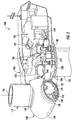
- FIG. 1 illustrates a perspective view of one embodiment of a wind turbine 100 according to the present disclosure.
- the wind turbine 100 generally includes a tower 102 extending from a support surface 104, a nacelle 106 mounted on the tower 102, and a rotor 108 coupled to the nacelle 106.
- the rotor 108 includes a rotatable hub 110 and at least one rotor blade 112 coupled to and extending outwardly from the hub 110.
- the rotor 108 includes three rotor blades 112.
- the rotor 108 may include more or less than three rotor blades 112.
- Each rotor blade 112 may be spaced about the hub 110 to facilitate rotating the rotor 108 to enable kinetic energy to be transferred from the wind into usable mechanical energy, and subsequently, electrical energy.
- the hub 110 may be rotatably coupled to an electric generator 118 ( FIG. 2 ) positioned within the nacelle 106 to permit electrical energy to be produced.
- the generator 118 may be coupled to the rotor 108 for producing electrical power from the rotational energy generated by the rotor 108.
- the rotor 108 may include a rotor shaft 122 coupled to the hub 110 for rotation therewith.
- the rotor shaft 122 may be rotatably supported by a main bearing 144.
- the rotor shaft 122 may, in turn, be rotatably coupled to a generator shaft 124 of the generator 118 through a gearbox 126 connected to a bedplate support frame 136 by one or more torque arms 142.
- the rotor shaft 122 may provide a low speed, high torque input to the gearbox 126 in response to rotation of the rotor blades 112 and the hub 110.
- the gearbox 126 may then be configured to convert the low speed, high torque input to a high speed, low torque output to drive the generator shaft 124 and, thus, the generator 118.
- Each rotor blade 112 may also include a pitch adjustment mechanism 120 configured to rotate each rotor blade 112 about its pitch axis 116.
- each pitch adjustment mechanism 120 may include a pitch drive motor 128 (e.g., any suitable electric, hydraulic, or pneumatic motor), a pitch drive gearbox 130, and a pitch drive pinion 132.
- the pitch drive motor 128 may be coupled to the pitch drive gearbox 130 so that the pitch drive motor 128 imparts mechanical force to the pitch drive gearbox 130.
- the pitch drive gearbox 130 may be coupled to the pitch drive pinion 132 for rotation therewith.
- the pitch drive pinion 132 may, in turn, be in rotational engagement with a pitch bearing 134 coupled between the hub 110 and a corresponding rotor blade 112 such that rotation of the pitch drive pinion 132 causes rotation of the pitch bearing 134.
- rotation of the pitch drive motor 128 drives the pitch drive gearbox 130 and the pitch drive pinion 132, thereby rotating the pitch bearing 134 and the rotor blade 112 about the pitch axis 116.
- the wind turbine 100 may include one or more yaw drive mechanisms 138being configured to change the angle of the nacelle 106 relative to the wind (e.g., by engaging a yaw bearing 140 of the wind turbine 100).
- FIG. 3 a cross-sectional view of one embodiment of an interface between the rotor blade 112 and the hub 110 of the wind turbine 100 is depicted according to the present disclosure.
- the rotor blade 112 may be secured to the hub 110 via one or more barrel nuts 146 mounted within a portion of a blade root of the rotor blade 112.
- a plurality of root bolts 148 may be coupled to, and extend from, the barrel nuts 146, and may be used to couple the blade root of the rotor blade 112 to the hub 110 through the pitch bearing 134.
- the pitch bearing 134 may be a slewing ring bearing 200.
- the pitch bearing 134 may include an outer bearing race 202, an inner bearing race 204, and a plurality of roller elements 206 (e.g., ball bearings) disposed between the outer and inner races 202, 204.
- the outer race 202 may be configured to be mounted to the hub 110 using a plurality of hub bolts 150 and/or other suitable fastening mechanisms.
- the inner race 204 may be configured to be mounted to the rotor blade 112 using the plurality of root bolts 148.
- the inner race 204 may be configured to be rotated relative to the outer race 202 via the roller elements 206 to allow the pitch angle of each rotor blade 112 to be adjusted. As shown in FIGS. 2 and 3 , such relative rotation of the outer and inner races 202, 204 may be achieved using the pitch adjustment mechanism 120 described herein.
- a plurality of gear teeth 208 may be formed along the inner circumference 210 of the inner race 204.
- the gear teeth 208 may be configured to mesh with corresponding gear teeth 152 formed on the pitch drive pinion 132.
- rotation of the pitch drive pinion 132 results in rotation of the inner race 204 relative to the outer race 202 and, thus, rotation of the rotor blade 112 relative to the hub 110.
- the outer race 202 may be rotated relative to the inner race 204.
- a portion of the outer race 202 may be formed with a plurality of gear teeth 208 so as to form a toothed gear 214.
- the slewing ring bearing 200 may be configured in various embodiments as a pitch bearing 134 or a yaw bearing 140 of the wind turbine 100.
- the inner and outer races 202, 204 may define one or more raceways 212.
- the plurality of roller elements 206 may be arranged between the raceways 212 defined by the inner and outer races 202, 204.
- the plurality of roller elements 206 may be any suitable rolling element, such as ball bearings, spherical rollers, cylindrical rollers, tapered rollers, or needles.
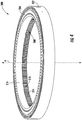
- the slewing ring bearing 200 may be configured as a split-ring bearing.
- the outer race 202 and/or the inner race 204 may be split into a first portion 216 and a separate, second portion 218.
- the first and second portions 216, 218 may be ring-shaped and oriented on axially-aligned planes perpendicular to an axis of rotation (A).
- the first portion 216 and the second portion 218 may be coupled together via a threaded interface 220.
- the threaded interface 220 may include a plurality of corresponding circumferential threads 222 formed in opposing portions of the first and second portions 216, 218.
- the threaded interface 220 may be configured to facilitate drawing together of the first and second portions 216, 218.
- the threaded interface 220 may form an interrupted screw.
- the corresponding circumferential threads 222 may be interrupted so as to facilitate coupling of the first and second portions 216, 218 via a 45 degree rotation on one relative to the other.
- the threaded interface 220 may be configured to minimize the likelihood of a bearing failure due to a concentration of stresses surrounding the threaded interface 220.
- the threaded interface 220 may be located in a lower-stress region 224 of the slewing ring bearing 200.
- the "lower-stress region” generally refers to a region of the respective inner or outer race 202, 204 having the first and second portions 216, 218 wherein an anticipated stress concentration is less than 95% of a maximal stress concentration of the respective race. It should be appreciated that positioning the threaded interface 220 in the lower-stress region 224 may make the slewing ring bearing 200 less prone to failure than if the threaded interface 220 were placed in an area of a higher stress concentration.
- the threaded interface 220 may result in a stress concentration or stress riser.
- the threaded interface 220 may, however, be configured so as to have a stress concentration factor (Kt) of less than or equal to 4.0. Accordingly, the Kt may define a maximum acceptable increase in stress in the threaded interface 220. For example, if the localized stress concentration of a split-ring slewing ring bearing without a threaded interface were 5 mega pascals (MPa), then in an embodiment wherein the threaded interface 220 has a Kt of 4.0, the resultant stress concentration may not exceed 10 MPa.
- the plurality of threads 222 may be formed so as to eliminate sharp corners. For example, as shown, the plurality of threads 222 may be formed as arcuate threads.
- the slewing ring bearing 200 may be formed as an angular contact bearing with one or more raceways 212 which are asymmetric raceways.
- a line of contact connecting the centers of curvatures of opposing raceways is generally oriented either parallel with, or perpendicular to the axis of rotation.
- the raceway will typically have horizontal or vertical symmetry about the center of curvature.
- the centers of curvature 226 of the opposing raceways 212 may be placed at reciprocal angles along a 90° arc between parallel with and perpendicular to the axis of rotation (A). Because of the placement of the centers of curvature 226 at the reciprocal angles, the raceways 212 may lack horizontal and/or vertical symmetry about the centers of curvature 226.
- the inner race 204 and/or the outer race 202 may define a first portion of a first raceway 230 and a first portion of a second raceway 232.
- the other of the inner race 204 or the outer race 202 may define a second portion of the first raceway 230 and a second portion of the second raceway 232.
- the second portion of the first raceway 230 and the second portion of the second raceway 232 may be defined by the first and second portions 216, 218 of the inner or outer race 204, 202.
- the first raceway 230 and the second raceway 232 may form parallel raceways within the slewing ring bearing 200.
- the roller elements 206 may include a first row of roller elements 234 and a second row of roller elements 236 positioned within the respective first and second raceways 230, 232.
- the raceways 212 of the slewing ring bearing 200 may be surface hardened. Surface hardening the raceways 212 may make the raceways 212 more resistant to wear and indentation.
- the raceways 212 may be hardened using known thermal or mechanical hardening processes, such as induction heating, laser hardening, nitriding, peening, vibration hardening, burnishing, or electron beam hardening. It should be appreciated that the threaded interface 220 should be located in a region of the slewing ring bearing 200 which is not surface hardened.
- the placement of the centers of curvature 226 of the opposing raceways 212 may define a design contact angle ( ⁇ ) for the raceways 212.
- the employment of the design contact angle ( ⁇ ) of an angular contact bearing may increase the ability of slewing ring bearing 200 to support a combined axial and radial load.
- the design contact angle ( ⁇ ) is established by the geometry of the raceways 212. It should be appreciated that the capacity of the slewing ring bearing 200 may be maximized when the rolling elements 206 are in contact with the raceways 212 along the design contact angle ( ⁇ ). It should be further appreciated that the rolling elements 206 contacting the raceways 212 at angles other than the design contact angle ( ⁇ ) may reduce the ability of slewing ring bearing 200 to support either an axial or radial load, such as a bending moment.
- the rolling elements 206 may establish a contact patch, or contact ellipse 238, in a region where the rolling element 206 contacts the raceway 212.
- a contact axis (CA) may be drawn through the center of the rolling element 206 and between opposing contact patches 238.
- the contact axis (CA) may define a contact angle ( ⁇ 1 ) relative to a plane either parallel or perpendicular with the axis of rotation (A). Due to clearances, or slop, between the components of the slewing ring bearing 200, the contact angle ( ⁇ 1 ) under load may be different than the design contact angle ( ⁇ ). It should be appreciated that the establishment of the contact angle ( ⁇ 1 ) which is different than the design contact angle ( ⁇ ) may reduce the load-carrying capacity of the slewing ring bearing 200.
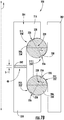
- the slewing ring bearing 200 may, in an embodiment, be subjected to a predetermined preload. As depicted in FIGS. 6 , 7A and 7B , the threaded interface 220 may facilitate the establishment of the predetermined preload for the slewing ring bearing 200. Further, in an embodiment, advancing one of the first or second portions 216, 218 toward the other along the threaded interface 220 may reduce a separation (S) along a preload interface 240. This reduction in the separation (S) may result in establishment of a contact stress between the rolling elements 206 and the raceways 212.
- the contact stress may be less than or equal to 2.5 GPa or may be less than or equal to 2 GPa.
- the contact stress may also, for example, be greater than or equal to 1.5 GPa or greater than or equal to 1.75 GPa.
- the contact stress may be considered to be the magnitude of the predetermined preload.
- the application of the preload and the establishment of the contact angle ( ⁇ 1 ) may define a desired bearing stiffness.
- the magnitude of the predetermined preload may be established by the separation (S).
- the predetermined preload may be a maximal-predetermined preload and the bearing stiffness may be a maximal stiffness.
- the predetermined preload may be a value less than the maximal-predetermined preload such that the bearing stiffness may be reduced. In an embodiment, as shown in FIG.
- this reduction in the predetermined preload and corresponding bearing stiffness may be achieved through the inclusion of a spacer 242 positioned between the first and second portions 216, 218 of at least one of the outer or inner races 202, 204.
- the spacer 242 may establish a mechanical limit between the first and second portions 216, 218 along the preload interface 240.
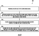
- FIG. 8 a flow diagram of one embodiment of a method 300 of assembling a slewing ring bearing with a predetermined preload is illustrated.
- the method 300 may be implemented using, for instance, the slewing ring bearing 200 discussed above with reference to FIGS. 3-7B .
- FIG. 8 depicts steps performed in a particular order for purposes of illustration and discussion. Those of ordinary skill in the art, using the disclosures provided herein, will understand that various steps of the method 300 or any of the other methods disclosed herein may be adapted, modified, rearranged, performed simultaneously or modified in various ways without deviating from the scope of the present disclosure.
- the method 300 includes providing an outer race of the slewing ring bearing.
- the method 300 includes arranging an inner race of the slewing ring bearing radially inward of the outer race. At least one of the outer race or the inner race being split into a first portion and a separate second portion.
- the method 300 includes placing a plurality of roller elements within one or more raceways defined by at least one of the inner race and or the outer race.
- the method 300 includes coupling the first and second portions of at least one of the outer race or the inner race together by engaging a threaded interface between the first and second portions so as to provide the predetermined preload to the slewing ring bearing.
- the method 300 may also, in accordance with the present disclosure, include ensuring the predetermined preload is within a specified design limit for the slewing ring bearing by performing a torque test on the assembled slewing ring bearing.
- the method 300 may also include rotating at least one of the first portion or the second portion with respect to the other so as to advance at least one of the first portion or the second portion along the threaded interface and reduce a separation between the first and second portions.
- rotating at least one of the first portion or the second portion with respect to the other may include rotating the first portion or the second portion at least 45° but less than or equal to 1440°.
- rotating at least one of the first portion or the second portion with respect to the other may include engaging a toothed gear of at least one of the first portion or the second portion with a pinion drive so as to apply a radial torque thereto.
- the method 300 may also include establishing first and second contact angles, respectively, for the first and second row of roller elements. In yet another embodiment, the method 300 may also include establishing a contact stress between the first and second rows of roller elements and the one or more raceways of less than or equal to 2 GPa.
Landscapes
- Engineering & Computer Science (AREA)
- General Engineering & Computer Science (AREA)
- Mechanical Engineering (AREA)
- Life Sciences & Earth Sciences (AREA)
- Sustainable Development (AREA)
- Sustainable Energy (AREA)
- Chemical & Material Sciences (AREA)
- Combustion & Propulsion (AREA)
- Rolling Contact Bearings (AREA)
Applications Claiming Priority (1)
| Application Number | Priority Date | Filing Date | Title |
|---|---|---|---|
| US16/419,552 US10794422B1 (en) | 2019-05-22 | 2019-05-22 | System and method for assembling a slewing ring bearing with a predetermined preload |
Publications (2)
| Publication Number | Publication Date |
|---|---|
| EP3742010A1 true EP3742010A1 (fr) | 2020-11-25 |
| EP3742010B1 EP3742010B1 (fr) | 2022-09-14 |
Family
ID=70779526
Family Applications (1)
| Application Number | Title | Priority Date | Filing Date |
|---|---|---|---|
| EP20175478.5A Active EP3742010B1 (fr) | 2019-05-22 | 2020-05-19 | Éolienne avec un palier couronne de rotation et procédé d'assemblage d'un palier de couronne de rotation ayant une précharge prédéterminée |
Country Status (4)
| Country | Link |
|---|---|
| US (1) | US10794422B1 (fr) |
| EP (1) | EP3742010B1 (fr) |
| DK (1) | DK3742010T3 (fr) |
| ES (1) | ES2933289T3 (fr) |
Families Citing this family (3)
| Publication number | Priority date | Publication date | Assignee | Title |
|---|---|---|---|---|
| DE102018112017B3 (de) * | 2018-05-18 | 2019-05-23 | Ibrahim Muhamad | Drehverbindung für ein Rotorblatt einer Windenergieanlage |
| CN113392544B (zh) * | 2021-05-28 | 2022-08-26 | 东北林业大学 | 一种基于变形协调理论的行星螺纹滚柱轴承接触载荷计算方法 |
| US11725698B1 (en) * | 2022-05-20 | 2023-08-15 | General Electric Renovables Espana, S.L. | Method for manufacturing slewing ring bearing components having an integral stiffener |
Citations (4)
| Publication number | Priority date | Publication date | Assignee | Title |
|---|---|---|---|---|
| US20070116394A1 (en) * | 2005-11-22 | 2007-05-24 | Thyssenkrupp - Rotek, Inc. | Slewing ring having improved inner race construction |
| DE102007013164A1 (de) * | 2007-03-20 | 2008-09-25 | Schaeffler Kg | Wälzlager mit einer Bremseinrichtung |
| JP2009275792A (ja) * | 2008-05-14 | 2009-11-26 | Ntn Corp | 転がり軸受 |
| WO2013100285A1 (fr) * | 2011-12-26 | 2013-07-04 | 주식회사 일진글로벌 | Structure intégrée de roulement de roue |
Family Cites Families (17)
| Publication number | Priority date | Publication date | Assignee | Title |
|---|---|---|---|---|
| US3651550A (en) * | 1970-08-19 | 1972-03-28 | Us Air Force | Method of preloading a bearing |
| US4400042A (en) * | 1980-10-14 | 1983-08-23 | Keystone Engineering Company | High performance low torque anti-friction bearing assembly |
| US5090852A (en) * | 1984-10-24 | 1992-02-25 | Huck Manufacturing Company | High strength fastener and method |
| US4657412A (en) | 1985-03-25 | 1987-04-14 | The Torrington Company | Variable preload bearing assembly |
| US5376200A (en) * | 1993-08-30 | 1994-12-27 | General Dynamics Corporation | Method for manufacturing an integral threaded connection for a composite tank |
| JP2000120811A (ja) * | 1998-08-12 | 2000-04-28 | Teijin Seiki Co Ltd | 撓み噛み合い式減速機 |
| DE102007019482A1 (de) * | 2007-04-25 | 2008-11-06 | Schaeffler Kg | Mehrreihiges Großwälzlager, insbesondere Axial-Radiallager zur Hauptlagerung der Rotorwelle einer Windkraftanlage |
| DE102007041508A1 (de) * | 2007-08-31 | 2009-03-05 | Schaeffler Kg | Rotorlagerung für eine Windenergieanlage |
| DE102009025516A1 (de) | 2009-06-19 | 2010-12-23 | Schaeffler Technologies Gmbh & Co. Kg | Axial-Schrägwälzlager, insbesondere zur Rundtischlagerung an Werkzeugmaschinen sowie Verfahren zur Montage eines solchen Axial-Schrägwälzlagers |
| DE102009034012B4 (de) * | 2009-07-21 | 2011-09-29 | Aktiebolaget Skf | Verfahren und Vorrichtung zum axialen Sichern eines Maschinenelements |
| GB0916189D0 (en) * | 2009-09-15 | 2009-10-28 | Ricardo Uk Ltd | Bearing for wind turbine |
| DE102011085258A1 (de) * | 2011-10-26 | 2013-05-02 | Aktiebolaget Skf | Lagerring, Lagerringsegment, Lager und Verfahren zur Einstellung einer Vorspannung eines Wälzlagers |
| WO2013107518A1 (fr) * | 2012-01-20 | 2013-07-25 | Aktiebolaget Skf | Unité de palier à entraînement par engrenage |
| JP6180723B2 (ja) * | 2012-11-05 | 2017-08-16 | Ntn株式会社 | 複列転がり軸受 |
| DE102013215962A1 (de) | 2013-08-13 | 2015-03-12 | Schaeffler Technologies AG & Co. KG | Rundtischlager |
| JP2016061317A (ja) * | 2014-09-16 | 2016-04-25 | Ntn株式会社 | Ctスキャナ装置用複列アンギュラ玉軸受 |
| US20180080498A1 (en) * | 2016-09-16 | 2018-03-22 | Schaeffler Technologies AG & Co. KG | Pre-set rolling element bearing |
-
2019
- 2019-05-22 US US16/419,552 patent/US10794422B1/en active Active
-
2020
- 2020-05-19 DK DK20175478.5T patent/DK3742010T3/da active
- 2020-05-19 EP EP20175478.5A patent/EP3742010B1/fr active Active
- 2020-05-19 ES ES20175478T patent/ES2933289T3/es active Active
Patent Citations (4)
| Publication number | Priority date | Publication date | Assignee | Title |
|---|---|---|---|---|
| US20070116394A1 (en) * | 2005-11-22 | 2007-05-24 | Thyssenkrupp - Rotek, Inc. | Slewing ring having improved inner race construction |
| DE102007013164A1 (de) * | 2007-03-20 | 2008-09-25 | Schaeffler Kg | Wälzlager mit einer Bremseinrichtung |
| JP2009275792A (ja) * | 2008-05-14 | 2009-11-26 | Ntn Corp | 転がり軸受 |
| WO2013100285A1 (fr) * | 2011-12-26 | 2013-07-04 | 주식회사 일진글로벌 | Structure intégrée de roulement de roue |
Also Published As
| Publication number | Publication date |
|---|---|
| ES2933289T3 (es) | 2023-02-03 |
| US10794422B1 (en) | 2020-10-06 |
| EP3742010B1 (fr) | 2022-09-14 |
| DK3742010T3 (da) | 2022-12-19 |
Similar Documents
| Publication | Publication Date | Title |
|---|---|---|
| EP3742010A1 (fr) | Système et procédé d'assemblage d'un palier de couronne de rotation ayant une précharge prédéterminée | |
| US9188107B2 (en) | Wind turbine bearings | |
| US8174144B2 (en) | Bearings having radial half cage | |
| US8469664B2 (en) | Yaw bearing assembly and tower for wind turbine | |
| WO2018153419A1 (fr) | Agencement de rotor principal d'éolienne ayant une configuration de butée de palier améliorée | |
| EP3470671B1 (fr) | Palier de pas d'éolienne comportant des éléments roulants à contact de ligne | |
| US10781796B2 (en) | Clamping apparatus for positioning a main bearing of a wind turbine during an installation and/or repair procedure | |
| EP3112669B1 (fr) | Arrangement de palier pour la pale d'une éolienne | |
| US11725633B2 (en) | Pitch bearing for a wind turbine | |
| US10655610B2 (en) | Wire races for wind turbine bearings | |
| US10598159B2 (en) | Wind turbine bearings | |
| US11519392B2 (en) | Roller pitch bearings | |
| US10502194B2 (en) | Wind turbine bearings | |
| US10502264B1 (en) | Ball plug retention for slewing ring bearing | |
| US20140044544A1 (en) | Wind turbine yaw or pitch bearing utilizing a threaded bearing surface | |
| WO2019212557A1 (fr) | Palier de pas pour une éolienne | |
| US9033583B1 (en) | Cage assembly for a bearing |
Legal Events
| Date | Code | Title | Description |
|---|---|---|---|
| PUAI | Public reference made under article 153(3) epc to a published international application that has entered the european phase |
Free format text: ORIGINAL CODE: 0009012 |
|
| STAA | Information on the status of an ep patent application or granted ep patent |
Free format text: STATUS: THE APPLICATION HAS BEEN PUBLISHED |
|
| AK | Designated contracting states |
Kind code of ref document: A1 Designated state(s): AL AT BE BG CH CY CZ DE DK EE ES FI FR GB GR HR HU IE IS IT LI LT LU LV MC MK MT NL NO PL PT RO RS SE SI SK SM TR |
|
| AX | Request for extension of the european patent |
Extension state: BA ME |
|
| STAA | Information on the status of an ep patent application or granted ep patent |
Free format text: STATUS: REQUEST FOR EXAMINATION WAS MADE |
|
| 17P | Request for examination filed |
Effective date: 20210428 |
|
| RBV | Designated contracting states (corrected) |
Designated state(s): AL AT BE BG CH CY CZ DE DK EE ES FI FR GB GR HR HU IE IS IT LI LT LU LV MC MK MT NL NO PL PT RO RS SE SI SK SM TR |
|
| GRAP | Despatch of communication of intention to grant a patent |
Free format text: ORIGINAL CODE: EPIDOSNIGR1 |
|
| STAA | Information on the status of an ep patent application or granted ep patent |
Free format text: STATUS: GRANT OF PATENT IS INTENDED |
|
| INTG | Intention to grant announced |
Effective date: 20211014 |
|
| GRAJ | Information related to disapproval of communication of intention to grant by the applicant or resumption of examination proceedings by the epo deleted |
Free format text: ORIGINAL CODE: EPIDOSDIGR1 |
|
| STAA | Information on the status of an ep patent application or granted ep patent |
Free format text: STATUS: REQUEST FOR EXAMINATION WAS MADE |
|
| INTC | Intention to grant announced (deleted) | ||
| GRAP | Despatch of communication of intention to grant a patent |
Free format text: ORIGINAL CODE: EPIDOSNIGR1 |
|
| STAA | Information on the status of an ep patent application or granted ep patent |
Free format text: STATUS: GRANT OF PATENT IS INTENDED |
|
| INTG | Intention to grant announced |
Effective date: 20220408 |
|
| GRAS | Grant fee paid |
Free format text: ORIGINAL CODE: EPIDOSNIGR3 |
|
| GRAA | (expected) grant |
Free format text: ORIGINAL CODE: 0009210 |
|
| STAA | Information on the status of an ep patent application or granted ep patent |
Free format text: STATUS: THE PATENT HAS BEEN GRANTED |
|
| AK | Designated contracting states |
Kind code of ref document: B1 Designated state(s): AL AT BE BG CH CY CZ DE DK EE ES FI FR GB GR HR HU IE IS IT LI LT LU LV MC MK MT NL NO PL PT RO RS SE SI SK SM TR |
|
| REG | Reference to a national code |
Ref country code: GB Ref legal event code: FG4D |
|
| REG | Reference to a national code |
Ref country code: CH Ref legal event code: EP |
|
| REG | Reference to a national code |
Ref country code: DE Ref legal event code: R096 Ref document number: 602020005087 Country of ref document: DE |
|
| REG | Reference to a national code |
Ref country code: IE Ref legal event code: FG4D |
|
| REG | Reference to a national code |
Ref country code: AT Ref legal event code: REF Ref document number: 1518859 Country of ref document: AT Kind code of ref document: T Effective date: 20221015 |
|
| REG | Reference to a national code |
Ref country code: DK Ref legal event code: T3 Effective date: 20221212 |
|
| REG | Reference to a national code |
Ref country code: LT Ref legal event code: MG9D |
|
| REG | Reference to a national code |
Ref country code: NL Ref legal event code: MP Effective date: 20220914 |
|
| PG25 | Lapsed in a contracting state [announced via postgrant information from national office to epo] |
Ref country code: SE Free format text: LAPSE BECAUSE OF FAILURE TO SUBMIT A TRANSLATION OF THE DESCRIPTION OR TO PAY THE FEE WITHIN THE PRESCRIBED TIME-LIMIT Effective date: 20220914 Ref country code: RS Free format text: LAPSE BECAUSE OF FAILURE TO SUBMIT A TRANSLATION OF THE DESCRIPTION OR TO PAY THE FEE WITHIN THE PRESCRIBED TIME-LIMIT Effective date: 20220914 Ref country code: NO Free format text: LAPSE BECAUSE OF FAILURE TO SUBMIT A TRANSLATION OF THE DESCRIPTION OR TO PAY THE FEE WITHIN THE PRESCRIBED TIME-LIMIT Effective date: 20221214 Ref country code: LV Free format text: LAPSE BECAUSE OF FAILURE TO SUBMIT A TRANSLATION OF THE DESCRIPTION OR TO PAY THE FEE WITHIN THE PRESCRIBED TIME-LIMIT Effective date: 20220914 Ref country code: LT Free format text: LAPSE BECAUSE OF FAILURE TO SUBMIT A TRANSLATION OF THE DESCRIPTION OR TO PAY THE FEE WITHIN THE PRESCRIBED TIME-LIMIT Effective date: 20220914 Ref country code: FI Free format text: LAPSE BECAUSE OF FAILURE TO SUBMIT A TRANSLATION OF THE DESCRIPTION OR TO PAY THE FEE WITHIN THE PRESCRIBED TIME-LIMIT Effective date: 20220914 |
|
| REG | Reference to a national code |
Ref country code: ES Ref legal event code: FG2A Ref document number: 2933289 Country of ref document: ES Kind code of ref document: T3 Effective date: 20230203 |
|
| REG | Reference to a national code |
Ref country code: AT Ref legal event code: MK05 Ref document number: 1518859 Country of ref document: AT Kind code of ref document: T Effective date: 20220914 |
|
| PG25 | Lapsed in a contracting state [announced via postgrant information from national office to epo] |
Ref country code: HR Free format text: LAPSE BECAUSE OF FAILURE TO SUBMIT A TRANSLATION OF THE DESCRIPTION OR TO PAY THE FEE WITHIN THE PRESCRIBED TIME-LIMIT Effective date: 20220914 Ref country code: GR Free format text: LAPSE BECAUSE OF FAILURE TO SUBMIT A TRANSLATION OF THE DESCRIPTION OR TO PAY THE FEE WITHIN THE PRESCRIBED TIME-LIMIT Effective date: 20221215 |
|
| PG25 | Lapsed in a contracting state [announced via postgrant information from national office to epo] |
Ref country code: SM Free format text: LAPSE BECAUSE OF FAILURE TO SUBMIT A TRANSLATION OF THE DESCRIPTION OR TO PAY THE FEE WITHIN THE PRESCRIBED TIME-LIMIT Effective date: 20220914 Ref country code: RO Free format text: LAPSE BECAUSE OF FAILURE TO SUBMIT A TRANSLATION OF THE DESCRIPTION OR TO PAY THE FEE WITHIN THE PRESCRIBED TIME-LIMIT Effective date: 20220914 Ref country code: PT Free format text: LAPSE BECAUSE OF FAILURE TO SUBMIT A TRANSLATION OF THE DESCRIPTION OR TO PAY THE FEE WITHIN THE PRESCRIBED TIME-LIMIT Effective date: 20230116 Ref country code: CZ Free format text: LAPSE BECAUSE OF FAILURE TO SUBMIT A TRANSLATION OF THE DESCRIPTION OR TO PAY THE FEE WITHIN THE PRESCRIBED TIME-LIMIT Effective date: 20220914 Ref country code: AT Free format text: LAPSE BECAUSE OF FAILURE TO SUBMIT A TRANSLATION OF THE DESCRIPTION OR TO PAY THE FEE WITHIN THE PRESCRIBED TIME-LIMIT Effective date: 20220914 |
|
| PG25 | Lapsed in a contracting state [announced via postgrant information from national office to epo] |
Ref country code: SK Free format text: LAPSE BECAUSE OF FAILURE TO SUBMIT A TRANSLATION OF THE DESCRIPTION OR TO PAY THE FEE WITHIN THE PRESCRIBED TIME-LIMIT Effective date: 20220914 Ref country code: PL Free format text: LAPSE BECAUSE OF FAILURE TO SUBMIT A TRANSLATION OF THE DESCRIPTION OR TO PAY THE FEE WITHIN THE PRESCRIBED TIME-LIMIT Effective date: 20220914 Ref country code: IS Free format text: LAPSE BECAUSE OF FAILURE TO SUBMIT A TRANSLATION OF THE DESCRIPTION OR TO PAY THE FEE WITHIN THE PRESCRIBED TIME-LIMIT Effective date: 20230114 Ref country code: EE Free format text: LAPSE BECAUSE OF FAILURE TO SUBMIT A TRANSLATION OF THE DESCRIPTION OR TO PAY THE FEE WITHIN THE PRESCRIBED TIME-LIMIT Effective date: 20220914 |
|
| REG | Reference to a national code |
Ref country code: DE Ref legal event code: R097 Ref document number: 602020005087 Country of ref document: DE |
|
| PG25 | Lapsed in a contracting state [announced via postgrant information from national office to epo] |
Ref country code: NL Free format text: LAPSE BECAUSE OF FAILURE TO SUBMIT A TRANSLATION OF THE DESCRIPTION OR TO PAY THE FEE WITHIN THE PRESCRIBED TIME-LIMIT Effective date: 20220914 Ref country code: AL Free format text: LAPSE BECAUSE OF FAILURE TO SUBMIT A TRANSLATION OF THE DESCRIPTION OR TO PAY THE FEE WITHIN THE PRESCRIBED TIME-LIMIT Effective date: 20220914 |
|
| P01 | Opt-out of the competence of the unified patent court (upc) registered |
Effective date: 20230530 |
|
| PLBE | No opposition filed within time limit |
Free format text: ORIGINAL CODE: 0009261 |
|
| STAA | Information on the status of an ep patent application or granted ep patent |
Free format text: STATUS: NO OPPOSITION FILED WITHIN TIME LIMIT |
|
| PGFP | Annual fee paid to national office [announced via postgrant information from national office to epo] |
Ref country code: ES Payment date: 20230601 Year of fee payment: 4 Ref country code: DK Payment date: 20230419 Year of fee payment: 4 Ref country code: DE Payment date: 20230419 Year of fee payment: 4 |
|
| 26N | No opposition filed |
Effective date: 20230615 |
|
| PG25 | Lapsed in a contracting state [announced via postgrant information from national office to epo] |
Ref country code: SI Free format text: LAPSE BECAUSE OF FAILURE TO SUBMIT A TRANSLATION OF THE DESCRIPTION OR TO PAY THE FEE WITHIN THE PRESCRIBED TIME-LIMIT Effective date: 20220914 |
|
| REG | Reference to a national code |
Representative=s name: ZIMMERMANN & PARTNER PATENTANWAELTE MBB, DE Ref country code: DE Ref legal event code: R082 Ref document number: 602020005087 Country of ref document: DE Ref country code: DE Ref legal event code: R081 Ref document number: 602020005087 Country of ref document: DE Owner name: GENERAL ELECTRIC RENOVABLES ESPANA, S.L., ES Free format text: FORMER OWNER: GENERAL ELECTRIC COMPANY, SCHENECTADY, NY, US |
|
| REG | Reference to a national code |
Ref country code: CH Ref legal event code: PL |
|
| PG25 | Lapsed in a contracting state [announced via postgrant information from national office to epo] |
Ref country code: MC Free format text: LAPSE BECAUSE OF FAILURE TO SUBMIT A TRANSLATION OF THE DESCRIPTION OR TO PAY THE FEE WITHIN THE PRESCRIBED TIME-LIMIT Effective date: 20220914 |
|
| REG | Reference to a national code |
Ref country code: BE Ref legal event code: MM Effective date: 20230531 |
|
| PG25 | Lapsed in a contracting state [announced via postgrant information from national office to epo] |
Ref country code: MC Free format text: LAPSE BECAUSE OF FAILURE TO SUBMIT A TRANSLATION OF THE DESCRIPTION OR TO PAY THE FEE WITHIN THE PRESCRIBED TIME-LIMIT Effective date: 20220914 Ref country code: LU Free format text: LAPSE BECAUSE OF NON-PAYMENT OF DUE FEES Effective date: 20230519 Ref country code: LI Free format text: LAPSE BECAUSE OF NON-PAYMENT OF DUE FEES Effective date: 20230531 Ref country code: CH Free format text: LAPSE BECAUSE OF NON-PAYMENT OF DUE FEES Effective date: 20230531 |
|
| REG | Reference to a national code |
Ref country code: IE Ref legal event code: MM4A |
|
| REG | Reference to a national code |
Ref country code: DE Ref legal event code: R082 Ref document number: 602020005087 Country of ref document: DE Representative=s name: ZIMMERMANN & PARTNER PATENTANWAELTE MBB, DE |
|
| PG25 | Lapsed in a contracting state [announced via postgrant information from national office to epo] |
Ref country code: IE Free format text: LAPSE BECAUSE OF NON-PAYMENT OF DUE FEES Effective date: 20230519 |
|
| PG25 | Lapsed in a contracting state [announced via postgrant information from national office to epo] |
Ref country code: IE Free format text: LAPSE BECAUSE OF NON-PAYMENT OF DUE FEES Effective date: 20230519 |