EP3742001A1 - Hydrauliksystem zum anheben und automatischen nivellieren eines werkzeugs - Google Patents
Hydrauliksystem zum anheben und automatischen nivellieren eines werkzeugs Download PDFInfo
- Publication number
- EP3742001A1 EP3742001A1 EP20165275.7A EP20165275A EP3742001A1 EP 3742001 A1 EP3742001 A1 EP 3742001A1 EP 20165275 A EP20165275 A EP 20165275A EP 3742001 A1 EP3742001 A1 EP 3742001A1
- Authority
- EP
- European Patent Office
- Prior art keywords
- connection
- outlet
- port
- hoisting
- branch
- Prior art date
- Legal status (The legal status is an assumption and is not a legal conclusion. Google has not performed a legal analysis and makes no representation as to the accuracy of the status listed.)
- Granted
Links
Images

Classifications
-
- F—MECHANICAL ENGINEERING; LIGHTING; HEATING; WEAPONS; BLASTING
- F15—FLUID-PRESSURE ACTUATORS; HYDRAULICS OR PNEUMATICS IN GENERAL
- F15B—SYSTEMS ACTING BY MEANS OF FLUIDS IN GENERAL; FLUID-PRESSURE ACTUATORS, e.g. SERVOMOTORS; DETAILS OF FLUID-PRESSURE SYSTEMS, NOT OTHERWISE PROVIDED FOR
- F15B11/00—Servomotor systems without provision for follow-up action; Circuits therefor
- F15B11/16—Servomotor systems without provision for follow-up action; Circuits therefor with two or more servomotors
- F15B11/22—Synchronisation of the movement of two or more servomotors
-
- B—PERFORMING OPERATIONS; TRANSPORTING
- B66—HOISTING; LIFTING; HAULING
- B66F—HOISTING, LIFTING, HAULING OR PUSHING, NOT OTHERWISE PROVIDED FOR, e.g. DEVICES WHICH APPLY A LIFTING OR PUSHING FORCE DIRECTLY TO THE SURFACE OF A LOAD
- B66F9/00—Devices for lifting or lowering bulky or heavy goods for loading or unloading purposes
- B66F9/06—Devices for lifting or lowering bulky or heavy goods for loading or unloading purposes movable, with their loads, on wheels or the like, e.g. fork-lift trucks
- B66F9/075—Constructional features or details
- B66F9/20—Means for actuating or controlling masts, platforms, or forks
- B66F9/22—Hydraulic devices or systems
-
- F—MECHANICAL ENGINEERING; LIGHTING; HEATING; WEAPONS; BLASTING
- F15—FLUID-PRESSURE ACTUATORS; HYDRAULICS OR PNEUMATICS IN GENERAL
- F15B—SYSTEMS ACTING BY MEANS OF FLUIDS IN GENERAL; FLUID-PRESSURE ACTUATORS, e.g. SERVOMOTORS; DETAILS OF FLUID-PRESSURE SYSTEMS, NOT OTHERWISE PROVIDED FOR
- F15B11/00—Servomotor systems without provision for follow-up action; Circuits therefor
- F15B11/16—Servomotor systems without provision for follow-up action; Circuits therefor with two or more servomotors
- F15B11/20—Servomotor systems without provision for follow-up action; Circuits therefor with two or more servomotors controlling several interacting or sequentially-operating members
- F15B11/205—Servomotor systems without provision for follow-up action; Circuits therefor with two or more servomotors controlling several interacting or sequentially-operating members the position of the actuator controlling the fluid flow to the subsequent actuator
-
- F—MECHANICAL ENGINEERING; LIGHTING; HEATING; WEAPONS; BLASTING
- F15—FLUID-PRESSURE ACTUATORS; HYDRAULICS OR PNEUMATICS IN GENERAL
- F15B—SYSTEMS ACTING BY MEANS OF FLUIDS IN GENERAL; FLUID-PRESSURE ACTUATORS, e.g. SERVOMOTORS; DETAILS OF FLUID-PRESSURE SYSTEMS, NOT OTHERWISE PROVIDED FOR
- F15B13/00—Details of servomotor systems ; Valves for servomotor systems
- F15B13/02—Fluid distribution or supply devices characterised by their adaptation to the control of servomotors
- F15B13/022—Flow-dividers; Priority valves
-
- E—FIXED CONSTRUCTIONS
- E02—HYDRAULIC ENGINEERING; FOUNDATIONS; SOIL SHIFTING
- E02F—DREDGING; SOIL-SHIFTING
- E02F9/00—Component parts of dredgers or soil-shifting machines, not restricted to one of the kinds covered by groups E02F3/00 - E02F7/00
- E02F9/20—Drives; Control devices
- E02F9/22—Hydraulic or pneumatic drives
- E02F9/2221—Control of flow rate; Load sensing arrangements
- E02F9/2239—Control of flow rate; Load sensing arrangements using two or more pumps with cross-assistance
-
- F—MECHANICAL ENGINEERING; LIGHTING; HEATING; WEAPONS; BLASTING
- F15—FLUID-PRESSURE ACTUATORS; HYDRAULICS OR PNEUMATICS IN GENERAL
- F15B—SYSTEMS ACTING BY MEANS OF FLUIDS IN GENERAL; FLUID-PRESSURE ACTUATORS, e.g. SERVOMOTORS; DETAILS OF FLUID-PRESSURE SYSTEMS, NOT OTHERWISE PROVIDED FOR
- F15B2211/00—Circuits for servomotor systems
- F15B2211/40—Flow control
- F15B2211/405—Flow control characterised by the type of flow control means or valve
- F15B2211/40523—Flow control characterised by the type of flow control means or valve with flow dividers
- F15B2211/4053—Flow control characterised by the type of flow control means or valve with flow dividers using valves
-
- F—MECHANICAL ENGINEERING; LIGHTING; HEATING; WEAPONS; BLASTING
- F15—FLUID-PRESSURE ACTUATORS; HYDRAULICS OR PNEUMATICS IN GENERAL
- F15B—SYSTEMS ACTING BY MEANS OF FLUIDS IN GENERAL; FLUID-PRESSURE ACTUATORS, e.g. SERVOMOTORS; DETAILS OF FLUID-PRESSURE SYSTEMS, NOT OTHERWISE PROVIDED FOR
- F15B2211/00—Circuits for servomotor systems
- F15B2211/40—Flow control
- F15B2211/405—Flow control characterised by the type of flow control means or valve
- F15B2211/40553—Flow control characterised by the type of flow control means or valve with pressure compensating valves
- F15B2211/40569—Flow control characterised by the type of flow control means or valve with pressure compensating valves the pressure compensating valve arranged downstream of the flow control means
-
- F—MECHANICAL ENGINEERING; LIGHTING; HEATING; WEAPONS; BLASTING
- F15—FLUID-PRESSURE ACTUATORS; HYDRAULICS OR PNEUMATICS IN GENERAL
- F15B—SYSTEMS ACTING BY MEANS OF FLUIDS IN GENERAL; FLUID-PRESSURE ACTUATORS, e.g. SERVOMOTORS; DETAILS OF FLUID-PRESSURE SYSTEMS, NOT OTHERWISE PROVIDED FOR
- F15B2211/00—Circuits for servomotor systems
- F15B2211/40—Flow control
- F15B2211/42—Flow control characterised by the type of actuation
- F15B2211/426—Flow control characterised by the type of actuation electrically or electronically
-
- F—MECHANICAL ENGINEERING; LIGHTING; HEATING; WEAPONS; BLASTING
- F15—FLUID-PRESSURE ACTUATORS; HYDRAULICS OR PNEUMATICS IN GENERAL
- F15B—SYSTEMS ACTING BY MEANS OF FLUIDS IN GENERAL; FLUID-PRESSURE ACTUATORS, e.g. SERVOMOTORS; DETAILS OF FLUID-PRESSURE SYSTEMS, NOT OTHERWISE PROVIDED FOR
- F15B2211/00—Circuits for servomotor systems
- F15B2211/40—Flow control
- F15B2211/42—Flow control characterised by the type of actuation
- F15B2211/428—Flow control characterised by the type of actuation actuated by fluid pressure
-
- F—MECHANICAL ENGINEERING; LIGHTING; HEATING; WEAPONS; BLASTING
- F15—FLUID-PRESSURE ACTUATORS; HYDRAULICS OR PNEUMATICS IN GENERAL
- F15B—SYSTEMS ACTING BY MEANS OF FLUIDS IN GENERAL; FLUID-PRESSURE ACTUATORS, e.g. SERVOMOTORS; DETAILS OF FLUID-PRESSURE SYSTEMS, NOT OTHERWISE PROVIDED FOR
- F15B2211/00—Circuits for servomotor systems
- F15B2211/70—Output members, e.g. hydraulic motors or cylinders or control therefor
- F15B2211/705—Output members, e.g. hydraulic motors or cylinders or control therefor characterised by the type of output members or actuators
- F15B2211/7051—Linear output members
- F15B2211/7053—Double-acting output members
-
- F—MECHANICAL ENGINEERING; LIGHTING; HEATING; WEAPONS; BLASTING
- F15—FLUID-PRESSURE ACTUATORS; HYDRAULICS OR PNEUMATICS IN GENERAL
- F15B—SYSTEMS ACTING BY MEANS OF FLUIDS IN GENERAL; FLUID-PRESSURE ACTUATORS, e.g. SERVOMOTORS; DETAILS OF FLUID-PRESSURE SYSTEMS, NOT OTHERWISE PROVIDED FOR
- F15B2211/00—Circuits for servomotor systems
- F15B2211/70—Output members, e.g. hydraulic motors or cylinders or control therefor
- F15B2211/71—Multiple output members, e.g. multiple hydraulic motors or cylinders
- F15B2211/7114—Multiple output members, e.g. multiple hydraulic motors or cylinders with direct connection between the chambers of different actuators
- F15B2211/7121—Multiple output members, e.g. multiple hydraulic motors or cylinders with direct connection between the chambers of different actuators the chambers being connected in series
-
- F—MECHANICAL ENGINEERING; LIGHTING; HEATING; WEAPONS; BLASTING
- F15—FLUID-PRESSURE ACTUATORS; HYDRAULICS OR PNEUMATICS IN GENERAL
- F15B—SYSTEMS ACTING BY MEANS OF FLUIDS IN GENERAL; FLUID-PRESSURE ACTUATORS, e.g. SERVOMOTORS; DETAILS OF FLUID-PRESSURE SYSTEMS, NOT OTHERWISE PROVIDED FOR
- F15B2211/00—Circuits for servomotor systems
- F15B2211/70—Output members, e.g. hydraulic motors or cylinders or control therefor
- F15B2211/78—Control of multiple output members
- F15B2211/782—Concurrent control, e.g. synchronisation of two or more actuators
Definitions
- the present invention refers to a hydraulic system for hoisting and auto-levelling a tool.
- the present invention is applied in loading and hoisting machines, which are required to hoist/lower a tool (a bucket or teeth of a shovel, for example), while maintaining it with a constant orientation from the ground, typically parallel to it, independently from the weight of the hoisted load.
- such effect is obtained by hydraulic systems wherein a slave cylinder is upwardly or downwardly dragged by a master cylinder and it pumps oil into a cylinder for orienting the tool, while maintaining the orientation of this latter.
- hydraulic systems wherein a slave cylinder is upwardly or downwardly dragged by a master cylinder and it pumps oil into a cylinder for orienting the tool, while maintaining the orientation of this latter.
- these systems are difficult to be used in a medium/small sized machine.
- the orientation of the tool is maintained by a mechanical system, such as a four-bar linkage.
- a mechanical system such as a four-bar linkage.
- the inclination is maintained by an electronic control of a dedicated cylinder commanded as a function of readings output by specific sensors.
- the object of the present invention consists of providing a hydraulic system for hoisting and auto-levelling a tool capable of at least partially overcoming the drawbacks of the prior art.
- a hydraulic system for hoisting and auto-levelling a tool connected to a hoisting arm comprising:
- each of said first and second flow dividers comprise adjusting elements so that said first and second predefined outlet flow rates depend on the adjustments of the adjusting elements independently from the inlet flow rate.
- the flow dividers are configured so that the predefined outlet flow rates, which are adjustable or have an adjustable ratio for the same inlet flow rate, depend only on the adjustments of the adjusting elements themselves, and so that the ratio is held constant independently from the supplied flow rate, for example even though this latter is much lower than the nominal flow rate value.
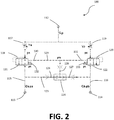
- a hoisting/auto-levelling hydraulic system implemented by a hydraulic circuit, is indicated by reference number 1.
- the system 1 can be for example applied to the machines discussed in the introductory part of the present description.
- the system 1 comprises a first supplying and unloading port/connection 2 and a second supplying and unloading port/connection 3.
- the supplying and unloading ports/connections 2, 3 are preferably connected or connectable to a storage reservoir and a pump, by a group of valves or a hydraulic distributor for example (not shown in the figures), for storing, for circulating and pressurizing a pressurized working fluid in the system 1, for example a pressurized oil, which is made reference to as an example in the following description.
- the system 1 comprises a first and second actuator groups.
- such first and second actuator groups comprise a hoisting cylinder-piston group 4 and an aligning cylinder-piston group 5, preferably of the double acting type.
- the first and second actuator groups can comprise any hydraulic and/or electronic actuating systems, for example a motor, a rotative actuator, a single acting cylinder, or similar.
- the hoisting cylinder-piston group 4 is particularly adapted to hoist and lower a mechanical arm, possibly an extendable one, supporting a tool of a machine (not shown in the figures), while the aligning cylinder-piston group 5 is connected or connectable to the above cited mechanical arm and tool so that this latter can be both inclined by commands provided by an operator (for example during a loading/unloading operation) and automatically commanded during an upward/downward operation of the arm by the hoisting cylinder-piston group 4 for being maintained with a predefined orientation from the ground, for example horizontal.
- the hoisting cylinder-piston group 4 comprises a first port/connection 6 for gaining access to the first chamber, for example on the bottom side of the same, and a second port/connection 7 for gaining access to a second chamber, for example on the stem side of the same.
- the above-cited two chambers are the two portions of the varying volume cylinder, separated by the piston of the cylinder-piston group. For example, when the oil flows through the first port/connection 6 in the first chamber, the piston performs a movement hoisting the tool and, consequently, the stored oil in the second chamber flows out through the second port/connection 7.
- the aligning cylinder-piston group 5 comprises a first port/connection 8 for gaining access to the first chamber and a second port/connection 9 for gaining access to the second chamber.
- the two above cited chambers are the two portions of the varying volume cylinder, separated by the piston of the cylinder-piston group. For example, when the oil flows through the first port/connection 8 of the first chamber, the piston performs a motion aligning the tool with a first direction and, consequently, the stored oil in the second chamber flows out through the second port/connection 9.
- System 1 comprises a first flow divider 10 and a second flow divider 11.
- the function of the flow dividers 10 and 11 is of separating an inlet flow in two outlet flows, ensuring the ratio of the two outlet flows is constant independently from the inlet supplying flow rate, and the outlet instantaneous flow rates remain constant independently from the hoisted load according to preset calibrations and adjustments.
- the first flow divider 10 comprises an inlet 12, a first outlet 13 and a second outlet 14. Moreover, the first flow divider 10 comprises a first branch 15 connecting the inlet 12 to the first outlet 13 and a second branch 16 connecting the inlet 12 to the second outlet 14.
- the first branch 14 comprises an element 17 for adjusting the through opening and a compensator 18 configured so that the fluid pressure between the adjusting element 17 and compensator 18 is constantly set equal to the pressure maximum value between the two outlets 13 and 14, up to a calibration constant (corresponding to a calibration value of an elastic element of the compensator itself, as it will be described).
- the second branch 16 comprises an element 19 for adjusting the through opening and a compensator 20 configured so that the fluid pressure between the adjusting element 19 and compensator 20 is constantly set equal to the pressure maximum value between the two outlets 13 and 14, up to a calibration constant (corresponding to the calibration value of an elastic element of the compensator itself, as it will be described in the following).
- the second flow divider 11 has a shape analogous to the one of the first flow divider 10.
- the second flow divider 11 comprises an inlet 21, a first outlet 22 and a second outlet 23.
- the second flow divider 11 comprises a first branch 24 connecting the inlet 21 to a first outlet 22 and a second branch 25 connecting the inlet 21 to the second outlet 23.
- the first branch 24 comprises an element 26 for adjusting the through passage and a compensator 27 configured so that the fluid pressure between the adjusting element 26 and compensator 27 is constantly held equal to the maximum pressure value between the outlets 22 and 23, up to a calibration constant (corresponding to a calibration value of an elastic element of the compensator itself, as it will be described in the following).
- the second branch 25 comprises an element 28 for adjusting the through opening and a compensator 29 configured so that the fluid pressure between the adjusting element 28 and compensator 29 is constantly held equal to a maximum pressure value between the two outlets 22 and 23, up to a calibration constant (corresponding to a calibration value of an elastic element of the compensator itself, as it will be described in the following).
- the system 1 is configured so that:
- system 1 is configured so that the flow dividers 10 and 11 are crossed only by the fluid flowing from the respective inlets to the respective outlets, and not the opposite.
- system 1 can be provided with a plurality of non-return valves, illustratively shown in Figure 1 .
- alternative arrangements of the circuit underlying the system 1 are also possible, which result in the same effect, as it will be evident to a person skilled in the art.
- the flow rate enters the first chamber of the hoisting cylinder-piston group 4 through the first port/connection 6.
- the flow rate exits the second chamber of the hoisting cylinder-piston group 4 through the second port/connection 7 and is divided by a preset percentage by the first flow divider 11, which distributes it between the second supplying and unloading port/connection 3 (in this case is connected to unload) and the first port/connection 8 which transfers the supply to the first chamber of the aligning cylinder/piston group 5, which will consequently maintain the same inclination of the tool from the ground.
- the flow rate supplies the second chamber of the hoisting cylinder-piston group 4 through the second port/connection 7.
- the flow divider 100 comprises an inlet 112, a first outlet 113 and a second outlet 114.
- the flow divider 10 comprises a first branch 115 connecting the inlet 112 to the first outlet 113 and a second branch 116 connecting the inlet 112 to the second outlet 114.
- the first branch 115 comprises an element 117 for adjusting the through opening and a compensator 118 configured so that the fluid pressure between the adjusting element 117 and compensator 118 is constantly held equal to the maximum pressure value between the two outlets 113 and 114, up to a calibration constant of a first calibration elastic element 132.
- the second branch 116 comprises an element 119 for adjusting the through opening and a compensator 120 configured so that the fluid pressure between the adjusting element 119 and compensator 120 is constantly held equal to the maximum pressure value between the two outlets 113 and 114, up to a calibration constant of a second calibration elastic element 133.
- the adjusting elements 117, 119 can comprise fixed or adjustable throttles, or proportional valves or similar, such to be capable of adjusting the through areas Ya and Yb respectively in the branches 115 and 116. Such adjustments can be performed by an operator, or automatically, as a function of the pressurized fluid flow rates which should be let flow in the first 115 and second branches 116.
- Hydraulic proportional valves mean internally and/or externally piloted/commanded valves capable of continuously varying their opening. These proportional valves are designed so that the pressure upstream them is equal to pc between the respective branches, (wherein pc is equal to the maximum pressure between the outlets 113 and 114, which is added to the pressure pk of the calibration elastic elements 132 and 133 of the compensators themselves), independently from the two pressures pa and pb downstream them in the two branches 115 and 116 (which, in turn, depend on the users connected at the outlet, for example on the load supported by the tool).
- the flow divider 100 comprises a connecting branch 123 downstream the first 121 and second proportional valves 122, hydraulically connecting the first branch 115 and second branch 116.
- This connecting branch 123 is provided with a three-way hydraulic valve 124 having a first inlet 126 connected to the first branch 115, a second inlet 127 connected to the second branch 116 and an outlet 128 hydraulically connected to a hydraulic pilot branch of the compensator 129 having a first end 130 so that the fluid inside it applies its pressure on the first proportional valve 121 and a second end 131 so that the fluid inside it applies its pressure on the second proportional valve 122.
- the three-way valve 124 is configured for keeping open the connection of the hydraulic pilot branch of the compensator 129 with the branch between the first 115 and second branches 116 of the divider 100 which is under the highest pressure condition.
- the three-way valve 124 is configured so that the pressure pis in the pilot branch of the compensators 129 is equal to the highest pressure between pa and pb.
- each proportional hydraulic valve 121 and 122 operate so that the pressure pc is equal to the sum of pressures pis and pk.
- the pressures in the two branches 115 and 116 upstream the proportional valves 121 and 122 are ensured to be always equal to pc. Consequently, the flow rates in the two branches Qa and Qb will depend only on the adjustments Ya and Yb of the adjusting elements 117 and 119, independently from the pressures pa and pb and from any supplying flow rate Q. In this way, the inlet flow rate Q can be accurately divided in two predefined outlet flow rates Qa and Qb.
- Inserting such dividers in the system 1, as illustrated in Figure 1 makes, given a determined flow rate from the hoisting cylinder-piston group 4, a predefined part of it to be supplied to the aligning cylinder-piston group 5, both in the upward step and downward step. Since the flow rates are related to the speeds of pistons, it is possible to define the respective speeds required to keep the alignment of the tool and consequently to adjust the flow dividers 10 and 11 so that they provide the correct flow rate to the aligning cylinder-piston group 5.
- the adjusting valves 117 and 119 can be electronically and/or hydraulically and/or mechanically adjusted.
- the functions of the proportional hydraulic valves 117 and 119 are incorporated in the adjusting elements 117 and compensator 118.
Landscapes
- Engineering & Computer Science (AREA)
- Mechanical Engineering (AREA)
- General Engineering & Computer Science (AREA)
- Fluid Mechanics (AREA)
- Physics & Mathematics (AREA)
- Transportation (AREA)
- Chemical & Material Sciences (AREA)
- Structural Engineering (AREA)
- Civil Engineering (AREA)
- Geology (AREA)
- Life Sciences & Earth Sciences (AREA)
- Combustion & Propulsion (AREA)
- Analytical Chemistry (AREA)
- Fluid-Pressure Circuits (AREA)
- Load-Engaging Elements For Cranes (AREA)
- Forklifts And Lifting Vehicles (AREA)
Applications Claiming Priority (1)
| Application Number | Priority Date | Filing Date | Title |
|---|---|---|---|
| IT102019000007047A IT201900007047A1 (it) | 2019-05-21 | 2019-05-21 | Sistema idraulico di sollevamento e auto-livellamento di un attrezzo |
Publications (2)
| Publication Number | Publication Date |
|---|---|
| EP3742001A1 true EP3742001A1 (de) | 2020-11-25 |
| EP3742001B1 EP3742001B1 (de) | 2023-01-25 |
Family
ID=67957274
Family Applications (1)
| Application Number | Title | Priority Date | Filing Date |
|---|---|---|---|
| EP20165275.7A Active EP3742001B1 (de) | 2019-05-21 | 2020-03-24 | Hydrauliksystem zum anheben und automatischen nivellieren eines werkzeugs |
Country Status (2)
| Country | Link |
|---|---|
| EP (1) | EP3742001B1 (de) |
| IT (1) | IT201900007047A1 (de) |
Citations (3)
| Publication number | Priority date | Publication date | Assignee | Title |
|---|---|---|---|---|
| US4815357A (en) * | 1987-07-21 | 1989-03-28 | Lull Corp. | Adjustable divided flow self-leveling system |
| US6308612B1 (en) * | 1998-09-24 | 2001-10-30 | Delta Power Company | Hydraulic leveling control system for a loader type vehicle |
| EP3495565A1 (de) * | 2017-12-05 | 2019-06-12 | Dalmasso, Giacomo | Ventileinheit, insbesondere zur steuerung eines gelenkarms mit einem werkzeug |
-
2019
- 2019-05-21 IT IT102019000007047A patent/IT201900007047A1/it unknown
-
2020
- 2020-03-24 EP EP20165275.7A patent/EP3742001B1/de active Active
Patent Citations (3)
| Publication number | Priority date | Publication date | Assignee | Title |
|---|---|---|---|---|
| US4815357A (en) * | 1987-07-21 | 1989-03-28 | Lull Corp. | Adjustable divided flow self-leveling system |
| US6308612B1 (en) * | 1998-09-24 | 2001-10-30 | Delta Power Company | Hydraulic leveling control system for a loader type vehicle |
| EP3495565A1 (de) * | 2017-12-05 | 2019-06-12 | Dalmasso, Giacomo | Ventileinheit, insbesondere zur steuerung eines gelenkarms mit einem werkzeug |
Also Published As
| Publication number | Publication date |
|---|---|
| EP3742001B1 (de) | 2023-01-25 |
| IT201900007047A1 (it) | 2020-11-21 |
Similar Documents
| Publication | Publication Date | Title |
|---|---|---|
| US20240425104A1 (en) | System architectures for steering and work functions in a wheel loader | |
| US9206821B2 (en) | Hydraulic switching mechanism for mobile hydraulics, mobile hydraulic machine and valve unit | |
| US8671824B2 (en) | Hydraulic control system | |
| US8522543B2 (en) | Hydraulic control system utilizing feed-forward control | |
| US9394666B2 (en) | Construction machine with working attachment | |
| US20130167518A1 (en) | Control Arrangement and Method for Activating a Plurality of Hydrualic Consumers | |
| AU2007249080B2 (en) | Hydraulic valve arrangement | |
| US20030121256A1 (en) | Pressure-compensating valve with load check | |
| JP7065582B2 (ja) | 液圧システム及び液圧システムを含む建設機械 | |
| US11268545B2 (en) | Hydraulic control arrangement for supplying pressure medium to at least two hydraulic consumers | |
| US9797419B2 (en) | Hydraulic system with energy recovery | |
| US11186967B2 (en) | Hydraulic systems for construction machinery | |
| US7614336B2 (en) | Hydraulic system having augmented pressure compensation | |
| US20130280097A1 (en) | Hydraulic system | |
| KR102535297B1 (ko) | 유체 회로 | |
| US7320216B2 (en) | Hydraulic system having pressure compensated bypass | |
| US4129987A (en) | Hydraulic control system | |
| US10889964B2 (en) | Drive system for construction machine | |
| US20100212308A1 (en) | Hydraulic control arrangement | |
| US9404483B2 (en) | Hydraulic control arrangement | |
| EP3742001B1 (de) | Hydrauliksystem zum anheben und automatischen nivellieren eines werkzeugs | |
| US7614335B2 (en) | Hydraulic system with variable standby pressure | |
| KR101977112B1 (ko) | 건설 기계의 폐회로 유압 시스템 |
Legal Events
| Date | Code | Title | Description |
|---|---|---|---|
| PUAI | Public reference made under article 153(3) epc to a published international application that has entered the european phase |
Free format text: ORIGINAL CODE: 0009012 |
|
| STAA | Information on the status of an ep patent application or granted ep patent |
Free format text: STATUS: THE APPLICATION HAS BEEN PUBLISHED |
|
| AK | Designated contracting states |
Kind code of ref document: A1 Designated state(s): AL AT BE BG CH CY CZ DE DK EE ES FI FR GB GR HR HU IE IS IT LI LT LU LV MC MK MT NL NO PL PT RO RS SE SI SK SM TR |
|
| AX | Request for extension of the european patent |
Extension state: BA ME |
|
| STAA | Information on the status of an ep patent application or granted ep patent |
Free format text: STATUS: REQUEST FOR EXAMINATION WAS MADE |
|
| 17P | Request for examination filed |
Effective date: 20210219 |
|
| RBV | Designated contracting states (corrected) |
Designated state(s): AL AT BE BG CH CY CZ DE DK EE ES FI FR GB GR HR HU IE IS IT LI LT LU LV MC MK MT NL NO PL PT RO RS SE SI SK SM TR |
|
| STAA | Information on the status of an ep patent application or granted ep patent |
Free format text: STATUS: EXAMINATION IS IN PROGRESS |
|
| 17Q | First examination report despatched |
Effective date: 20220204 |
|
| GRAP | Despatch of communication of intention to grant a patent |
Free format text: ORIGINAL CODE: EPIDOSNIGR1 |
|
| STAA | Information on the status of an ep patent application or granted ep patent |
Free format text: STATUS: GRANT OF PATENT IS INTENDED |
|
| INTG | Intention to grant announced |
Effective date: 20221018 |
|
| GRAS | Grant fee paid |
Free format text: ORIGINAL CODE: EPIDOSNIGR3 |
|
| GRAA | (expected) grant |
Free format text: ORIGINAL CODE: 0009210 |
|
| STAA | Information on the status of an ep patent application or granted ep patent |
Free format text: STATUS: THE PATENT HAS BEEN GRANTED |
|
| AK | Designated contracting states |
Kind code of ref document: B1 Designated state(s): AL AT BE BG CH CY CZ DE DK EE ES FI FR GB GR HR HU IE IS IT LI LT LU LV MC MK MT NL NO PL PT RO RS SE SI SK SM TR |
|
| REG | Reference to a national code |
Ref country code: GB Ref legal event code: FG4D |
|
| REG | Reference to a national code |
Ref country code: CH Ref legal event code: EP |
|
| REG | Reference to a national code |
Ref country code: AT Ref legal event code: REF Ref document number: 1546094 Country of ref document: AT Kind code of ref document: T Effective date: 20230215 Ref country code: IE Ref legal event code: FG4D |
|
| REG | Reference to a national code |
Ref country code: DE Ref legal event code: R096 Ref document number: 602020007752 Country of ref document: DE |
|
| REG | Reference to a national code |
Ref country code: LT Ref legal event code: MG9D |
|
| REG | Reference to a national code |
Ref country code: NL Ref legal event code: MP Effective date: 20230125 |
|
| REG | Reference to a national code |
Ref country code: AT Ref legal event code: MK05 Ref document number: 1546094 Country of ref document: AT Kind code of ref document: T Effective date: 20230125 |
|
| PG25 | Lapsed in a contracting state [announced via postgrant information from national office to epo] |
Ref country code: NL Free format text: LAPSE BECAUSE OF FAILURE TO SUBMIT A TRANSLATION OF THE DESCRIPTION OR TO PAY THE FEE WITHIN THE PRESCRIBED TIME-LIMIT Effective date: 20230125 |
|
| PG25 | Lapsed in a contracting state [announced via postgrant information from national office to epo] |
Ref country code: RS Free format text: LAPSE BECAUSE OF FAILURE TO SUBMIT A TRANSLATION OF THE DESCRIPTION OR TO PAY THE FEE WITHIN THE PRESCRIBED TIME-LIMIT Effective date: 20230125 Ref country code: PT Free format text: LAPSE BECAUSE OF FAILURE TO SUBMIT A TRANSLATION OF THE DESCRIPTION OR TO PAY THE FEE WITHIN THE PRESCRIBED TIME-LIMIT Effective date: 20230525 Ref country code: NO Free format text: LAPSE BECAUSE OF FAILURE TO SUBMIT A TRANSLATION OF THE DESCRIPTION OR TO PAY THE FEE WITHIN THE PRESCRIBED TIME-LIMIT Effective date: 20230425 Ref country code: LV Free format text: LAPSE BECAUSE OF FAILURE TO SUBMIT A TRANSLATION OF THE DESCRIPTION OR TO PAY THE FEE WITHIN THE PRESCRIBED TIME-LIMIT Effective date: 20230125 Ref country code: LT Free format text: LAPSE BECAUSE OF FAILURE TO SUBMIT A TRANSLATION OF THE DESCRIPTION OR TO PAY THE FEE WITHIN THE PRESCRIBED TIME-LIMIT Effective date: 20230125 Ref country code: HR Free format text: LAPSE BECAUSE OF FAILURE TO SUBMIT A TRANSLATION OF THE DESCRIPTION OR TO PAY THE FEE WITHIN THE PRESCRIBED TIME-LIMIT Effective date: 20230125 Ref country code: ES Free format text: LAPSE BECAUSE OF FAILURE TO SUBMIT A TRANSLATION OF THE DESCRIPTION OR TO PAY THE FEE WITHIN THE PRESCRIBED TIME-LIMIT Effective date: 20230125 Ref country code: AT Free format text: LAPSE BECAUSE OF FAILURE TO SUBMIT A TRANSLATION OF THE DESCRIPTION OR TO PAY THE FEE WITHIN THE PRESCRIBED TIME-LIMIT Effective date: 20230125 |
|
| PG25 | Lapsed in a contracting state [announced via postgrant information from national office to epo] |
Ref country code: SE Free format text: LAPSE BECAUSE OF FAILURE TO SUBMIT A TRANSLATION OF THE DESCRIPTION OR TO PAY THE FEE WITHIN THE PRESCRIBED TIME-LIMIT Effective date: 20230125 Ref country code: PL Free format text: LAPSE BECAUSE OF FAILURE TO SUBMIT A TRANSLATION OF THE DESCRIPTION OR TO PAY THE FEE WITHIN THE PRESCRIBED TIME-LIMIT Effective date: 20230125 Ref country code: IS Free format text: LAPSE BECAUSE OF FAILURE TO SUBMIT A TRANSLATION OF THE DESCRIPTION OR TO PAY THE FEE WITHIN THE PRESCRIBED TIME-LIMIT Effective date: 20230525 Ref country code: GR Free format text: LAPSE BECAUSE OF FAILURE TO SUBMIT A TRANSLATION OF THE DESCRIPTION OR TO PAY THE FEE WITHIN THE PRESCRIBED TIME-LIMIT Effective date: 20230426 Ref country code: FI Free format text: LAPSE BECAUSE OF FAILURE TO SUBMIT A TRANSLATION OF THE DESCRIPTION OR TO PAY THE FEE WITHIN THE PRESCRIBED TIME-LIMIT Effective date: 20230125 |
|
| REG | Reference to a national code |
Ref country code: DE Ref legal event code: R097 Ref document number: 602020007752 Country of ref document: DE |
|
| PG25 | Lapsed in a contracting state [announced via postgrant information from national office to epo] |
Ref country code: SM Free format text: LAPSE BECAUSE OF FAILURE TO SUBMIT A TRANSLATION OF THE DESCRIPTION OR TO PAY THE FEE WITHIN THE PRESCRIBED TIME-LIMIT Effective date: 20230125 Ref country code: RO Free format text: LAPSE BECAUSE OF FAILURE TO SUBMIT A TRANSLATION OF THE DESCRIPTION OR TO PAY THE FEE WITHIN THE PRESCRIBED TIME-LIMIT Effective date: 20230125 Ref country code: MC Free format text: LAPSE BECAUSE OF FAILURE TO SUBMIT A TRANSLATION OF THE DESCRIPTION OR TO PAY THE FEE WITHIN THE PRESCRIBED TIME-LIMIT Effective date: 20230125 Ref country code: EE Free format text: LAPSE BECAUSE OF FAILURE TO SUBMIT A TRANSLATION OF THE DESCRIPTION OR TO PAY THE FEE WITHIN THE PRESCRIBED TIME-LIMIT Effective date: 20230125 Ref country code: DK Free format text: LAPSE BECAUSE OF FAILURE TO SUBMIT A TRANSLATION OF THE DESCRIPTION OR TO PAY THE FEE WITHIN THE PRESCRIBED TIME-LIMIT Effective date: 20230125 Ref country code: CZ Free format text: LAPSE BECAUSE OF FAILURE TO SUBMIT A TRANSLATION OF THE DESCRIPTION OR TO PAY THE FEE WITHIN THE PRESCRIBED TIME-LIMIT Effective date: 20230125 |
|
| REG | Reference to a national code |
Ref country code: CH Ref legal event code: PL |
|
| PG25 | Lapsed in a contracting state [announced via postgrant information from national office to epo] |
Ref country code: SK Free format text: LAPSE BECAUSE OF FAILURE TO SUBMIT A TRANSLATION OF THE DESCRIPTION OR TO PAY THE FEE WITHIN THE PRESCRIBED TIME-LIMIT Effective date: 20230125 |
|
| REG | Reference to a national code |
Ref country code: BE Ref legal event code: MM Effective date: 20230331 |
|
| PLBE | No opposition filed within time limit |
Free format text: ORIGINAL CODE: 0009261 |
|
| STAA | Information on the status of an ep patent application or granted ep patent |
Free format text: STATUS: NO OPPOSITION FILED WITHIN TIME LIMIT |
|
| PG25 | Lapsed in a contracting state [announced via postgrant information from national office to epo] |
Ref country code: LU Free format text: LAPSE BECAUSE OF NON-PAYMENT OF DUE FEES Effective date: 20230324 |
|
| 26N | No opposition filed |
Effective date: 20231026 |
|
| REG | Reference to a national code |
Ref country code: IE Ref legal event code: MM4A |
|
| PG25 | Lapsed in a contracting state [announced via postgrant information from national office to epo] |
Ref country code: SI Free format text: LAPSE BECAUSE OF FAILURE TO SUBMIT A TRANSLATION OF THE DESCRIPTION OR TO PAY THE FEE WITHIN THE PRESCRIBED TIME-LIMIT Effective date: 20230125 Ref country code: LI Free format text: LAPSE BECAUSE OF NON-PAYMENT OF DUE FEES Effective date: 20230331 Ref country code: IE Free format text: LAPSE BECAUSE OF NON-PAYMENT OF DUE FEES Effective date: 20230324 Ref country code: CH Free format text: LAPSE BECAUSE OF NON-PAYMENT OF DUE FEES Effective date: 20230331 |
|
| PG25 | Lapsed in a contracting state [announced via postgrant information from national office to epo] |
Ref country code: BE Free format text: LAPSE BECAUSE OF NON-PAYMENT OF DUE FEES Effective date: 20230331 |
|
| PG25 | Lapsed in a contracting state [announced via postgrant information from national office to epo] |
Ref country code: IT Free format text: LAPSE BECAUSE OF FAILURE TO SUBMIT A TRANSLATION OF THE DESCRIPTION OR TO PAY THE FEE WITHIN THE PRESCRIBED TIME-LIMIT Effective date: 20230125 |
|
| PG25 | Lapsed in a contracting state [announced via postgrant information from national office to epo] |
Ref country code: BG Free format text: LAPSE BECAUSE OF FAILURE TO SUBMIT A TRANSLATION OF THE DESCRIPTION OR TO PAY THE FEE WITHIN THE PRESCRIBED TIME-LIMIT Effective date: 20230125 |
|
| PG25 | Lapsed in a contracting state [announced via postgrant information from national office to epo] |
Ref country code: BG Free format text: LAPSE BECAUSE OF FAILURE TO SUBMIT A TRANSLATION OF THE DESCRIPTION OR TO PAY THE FEE WITHIN THE PRESCRIBED TIME-LIMIT Effective date: 20230125 |
|
| PGFP | Annual fee paid to national office [announced via postgrant information from national office to epo] |
Ref country code: DE Payment date: 20250319 Year of fee payment: 6 |
|
| PGFP | Annual fee paid to national office [announced via postgrant information from national office to epo] |
Ref country code: FR Payment date: 20250324 Year of fee payment: 6 |
|
| PGFP | Annual fee paid to national office [announced via postgrant information from national office to epo] |
Ref country code: GB Payment date: 20250303 Year of fee payment: 6 |
|
| PG25 | Lapsed in a contracting state [announced via postgrant information from national office to epo] |
Ref country code: CY Free format text: LAPSE BECAUSE OF FAILURE TO SUBMIT A TRANSLATION OF THE DESCRIPTION OR TO PAY THE FEE WITHIN THE PRESCRIBED TIME-LIMIT; INVALID AB INITIO Effective date: 20200324 |
|
| PG25 | Lapsed in a contracting state [announced via postgrant information from national office to epo] |
Ref country code: HU Free format text: LAPSE BECAUSE OF FAILURE TO SUBMIT A TRANSLATION OF THE DESCRIPTION OR TO PAY THE FEE WITHIN THE PRESCRIBED TIME-LIMIT; INVALID AB INITIO Effective date: 20200324 |
|
| PG25 | Lapsed in a contracting state [announced via postgrant information from national office to epo] |
Ref country code: TR Free format text: LAPSE BECAUSE OF FAILURE TO SUBMIT A TRANSLATION OF THE DESCRIPTION OR TO PAY THE FEE WITHIN THE PRESCRIBED TIME-LIMIT Effective date: 20230125 |