EP3741995B1 - Spiralfluidmaschine - Google Patents
Spiralfluidmaschine Download PDFInfo
- Publication number
- EP3741995B1 EP3741995B1 EP19757122.7A EP19757122A EP3741995B1 EP 3741995 B1 EP3741995 B1 EP 3741995B1 EP 19757122 A EP19757122 A EP 19757122A EP 3741995 B1 EP3741995 B1 EP 3741995B1
- Authority
- EP
- European Patent Office
- Prior art keywords
- wall
- end plate
- section
- scroll
- tooth
- Prior art date
- Legal status (The legal status is an assumption and is not a legal conclusion. Google has not performed a legal analysis and makes no representation as to the accuracy of the status listed.)
- Active
Links
Images


Classifications
-
- F—MECHANICAL ENGINEERING; LIGHTING; HEATING; WEAPONS; BLASTING
- F04—POSITIVE - DISPLACEMENT MACHINES FOR LIQUIDS; PUMPS FOR LIQUIDS OR ELASTIC FLUIDS
- F04C—ROTARY-PISTON, OR OSCILLATING-PISTON, POSITIVE-DISPLACEMENT MACHINES FOR LIQUIDS; ROTARY-PISTON, OR OSCILLATING-PISTON, POSITIVE-DISPLACEMENT PUMPS
- F04C18/00—Rotary-piston pumps specially adapted for elastic fluids
- F04C18/02—Rotary-piston pumps specially adapted for elastic fluids of arcuate-engagement type, i.e. with circular translatory movement of co-operating members, each member having the same number of teeth or tooth-equivalents
- F04C18/0207—Rotary-piston pumps specially adapted for elastic fluids of arcuate-engagement type, i.e. with circular translatory movement of co-operating members, each member having the same number of teeth or tooth-equivalents both members having co-operating elements in spiral form
- F04C18/0246—Details concerning the involute wraps or their base, e.g. geometry
- F04C18/0269—Details concerning the involute wraps
- F04C18/0276—Different wall heights
-
- F—MECHANICAL ENGINEERING; LIGHTING; HEATING; WEAPONS; BLASTING
- F01—MACHINES OR ENGINES IN GENERAL; ENGINE PLANTS IN GENERAL; STEAM ENGINES
- F01C—ROTARY-PISTON OR OSCILLATING-PISTON MACHINES OR ENGINES
- F01C1/00—Rotary-piston machines or engines
- F01C1/02—Rotary-piston machines or engines of arcuate-engagement type, i.e. with circular translatory movement of co-operating members, each member having the same number of teeth or tooth-equivalents
- F01C1/0207—Rotary-piston machines or engines of arcuate-engagement type, i.e. with circular translatory movement of co-operating members, each member having the same number of teeth or tooth-equivalents both members having co-operating elements in spiral form
- F01C1/0215—Rotary-piston machines or engines of arcuate-engagement type, i.e. with circular translatory movement of co-operating members, each member having the same number of teeth or tooth-equivalents both members having co-operating elements in spiral form where only one member is moving
-
- F—MECHANICAL ENGINEERING; LIGHTING; HEATING; WEAPONS; BLASTING
- F01—MACHINES OR ENGINES IN GENERAL; ENGINE PLANTS IN GENERAL; STEAM ENGINES
- F01C—ROTARY-PISTON OR OSCILLATING-PISTON MACHINES OR ENGINES
- F01C21/00—Component parts, details or accessories not provided for in groups F01C1/00 - F01C20/00
- F01C21/08—Rotary pistons
-
- F—MECHANICAL ENGINEERING; LIGHTING; HEATING; WEAPONS; BLASTING
- F01—MACHINES OR ENGINES IN GENERAL; ENGINE PLANTS IN GENERAL; STEAM ENGINES
- F01C—ROTARY-PISTON OR OSCILLATING-PISTON MACHINES OR ENGINES
- F01C21/00—Component parts, details or accessories not provided for in groups F01C1/00 - F01C20/00
- F01C21/10—Outer members for co-operation with rotary pistons; Casings
-
- F—MECHANICAL ENGINEERING; LIGHTING; HEATING; WEAPONS; BLASTING
- F04—POSITIVE - DISPLACEMENT MACHINES FOR LIQUIDS; PUMPS FOR LIQUIDS OR ELASTIC FLUIDS
- F04C—ROTARY-PISTON, OR OSCILLATING-PISTON, POSITIVE-DISPLACEMENT MACHINES FOR LIQUIDS; ROTARY-PISTON, OR OSCILLATING-PISTON, POSITIVE-DISPLACEMENT PUMPS
- F04C18/00—Rotary-piston pumps specially adapted for elastic fluids
- F04C18/02—Rotary-piston pumps specially adapted for elastic fluids of arcuate-engagement type, i.e. with circular translatory movement of co-operating members, each member having the same number of teeth or tooth-equivalents
- F04C18/0207—Rotary-piston pumps specially adapted for elastic fluids of arcuate-engagement type, i.e. with circular translatory movement of co-operating members, each member having the same number of teeth or tooth-equivalents both members having co-operating elements in spiral form
- F04C18/0215—Rotary-piston pumps specially adapted for elastic fluids of arcuate-engagement type, i.e. with circular translatory movement of co-operating members, each member having the same number of teeth or tooth-equivalents both members having co-operating elements in spiral form where only one member is moving
-
- F—MECHANICAL ENGINEERING; LIGHTING; HEATING; WEAPONS; BLASTING
- F04—POSITIVE - DISPLACEMENT MACHINES FOR LIQUIDS; PUMPS FOR LIQUIDS OR ELASTIC FLUIDS
- F04C—ROTARY-PISTON, OR OSCILLATING-PISTON, POSITIVE-DISPLACEMENT MACHINES FOR LIQUIDS; ROTARY-PISTON, OR OSCILLATING-PISTON, POSITIVE-DISPLACEMENT PUMPS
- F04C18/00—Rotary-piston pumps specially adapted for elastic fluids
- F04C18/02—Rotary-piston pumps specially adapted for elastic fluids of arcuate-engagement type, i.e. with circular translatory movement of co-operating members, each member having the same number of teeth or tooth-equivalents
- F04C18/0207—Rotary-piston pumps specially adapted for elastic fluids of arcuate-engagement type, i.e. with circular translatory movement of co-operating members, each member having the same number of teeth or tooth-equivalents both members having co-operating elements in spiral form
- F04C18/0246—Details concerning the involute wraps or their base, e.g. geometry
- F04C18/0253—Details concerning the base
-
- F—MECHANICAL ENGINEERING; LIGHTING; HEATING; WEAPONS; BLASTING
- F04—POSITIVE - DISPLACEMENT MACHINES FOR LIQUIDS; PUMPS FOR LIQUIDS OR ELASTIC FLUIDS
- F04C—ROTARY-PISTON, OR OSCILLATING-PISTON, POSITIVE-DISPLACEMENT MACHINES FOR LIQUIDS; ROTARY-PISTON, OR OSCILLATING-PISTON, POSITIVE-DISPLACEMENT PUMPS
- F04C2240/00—Components
- F04C2240/20—Rotors
Definitions
- a so-called stepped scroll compressor disclosed in PTL 1 is known.
- respective step sections are provided at positions along the spiral directions of tooth tip surfaces and tooth bottom surfaces of spiral walls of a fixed scroll and a turning scroll, and the height of the outer circumferential side of the wall is made higher than the height of the inner circumferential side of the wall with each step section as a boundary.
- the stepped scroll compressor performs compression not only in the circumferential direction of the walls, but also in the height direction (three-dimensional compression), and therefore it is possible to increase displacement and increase compressor capacity compared to a general scroll compressor with no step section (two-dimensional compression).
- PTL 2 discloses a scroll fluid machine including a wall body and an end plate that are capable of reducing a tip clearance between a tooth tip of the wall body and a tooth bottom of the end plate.
- PTL 3 discloses a scroll compressor in which a bottom surface is provided with a stratum with several height differences, so that an axial volume-variation is provided in operation.
- the stepped scroll compressor has a problem that fluid leakage at the step sections is large. Further, there is a problem that stress is concentrated on root portions of the step sections, and strength is reduced.
- the inventors are considering providing continuous inclined sections in place of the step sections provided on the walls and the end plates.
- the present invention has been made in view of such a circumstance, and an object of the present invention is to provide a scroll fluid machine having inclined sections in a wall and an end plate capable of reducing a tip clearance between a tooth tip of the wall and a tooth bottom of the end plate.
- a scroll fluid machine of the present invention employs the following solutions.
- a scroll fluid machine is a scroll fluid machine including: a first scroll member provided with a spiral first wall on a first end plate; and a second scroll member that is provided with a spiral second wall on a second end plate disposed so as to face the first end plate, and that relatively revolves by engagement between the second wall and the first wall with the second wall being offset from the first wall by a turning radius, wherein an inclined section that continuously reduces an inter-facing-surface distance between the first end plate and the second end plate facing each other, from an outer circumferential side toward an inner circumferential side of each of the first wall and the second wall is provided, each of the inclined sections is provided over a range of 180° or more around a spiral center, at least one of the first wall and the second wall has a wall inclined section that has a height of the wall continuously reducing from the outer circumferential side toward the inner circumferential side so as to form the inclined section, at least one of the first end plate and the second end plate has an end plate inclined section having
- the inclined section that continuously reduces the inter-facing-surface distance between the first end plate and the second end plate from the outer circumferential side toward the inner circumferential side of each wall is provided, and therefore fluid sucked from the outer circumferential side is not only compressed by reduction of volume of compression chambers in accordance with the spiral shape of the wall, but also further compressed by reduction of the inter-facing-surface distance between the end plates, toward the inner circumferential side.
- At least one of the first end plate and the second end plate has the end plate inclined section having the tooth bottom surface that faces the tooth tip of the wall inclined section, and that inclines in accordance with the inclination of the wall inclined section, a wall flat section having no change in height is provided in an outermost circumferential part and/or an innermost circumferential part of each of the first wall and the second wall, an end plate flat section corresponding to the wall flat section is provided in each of the first end plate and the second end plate, and a wall inclined connecting section that connects the wall inclined section and the wall flat section is disposed with a phase delayed by the turning radius with respect to an end plate inclined connecting section that connects the end plate inclined section and the end plate flat section.
- the contour line is formed in the direction orthogonal to the spiral direction of the wall, on the end plate inclined section, that is, the tooth bottom.
- the tooth bottom and the tooth tip may interfere with each other at the time of turning movement of both the scroll members.
- the wall inclined connecting section is disposed with the phase delayed by the turning radius with respect to the end plate inclined connecting section. Consequently, it is possible to avoid interference between the tooth bottom and the tooth tip.
- the end plate inclined connecting section and the wall inclined connecting section engage with each other such that the positions thereof coincide with each other, and therefore it is possible to reduce a tip clearance between the tooth tip and the tooth bottom.
- the inclined section that continuously reduces the inter-facing-surface distance between the first end plate and the second end plate from the outer circumferential side toward the inner circumferential side of each wall is provided, and therefore fluid sucked from the outer circumferential side is not only compressed by reduction of volume of compression chambers in accordance with the spiral shape of the wall, but also further compressed by reduction of the inter-facing-surface distance between the end plates, toward the inner circumferential side.
- the one or the plurality of circular arcs each having the intersection with the wall as the contact point is formed as the contour line on the end plate inclined section.
- the tooth tip and the tooth bottom do not interfere with each other at the time of the turning movement, and it is possible to reduce a tip clearance between the tooth tip and the tooth bottom.
- the one or the plurality of circular arcs each having the intersection of the wall and the end plate inclined connecting section that connects the end plate inclined section and the end plate flat section as the contact point is formed as the contour line on the end plate inclined section.
- the wall inclined connecting section is disposed so as to coincide with the end plate inclined connecting section at the turning center position in the spiral direction at the time of the turning movement, that is, the end plate inclined connecting section and the wall inclined connecting section are disposed so as to have the same phase, the tooth tip and the tooth bottom do not interfere with each other at the time of the turning movement, and it is possible to reduce a tip clearance between the tooth tip and the tooth bottom.
- machining is preferably performed by use of an end mill having a diameter equal to or smaller than a tooth bottom width of the end plate inclined section.
- a diameter of the circular arc forming the contour line is denoted by De
- a tooth bottom width of the end plate inclined section is denoted by Tg
- the turning radius in the turning movement is denoted by ⁇
- De Tg 2 + 2 ⁇ 2 / 2 Tg is satisfied.
- De Tg2 + 2 ⁇ 2 / 2 Tg is satisfied, so that when the tooth tip and the tooth bottom come closest to each other at the time of turning movement, a tip clearance between the contour line and the wall inclined connecting section can approach zero.
- the wall inclined connecting section is disposed with the phase delayed by the turning radius with respect to the end plate inclined connecting section. Consequently, the tooth tip and the tooth bottom do not interfere with each other at the time of the turning movement, and it is possible to reduce a tip clearance between the tooth tip and the tooth bottom.
- the wall inclined connecting section is disposed so as to coincide with the end plate inclined connecting section at the turning center position in the spiral direction at the time of turning movement. Consequently, the tooth tip and the tooth bottom do not interfere with each other at the time of the turning movement, and it is possible to reduce a tip clearance between the tooth tip and the tooth bottom.
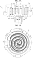
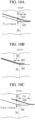
- Fig. 1 illustrates a fixed scroll (first scroll member) 3 and a turning scroll (second scroll member) 5 of a scroll compressor (scroll fluid machine) 1.
- the scroll compressor 1 is used as a compressor that compresses a gas refrigerant (fluid) for performing refrigerating cycle of an air conditioner or the like, for example.
- the fixed scroll 3 and the turning scroll 5 are a compression mechanism made of metal such as aluminum alloy and iron, and are housed in a housing (not illustrated).
- the fixed scroll 3 and the turning scroll 5 suck, from the outer circumferential side, fluid guided into the housing, and discharge the compressed fluid from a discharge port 3c at the center of the fixed scroll 3 to the outside.
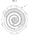
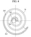
- the fixed scroll 3 is fixed to the housing, and includes a substantially disk-shaped end plate (first end plate) 3a, and a spiral wall (first wall) 3b erected on a side surface of the end plate 3a, as illustrated in Fig. 1A .
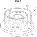
- the turning scroll 5 includes a substantially disk-shaped end plate (second end plate) 5a, and a spiral wall (second wall) 5b erected on a side surface of the end plate 5a.
- the respective spiral shapes of the walls 3b, 5b are each defined by using, for example, an involute curve or an Archimedes curve.
- the center of the fixed scroll 3 and the center of the turning scroll 5 are separated by a turning radius ⁇ , are engaged such that the phases of the walls 3b, 5b are shifted by 180°, and are assembled so as to have slight clearances (tip clearances) in the height direction between tooth tips and tooth bottoms of the walls 3b, 5b of both the scrolls at normal temperature. Consequently, a plurality of pairs of compression chambers formed so as to be surrounded by the end plates 3a, 5a and the walls 3b, 5b are formed between the scrolls 3, 5 so as to be symmetrical with respect to the scroll centers.
- the turning scroll 5 revolves around the fixed scroll 3 by a rotation prevention mechanism such as an Oldham ring (not illustrated).
- a wall inclined section 5b1 having a height that continuously reduces from the outer circumferential side toward inner circumferential side is provided in the wall 5b of the turning scroll 5.
- An end plate inclined section 3a1 (see Fig. 1A ) that inclines in accordance with inclination of the wall inclined section 5b1 is provided in a tooth bottom surface of the fixed scroll 3 facing a tooth tip of this wall inclined section 5b1.
- the continuous inclined section is formed by these wall inclined section 5b1 and end plate inclined section 3a1.
- a wall inclined section 3b1 having a height that continuously inclines from the outer circumferential side toward inner circumferential side is provided in the wall 3b of the fixed scroll 3, and an end plate inclined section 5a1 facing a tooth tip of this wall inclined section 3b1 is provided in the end plate 5a of the turning scroll 5.
- the meaning of "continuously” in the inclined section mentioned in this embodiment is not limited to smoothly connected inclination, but includes inclination that is formed by stepwisely connecting small steps inevitably generated in machining, and that is an inclined section continuously inclined as a whole. However, the above meaning does not include a large step such as a so-called stepped scroll.
- the wall inclined sections 3b1, 5b1 and/or the end plate inclined sections 3a1, 5a1 are coated.
- the coating include manganese phosphate treatment, and nickel-phosphorus plating.
- wall flat sections 5b2, 5b3 each having a constant height are provided on the innermost circumferential side and the outermost circumferential side of the wall 5b of the turning scroll 5, respectively.
- These wall flat sections 5b2, 5b3 are each provided over a region of 180° around the center 02 (see Fig. 1A ) of the turning scroll 5.
- Wall inclined connecting sections 5b4, 5b5 serving as bent sections are provided at respective positions where the wall flat sections 5b2, 5b3 and the wall inclined section 5b1 are connected.
- end plate flat sections 5a2, 5a3 each having a constant height are provided on a tooth bottom of the end plate 5a of the turning scroll 5.
- These end plate flat sections 5a2, 5a3 are also each provided over a region of 180° around the center of the turning scroll 5.
- End plate inclined connecting sections 5a4, 5a5 serving as bent sections are provided at respective positions where the end plate flat sections 5a2, 5a3 and the end plate inclined section 5a1 are connected.
- end plate flat sections 3a2, 3a3, wall flat sections 3b2, 3b3, end plate inclined connecting sections 3a4, 3a5, and wall inclined connecting sections 3b4, 3b5 are provided in the fixed scroll 3, like the turning scroll 5.
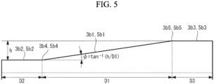
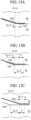
- Fig. 5 illustrates the walls 3b, 5b represented so as to extend in the spiral direction.
- the wall flat sections 3b2, 5b2 on the innermost circumferential sides are each provided so as to extend over a distance D2
- the wall flat sections 3b3, 5b3 on the outermost circumferential sides are each provided so as to extend over a distance D3.
- the distance D2 and the distance D3 are equivalent to the lengths of the regions of 180° (180° or more and 360° or less, preferably 210° or less) around the centers O1, O2 of the scrolls 3, 5.
- the wall inclined sections 3b1, 5b1 are provided between the wall flat sections 3b2, 5b2 on the innermost circumferential sides and the wall flat sections 3b3, 5b3 on the outermost circumferential sides so as to extend over a distance D1.
- the specifications of the scrolls 3, 5 are as follows.
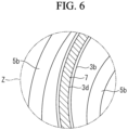
- a tip seal 7 is provided on the tooth tip of the wall 3b of the fixed scroll 3.
- the tip seal 7 is made of resin, and comes into contact with the tooth bottom of the end plate 5a of the facing turning scroll 5 to seal fluid.
- the tip seal 7 is housed in a tip seal groove 3d formed in the circumferential direction of the tooth tip of the wall 3b. Compressed fluid enters this tip seal groove 3d, and the tip seal 7 is pressed from a back surface, and pressed out to the tooth bottom side to be brought into contact with the facing tooth bottom.
- a tip seal is provided on the tooth tip of the wall 5b of the turning scroll 5.
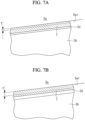
- a tip clearance change amount ⁇ h [mm] is, for example, 0.05 or more and 1.0 or less, preferably 0.1 or more and 0.6 or less.
- the tip clearance T is small in Fig. 7A
- the tip clearance T is large in Fig. 7B . Even when this tip clearance T changes due to the turning movement, the tip seal 7 is pressed to the tooth bottom side of the end plate 5a from the back surface by compressed fluid, and therefore can seal following this pressing.
- the aforementioned scroll compressor 1 is operated as follows.
- the turning scroll 5 revolves around the fixed scroll 3 by a driving source such as an electric motor (not illustrated). Consequently, fluid is sucked from the outer circumferential sides of the scrolls 3, 5, and is taken in the compression chambers surrounded by the walls 3b, 5b and the end plates 3a, 5a.
- the fluid in the compression chambers is sequentially compressed in accordance with movement from the outer circumferential side to the inner circumferential side, and the compressed fluid is finally discharged from the discharge port 3c formed in the fixed scroll 3.
- the fluid is compressed also in the height direction of the walls 3b, 5b in the inclined sections formed by the end plate inclined sections 3a1, 5a1 and the wall inclined sections 3b1, 5b1, and is three-dimensionally compressed.
- Fig. 8 is a partially enlarged plan view illustrating a circumference of the end plate inclined connecting section 3a5 of the fixed scroll 3. Descriptions of circumferences of other end plate inclined connecting sections 3a4, 5a4, 5a5 are similar, and therefore the circumference of the end plate inclined connecting section 3a5 of the fixed scroll 3 will be hereinafter described.
- a state in which the wall 5b is located at a contact position P1 where the wall 5b is in contact with the inner side 3b-in of the wall 3b on the outer circumferential side of the fixed scroll 3, and a state in which the wall 5b is located at a width center position P2 located at a center in the direction of a tooth bottom width Tg being the size between the inner side 3b-in and the outer side 3b-out of the wall 3b are illustrated.
- the contact position P1 is a turning center position in the spiral direction (right and left direction in Fig. 8 ) at the time of turning movement.
- Reference symbol W1 denotes a center line in the width direction of the wall 5b.
- the contour line Ct1 is the segment formed in the direction orthogonal to the spiral direction of the wall 3b.
- this embodiment is different in that a contour line has a circular arc.
- a wall inclined connecting section 5b5 of a wall 5b is disposed so as to coincide at a turning center position in the spiral direction (right and left direction in Fig. 12 ) at the time of turning movement. That is, the wall inclined connecting section 5b5 and the end plate inclined connecting section 3a5 have the same phase. The reason for this is as follows.
- the one semicircular arc having the intersections Cp0 of the end plate inclined connecting section 3a5 and the wall 3b as the contact points is formed as the contour line Ct2 on the end plate inclined section 3a1.
- the wall inclined connecting section 5b5 is disposed so as to coincide with the end plate inclined connecting section 3a5 at the turning center position in the spiral direction (contact position P1) at the time of turning movement, that is, is disposed so as to have the same phase as the end plate inclined connecting section 3a5, the tooth tip and the tooth bottom do not interfere with each other at the time of the turning movement, and it is possible to reduce the tip clearance as much as possible.
- a wall inclined connecting section 5b5 of the wall 5b is disposed so as to coincide at a turning center position in the spiral direction (right and left direction in Fig. 17 ) at the time of turning movement. That is, the wall inclined connecting section 5b5 and the end plate inclined connecting section 3a5 have the same phase. The reason is that the tooth tip and the tooth bottom do not come into contact with each other, and a tip clearance is reduced as much as possible, as described in the second embodiment.
- contour line Ct3 is formed by the two circular arcs each having the end mill diameter De satisfying Expression (4), so that when the tooth tip and the tooth bottom come closest to each other at the time of turning movement, a tip clearance between the contour line Ct3 and the wall inclined connecting section 5b5 can approach zero.
Landscapes
- Engineering & Computer Science (AREA)
- Mechanical Engineering (AREA)
- General Engineering & Computer Science (AREA)
- Rotary Pumps (AREA)
Claims (3)
- Spiralfluidmaschine, umfassend:ein erstes Spiralelement (1), das mit einer ersten Spiralwand (3b) auf einer ersten Endplatte (3a) versehen ist; undein zweites Spiralelement (5), das mit einer zweiten Spiralwand (5b) auf einer zweiten Endplatte (5a) versehen ist, die so angeordnet ist, dass sie der ersten Endplatte (3a) gegenüberliegt, und die sich relativ durch Eingriff zwischen der zweiten Wand (5b) und der ersten Wand (3b) dreht, wobei die zweite Wand (5b) von der ersten Wand (3b) durch einen Drehradius versetzt ist, wobeiein geneigter Abschnitt, der kontinuierlich eine Zwischenoberflächendistanz zwischen der ersten Endplatte (3a) und der zweiten Endplatte (5a), die einander gegenüberliegen, von einer äußeren Umfangsseite hin zu einer inneren Umfangsseite jeder der ersten Wand (3b) und der zweiten Wand (5b) reduziert, bereitgestellt ist,der geneigte Abschnitt über einen Bereich von 180° oder mehr um ein Spiralzentrum bereitgestellt ist,jede der ersten Wand (3b) und der zweiten Wand (5b) einen geneigten Wandabschnitt (3b1, 5b1) aufweist, der eine Höhe der Wand aufweist, die sich kontinuierlich von der äußeren Umfangsseite hin zur inneren Umfangsseite reduziert, um den geneigten Abschnitt zu bilden,jede der ersten Endplatte (3a) und der zweiten Endplatte (5a) einen geneigten Endplattenabschnitt (3a1, 5a1) aufweist, der eine untere Zahnfläche aufweist, die einer Zahnspitze des geneigten Wandabschnitts (3b1, 5b1) gegenüberliegt, und die sich gemäß einer Neigung des geneigten Wandabschnitts (3b1, 5b1) neigt,ein flacher Wandabschnitt (3b2, 3b3, 5b2, 5b3), der keine Veränderung in der Höhe aufweist, in einem äußersten Umfangsteil und/oder einem innersten Umfangsteil jeder der ersten Wand (3b) und der zweiten Wand (5b) bereitgestellt ist,ein geneigter Verbindungsabschnitt (3b4, 3b5, 5b4, 5b5) bereitgestellt ist, um den geneigten Wandabschnitt (3b1, 5b1) und den flachen Wandabschnitt (3b2, 3b3, 5b2, 5b3) zu verbinden,ein flacher Endplattenabschnitt (3a2, 3a3, 5a2, 5a3), der dem ersten flachen Wandabschnitt (3b2, 3b3, 5b2, 5b3) entspricht, in jeder der ersten Endplatte (3a) und der zweiten Endplatte (5a) bereitgestellt ist,ein geneigter Endplattenverbindungsabschnitt (3a4, 3a5, 5a4, 5a5) bereitgestellt ist, um den flachen Endplattenabschnitt (3a2, 3a3, 5a2, 5a3) und den geneigten Endplattenabschnitt (3a1, 5a1) zu verbinden,einer oder eine Vielzahl von kreisförmigen Bögen, die jeweils eine Schnittstelle mit der Wand und dem geneigten Endplattenverbindungsabschnitt (3a4, 3a5, 5a4, 5a5) als Kontaktpunkt aufweisen, als eine Umfangslinie (Ct1, Ct2, Ct3) auf dem geneigten Endplattenabschnitt (3a1, 5a1) gebildet ist,das erste Spiralelement (1) und das zweite Spiralelement (5) derart angeordnet sind, dass der Kontaktpunkt und eine Drehortmittelposition (Tr) des zweiten Spiralelements (5) an einer gleichen Position in einer Sprialrichtung zu einem D sind unddadurch gekennzeichnet, dass der geneigte Abschnitt einen Winkel von 0,2° oder mehr und 4° oder weniger aufweist.
- Spiralfluidmaschine nach Anspruch 1, wobei
ein Durchmesser des kreisförmigen Bogens, der die Umfangslinie (Ct1, Ct2, Ct3) bildet, mit De bezeichnet ist, eine Zahnbodenbreite des geneigten Endplattenabschnitts (3a1, 5a1) mit Tg bezeichnet ist und der Drehradius in der Drehbewegung mit ρ bezeichnet ist,
- Spiralfluidmaschine nach Anspruch 2, wobei
De = {Tg2 + (2ρ)2}/(2Tg) erfüllt ist.
Applications Claiming Priority (2)
| Application Number | Priority Date | Filing Date | Title |
|---|---|---|---|
| JP2018028959A JP6686055B2 (ja) | 2018-02-21 | 2018-02-21 | スクロール流体機械 |
| PCT/JP2019/000899 WO2019163332A1 (ja) | 2018-02-21 | 2019-01-15 | スクロール流体機械 |
Publications (4)
| Publication Number | Publication Date |
|---|---|
| EP3741995A1 EP3741995A1 (de) | 2020-11-25 |
| EP3741995A4 EP3741995A4 (de) | 2021-07-28 |
| EP3741995B1 true EP3741995B1 (de) | 2024-07-03 |
| EP3741995C0 EP3741995C0 (de) | 2024-07-03 |
Family
ID=67687658
Family Applications (1)
| Application Number | Title | Priority Date | Filing Date |
|---|---|---|---|
| EP19757122.7A Active EP3741995B1 (de) | 2018-02-21 | 2019-01-15 | Spiralfluidmaschine |
Country Status (6)
| Country | Link |
|---|---|
| EP (1) | EP3741995B1 (de) |
| JP (1) | JP6686055B2 (de) |
| KR (1) | KR102379583B1 (de) |
| CN (1) | CN111742144B (de) |
| AU (1) | AU2019225278B2 (de) |
| WO (1) | WO2019163332A1 (de) |
Family Cites Families (11)
| Publication number | Priority date | Publication date | Assignee | Title |
|---|---|---|---|---|
| JPS6017956B2 (ja) * | 1981-08-18 | 1985-05-08 | サンデン株式会社 | スクロ−ル型圧縮機 |
| JPS5968583A (ja) * | 1982-10-09 | 1984-04-18 | Sanden Corp | スクロ−ル型流体装置 |
| JP3046486B2 (ja) * | 1993-12-28 | 2000-05-29 | 株式会社日立製作所 | スクロール式流体機械 |
| JP2001234878A (ja) * | 2000-02-21 | 2001-08-31 | Kimie Nakamura | スクロール流体機械 |
| JP2009228476A (ja) * | 2008-03-19 | 2009-10-08 | Daikin Ind Ltd | スクロール圧縮機 |
| JP2010196663A (ja) * | 2009-02-26 | 2010-09-09 | Mitsubishi Heavy Ind Ltd | 圧縮機 |
| JP5352386B2 (ja) * | 2009-09-02 | 2013-11-27 | 日立アプライアンス株式会社 | スクロール圧縮機,冷凍サイクル装置,ヒートポンプ給湯機 |
| JP6180860B2 (ja) | 2013-09-11 | 2017-08-16 | 三菱重工業株式会社 | スクロール圧縮機 |
| CN204003446U (zh) * | 2014-06-04 | 2014-12-10 | 恒升精密科技股份有限公司 | 压缩机涡卷 |
| JP6382265B2 (ja) * | 2016-08-19 | 2018-08-29 | 三菱重工サーマルシステムズ株式会社 | スクロール流体機械 |
| JP6325041B2 (ja) * | 2016-08-31 | 2018-05-16 | 三菱重工サーマルシステムズ株式会社 | スクロール流体機械およびチップシール |
-
2018
- 2018-02-21 JP JP2018028959A patent/JP6686055B2/ja active Active
-
2019
- 2019-01-15 EP EP19757122.7A patent/EP3741995B1/de active Active
- 2019-01-15 WO PCT/JP2019/000899 patent/WO2019163332A1/ja not_active Ceased
- 2019-01-15 CN CN201980014288.9A patent/CN111742144B/zh active Active
- 2019-01-15 KR KR1020207023263A patent/KR102379583B1/ko active Active
- 2019-01-15 AU AU2019225278A patent/AU2019225278B2/en active Active
Also Published As
| Publication number | Publication date |
|---|---|
| CN111742144A (zh) | 2020-10-02 |
| KR102379583B1 (ko) | 2022-03-29 |
| EP3741995A1 (de) | 2020-11-25 |
| WO2019163332A1 (ja) | 2019-08-29 |
| EP3741995C0 (de) | 2024-07-03 |
| JP6686055B2 (ja) | 2020-04-22 |
| CN111742144B (zh) | 2022-08-09 |
| EP3741995A4 (de) | 2021-07-28 |
| AU2019225278A1 (en) | 2020-09-03 |
| AU2019225278B2 (en) | 2021-03-11 |
| KR20200104906A (ko) | 2020-09-04 |
| JP2019143550A (ja) | 2019-08-29 |
Similar Documents
| Publication | Publication Date | Title |
|---|---|---|
| JP6325041B2 (ja) | スクロール流体機械およびチップシール | |
| WO2018038183A1 (ja) | スクロール流体機械およびスクロール部材の加工方法 | |
| JP6382265B2 (ja) | スクロール流体機械 | |
| EP3741995B1 (de) | Spiralfluidmaschine | |
| AU2019225271B2 (en) | Scroll fluid machine | |
| JP7413040B2 (ja) | スクロール流体機械及びその設計方法 | |
| KR102326912B1 (ko) | 스크롤 유체 기계 및 이것에 사용되는 스크롤 부재 | |
| EP3739213B1 (de) | Spiralfluidmaschine | |
| EP3604812B1 (de) | Spiralfluidmaschine | |
| EP3754197B1 (de) | Spiralfluidmaschine und bearbeitungsverfahren für ein spiralelement | |
| EP3444475B1 (de) | Spiralfluidmaschine | |
| EP3441615B1 (de) | Spiralfluidmaschine | |
| JP6336535B2 (ja) | スクロール流体機械およびスクロール部材の加工方法 | |
| JP6505906B2 (ja) | スクロール流体機械 |
Legal Events
| Date | Code | Title | Description |
|---|---|---|---|
| STAA | Information on the status of an ep patent application or granted ep patent |
Free format text: STATUS: THE INTERNATIONAL PUBLICATION HAS BEEN MADE |
|
| PUAI | Public reference made under article 153(3) epc to a published international application that has entered the european phase |
Free format text: ORIGINAL CODE: 0009012 |
|
| STAA | Information on the status of an ep patent application or granted ep patent |
Free format text: STATUS: REQUEST FOR EXAMINATION WAS MADE |
|
| 17P | Request for examination filed |
Effective date: 20200818 |
|
| AK | Designated contracting states |
Kind code of ref document: A1 Designated state(s): AL AT BE BG CH CY CZ DE DK EE ES FI FR GB GR HR HU IE IS IT LI LT LU LV MC MK MT NL NO PL PT RO RS SE SI SK SM TR |
|
| AX | Request for extension of the european patent |
Extension state: BA ME |
|
| DAV | Request for validation of the european patent (deleted) | ||
| DAX | Request for extension of the european patent (deleted) | ||
| A4 | Supplementary search report drawn up and despatched |
Effective date: 20210629 |
|
| RIC1 | Information provided on ipc code assigned before grant |
Ipc: F04C 18/02 20060101AFI20210623BHEP Ipc: F01C 1/02 20060101ALI20210623BHEP |
|
| STAA | Information on the status of an ep patent application or granted ep patent |
Free format text: STATUS: EXAMINATION IS IN PROGRESS |
|
| 17Q | First examination report despatched |
Effective date: 20230206 |
|
| GRAP | Despatch of communication of intention to grant a patent |
Free format text: ORIGINAL CODE: EPIDOSNIGR1 |
|
| STAA | Information on the status of an ep patent application or granted ep patent |
Free format text: STATUS: GRANT OF PATENT IS INTENDED |
|
| INTG | Intention to grant announced |
Effective date: 20240126 |
|
| GRAS | Grant fee paid |
Free format text: ORIGINAL CODE: EPIDOSNIGR3 |
|
| GRAA | (expected) grant |
Free format text: ORIGINAL CODE: 0009210 |
|
| STAA | Information on the status of an ep patent application or granted ep patent |
Free format text: STATUS: THE PATENT HAS BEEN GRANTED |
|
| AK | Designated contracting states |
Kind code of ref document: B1 Designated state(s): AL AT BE BG CH CY CZ DE DK EE ES FI FR GB GR HR HU IE IS IT LI LT LU LV MC MK MT NL NO PL PT RO RS SE SI SK SM TR |
|
| REG | Reference to a national code |
Ref country code: CH Ref legal event code: EP |
|
| REG | Reference to a national code |
Ref country code: DE Ref legal event code: R096 Ref document number: 602019054611 Country of ref document: DE |
|
| RAP4 | Party data changed (patent owner data changed or rights of a patent transferred) |
Owner name: MITSUBISHI HEAVY INDUSTRIES THERMAL SYSTEMS, LTD. |
|
| U01 | Request for unitary effect filed |
Effective date: 20240726 |
|
| U07 | Unitary effect registered |
Designated state(s): AT BE BG DE DK EE FI FR IT LT LU LV MT NL PT SE SI Effective date: 20240809 |
|
| PG25 | Lapsed in a contracting state [announced via postgrant information from national office to epo] |
Ref country code: NO Free format text: LAPSE BECAUSE OF FAILURE TO SUBMIT A TRANSLATION OF THE DESCRIPTION OR TO PAY THE FEE WITHIN THE PRESCRIBED TIME-LIMIT Effective date: 20241003 |
|
| PG25 | Lapsed in a contracting state [announced via postgrant information from national office to epo] |
Ref country code: PL Free format text: LAPSE BECAUSE OF FAILURE TO SUBMIT A TRANSLATION OF THE DESCRIPTION OR TO PAY THE FEE WITHIN THE PRESCRIBED TIME-LIMIT Effective date: 20240703 Ref country code: GR Free format text: LAPSE BECAUSE OF FAILURE TO SUBMIT A TRANSLATION OF THE DESCRIPTION OR TO PAY THE FEE WITHIN THE PRESCRIBED TIME-LIMIT Effective date: 20241004 |
|
| PG25 | Lapsed in a contracting state [announced via postgrant information from national office to epo] |
Ref country code: IS Free format text: LAPSE BECAUSE OF FAILURE TO SUBMIT A TRANSLATION OF THE DESCRIPTION OR TO PAY THE FEE WITHIN THE PRESCRIBED TIME-LIMIT Effective date: 20241103 |
|
| PG25 | Lapsed in a contracting state [announced via postgrant information from national office to epo] |
Ref country code: CZ Free format text: LAPSE BECAUSE OF FAILURE TO SUBMIT A TRANSLATION OF THE DESCRIPTION OR TO PAY THE FEE WITHIN THE PRESCRIBED TIME-LIMIT Effective date: 20240703 Ref country code: HR Free format text: LAPSE BECAUSE OF FAILURE TO SUBMIT A TRANSLATION OF THE DESCRIPTION OR TO PAY THE FEE WITHIN THE PRESCRIBED TIME-LIMIT Effective date: 20240703 |
|
| PG25 | Lapsed in a contracting state [announced via postgrant information from national office to epo] |
Ref country code: RS Free format text: LAPSE BECAUSE OF FAILURE TO SUBMIT A TRANSLATION OF THE DESCRIPTION OR TO PAY THE FEE WITHIN THE PRESCRIBED TIME-LIMIT Effective date: 20241003 Ref country code: ES Free format text: LAPSE BECAUSE OF FAILURE TO SUBMIT A TRANSLATION OF THE DESCRIPTION OR TO PAY THE FEE WITHIN THE PRESCRIBED TIME-LIMIT Effective date: 20240703 |
|
| PG25 | Lapsed in a contracting state [announced via postgrant information from national office to epo] |
Ref country code: RS Free format text: LAPSE BECAUSE OF FAILURE TO SUBMIT A TRANSLATION OF THE DESCRIPTION OR TO PAY THE FEE WITHIN THE PRESCRIBED TIME-LIMIT Effective date: 20241003 Ref country code: PL Free format text: LAPSE BECAUSE OF FAILURE TO SUBMIT A TRANSLATION OF THE DESCRIPTION OR TO PAY THE FEE WITHIN THE PRESCRIBED TIME-LIMIT Effective date: 20240703 Ref country code: NO Free format text: LAPSE BECAUSE OF FAILURE TO SUBMIT A TRANSLATION OF THE DESCRIPTION OR TO PAY THE FEE WITHIN THE PRESCRIBED TIME-LIMIT Effective date: 20241003 Ref country code: IS Free format text: LAPSE BECAUSE OF FAILURE TO SUBMIT A TRANSLATION OF THE DESCRIPTION OR TO PAY THE FEE WITHIN THE PRESCRIBED TIME-LIMIT Effective date: 20241103 Ref country code: HR Free format text: LAPSE BECAUSE OF FAILURE TO SUBMIT A TRANSLATION OF THE DESCRIPTION OR TO PAY THE FEE WITHIN THE PRESCRIBED TIME-LIMIT Effective date: 20240703 Ref country code: GR Free format text: LAPSE BECAUSE OF FAILURE TO SUBMIT A TRANSLATION OF THE DESCRIPTION OR TO PAY THE FEE WITHIN THE PRESCRIBED TIME-LIMIT Effective date: 20241004 Ref country code: ES Free format text: LAPSE BECAUSE OF FAILURE TO SUBMIT A TRANSLATION OF THE DESCRIPTION OR TO PAY THE FEE WITHIN THE PRESCRIBED TIME-LIMIT Effective date: 20240703 Ref country code: CZ Free format text: LAPSE BECAUSE OF FAILURE TO SUBMIT A TRANSLATION OF THE DESCRIPTION OR TO PAY THE FEE WITHIN THE PRESCRIBED TIME-LIMIT Effective date: 20240703 |
|
| U20 | Renewal fee for the european patent with unitary effect paid |
Year of fee payment: 7 Effective date: 20250107 |
|
| PG25 | Lapsed in a contracting state [announced via postgrant information from national office to epo] |
Ref country code: SM Free format text: LAPSE BECAUSE OF FAILURE TO SUBMIT A TRANSLATION OF THE DESCRIPTION OR TO PAY THE FEE WITHIN THE PRESCRIBED TIME-LIMIT Effective date: 20240703 |
|
| PG25 | Lapsed in a contracting state [announced via postgrant information from national office to epo] |
Ref country code: SK Free format text: LAPSE BECAUSE OF FAILURE TO SUBMIT A TRANSLATION OF THE DESCRIPTION OR TO PAY THE FEE WITHIN THE PRESCRIBED TIME-LIMIT Effective date: 20240703 |
|
| PLBE | No opposition filed within time limit |
Free format text: ORIGINAL CODE: 0009261 |
|
| STAA | Information on the status of an ep patent application or granted ep patent |
Free format text: STATUS: NO OPPOSITION FILED WITHIN TIME LIMIT |
|
| 26N | No opposition filed |
Effective date: 20250404 |
|
| REG | Reference to a national code |
Ref country code: CH Ref legal event code: PL |
|
| PG25 | Lapsed in a contracting state [announced via postgrant information from national office to epo] |
Ref country code: MC Free format text: LAPSE BECAUSE OF FAILURE TO SUBMIT A TRANSLATION OF THE DESCRIPTION OR TO PAY THE FEE WITHIN THE PRESCRIBED TIME-LIMIT Effective date: 20240703 |
|
| PG25 | Lapsed in a contracting state [announced via postgrant information from national office to epo] |
Ref country code: CH Free format text: LAPSE BECAUSE OF NON-PAYMENT OF DUE FEES Effective date: 20250131 |
|
| PGFP | Annual fee paid to national office [announced via postgrant information from national office to epo] |
Ref country code: GB Payment date: 20251127 Year of fee payment: 8 |
|
| U20 | Renewal fee for the european patent with unitary effect paid |
Year of fee payment: 8 Effective date: 20251205 |
|
| PG25 | Lapsed in a contracting state [announced via postgrant information from national office to epo] |
Ref country code: IE Free format text: LAPSE BECAUSE OF NON-PAYMENT OF DUE FEES Effective date: 20250115 |