EP3741673A1 - Unmanned flight device and transport method - Google Patents
Unmanned flight device and transport method Download PDFInfo
- Publication number
- EP3741673A1 EP3741673A1 EP19864003.9A EP19864003A EP3741673A1 EP 3741673 A1 EP3741673 A1 EP 3741673A1 EP 19864003 A EP19864003 A EP 19864003A EP 3741673 A1 EP3741673 A1 EP 3741673A1
- Authority
- EP
- European Patent Office
- Prior art keywords
- contact
- linear member
- delivery target
- detection unit
- container
- Prior art date
- Legal status (The legal status is an assumption and is not a legal conclusion. Google has not performed a legal analysis and makes no representation as to the accuracy of the status listed.)
- Granted
Links
Images




Classifications
-
- B—PERFORMING OPERATIONS; TRANSPORTING
- B64—AIRCRAFT; AVIATION; COSMONAUTICS
- B64D—EQUIPMENT FOR FITTING IN OR TO AIRCRAFT; FLIGHT SUITS; PARACHUTES; ARRANGEMENT OR MOUNTING OF POWER PLANTS OR PROPULSION TRANSMISSIONS IN AIRCRAFT
- B64D1/00—Dropping, ejecting, releasing or receiving articles, liquids, or the like, in flight
- B64D1/02—Dropping, ejecting, or releasing articles
- B64D1/08—Dropping, ejecting, or releasing articles the articles being load-carrying devices
- B64D1/12—Releasing
-
- B—PERFORMING OPERATIONS; TRANSPORTING
- B64—AIRCRAFT; AVIATION; COSMONAUTICS
- B64U—UNMANNED AERIAL VEHICLES [UAV]; EQUIPMENT THEREFOR
- B64U10/00—Type of UAV
- B64U10/10—Rotorcrafts
- B64U10/13—Flying platforms
-
- B—PERFORMING OPERATIONS; TRANSPORTING
- B64—AIRCRAFT; AVIATION; COSMONAUTICS
- B64U—UNMANNED AERIAL VEHICLES [UAV]; EQUIPMENT THEREFOR
- B64U2101/00—UAVs specially adapted for particular uses or applications
- B64U2101/30—UAVs specially adapted for particular uses or applications for imaging, photography or videography
-
- B—PERFORMING OPERATIONS; TRANSPORTING
- B64—AIRCRAFT; AVIATION; COSMONAUTICS
- B64U—UNMANNED AERIAL VEHICLES [UAV]; EQUIPMENT THEREFOR
- B64U2101/00—UAVs specially adapted for particular uses or applications
- B64U2101/60—UAVs specially adapted for particular uses or applications for transporting passengers; for transporting goods other than weapons
- B64U2101/64—UAVs specially adapted for particular uses or applications for transporting passengers; for transporting goods other than weapons for parcel delivery or retrieval
-
- B—PERFORMING OPERATIONS; TRANSPORTING
- B64—AIRCRAFT; AVIATION; COSMONAUTICS
- B64U—UNMANNED AERIAL VEHICLES [UAV]; EQUIPMENT THEREFOR
- B64U2101/00—UAVs specially adapted for particular uses or applications
- B64U2101/60—UAVs specially adapted for particular uses or applications for transporting passengers; for transporting goods other than weapons
- B64U2101/67—UAVs specially adapted for particular uses or applications for transporting passengers; for transporting goods other than weapons the UAVs comprising tethers for lowering the goods
Definitions
- the present invention relates to unmanned flight equipment and a delivery method.
- an aerial vehicle that can fly in an unmanned manner, such as the so-called drone, to deliver a cargo.
- an aerial vehicle is provided with a box or the like for accommodating a cargo, and the cargo is delivered to a receiver while the box is opened in a state where the aerial vehicle is on the ground.
- a flat place having at least a certain area that allows the aerial vehicle to land is used as a place for delivering the cargo.
- the unmanned flight equipment disclosed in Patent Document 1 includes an adjustment means at a fixing device that fixes a string-like member to a body of the aerial vehicle, the adjustment means adjusting the way of fixing the string-like member in accordance with an attitude of the body such that the center of gravity of the body is on the extension of the vertical line of the string-like member having a cargo hung thereon.
- the load of the cargo constantly acts on the center of gravity of the aerial vehicle, thereby enabling the unmanned flight equipment of Patent Document 1 to fly stably.
- the delivery apparatus disclosed in Patent Document 2 includes an unmanned aircraft, a main wire suspended from a body of the unmanned aircraft, and an auxiliary wire coupled to a portion of the main wire located toward a fixed end with respect to a free end of the main wire, the auxiliary wire extending along the main wire and having an end located outside with respect to the free end of the main wire.
- This delivery apparatus is configured such that an operator attaches a cargo to the end of the auxiliary wire while the auxiliary wire is loose, so that a situation can be avoided in which the operator destabilizes the attitude of the unmanned aircraft by pulling the main wire when attaching the cargo.
- Patent Document 1 when the string-like member is pulled, for example, it is impossible for the aerial vehicle to maintain its attitude.
- Patent Document 2 while it is possible to prevent the main wire from being pulled when a cargo is attached, when the cargo is delivered (when the cargo is detached from the auxiliary wire), the main wire is pulled, thereby making it impossible to prevent the attitude of the unmanned aircraft from being destabilized.
- One or more embodiments of the present invention has been conceived in view of the forgoing background, and an object of one or more embodiments of the present invention are directed to provide unmanned flight equipment including an aerial vehicle of which an attitude is unlikely to be destabilized by an external force acting on a linear member suspended from the aerial vehicle or on a cargo.
- Unmanned flight equipment includes: an aerial vehicle capable of flying in an unmanned manner; a linear member configured to be suspended from the aerial vehicle and to hold a delivery target at a lower end thereof; a contact detection unit configured to detect contact with the delivery target or contact with the linear member; and a separation unit configured to separate the delivery target or the liner member based on a detection result of the contact detection unit.
- a delivery method is a method for delivering a delivery target by an aerial vehicle capable of flying in an unmanned manner.
- the delivery method includes: causing a linear member that is to be suspended from the aerial vehicle to hold the delivery target at a lower end of the linear member; detecting contact with the delivery target or contact with the linear member during flight of the aerial vehicle; and separating the delivery target or the linear member based on a detection result obtained in the detecting contact.
- the present invention provides unmanned flight equipment including an aerial vehicle of which an attitude is unlikely to be destabilized by an external force acting on a linear member suspended from the aerial vehicle or on a cargo.
- FIG. 1 is schematic side view showing a configuration of unmanned flight equipment according to a first embodiment of the present invention.
- FIG. 2 is a block diagram showing the configuration of the unmanned flight equipment of FIG. 1 .
- FIG. 3 is a schematic cross-sectional view showing a configuration of a linear member contact detection sensor included in the unmanned flight equipment of FIG. 1 .
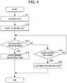
- FIG. 4 is a flowchart showing a process of control of delivery performed by the unmanned flight equipment of FIG. 1 .
- FIG. 5 is schematic side view showing a configuration of unmanned flight equipment according to a second embodiment of the present invention.
- FIG. 6 is a block diagram showing the configuration of the unmanned flight equipment of FIG. 5 .
- FIG. 7 is a schematic cross-sectional view showing a configuration of a linear member contact detection sensor included in the unmanned flight equipment of FIG. 5 .
- FIG. 1 is a schematic side view showing a configuration of unmanned flight equipment 1 according to a first embodiment of the present invention.
- FIG. 2 is a block diagram showing the configuration of the unmanned flight equipment 1 of FIG. 1 .
- the unmanned flight equipment 1 includes: an aerial vehicle 2 capable of flying in an unmanned manner; a linear member 3 configured to be suspended from the aerial vehicle 2; a container 4 held at a lower end of the linear member 3 and configured to accommodate therein a cargo W; and a winding machine 5 capable of winding the linear member 3.
- “capable of flying in an unmanned manner” refers to an aerial vehicle that can fly without any person on board the aerial vehicle, and encompasses not only an aerial vehicle capable of autonomous flight, but also an aerial vehicle remotely controlled by a person.
- the cargo W and the container 4 may be collectively referred to as the "delivery target T".
- the unmanned flight equipment 1 further includes: a contact detection unit 6 configured to detect contact of an object with the linear member 3 or with the container 4; a separation unit 7 configured to separate the linear member 3 or the container 4 from the aerial vehicle 2; a tension detection unit 8 configured to detect a pull on the linear member 3 or on the container 4; and a landing detection unit 9 configured to detect landing of the container 4 (delivery target T).
- the "object" to be detected by the contact detection unit 6 includes a person and an animal.
- the contact detection unit 6 can be configured to have: a linear member contact detection unit 10 that detects contact with at least a lower region of the linear member 3; and a container contact detection unit 11 that detects contact with the container 4.
- the contact detection unit 6 may be configured to detect contact with the linear member 3 and contact with the delivery target T while distinguishing the contact with the linear member 3 and the contact with the delivery target T from each other.
- the separation unit 7 can be configured to have: a linear member separation mechanism 12 that cuts off the linear member 3 at a point near the aerial vehicle 2 such that at least the lower region of the linear member 3 is separated; and a container separation mechanism 13 that cuts off the container 4 from the linear member 3.
- the aerial vehicle 2 is an unmanned rotorcraft including a plurality of rotors 14.
- the aerial vehicle 2 has the plurality of rotors 14 and a body 15 holding the plurality of rotors 14.
- the plurality of rotors 14 are held on the body 15 and rotate to generate lift for the unmanned flight equipment 1 to fly.
- the rotors 14 can be arranged on an upper surface of the body 15 so that they can rotate without interfering with the body 15. It is preferable that in planar view, the rotors 14 are held equidistantly from the center of the body 15 and are evenly spaced apart from each other such that their axes of rotation are vertical (and their surfaces of revolution are horizontal).
- the body 15 While holding the plurality of rotors 14, the body 15 is configured to house a battery (power source) for driving the rotors 14 and other components, and a control device 16 for controlling the flight and the like of the aerial vehicle 2.
- a battery power source
- control device 16 for controlling the flight and the like of the aerial vehicle 2.
- the control device 16 can be composed of a computer having a CPU, a memory, etc., and including appropriate programs loaded therein.
- the control device 16 can include: a flight control unit 17 for controlling the rotors; a winding control unit 18 for controlling the winding machine 5; a linear member contact determinator 19 constituting a control element of the linear member contact detection unit 10; a container contact determinator 20 constituting a control element of the container contact detection unit 11; a tension determinator 21 constituting a determination-control element of the tension detection unit 8; a landing determinator 22 constituting a determination-control element of the landing detection unit 9; and a selector 23 constituting a control element of the separation unit 7.
- These constituent elements of the control device 16 are distinguished from each other in terms of their functions, and may be indistinguishable from each other in terms of their physical configurations or program configurations.
- the linear member 3 can be constituted by a wire, for example.
- the lower region of the linear member 3 may be provided with a linear member contact detection sensor 24 that detects contact.
- the linear member contact detection sensor 24 constitutes a detector of the linear member contact detection unit 10, which will be described later.
- the linear member 3 may be used as a signal line through which signals are transmitted from the container contact detection unit 11, the linear member contact detection unit 10, the container separation mechanism 13, the tension detection unit 8 and the landing detection unit 9.
- the linear member 3 may be an insulated wire (or an insulated cable).
- the container 4 can be embodied as a box that can accommodate therein an arbitrary cargo W.
- the container 4 may include, on a top surface and a side surface thereof, a container contact detection sensor 25 that constitutes a detector of the container contact detection unit 11.
- the container 4 may further include, on a bottom surface thereof, a landing detection sensor 26 that constitutes a detector of the landing detection unit 9.
- the winding machine 5 is a winch that can wind and unwind (feed) the linear member 3.
- the winding machine 5 maintains the linear member 3 wound therearound and in contact with the body 15, thereby contributing to enhancement of stability.
- the winding machine 5 unwinds the linear member 3 to cause the delivery target T to descend to the ground while the aerial vehicle 2 is hovering in midair.
- the winding machine 5 can be configured to have a torque sensor 27 that detects a torque of the winding machine 5.
- the torque sensor 27 can constitute a detector of the tension detection unit 8.
- the contact detection unit 6 may be configured to have the linear member contact detection unit 10 that detects contact with at least the lower region of the linear member 3, and the container contact detection unit 11 that detects contact with the container 4.
- the linear member contact detection unit 10 can be configured to have the linear member contact detection sensor 24 and the linear member contact determinator 19 that determines whether or not a person or an object has come into contact with the container 4, based on a detection signal from the linear member contact detection sensor 24.
- the linear member contact detection sensor 24 examples include a pressure sensor that detects a pressure and a capacitance sensor that detects a change in capacitance.
- the linear member contact detection sensor 24 may be embodied as a capacitance sensor that has the linear member 3 with electrical conductivity and a protection cover 28 constituted by a dielectric substance and provided on the outer periphery of the linear member 3, as shown in FIG. 3 .
- the linear member contact detection sensor 24 can be configured to detect a feeble current passing through a capacitor for which the linear member 3 serves as an electrode and the body of a person serves as the other electrode.
- a current detection circuit may be provided in the body 15 of the aerial vehicle 2 or in the container 4.
- the linear member contact determinator 19 can be configured to determine that an object or the like has come into contact with the linear member 3 when a value (e.g. a current value) detected by the linear member contact detection sensor 24 exceeds a preset detection threshold.
- a value e.g. a current value
- the linear member contact determinator 19 may determine that an object or the like has come into contact with the linear member 3 when a value detected by the linear member contact detection sensor 24 continues being greater than a preset detection threshold for a period equal to or longer than a preset time threshold.
- the container contact detection unit 11 can be configured to have the container contact detection sensor 25 and the container contact determinator 20 that determines whether or not a person or an object has come into contact with the container 4, based on a detection signal from the container contact detection sensor 25.
- the container contact detection sensor 25 examples include a pressure sensor that detects a pressure and a capacitance sensor that detects a change in capacitance.
- the container contact detection sensor 25 may be embodied as a capacitance sensor that has an electrode layered on the outer surface of the container 4 and a dielectric substrate layer provided over the outer surface of the electrode. It is preferable that the container contact detection sensor 25 is provided on the top surface or the side surface of the container 4 or that the container contact detection sensor 25 covers the substantial entirety of the top and side surfaces of the container 4.
- the container contact determinator 20 can be configured to determine that an object or the like has come into contact with the container 4 when a value (e.g. a current value) detected by the container contact detection sensor 25 exceeds a preset detection threshold.
- a value e.g. a current value
- the container contact determinator 20 may determine that an object or the like has come into contact with the container 4 when a value detected by the container contact detection sensor 25 continues being greater than a preset detection threshold for a period equal to or longer than a preset time threshold.
- the separation unit 7 can be configured to have: the linear member separation mechanism 12 that cuts off the linear member 3 at a point near the aerial vehicle 2 such that at least the lower region of the linear member 3 is separated; and the container separation mechanism 13 that cuts off the container 4 from the linear member 3.
- the linear member separation mechanism 12 cuts off at least the lower region of the linear member 3 so that the lower region and the container 4 (delivery target T) are separated from the aerial vehicle 2.
- the linear member separation mechanism 12 can be configured, for example, to have a cutter for cutting the linear member 3.
- the container separation mechanism 13 cuts off the container 4 from the linear member 3 so that the container 4 is separated from the linear member 3, and consequently, the delivery target T is separated from the aerial vehicle 2.
- examples of the configuration of the container separation mechanism 13 include: a combination of a suspension ring that is provided on the top of the container 4 and an openable/closeable hook that is provided at the lower end of the linear member 3 and that is engageable with the suspension ring; and a combination of an insertion part that fits into an opening formed in the top of the container 4 and an extendable/retractable retainer nail that is provided at an end of the insertion part.
- the container separation mechanism 13 may be configured to have a movable structure that is provided at the container 4 and that can engage with and disengage from the end of the linear member 3.
- the selector 23 selectively actuates the linear member separation mechanism 12 or the container separation mechanism 13 based on the detection results of the linear member contact detection unit 10 and the container contact detection unit 11 of the contact detection unit 6, while taking account of the detection results of the tension detection unit 8 and the landing detection unit. Specifically, during the flight of the unmanned flight equipment 1, the selector 23 actuates the linear member separation mechanism 12 if the linear member contact detection unit 10 detects contact with the linear member 3 or if the tension detection unit 8 detects a tension on the linear member 3, and actuates the container separation mechanism 13 if the container contact detection unit 11 detects contact with the container 4 while the linear member contact detection unit 10 and the tension detection unit 8 do not detect the respective detection targets. If the landing detection unit 9 detects landing, the selector 23 actuates the container separation mechanism 13, as a normal operation for delivering the delivery target T.
- the tension detection unit 8 can be configured to have the torque sensor 27, and the tension determinator 21 that determines whether or not the linear member 3 has been pulled directly or via the container 4, based on a detection signal from the torque sensor 27.
- the torque sensor 27 may be constituted by a strain sensor or the like that detects torsion of a shaft of the winding machine 5.
- the tension determinator 21 can be configured to determine that the linear member 3 has been pulled when a value detected by the torque sensor 27 exceeds a preset threshold.
- the landing detection unit 9 can be configured to have the landing detection sensor 26 and the landing determinator 22 that determines whether the container 4 is in contact with the ground, based on a detection signal from the landing detection sensor 26.
- the landing detection sensor 26 may be constituted by, for example, a pressure sensor, a switch operable by the weight of the delivery target T.
- the selector 23 actuates the container separation mechanism 13 to separate the container 4 (delivery target T) from the linear member 3.
- the selector 23 actuates the linear member separation mechanism 12 to separate at least the lower region of the linear member 3 and the delivery target T from the aerial vehicle 2.
- the selector 23 separates the part contacting with the contact object (including a person and an animal) before the contact object applies a strong force to the aerial vehicle 2 via the linear member 3, thereby preventing destabilization of the flight condition of the aerial vehicle 2.
- the selector 23 may actuates the linear member separation mechanism 12 to separate at least the lower region of the linear member 3 and the delivery target T from the aerial vehicle 2.
- the selector 23 actuates the linear member separation mechanism 12 to separate the linear member 3.
- time lag time delay
- the tension detection unit 8 may detect the tension on the linear member 3 before the separation of the linear member 3 takes place.
- the linear member contact detection unit 10 cannot detect contact with the linear member 3 due to the type and condition of a contact object, the type of the sensor, etc., or due to a failure of the linear member contact detection unit 10, it is possible that the tension detection unit 8 detects a tension on the linear member 3 prior to the linear member contact detection unit 10. In these cases, it is conceivable to perform the separation of the linear member 3 as emergency control.
- the selector 23 separates the container 4 from the linear member 3 in order to deliver the delivery target T to a receiver.
- FIG. 4 shows a process of a method for delivering the delivery target T by the unmanned flight equipment 1.
- This method for delivering the delivery target T by the unmanned flight equipment 1 is a method for delivering the delivery target T by the aerial vehicle 2 capable of flying in an unmanned manner, and is per se an embodiment of the delivery method according to the present invention.
- the delivery method shown in FIG. 4 includes: causing the linear member 3 that is to be suspended from the aerial vehicle 2 to hold the delivery target T at the lower end of the linear member 3 (step S11: delivery target holding step); starting flight of the aerial vehicle 2 (step S12: flight starting step); detecting contact with the linear member 3 by the linear member contact detection unit 10 (step S13: linear member contact detecting step); separating the linear member 3 by the linear member separation mechanism 12 (step S14: linear member separating step); detecting contact with the container 4 (delivery target T) by the container contact detection unit 11 (step S15: container contact detecting step); and separating the container 4 (delivery target T) by the container separation mechanism 13 (step S16: container separating step).
- the container 4 is connected to the lower end of the linear member 3, whereby the delivery target T (with or without the cargo W) is held by the aerial vehicle 2.
- step S12 i.e., the flight starting step
- the flight of the unmanned flight equipment 1 is started. Therefore, the step S13 and the subsequent steps are performed during the flight of the aerial vehicle 2. Since the flight of the unmanned flight equipment 1 can be controlled by a well-known method, detailed description thereof will be omitted.
- the linear member contact detection unit 10 checks whether or not an object or the like has come into contact with the linear member 3. If contact with the linear member 3 is confirmed in the linear member contact detecting step, the process proceeds to the step S14, i.e., the linear member separating step. If contact with the linear member 3 is not confirmed, the process proceeds to the step S15, i.e., the container contact detecting step.
- step S14 which is the linear member separating step
- the linear member separation mechanism 12 cuts off the linear member 3 so that the lower region of the linear member 3 is separated from the aerial vehicle 2.
- the container contact detection unit 11 checks whether or not an object or the like has come into contact with the container 4. If contact with the container 4 is confirmed in the container contact detecting step, the process proceeds to the step S16, i.e., the container separating step. If contact with the container 4 is not confirmed, the process returns to the step S13, which is the linear member contact detecting step.
- the container separation mechanism 13 separates the container 4 (delivery target T) from the linear member 3.
- the delivery of the delivery target T is ended.
- the unmanned flight equipment 1 continues flying in accordance with a preset program even after the completion of delivery of the delivery target T.
- the unmanned flight equipment 1 described above separates the linear member 3 or the delivery target T so as to prevent the aerial vehicle 2 from receiving a strong external force that can be applied due to a tension acting on the linear member 3. Therefore, the unmanned flight equipment 1 is less likely to allow the attitude of the aerial vehicle 2 to be destabilized.
- a third party may pull the linear member 3 or container 4 for the sake of interest. In such a case, separating the linear member 3 or the container 4 at the moment when the person touches the linear member 3 or the container 4 makes it possible to prevent the aerial vehicle 2 from being pulled and brought into an unstable attitude.
- FIG. 5 is a schematic side view showing a configuration of the unmanned flight equipment 1A according to the second embodiment of the present invention.
- FIG. 6 is a block diagram showing the configuration of the unmanned flight equipment 1A of FIG. 5 .
- the unmanned flight equipment 1A includes: an aerial vehicle 2A capable of flying in an unmanned manner; a linear member 3 configured to be suspended from the aerial vehicle 2A; a container 4 held at a lower end of the linear member 3 and configured to accommodate therein a cargo W (the cargo W and the container 4 may be collectively referred to as the "delivery target T"); a winding machine 5 capable of winding the linear member 3; a contact detection unit 6A configured to detect contact of an object (including a person and an animal) with the linear member 3 or the container 4; a separation unit 7A configured to separate the linear member 3 or the container 4 from the aerial vehicle 2A; a tension detection unit 8 configured to detect a pull on the linear member 3 or the container 4; a landing detection unit 9 configured to detect landing of the container 4; and a contact object discrimination unit 29 configured to discriminate the type of a contact object contacting with the linear member 3 or the container 4.
- the same components as those of the unmanned flight equipment 1A of the second embodiment the same components as those of the
- the aerial vehicle 2A has a control device 16A that controls flight and constitutes control elements of the contact detection unit 6A, the separation unit 7A, the tension detection unit 8, the landing detection unit 9 and the contact object discrimination unit 29.
- the contact detection unit 6A can be configured to have: a linear member contact detection unit 10A that detects contact with at least a lower region of the linear member 3; and a container contact detection unit 11 that detects contact with the container 4.
- the linear member contact detection unit 10A can be configured to have a linear member contact detection sensor 24A and a linear member contact determinator 19.
- the linear member contact detection sensor 24A may be configured to have a sensitive layer 30 that is provided on the outer periphery of the linear member 3 and is made of an insulating elastomeric matrix containing a large number of carbon microcoils dispersed therein. Due to the large number of carbon microcoils contained therein, the sensitive layer 30 can be electrically considered to be a distributed constant circuit in which a plurality of resistors, capacitors and inductors are complexly combined. When an external force is applied to a portion of the sensitive layer 30, since the carbon microcoils present in the portion are deformed and moved, the electrical characteristics of the sensitive layer 30 change in a highly sensitive manner.
- the linear member contact detection unit 10A detects a change in the electric characteristics of the sensitive layer 30 caused by a feeble contact pressure that is applied by contact of an object with the linear member contact detection sensor 24A, thereby detecting the contact of the object with the linear member 3.
- a detection circuit may be provided in the body 15 of the aerial vehicle 2A or in the container 4.
- the separation unit 7A can be configured to have: a linear member separation mechanism 12 that cuts off the linear member 3 at a point near the aerial vehicle 2A such that at least a lower region of the linear member 3 is separated; a container separation mechanism 13 that cuts off the container 4 from the linear member 3; and a selector 23A.
- the selector 23A selectively actuates one of the linear member separation mechanism 12 and the container separation mechanism 13 based on the determination results of the linear member contact detection unit 10A, the container contact detection unit 11, the tension detection unit 8, the landing detection unit 9 and the contact object discrimination unit 29. Even in the case where the linear member contact detection unit 10A or the container contact detection unit 11 detects contact, if the contact object discriminated by the contact object discrimination unit 29 is considered to be an object that does not destabilize the flight of the aerial vehicle 2, such as a small object (including a small animal), the selector 23A may keep the linear member separation mechanism 12 and the container separation mechanism 13 inactive.
- the selector 23A may actuate the separation unit 7A with reference to a correspondence table describing operations of the separation unit 7A, that is, correspondences between the determination results of the contact object discrimination unit 29, whether to actuate the linear member separation mechanism 12 or the container separation mechanism 13, and whether to keep both mechanisms 12 and 13 inactive.
- the contact object discrimination unit 29 can be configured to have: a camera 31 that is held on the aerial vehicle 2A and captures an image of a view below the camera 31; and a type determinator 32 that determines the type of a contact object contacting with the linear member 3 or the container 4 based on the image captured by the camera 31.
- the contact object discrimination unit 29 can be configured to discriminate the type of a contact object based on the size and shape of the contact object in the captured image.
- the unmanned flight equipment 1A which is provided with the contact object discrimination unit 29, can separate the delivery target T more appropriately, and thereby can prevent destabilization of the flight of the aerial vehicle 2A.
- each of the embodiments of the present invention achieves advantageous effects due to the following configurations.
- the unmanned flight equipment (1, 1A) includes: the aerial vehicle (2, 2A) capable of flying in an unmanned manner; the linear member (3) configured to be suspended from the aerial vehicle (2, 2A) and to hold the delivery target (T: the container 4 and the cargo W) at the lower end thereof; the contact detection unit (6, 6A) configured to detect contact with the delivery target (T: the container 4) or contact with the linear member (3); and the separation unit (7, 7A) configured to separate the delivery target (T) or the linear member (3) based on the detection result of the contact detection unit (6, 6A).
- the delivery target (T) or the linear member (3) is separated from the aerial vehicle (2, 2A) before a contact object applies a strong external force to the aerial vehicle (2, 2A) via the linear member (3), whereby the flight condition of the aerial vehicle (2, 2A) is prevented from being destabilized.
- the separation unit (7A) has the selector (23A) that selects whether to separate only the delivery target (T) or to separate the linear member (3) together with the delivery target (T). With this feature, the unmanned flight equipment (1A) can separate the delivery target (T) more appropriately, and can prevent destabilization of the flight of the aerial vehicle (2A) more reliably.
- the unmanned flight equipment (1A) further includes the contact object discrimination unit (29) configured to discriminate a type of a contact object whose contact has been detected by the contact detection unit (6A), and the separation unit (7A) selects whether to separate only the delivery target (T) or to separate the linear member (3) together with the delivery target (T), in accordance with the type of the contact object.
- This feature enables the unmanned flight equipment (1A) to separate the delivery target (T) only when the separation is intended, thereby preventing destabilization of the flight of the aerial vehicle (2A).
- the contact detection unit (6) detects contact with the delivery target (T) and contact with the linear member (3) while distinguishing the contact with the delivery target (T) and the contact with the linear member (3) from each other.
- the separation unit (7A) selects whether to separate only the delivery target (T) or to separate the linear member (3) together with the delivery target (T), in accordance with the type of contact object. This feature enables the unmanned flight equipment (1, 1A) to separate the delivery target (T) only when the separation is intended, whereby the flight of the aerial vehicle (2A) can be prevented from being destabilized.
- the contact detection unit (6, 6A) detects contact with the top surface or side surface of the delivery target (T). This feature makes it possible to detect contact involving high probability that an external force will act on the delivery target (T) and the aerial vehicle (2, 2A) will be pulled.
- the unmanned flight equipment (1, 1A) further includes the tension detection unit (8) that detects a pull on the delivery target (T) or the linear member (3), and the separation unit (7, 7A) separates the delivery target (T) or the linear member (3) while taking account of a detection result of the tension detection unit (8).
- the separation unit (7, 7A) has: the container separation mechanism (13) that separates the delivery target (T); the linear member separation mechanism (12) that separates the linear member (3); and the selector (23) that actuate either the container separation mechanism (13) or the linear member separation mechanism (12) based on the detection result of the contact detection unit (6, 6A) and the detection result of the tension detection unit (8).
- the unmanned flight equipment (1, 1A) further includes the landing detection unit (9) configured to detect landing of the delivery target.
- the separation unit (7, 7A) separates the delivery target (T) or the linear member (3) while taking account of a detection result of the landing detection unit (9). This feature makes it possible to deliver the delivery target (T) without dropping the delivery target (T) in normal delivery.
- the delivery target (T) includes the container (4) held at the lower end of the linear member (3) and configured to accommodate therein the cargo (W). This feature makes it easy for the contact detection unit (6) to detect contact with delivery target (T).
- the contact detection unit (6, 6A) includes the contact detection sensor (24, 24A) that is configured to detect contact with at least the lower region of the linear member (3). This feature enables reliable detection of contact with the linear member (3) .
- the contact detection sensor (24) is a capacitance sensor that detects a change in capacitance. This feature makes it possible to detect contact with the linear member (3) relatively easily.
- the contact detection sensor (24A) includes carbon microcoils. This feature enables fine detection of contact with the linear member (3).
- the method for delivering the delivery target (T) by the aerial vehicle (2) capable of flying in an unmanned manner includes: causing the linear member (3) that is to be suspended from the aerial vehicle (2) to hold the delivery target (T) at the lower end thereof; detecting contact with the delivery target (T) or contact with the linear member (3) during flight of the aerial vehicle (2); and separating the delivery target (T) or the linear member (3) based on a detection result obtained in the detecting contact.
- the delivery target (T) or the linear member (3) is separated from the aerial vehicle (2) before the contact object applies a strong force to the aerial vehicle (2) via the linear member (3), thereby preventing the flight conditions of the aerial vehicle (2) from being destabilized.
- the aerial vehicle is not limited to an unmanned rotorcraft, but may be, for example, an airship or the like.
- the delivery target may be any article, examples of which include arbitrary instruments such as a camera and a sensor.
- the delivery target does not have to include the container, and may be directly held at the lower end of the linear member using, for example, a binding band.
- the unmanned flight equipment of the present invention may exclude the winding machine, and the upper end of the linear member may be connected to the aerial vehicle.
- the contact detection unit detects contact with at least one of the linear member or the container, while having configuration with only one of the linear member contact detection unit and the container contact detection unit, for example.
- the contact detection unit may be configured to have an image-based contact detector that detects the presence or absence of contact with the linear member or the delivery target from an image captured by a camera.
- Such an image-based contact detector may be used alone or in combination with a detection unit, such as the linear member contact detection unit and the container contact detection unit, which uses a contact detection sensor.
- the tension detection unit and the landing detection unit may be omitted.
- the separation unit has at least one of the container separation mechanism and the linear member separation mechanism.
- the separation unit preferably includes the linear member separation mechanism.
- the configuration of the linear member contact detection sensor is not limited to the configurations described in the above embodiments, and may be any configuration as long as it can detect contact of an object.
- the electrode of the linear member contact detection sensor may be a conductive layer provided on the outer periphery of the linear member.
- the linear member contact detection sensor may have an electrode also on the outer peripheral side.
- the type determinator may be configured to determine the type of a contact object based on information provided from a sensor or the like other than a camera.
- the type determinator may have a three-dimensional distance sensor or the like.
- the type determinator may be configured to be integral with the contact detection unit.
- the contact detection unit has a contact detection sensor including carbon microcoils, previously storing a relationship between tendencies to change of the electrical characteristics of the sensitive layer and the types of contact objects enables detection of contact and determination of the type of a contact object.
- the constituent elements relating to the control of the contact detection unit, the separation unit, the tension detection unit and the landing detection unit are implemented by the control device housed in the body.
- the control device housed in the body.
- at least part of these constituent elements relating to the control may be configured to be independent, or may be attached to or incorporated in a physical constituent element such as a sensor or a separation mechanism.
Landscapes
- Engineering & Computer Science (AREA)
- Aviation & Aerospace Engineering (AREA)
- Forklifts And Lifting Vehicles (AREA)
- Warehouses Or Storage Devices (AREA)
Abstract
Description
- The present invention relates to unmanned flight equipment and a delivery method.
- It has been under consideration to use an aerial vehicle that can fly in an unmanned manner, such as the so-called drone, to deliver a cargo. Such an aerial vehicle is provided with a box or the like for accommodating a cargo, and the cargo is delivered to a receiver while the box is opened in a state where the aerial vehicle is on the ground. In this case, a flat place having at least a certain area that allows the aerial vehicle to land is used as a place for delivering the cargo.
- In view of this, as disclosed in
Patent Documents - In the case where a delivery target is held by a linear member suspended from an aerial vehicle, an external force such as wind may act on the delivery target or the linear member so as to destabilize the flight state of the aerial vehicle. Therefore, the unmanned flight equipment disclosed in
Patent Document 1 includes an adjustment means at a fixing device that fixes a string-like member to a body of the aerial vehicle, the adjustment means adjusting the way of fixing the string-like member in accordance with an attitude of the body such that the center of gravity of the body is on the extension of the vertical line of the string-like member having a cargo hung thereon. As a result, the load of the cargo constantly acts on the center of gravity of the aerial vehicle, thereby enabling the unmanned flight equipment ofPatent Document 1 to fly stably. - The delivery apparatus disclosed in
Patent Document 2 includes an unmanned aircraft, a main wire suspended from a body of the unmanned aircraft, and an auxiliary wire coupled to a portion of the main wire located toward a fixed end with respect to a free end of the main wire, the auxiliary wire extending along the main wire and having an end located outside with respect to the free end of the main wire. This delivery apparatus is configured such that an operator attaches a cargo to the end of the auxiliary wire while the auxiliary wire is loose, so that a situation can be avoided in which the operator destabilizes the attitude of the unmanned aircraft by pulling the main wire when attaching the cargo. - Patent Document 1: Japanese Unexamined Patent Application, Publication No.
2018-90095 - Patent Document 2: Japanese Unexamined Patent Application, Publication No.
2017-87898 - With the configuration of
Patent Document 1, when the string-like member is pulled, for example, it is impossible for the aerial vehicle to maintain its attitude. With the configuration ofPatent Document 2, while it is possible to prevent the main wire from being pulled when a cargo is attached, when the cargo is delivered (when the cargo is detached from the auxiliary wire), the main wire is pulled, thereby making it impossible to prevent the attitude of the unmanned aircraft from being destabilized. - One or more embodiments of the present invention has been conceived in view of the forgoing background, and an object of one or more embodiments of the present invention are directed to provide unmanned flight equipment including an aerial vehicle of which an attitude is unlikely to be destabilized by an external force acting on a linear member suspended from the aerial vehicle or on a cargo.
- Unmanned flight equipment according to an aspect of the present invention includes: an aerial vehicle capable of flying in an unmanned manner; a linear member configured to be suspended from the aerial vehicle and to hold a delivery target at a lower end thereof; a contact detection unit configured to detect contact with the delivery target or contact with the linear member; and a separation unit configured to separate the delivery target or the liner member based on a detection result of the contact detection unit.
- A delivery method according to another aspect of one or more embodiments of the present invention is a method for delivering a delivery target by an aerial vehicle capable of flying in an unmanned manner. The delivery method includes: causing a linear member that is to be suspended from the aerial vehicle to hold the delivery target at a lower end of the linear member; detecting contact with the delivery target or contact with the linear member during flight of the aerial vehicle; and separating the delivery target or the linear member based on a detection result obtained in the detecting contact.
- The present invention provides unmanned flight equipment including an aerial vehicle of which an attitude is unlikely to be destabilized by an external force acting on a linear member suspended from the aerial vehicle or on a cargo.
-
FIG. 1 is schematic side view showing a configuration of unmanned flight equipment according to a first embodiment of the present invention.FIG. 2 is a block diagram showing the configuration of the unmanned flight equipment ofFIG. 1 .FIG. 3 is a schematic cross-sectional view showing a configuration of a linear member contact detection sensor included in the unmanned flight equipment ofFIG. 1 .FIG. 4 is a flowchart showing a process of control of delivery performed by the unmanned flight equipment ofFIG. 1 .FIG. 5 is schematic side view showing a configuration of unmanned flight equipment according to a second embodiment of the present invention.FIG. 6 is a block diagram showing the configuration of the unmanned flight equipment ofFIG. 5 .FIG. 7 is a schematic cross-sectional view showing a configuration of a linear member contact detection sensor included in the unmanned flight equipment ofFIG. 5 . - Non-limiting exemplary embodiments of the present invention will be described with reference to the drawings.
FIG. 1 is a schematic side view showing a configuration ofunmanned flight equipment 1 according to a first embodiment of the present invention.FIG. 2 is a block diagram showing the configuration of theunmanned flight equipment 1 ofFIG. 1 . - As shown in
FIG. 1 , theunmanned flight equipment 1 includes: anaerial vehicle 2 capable of flying in an unmanned manner; alinear member 3 configured to be suspended from theaerial vehicle 2; acontainer 4 held at a lower end of thelinear member 3 and configured to accommodate therein a cargo W; and awinding machine 5 capable of winding thelinear member 3. It should be noted that "capable of flying in an unmanned manner" refers to an aerial vehicle that can fly without any person on board the aerial vehicle, and encompasses not only an aerial vehicle capable of autonomous flight, but also an aerial vehicle remotely controlled by a person. The cargo W and thecontainer 4 may be collectively referred to as the "delivery target T". - As shown in
FIG. 2 , theunmanned flight equipment 1 further includes: acontact detection unit 6 configured to detect contact of an object with thelinear member 3 or with thecontainer 4; aseparation unit 7 configured to separate thelinear member 3 or thecontainer 4 from theaerial vehicle 2; atension detection unit 8 configured to detect a pull on thelinear member 3 or on thecontainer 4; and alanding detection unit 9 configured to detect landing of the container 4 (delivery target T). The "object" to be detected by thecontact detection unit 6 includes a person and an animal. - The
contact detection unit 6 can be configured to have: a linear membercontact detection unit 10 that detects contact with at least a lower region of thelinear member 3; and a containercontact detection unit 11 that detects contact with thecontainer 4. In other words, thecontact detection unit 6 may be configured to detect contact with thelinear member 3 and contact with the delivery target T while distinguishing the contact with thelinear member 3 and the contact with the delivery target T from each other. Theseparation unit 7 can be configured to have: a linearmember separation mechanism 12 that cuts off thelinear member 3 at a point near theaerial vehicle 2 such that at least the lower region of thelinear member 3 is separated; and acontainer separation mechanism 13 that cuts off thecontainer 4 from thelinear member 3. - The components of the
unmanned flight equipment 1 will be described below. First, theaerial vehicle 2 will be described. While theaerial vehicle 2 is not limited to any particular vehicle as long as it can fly in an unmanned manner, theaerial vehicle 2 of the present embodiment shown in the drawings is an unmanned rotorcraft including a plurality ofrotors 14. Specifically, theaerial vehicle 2 has the plurality ofrotors 14 and abody 15 holding the plurality ofrotors 14. - The plurality of
rotors 14 are held on thebody 15 and rotate to generate lift for theunmanned flight equipment 1 to fly. Therotors 14 can be arranged on an upper surface of thebody 15 so that they can rotate without interfering with thebody 15. It is preferable that in planar view, therotors 14 are held equidistantly from the center of thebody 15 and are evenly spaced apart from each other such that their axes of rotation are vertical (and their surfaces of revolution are horizontal). - While holding the plurality of
rotors 14, thebody 15 is configured to house a battery (power source) for driving therotors 14 and other components, and acontrol device 16 for controlling the flight and the like of theaerial vehicle 2. - The
control device 16 can be composed of a computer having a CPU, a memory, etc., and including appropriate programs loaded therein. Thecontrol device 16 can include: aflight control unit 17 for controlling the rotors; awinding control unit 18 for controlling thewinding machine 5; a linearmember contact determinator 19 constituting a control element of the linear membercontact detection unit 10; acontainer contact determinator 20 constituting a control element of the containercontact detection unit 11; atension determinator 21 constituting a determination-control element of thetension detection unit 8; alanding determinator 22 constituting a determination-control element of thelanding detection unit 9; and aselector 23 constituting a control element of theseparation unit 7. These constituent elements of thecontrol device 16 are distinguished from each other in terms of their functions, and may be indistinguishable from each other in terms of their physical configurations or program configurations. - The
linear member 3 can be constituted by a wire, for example. The lower region of thelinear member 3 may be provided with a linear membercontact detection sensor 24 that detects contact. The linear membercontact detection sensor 24 constitutes a detector of the linear membercontact detection unit 10, which will be described later. Thelinear member 3 may be used as a signal line through which signals are transmitted from the containercontact detection unit 11, the linear membercontact detection unit 10, thecontainer separation mechanism 13, thetension detection unit 8 and thelanding detection unit 9. Thus, thelinear member 3 may be an insulated wire (or an insulated cable). - The
container 4 can be embodied as a box that can accommodate therein an arbitrary cargo W. Thecontainer 4 may include, on a top surface and a side surface thereof, a containercontact detection sensor 25 that constitutes a detector of the containercontact detection unit 11. Thecontainer 4 may further include, on a bottom surface thereof, alanding detection sensor 26 that constitutes a detector of thelanding detection unit 9. - The winding
machine 5 is a winch that can wind and unwind (feed) thelinear member 3. When theunmanned flight equipment 1 flies at a high speed, the windingmachine 5 maintains thelinear member 3 wound therearound and in contact with thebody 15, thereby contributing to enhancement of stability. The windingmachine 5 unwinds thelinear member 3 to cause the delivery target T to descend to the ground while theaerial vehicle 2 is hovering in midair. - The winding
machine 5 can be configured to have atorque sensor 27 that detects a torque of the windingmachine 5. Thetorque sensor 27 can constitute a detector of thetension detection unit 8. - As described earlier, the
contact detection unit 6 may be configured to have the linear membercontact detection unit 10 that detects contact with at least the lower region of thelinear member 3, and the containercontact detection unit 11 that detects contact with thecontainer 4. - The linear member
contact detection unit 10 can be configured to have the linear membercontact detection sensor 24 and the linearmember contact determinator 19 that determines whether or not a person or an object has come into contact with thecontainer 4, based on a detection signal from the linear membercontact detection sensor 24. - Examples of the linear member
contact detection sensor 24 include a pressure sensor that detects a pressure and a capacitance sensor that detects a change in capacitance. For example, the linear membercontact detection sensor 24 may be embodied as a capacitance sensor that has thelinear member 3 with electrical conductivity and a protection cover 28 constituted by a dielectric substance and provided on the outer periphery of thelinear member 3, as shown inFIG. 3 . The linear membercontact detection sensor 24 can be configured to detect a feeble current passing through a capacitor for which thelinear member 3 serves as an electrode and the body of a person serves as the other electrode. A current detection circuit may be provided in thebody 15 of theaerial vehicle 2 or in thecontainer 4. - The linear
member contact determinator 19 can be configured to determine that an object or the like has come into contact with thelinear member 3 when a value (e.g. a current value) detected by the linear membercontact detection sensor 24 exceeds a preset detection threshold. Alternatively, in order not to detect temporary contact of a small piece of trash or the like blown by a wind, the linearmember contact determinator 19 may determine that an object or the like has come into contact with thelinear member 3 when a value detected by the linear membercontact detection sensor 24 continues being greater than a preset detection threshold for a period equal to or longer than a preset time threshold. - The container
contact detection unit 11 can be configured to have the containercontact detection sensor 25 and thecontainer contact determinator 20 that determines whether or not a person or an object has come into contact with thecontainer 4, based on a detection signal from the containercontact detection sensor 25. - Examples of the container
contact detection sensor 25 include a pressure sensor that detects a pressure and a capacitance sensor that detects a change in capacitance. Specifically, the containercontact detection sensor 25 may be embodied as a capacitance sensor that has an electrode layered on the outer surface of thecontainer 4 and a dielectric substrate layer provided over the outer surface of the electrode. It is preferable that the containercontact detection sensor 25 is provided on the top surface or the side surface of thecontainer 4 or that the containercontact detection sensor 25 covers the substantial entirety of the top and side surfaces of thecontainer 4. - Like the linear
member contact determinator 19, thecontainer contact determinator 20 can be configured to determine that an object or the like has come into contact with thecontainer 4 when a value (e.g. a current value) detected by the containercontact detection sensor 25 exceeds a preset detection threshold. Alternatively, in order not to detect temporary contact of a small piece of trash or the like blown by a wind, thecontainer contact determinator 20 may determine that an object or the like has come into contact with thecontainer 4 when a value detected by the containercontact detection sensor 25 continues being greater than a preset detection threshold for a period equal to or longer than a preset time threshold. - As described earlier, the
separation unit 7 can be configured to have: the linearmember separation mechanism 12 that cuts off thelinear member 3 at a point near theaerial vehicle 2 such that at least the lower region of thelinear member 3 is separated; and thecontainer separation mechanism 13 that cuts off thecontainer 4 from thelinear member 3. - The linear
member separation mechanism 12 cuts off at least the lower region of thelinear member 3 so that the lower region and the container 4 (delivery target T) are separated from theaerial vehicle 2. Specifically, the linearmember separation mechanism 12 can be configured, for example, to have a cutter for cutting thelinear member 3. - The
container separation mechanism 13 cuts off thecontainer 4 from thelinear member 3 so that thecontainer 4 is separated from thelinear member 3, and consequently, the delivery target T is separated from theaerial vehicle 2. Specifically, examples of the configuration of thecontainer separation mechanism 13 include: a combination of a suspension ring that is provided on the top of thecontainer 4 and an openable/closeable hook that is provided at the lower end of thelinear member 3 and that is engageable with the suspension ring; and a combination of an insertion part that fits into an opening formed in the top of thecontainer 4 and an extendable/retractable retainer nail that is provided at an end of the insertion part. Alternatively, thecontainer separation mechanism 13 may be configured to have a movable structure that is provided at thecontainer 4 and that can engage with and disengage from the end of thelinear member 3. - The
selector 23 selectively actuates the linearmember separation mechanism 12 or thecontainer separation mechanism 13 based on the detection results of the linear membercontact detection unit 10 and the containercontact detection unit 11 of thecontact detection unit 6, while taking account of the detection results of thetension detection unit 8 and the landing detection unit. Specifically, during the flight of theunmanned flight equipment 1, theselector 23 actuates the linearmember separation mechanism 12 if the linear membercontact detection unit 10 detects contact with thelinear member 3 or if thetension detection unit 8 detects a tension on thelinear member 3, and actuates thecontainer separation mechanism 13 if the containercontact detection unit 11 detects contact with thecontainer 4 while the linear membercontact detection unit 10 and thetension detection unit 8 do not detect the respective detection targets. If thelanding detection unit 9 detects landing, theselector 23 actuates thecontainer separation mechanism 13, as a normal operation for delivering the delivery target T. - The
tension detection unit 8 can be configured to have thetorque sensor 27, and thetension determinator 21 that determines whether or not thelinear member 3 has been pulled directly or via thecontainer 4, based on a detection signal from thetorque sensor 27. - The
torque sensor 27 may be constituted by a strain sensor or the like that detects torsion of a shaft of the windingmachine 5. - The tension determinator 21 can be configured to determine that the
linear member 3 has been pulled when a value detected by thetorque sensor 27 exceeds a preset threshold. - The
landing detection unit 9 can be configured to have thelanding detection sensor 26 and thelanding determinator 22 that determines whether thecontainer 4 is in contact with the ground, based on a detection signal from thelanding detection sensor 26. - The
landing detection sensor 26 may be constituted by, for example, a pressure sensor, a switch operable by the weight of the delivery target T. - When the container
contact detection unit 11 detects contact, theselector 23 actuates thecontainer separation mechanism 13 to separate the container 4 (delivery target T) from thelinear member 3. When the linear membercontact detection unit 10 detects contact, theselector 23 actuates the linearmember separation mechanism 12 to separate at least the lower region of thelinear member 3 and the delivery target T from theaerial vehicle 2. In other words, when a person or an animal actively interferes with thelinear member 3 and/or thecontainer 4, or when thelinear member 3 and/or thecontainer 4 are/is caught by a tree, a building, etc., theselector 23 separates the part contacting with the contact object (including a person and an animal) before the contact object applies a strong force to theaerial vehicle 2 via thelinear member 3, thereby preventing destabilization of the flight condition of theaerial vehicle 2. - When the
tension detection unit 8 detects a tension on thelinear member 3, theselector 23 may actuates the linearmember separation mechanism 12 to separate at least the lower region of thelinear member 3 and the delivery target T from theaerial vehicle 2. As described earlier, when the linear membercontact detection unit 10 detects contact with thelinear member 3, theselector 23 actuates the linearmember separation mechanism 12 to separate thelinear member 3. Here, if thelinear member 3 is separated before a tension acts on thelinear member 3, thetension detection unit 8 will no longer detect a tension on thelinear member 3. However, there is a time delay (time lag) between detection of contact and separation of thelinear member 3 since it takes time to perform associated processing and to drive the linearmember separation mechanism 12. Therefore, depending on the speed at which the contact object causes a tension to act on the linear member 3 (e.g., if the speed is very high), thetension detection unit 8 may detect the tension on thelinear member 3 before the separation of thelinear member 3 takes place. In addition, if the linear membercontact detection unit 10 cannot detect contact with thelinear member 3 due to the type and condition of a contact object, the type of the sensor, etc., or due to a failure of the linear membercontact detection unit 10, it is possible that thetension detection unit 8 detects a tension on thelinear member 3 prior to the linear membercontact detection unit 10. In these cases, it is conceivable to perform the separation of thelinear member 3 as emergency control. - In addition, when the landing detection unit detects landing of the
container 4, theselector 23 separates thecontainer 4 from thelinear member 3 in order to deliver the delivery target T to a receiver. -
FIG. 4 shows a process of a method for delivering the delivery target T by theunmanned flight equipment 1. This method for delivering the delivery target T by theunmanned flight equipment 1 is a method for delivering the delivery target T by theaerial vehicle 2 capable of flying in an unmanned manner, and is per se an embodiment of the delivery method according to the present invention. - The delivery method shown in
FIG. 4 includes: causing thelinear member 3 that is to be suspended from theaerial vehicle 2 to hold the delivery target T at the lower end of the linear member 3 (step S11: delivery target holding step); starting flight of the aerial vehicle 2 (step S12: flight starting step); detecting contact with thelinear member 3 by the linear member contact detection unit 10 (step S13: linear member contact detecting step); separating thelinear member 3 by the linear member separation mechanism 12 (step S14: linear member separating step); detecting contact with the container 4 (delivery target T) by the container contact detection unit 11 (step S15: container contact detecting step); and separating the container 4 (delivery target T) by the container separation mechanism 13 (step S16: container separating step). - In the step S11, i.e., the delivery target holding step, the
container 4 is connected to the lower end of thelinear member 3, whereby the delivery target T (with or without the cargo W) is held by theaerial vehicle 2. - In the step S12, i.e., the flight starting step, the flight of the
unmanned flight equipment 1 is started. Therefore, the step S13 and the subsequent steps are performed during the flight of theaerial vehicle 2. Since the flight of theunmanned flight equipment 1 can be controlled by a well-known method, detailed description thereof will be omitted. - In the step S13, i.e., the linear member contact detecting step, the linear member
contact detection unit 10 checks whether or not an object or the like has come into contact with thelinear member 3. If contact with thelinear member 3 is confirmed in the linear member contact detecting step, the process proceeds to the step S14, i.e., the linear member separating step. If contact with thelinear member 3 is not confirmed, the process proceeds to the step S15, i.e., the container contact detecting step. - In the step S14, which is the linear member separating step, the linear
member separation mechanism 12 cuts off thelinear member 3 so that the lower region of thelinear member 3 is separated from theaerial vehicle 2. - In the step S15, i.e., the container contact detecting step, the container
contact detection unit 11 checks whether or not an object or the like has come into contact with thecontainer 4. If contact with thecontainer 4 is confirmed in the container contact detecting step, the process proceeds to the step S16, i.e., the container separating step. If contact with thecontainer 4 is not confirmed, the process returns to the step S13, which is the linear member contact detecting step. - In the step S16, i.e., the container separating step, the
container separation mechanism 13 separates the container 4 (delivery target T) from thelinear member 3. - When the linear member separating step as the step S14 or the container separating step as the step S16 is performed, the delivery of the delivery target T is ended. The
unmanned flight equipment 1 continues flying in accordance with a preset program even after the completion of delivery of the delivery target T. - When it is determined that an object or the like has come into contact with the
linear member 3 or thecontainer 4, theunmanned flight equipment 1 described above separates thelinear member 3 or the delivery target T so as to prevent theaerial vehicle 2 from receiving a strong external force that can be applied due to a tension acting on thelinear member 3. Therefore, theunmanned flight equipment 1 is less likely to allow the attitude of theaerial vehicle 2 to be destabilized. In particular, when the delivery of the cargo W takes place in a place where many people are present, a third party may pull thelinear member 3 orcontainer 4 for the sake of interest. In such a case, separating thelinear member 3 or thecontainer 4 at the moment when the person touches thelinear member 3 or thecontainer 4 makes it possible to prevent theaerial vehicle 2 from being pulled and brought into an unstable attitude. - Next, unmanned flight equipment 1A according to a second embodiment of the present invention will be described.
FIG. 5 is a schematic side view showing a configuration of the unmanned flight equipment 1A according to the second embodiment of the present invention.FIG. 6 is a block diagram showing the configuration of the unmanned flight equipment 1A ofFIG. 5 . - The unmanned flight equipment 1A includes: an
aerial vehicle 2A capable of flying in an unmanned manner; alinear member 3 configured to be suspended from theaerial vehicle 2A; acontainer 4 held at a lower end of thelinear member 3 and configured to accommodate therein a cargo W (the cargo W and thecontainer 4 may be collectively referred to as the "delivery target T"); a windingmachine 5 capable of winding thelinear member 3; acontact detection unit 6A configured to detect contact of an object (including a person and an animal) with thelinear member 3 or thecontainer 4; aseparation unit 7A configured to separate thelinear member 3 or thecontainer 4 from theaerial vehicle 2A; atension detection unit 8 configured to detect a pull on thelinear member 3 or thecontainer 4; alanding detection unit 9 configured to detect landing of thecontainer 4; and a contactobject discrimination unit 29 configured to discriminate the type of a contact object contacting with thelinear member 3 or thecontainer 4. Note that in the following description of the unmanned flight equipment 1A of the second embodiment, the same components as those of theunmanned flight equipment 1 of the first embodiment will be denoted by the same reference characters, and the description thereof will not be repeated. - The
aerial vehicle 2A has acontrol device 16A that controls flight and constitutes control elements of thecontact detection unit 6A, theseparation unit 7A, thetension detection unit 8, thelanding detection unit 9 and the contactobject discrimination unit 29. - The
contact detection unit 6A can be configured to have: a linear membercontact detection unit 10A that detects contact with at least a lower region of thelinear member 3; and a containercontact detection unit 11 that detects contact with thecontainer 4. The linear membercontact detection unit 10A can be configured to have a linear membercontact detection sensor 24A and a linearmember contact determinator 19. - As shown in
FIG. 7 , the linear membercontact detection sensor 24A may be configured to have asensitive layer 30 that is provided on the outer periphery of thelinear member 3 and is made of an insulating elastomeric matrix containing a large number of carbon microcoils dispersed therein. Due to the large number of carbon microcoils contained therein, thesensitive layer 30 can be electrically considered to be a distributed constant circuit in which a plurality of resistors, capacitors and inductors are complexly combined. When an external force is applied to a portion of thesensitive layer 30, since the carbon microcoils present in the portion are deformed and moved, the electrical characteristics of thesensitive layer 30 change in a highly sensitive manner. For this reason, the linear membercontact detection unit 10A detects a change in the electric characteristics of thesensitive layer 30 caused by a feeble contact pressure that is applied by contact of an object with the linear membercontact detection sensor 24A, thereby detecting the contact of the object with thelinear member 3. A detection circuit may be provided in thebody 15 of theaerial vehicle 2A or in thecontainer 4. - The
separation unit 7A can be configured to have: a linearmember separation mechanism 12 that cuts off thelinear member 3 at a point near theaerial vehicle 2A such that at least a lower region of thelinear member 3 is separated; acontainer separation mechanism 13 that cuts off thecontainer 4 from thelinear member 3; and aselector 23A. - The
selector 23A selectively actuates one of the linearmember separation mechanism 12 and thecontainer separation mechanism 13 based on the determination results of the linear membercontact detection unit 10A, the containercontact detection unit 11, thetension detection unit 8, thelanding detection unit 9 and the contactobject discrimination unit 29. Even in the case where the linear membercontact detection unit 10A or the containercontact detection unit 11 detects contact, if the contact object discriminated by the contactobject discrimination unit 29 is considered to be an object that does not destabilize the flight of theaerial vehicle 2, such as a small object (including a small animal), theselector 23A may keep the linearmember separation mechanism 12 and thecontainer separation mechanism 13 inactive. Thus, theselector 23A may actuate theseparation unit 7A with reference to a correspondence table describing operations of theseparation unit 7A, that is, correspondences between the determination results of the contactobject discrimination unit 29, whether to actuate the linearmember separation mechanism 12 or thecontainer separation mechanism 13, and whether to keep bothmechanisms - The contact
object discrimination unit 29 can be configured to have: acamera 31 that is held on theaerial vehicle 2A and captures an image of a view below thecamera 31; and atype determinator 32 that determines the type of a contact object contacting with thelinear member 3 or thecontainer 4 based on the image captured by thecamera 31. For example, the contactobject discrimination unit 29 can be configured to discriminate the type of a contact object based on the size and shape of the contact object in the captured image. - As can be seen, the unmanned flight equipment 1A, which is provided with the contact
object discrimination unit 29, can separate the delivery target T more appropriately, and thereby can prevent destabilization of the flight of theaerial vehicle 2A. - As described above, each of the embodiments of the present invention achieves advantageous effects due to the following configurations.
- The unmanned flight equipment (1, 1A) includes: the aerial vehicle (2, 2A) capable of flying in an unmanned manner; the linear member (3) configured to be suspended from the aerial vehicle (2, 2A) and to hold the delivery target (T: the
container 4 and the cargo W) at the lower end thereof; the contact detection unit (6, 6A) configured to detect contact with the delivery target (T: the container 4) or contact with the linear member (3); and the separation unit (7, 7A) configured to separate the delivery target (T) or the linear member (3) based on the detection result of the contact detection unit (6, 6A). With this configuration, the delivery target (T) or the linear member (3) is separated from the aerial vehicle (2, 2A) before a contact object applies a strong external force to the aerial vehicle (2, 2A) via the linear member (3), whereby the flight condition of the aerial vehicle (2, 2A) is prevented from being destabilized. - In the unmanned flight equipment (1A), the separation unit (7A) has the selector (23A) that selects whether to separate only the delivery target (T) or to separate the linear member (3) together with the delivery target (T). With this feature, the unmanned flight equipment (1A) can separate the delivery target (T) more appropriately, and can prevent destabilization of the flight of the aerial vehicle (2A) more reliably.
- The unmanned flight equipment (1A) further includes the contact object discrimination unit (29) configured to discriminate a type of a contact object whose contact has been detected by the contact detection unit (6A), and the separation unit (7A) selects whether to separate only the delivery target (T) or to separate the linear member (3) together with the delivery target (T), in accordance with the type of the contact object. This feature enables the unmanned flight equipment (1A) to separate the delivery target (T) only when the separation is intended, thereby preventing destabilization of the flight of the aerial vehicle (2A).
- In the unmanned flight equipment (1, 1A), the contact detection unit (6) detects contact with the delivery target (T) and contact with the linear member (3) while distinguishing the contact with the delivery target (T) and the contact with the linear member (3) from each other. The separation unit (7A) selects whether to separate only the delivery target (T) or to separate the linear member (3) together with the delivery target (T), in accordance with the type of contact object. This feature enables the unmanned flight equipment (1, 1A) to separate the delivery target (T) only when the separation is intended, whereby the flight of the aerial vehicle (2A) can be prevented from being destabilized.
- In the unmanned flight equipment (1, 1A), the contact detection unit (6, 6A) detects contact with the top surface or side surface of the delivery target (T). This feature makes it possible to detect contact involving high probability that an external force will act on the delivery target (T) and the aerial vehicle (2, 2A) will be pulled.
- The unmanned flight equipment (1, 1A) further includes the tension detection unit (8) that detects a pull on the delivery target (T) or the linear member (3), and the separation unit (7, 7A) separates the delivery target (T) or the linear member (3) while taking account of a detection result of the tension detection unit (8). Specifically, the separation unit (7, 7A) has: the container separation mechanism (13) that separates the delivery target (T); the linear member separation mechanism (12) that separates the linear member (3); and the selector (23) that actuate either the container separation mechanism (13) or the linear member separation mechanism (12) based on the detection result of the contact detection unit (6, 6A) and the detection result of the tension detection unit (8). As a result, even in the event that the contact detection unit (6, 6A) cannot detect contact properly, the delivery target (T) or the linear member (3) is separated, whereby the aerial vehicle (2, 2A) is prevented from being pulled strongly.
- The unmanned flight equipment (1, 1A) further includes the landing detection unit (9) configured to detect landing of the delivery target. The separation unit (7, 7A) separates the delivery target (T) or the linear member (3) while taking account of a detection result of the landing detection unit (9). This feature makes it possible to deliver the delivery target (T) without dropping the delivery target (T) in normal delivery.
- In the unmanned flight equipment (1, 1A), the delivery target (T) includes the container (4) held at the lower end of the linear member (3) and configured to accommodate therein the cargo (W). This feature makes it easy for the contact detection unit (6) to detect contact with delivery target (T).
- In the unmanned flight equipment (1, 1A), the contact detection unit (6, 6A) includes the contact detection sensor (24, 24A) that is configured to detect contact with at least the lower region of the linear member (3). This feature enables reliable detection of contact with the linear member (3) .
- In the unmanned flight equipment (1), the contact detection sensor (24) is a capacitance sensor that detects a change in capacitance. This feature makes it possible to detect contact with the linear member (3) relatively easily.
- In the unmanned flight equipment (1A), the contact detection sensor (24A) includes carbon microcoils. This feature enables fine detection of contact with the linear member (3).
- The method for delivering the delivery target (T) by the aerial vehicle (2) capable of flying in an unmanned manner includes: causing the linear member (3) that is to be suspended from the aerial vehicle (2) to hold the delivery target (T) at the lower end thereof; detecting contact with the delivery target (T) or contact with the linear member (3) during flight of the aerial vehicle (2); and separating the delivery target (T) or the linear member (3) based on a detection result obtained in the detecting contact. As a result, when an object comes into contact with the delivery target (T) or the linear member (3), the delivery target (T) or the linear member (3) is separated from the aerial vehicle (2) before the contact object applies a strong force to the aerial vehicle (2) via the linear member (3), thereby preventing the flight conditions of the aerial vehicle (2) from being destabilized.
- Two embodiments of the present invention have been described in the foregoing. However, the present invention is not limited to the above-described embodiments, but encompasses variations, improvements, and the like within the scope allowing achievement of the object of the present invention.
- In unmanned flight equipment according to an embodiment of the present invention, the aerial vehicle is not limited to an unmanned rotorcraft, but may be, for example, an airship or the like. In unmanned flight equipment according to an embodiment of the present invention, the delivery target may be any article, examples of which include arbitrary instruments such as a camera and a sensor. The delivery target does not have to include the container, and may be directly held at the lower end of the linear member using, for example, a binding band. The unmanned flight equipment of the present invention may exclude the winding machine, and the upper end of the linear member may be connected to the aerial vehicle.
- In unmanned flight equipment according to an embodiment of the present invention, it is suitable that the contact detection unit detects contact with at least one of the linear member or the container, while having configuration with only one of the linear member contact detection unit and the container contact detection unit, for example. The contact detection unit may be configured to have an image-based contact detector that detects the presence or absence of contact with the linear member or the delivery target from an image captured by a camera. Such an image-based contact detector may be used alone or in combination with a detection unit, such as the linear member contact detection unit and the container contact detection unit, which uses a contact detection sensor.
- In unmanned flight equipment according to an embodiment of the present invention, the tension detection unit and the landing detection unit may be omitted. Further, in unmanned flight equipment according to an embodiment of the present invention, it is suitable that the separation unit has at least one of the container separation mechanism and the linear member separation mechanism. In this case, the separation unit preferably includes the linear member separation mechanism.
- In unmanned flight equipment according to an embodiment of the present invention, the configuration of the linear member contact detection sensor is not limited to the configurations described in the above embodiments, and may be any configuration as long as it can detect contact of an object. For example, the electrode of the linear member contact detection sensor may be a conductive layer provided on the outer periphery of the linear member. Alternatively, the linear member contact detection sensor may have an electrode also on the outer peripheral side.
- In unmanned flight equipment according to an embodiment of the present invention, the type determinator may be configured to determine the type of a contact object based on information provided from a sensor or the like other than a camera. For example, the type determinator may have a three-dimensional distance sensor or the like. The type determinator may be configured to be integral with the contact detection unit. For example, in the case where the contact detection unit has a contact detection sensor including carbon microcoils, previously storing a relationship between tendencies to change of the electrical characteristics of the sensitive layer and the types of contact objects enables detection of contact and determination of the type of a contact object.
- In the unmanned flight equipment according to each of the above-described embodiments, the constituent elements relating to the control of the contact detection unit, the separation unit, the tension detection unit and the landing detection unit are implemented by the control device housed in the body. However, at least part of these constituent elements relating to the control may be configured to be independent, or may be attached to or incorporated in a physical constituent element such as a sensor or a separation mechanism.
-
- 1, 1A:
- Unmanned Flight Equipment
- 2, 2A:
- Aerial Vehicle
- 3:
- Linear Member
- 4:
- Container
- 5:
- Winding Machine
- 6, 6A:
- Contact Detection Unit
- 7, 7A:
- Separation Unit
- 8:
- Tension Detection Unit
- 9:
- Landing Detection Unit
- 10, 10A:
- Linear Member Contact Detection Unit
- 11:
- Container Contact Detection Unit
- 12:
- Linear Member Separation Mechanism
- 13:
- Container Separation Mechanism
- 14:
- Rotor
- 15:
- Body
- 16, 16A:
- Control Device
- 17:
- Flight Control Unit
- 18:
- Winding Control Unit
- 19:
- Linear Member Contact Determinator
- 20:
- Container Contact Determinator
- 21:
- Tension Determinator
- 22:
- Landing Determinator
- 23, 23A:
- Selector
- 24, 24A:
- Linear Member Contact Detection Sensor
- 25:
- Container Contact Detection Sensor
- 26:
- Landing Detection Sensor
- 27:
- Torque Sensor
- 28:
- Protection Cover
- 29:
- Contact Object Discrimination Unit
- 30:
- Sensitive Layer
- 31:
- Camera
- 32:
- Type Determinator
- C:
- Carbon Microcoil
- T:
- Delivery Target
- W:
- Cargo
Claims (12)
- Unmanned flight equipment comprising:an aerial vehicle capable of flying in an unmanned manner;a linear member configured to be suspended from the aerial vehicle and to hold a delivery target at a lower end thereof;a contact detection unit configured to detect contact with the delivery target or contact with the linear member; anda separation unit configured to separate the delivery target or the liner member based on a detection result of the contact detection unit.
- The unmanned flight equipment according to claim 1, wherein
the separation unit has a selector configured to select whether to separate only the delivery target or to separate the linear member together with the delivery target. - The unmanned flight equipment according to claim 2, further comprising:a contact target discrimination unit configured to discriminate a type of a contact object whose contact has been detected by the contact detection unit, whereinthe selector selects whether to separate only the delivery target or to separate the linear member together with the delivery target, in accordance with the type of the contact object.
- The unmanned flight equipment according to claim 2 or 3, wherein
the contact detection unit detects contact with the delivery target and contact with the linear member while distinguishing the contact with the delivery target and the contact with the linear member from each other, and
the selector selects whether to separate only the delivery target or to separate the linear member together with the delivery target, in accordance with which of the contact with the delivery target and the contact with the linear member has been detected. - The unmanned flight equipment according to any one of claims 1 to 4, wherein
the contact detection unit detects contact with a top surface or a side surface of the delivery target. - The unmanned flight equipment according to any one of claims 1 to 5, further comprising:a tension detection unit configured to detect a pull on the delivery target or on the linear member, whereinthe separation unit separates the delivery target or the linear member while taking account of a detection result of the tension detection unit.
- The unmanned flight equipment according to any one of claims 1 to 6, further comprising:a landing detection unit configured to detect landing of the delivery target, whereinthe separation unit separates the delivery target or the linear member while taking account of a detection result of the landing detection unit.
- The unmanned flight equipment according to any one of claims 1 to 7, wherein
the delivery target includes a container held at the lower end of the linear member and configured to accommodate therein a cargo. - The unmanned flight equipment according to any one of claims 1 to 8, wherein
the contact detection unit includes a linear member contact detection sensor that is configured to detect contact with at least a lower region of the linear member. - The unmanned flight equipment according to claim 9, wherein
the linear member contact detection sensor is a capacitance sensor that detects a change in capacitance. - The unmanned flight equipment according to claim 9, wherein
the linear member contact detection sensor includes a carbon microcoil. - A method for delivering a delivery target by an aerial vehicle capable of flying in an unmanned manner, the method comprising:causing a linear member that is to be suspended from the aerial vehicle to hold the delivery target at a lower end of the linear member;detecting contact with the delivery target or contact with the linear member during flight of the aerial vehicle; andseparating the delivery target or the linear member based on a detection result obtained in the detecting contact.
Applications Claiming Priority (1)
| Application Number | Priority Date | Filing Date | Title |
|---|---|---|---|
| PCT/JP2019/013774 WO2020194707A1 (en) | 2019-03-28 | 2019-03-28 | Unmanned flight device and transport method |
Publications (3)
| Publication Number | Publication Date |
|---|---|
| EP3741673A1 true EP3741673A1 (en) | 2020-11-25 |
| EP3741673A4 EP3741673A4 (en) | 2020-11-25 |
| EP3741673B1 EP3741673B1 (en) | 2024-10-09 |
Family
ID=71663981
Family Applications (1)
| Application Number | Title | Priority Date | Filing Date |
|---|---|---|---|
| EP19864003.9A Active EP3741673B1 (en) | 2019-03-28 | 2019-03-28 | Unmanned flight device and transport method |
Country Status (4)
| Country | Link |
|---|---|
| US (1) | US11548635B2 (en) |
| EP (1) | EP3741673B1 (en) |
| JP (1) | JP6727466B1 (en) |
| WO (1) | WO2020194707A1 (en) |
Families Citing this family (5)
| Publication number | Priority date | Publication date | Assignee | Title |
|---|---|---|---|---|
| CN115809839B (en) * | 2018-03-14 | 2026-07-31 | 联邦快递公司 | Method for performing store-to-consumer logistics operations |
| US12380754B2 (en) | 2021-02-25 | 2025-08-05 | Federal Express Corporation | Methods and apparatus for providing enhanced automated access to a dispatched personal delivery device operative to transport a shipment item |
| WO2023286146A1 (en) * | 2021-07-13 | 2023-01-19 | 株式会社エアロネクスト | Flying vehicle |
| US11884397B2 (en) | 2022-04-14 | 2024-01-30 | Workhorse Group Inc. | Unmanned aerial vehicle delivery systems |
| CN118977854B (en) * | 2024-10-21 | 2025-01-28 | 四川观想科技股份有限公司 | UAV payload mounting device |
Family Cites Families (18)
| Publication number | Priority date | Publication date | Assignee | Title |
|---|---|---|---|---|
| US9346547B2 (en) * | 2013-08-26 | 2016-05-24 | Google Inc. | Mechanisms for lowering a payload to the ground from a UAV |
| US10839336B2 (en) * | 2013-12-26 | 2020-11-17 | Flir Detection, Inc. | Unmanned delivery |
| US9321531B1 (en) * | 2014-07-08 | 2016-04-26 | Google Inc. | Bystander interaction during delivery from aerial vehicle |
| US9174733B1 (en) | 2014-08-28 | 2015-11-03 | Google Inc. | Payload-release device and operation thereof |
| US9688404B1 (en) * | 2014-12-02 | 2017-06-27 | Amazon Technologies, Inc. | Stabilized airborne drop delivery |
| CA2999486A1 (en) | 2015-09-23 | 2017-03-30 | Walmart Apollo, Llc | Package release system for use in delivery packages, and methods of delivering packages |
| US9969494B1 (en) * | 2015-09-28 | 2018-05-15 | Amazon Technologies, Inc. | Delivery drop platforms, tethers, and stabilization |
| US10071804B1 (en) * | 2015-09-28 | 2018-09-11 | Amazon Technologies, Inc. | Delivery drop rate modulation |
| KR101818307B1 (en) * | 2015-10-20 | 2018-02-22 | 성균관대학교산학협력단 | Tactile sensor possible to detect a proximity |
| JP6393888B2 (en) | 2015-11-06 | 2018-09-26 | 株式会社プロドローン | Conveying equipment |
| JP6393887B2 (en) * | 2015-11-06 | 2018-09-26 | 株式会社プロドローン | Transport device and transport method |
| KR101825584B1 (en) * | 2016-01-13 | 2018-02-05 | (주)창성 | Touch panel having carbon micro coil tactile sensor |
| US11104438B2 (en) * | 2016-09-09 | 2021-08-31 | Wing Aviation Llc | Payload coupling apparatus for UAV and method of delivering a payload |
| US10793274B2 (en) * | 2016-09-09 | 2020-10-06 | Wing Aviation Llc | Payload coupling apparatus for UAV and method of delivering a payload |
| JP2018090095A (en) | 2016-12-02 | 2018-06-14 | 株式会社エンルートM’s | Unmanned flight apparatus, luggage transport method and program |
| KR102444407B1 (en) * | 2017-04-19 | 2022-09-20 | 엘지이노텍 주식회사 | detection device |
| GB201808075D0 (en) * | 2017-09-13 | 2018-07-04 | Flirtey Holdings Inc | Unmanned aerial vehicle and payload delivery system |
| US20190235494A1 (en) * | 2018-01-31 | 2019-08-01 | Walmart Apollo, Llc | System and method for defending an unmanned aerial vehicle from ground threats |
-
2019
- 2019-03-28 EP EP19864003.9A patent/EP3741673B1/en active Active
- 2019-03-28 US US16/753,066 patent/US11548635B2/en active Active
- 2019-03-28 JP JP2019572235A patent/JP6727466B1/en active Active
- 2019-03-28 WO PCT/JP2019/013774 patent/WO2020194707A1/en not_active Ceased
Also Published As
| Publication number | Publication date |
|---|---|
| JP6727466B1 (en) | 2020-07-22 |
| EP3741673B1 (en) | 2024-10-09 |
| US20210221508A1 (en) | 2021-07-22 |
| US11548635B2 (en) | 2023-01-10 |
| EP3741673A4 (en) | 2020-11-25 |
| WO2020194707A1 (en) | 2020-10-01 |
| JPWO2020194707A1 (en) | 2021-04-08 |
Similar Documents
| Publication | Publication Date | Title |
|---|---|---|
| US11548635B2 (en) | Unmanned flight equipment and delivery method | |
| US12017774B2 (en) | Unmanned aerial vehicle, aerial vehicle control system and transportation method | |
| US10358217B2 (en) | Human transporting drone | |
| US9302770B2 (en) | Payload-release device and operation thereof | |
| EP3889042B1 (en) | Unmanned aerial device, load-lowering device, and method of transporting a load | |
| US11745874B2 (en) | Unmanned aerial vehicle recovery systems and methods | |
| US12179922B2 (en) | Unmanned aircraft system, control device and control method | |
| US20100004803A1 (en) | Smart recovery system | |
| US20210179265A1 (en) | Unmanned aerial vehicle, aerial vehicle control system and transportation method | |
| JP7331234B2 (en) | AIRCRAFT, CONTROL METHOD AND CONTROL DEVICE | |
| JP7275612B2 (en) | Aircraft landing port and aircraft landing method | |
| US20240166382A1 (en) | Drone parachute systems for delivery or recovery | |
| US12606327B2 (en) | Operation system of unmanned aircraft | |
| CN114502463B (en) | Control method and device of unmanned aerial vehicle system, unmanned aerial vehicle system and storage medium | |
| CN106941777A (en) | Unmanned plane and its carry device, carry platform, control method and control system | |
| CN205801534U (en) | The carry device of unmanned plane and unmanned plane | |
| JP7227333B2 (en) | AIRCRAFT, CONTROL METHOD AND CONTROL DEVICE | |
| JP7000633B1 (en) | Aircraft, control methods, and controls | |
| WO2021161685A1 (en) | Flying device and parachute device | |
| JP6616492B2 (en) | Delivery management device, delivery management system, and delivery management method | |
| US10457416B2 (en) | Parachute landing assistant | |
| WO2016059953A1 (en) | Electric power supply system | |
| EP3345855A1 (en) | Single-wire transmission of sensor data | |
| Farman | A semi-automatic parachute separation system for balloon payloads | |
| JP2019188946A (en) | Unmanned aerial vehicle |
Legal Events
| Date | Code | Title | Description |
|---|---|---|---|
| STAA | Information on the status of an ep patent application or granted ep patent |
Free format text: STATUS: UNKNOWN |
|
| STAA | Information on the status of an ep patent application or granted ep patent |
Free format text: STATUS: THE INTERNATIONAL PUBLICATION HAS BEEN MADE |
|
| PUAI | Public reference made under article 153(3) epc to a published international application that has entered the european phase |
Free format text: ORIGINAL CODE: 0009012 |
|
| STAA | Information on the status of an ep patent application or granted ep patent |
Free format text: STATUS: REQUEST FOR EXAMINATION WAS MADE |
|
| 17P | Request for examination filed |
Effective date: 20200402 |
|
| A4 | Supplementary search report drawn up and despatched |
Effective date: 20200916 |
|
| AK | Designated contracting states |
Kind code of ref document: A1 Designated state(s): AL AT BE BG CH CY CZ DE DK EE ES FI FR GB GR HR HU IE IS IT LI LT LU LV MC MK MT NL NO PL PT RO RS SE SI SK SM TR |
|
| AX | Request for extension of the european patent |
Extension state: BA ME |
|
| RAP3 | Party data changed (applicant data changed or rights of an application transferred) |
Owner name: RAKUTEN GROUP, INC. |
|
| STAA | Information on the status of an ep patent application or granted ep patent |
Free format text: STATUS: EXAMINATION IS IN PROGRESS |
|
| 17Q | First examination report despatched |
Effective date: 20210927 |
|
| DAV | Request for validation of the european patent (deleted) | ||
| DAX | Request for extension of the european patent (deleted) | ||
| REG | Reference to a national code |
Ref country code: DE Free format text: PREVIOUS MAIN CLASS: B64C0039020000 Ref country code: DE Ref legal event code: R079 Ref document number: 602019060259 Country of ref document: DE Free format text: PREVIOUS MAIN CLASS: B64C0039020000 Ipc: B64U0101640000 |
|
| GRAP | Despatch of communication of intention to grant a patent |
Free format text: ORIGINAL CODE: EPIDOSNIGR1 |
|
| STAA | Information on the status of an ep patent application or granted ep patent |
Free format text: STATUS: GRANT OF PATENT IS INTENDED |
|
| RIC1 | Information provided on ipc code assigned before grant |
Ipc: B64D 1/12 20060101ALI20240415BHEP Ipc: B64U 101/67 20230101ALI20240415BHEP Ipc: B64U 101/64 20230101AFI20240415BHEP |
|
| INTG | Intention to grant announced |
Effective date: 20240517 |
|
| GRAS | Grant fee paid |
Free format text: ORIGINAL CODE: EPIDOSNIGR3 |
|
| GRAA | (expected) grant |
Free format text: ORIGINAL CODE: 0009210 |
|
| STAA | Information on the status of an ep patent application or granted ep patent |
Free format text: STATUS: THE PATENT HAS BEEN GRANTED |
|
| AK | Designated contracting states |
Kind code of ref document: B1 Designated state(s): AL AT BE BG CH CY CZ DE DK EE ES FI FR GB GR HR HU IE IS IT LI LT LU LV MC MK MT NL NO PL PT RO RS SE SI SK SM TR |
|
| REG | Reference to a national code |
Ref country code: CH Ref legal event code: EP |
|
| REG | Reference to a national code |
Ref country code: DE Ref legal event code: R096 Ref document number: 602019060259 Country of ref document: DE |
|
| REG | Reference to a national code |
Ref country code: IE Ref legal event code: FG4D |
|
| REG | Reference to a national code |
Ref country code: LT Ref legal event code: MG9D |
|
| REG | Reference to a national code |
Ref country code: NL Ref legal event code: MP Effective date: 20241009 |
|
| REG | Reference to a national code |
Ref country code: AT Ref legal event code: MK05 Ref document number: 1730366 Country of ref document: AT Kind code of ref document: T Effective date: 20241009 |
|
| PG25 | Lapsed in a contracting state [announced via postgrant information from national office to epo] |
Ref country code: NL Free format text: LAPSE BECAUSE OF FAILURE TO SUBMIT A TRANSLATION OF THE DESCRIPTION OR TO PAY THE FEE WITHIN THE PRESCRIBED TIME-LIMIT Effective date: 20241009 |
|
| PG25 | Lapsed in a contracting state [announced via postgrant information from national office to epo] |
Ref country code: NL Free format text: LAPSE BECAUSE OF FAILURE TO SUBMIT A TRANSLATION OF THE DESCRIPTION OR TO PAY THE FEE WITHIN THE PRESCRIBED TIME-LIMIT Effective date: 20241009 |
|
| PG25 | Lapsed in a contracting state [announced via postgrant information from national office to epo] |
Ref country code: IS Free format text: LAPSE BECAUSE OF FAILURE TO SUBMIT A TRANSLATION OF THE DESCRIPTION OR TO PAY THE FEE WITHIN THE PRESCRIBED TIME-LIMIT Effective date: 20250209 Ref country code: PT Free format text: LAPSE BECAUSE OF FAILURE TO SUBMIT A TRANSLATION OF THE DESCRIPTION OR TO PAY THE FEE WITHIN THE PRESCRIBED TIME-LIMIT Effective date: 20250210 Ref country code: HR Free format text: LAPSE BECAUSE OF FAILURE TO SUBMIT A TRANSLATION OF THE DESCRIPTION OR TO PAY THE FEE WITHIN THE PRESCRIBED TIME-LIMIT Effective date: 20241009 |
|
| PG25 | Lapsed in a contracting state [announced via postgrant information from national office to epo] |
Ref country code: FI Free format text: LAPSE BECAUSE OF FAILURE TO SUBMIT A TRANSLATION OF THE DESCRIPTION OR TO PAY THE FEE WITHIN THE PRESCRIBED TIME-LIMIT Effective date: 20241009 |
|
| PG25 | Lapsed in a contracting state [announced via postgrant information from national office to epo] |
Ref country code: BG Free format text: LAPSE BECAUSE OF FAILURE TO SUBMIT A TRANSLATION OF THE DESCRIPTION OR TO PAY THE FEE WITHIN THE PRESCRIBED TIME-LIMIT Effective date: 20241009 |
|
| PG25 | Lapsed in a contracting state [announced via postgrant information from national office to epo] |
Ref country code: ES Free format text: LAPSE BECAUSE OF FAILURE TO SUBMIT A TRANSLATION OF THE DESCRIPTION OR TO PAY THE FEE WITHIN THE PRESCRIBED TIME-LIMIT Effective date: 20241009 |
|
| PG25 | Lapsed in a contracting state [announced via postgrant information from national office to epo] |
Ref country code: NO Free format text: LAPSE BECAUSE OF FAILURE TO SUBMIT A TRANSLATION OF THE DESCRIPTION OR TO PAY THE FEE WITHIN THE PRESCRIBED TIME-LIMIT Effective date: 20250109 |
|
| PG25 | Lapsed in a contracting state [announced via postgrant information from national office to epo] |
Ref country code: AT Free format text: LAPSE BECAUSE OF FAILURE TO SUBMIT A TRANSLATION OF THE DESCRIPTION OR TO PAY THE FEE WITHIN THE PRESCRIBED TIME-LIMIT Effective date: 20241009 Ref country code: LV Free format text: LAPSE BECAUSE OF FAILURE TO SUBMIT A TRANSLATION OF THE DESCRIPTION OR TO PAY THE FEE WITHIN THE PRESCRIBED TIME-LIMIT Effective date: 20241009 Ref country code: GR Free format text: LAPSE BECAUSE OF FAILURE TO SUBMIT A TRANSLATION OF THE DESCRIPTION OR TO PAY THE FEE WITHIN THE PRESCRIBED TIME-LIMIT Effective date: 20250110 |
|
| PG25 | Lapsed in a contracting state [announced via postgrant information from national office to epo] |
Ref country code: PL Free format text: LAPSE BECAUSE OF FAILURE TO SUBMIT A TRANSLATION OF THE DESCRIPTION OR TO PAY THE FEE WITHIN THE PRESCRIBED TIME-LIMIT Effective date: 20241009 |
|
| PG25 | Lapsed in a contracting state [announced via postgrant information from national office to epo] |
Ref country code: RS Free format text: LAPSE BECAUSE OF FAILURE TO SUBMIT A TRANSLATION OF THE DESCRIPTION OR TO PAY THE FEE WITHIN THE PRESCRIBED TIME-LIMIT Effective date: 20250109 |
|
| PG25 | Lapsed in a contracting state [announced via postgrant information from national office to epo] |
Ref country code: SM Free format text: LAPSE BECAUSE OF FAILURE TO SUBMIT A TRANSLATION OF THE DESCRIPTION OR TO PAY THE FEE WITHIN THE PRESCRIBED TIME-LIMIT Effective date: 20241009 |
|
| PG25 | Lapsed in a contracting state [announced via postgrant information from national office to epo] |
Ref country code: DK Free format text: LAPSE BECAUSE OF FAILURE TO SUBMIT A TRANSLATION OF THE DESCRIPTION OR TO PAY THE FEE WITHIN THE PRESCRIBED TIME-LIMIT Effective date: 20241009 |
|
| REG | Reference to a national code |
Ref country code: DE Ref legal event code: R097 Ref document number: 602019060259 Country of ref document: DE |
|
| PG25 | Lapsed in a contracting state [announced via postgrant information from national office to epo] |
Ref country code: EE Free format text: LAPSE BECAUSE OF FAILURE TO SUBMIT A TRANSLATION OF THE DESCRIPTION OR TO PAY THE FEE WITHIN THE PRESCRIBED TIME-LIMIT Effective date: 20241009 |
|
| PG25 | Lapsed in a contracting state [announced via postgrant information from national office to epo] |
Ref country code: RO Free format text: LAPSE BECAUSE OF FAILURE TO SUBMIT A TRANSLATION OF THE DESCRIPTION OR TO PAY THE FEE WITHIN THE PRESCRIBED TIME-LIMIT Effective date: 20241009 |
|
| PG25 | Lapsed in a contracting state [announced via postgrant information from national office to epo] |
Ref country code: SK Free format text: LAPSE BECAUSE OF FAILURE TO SUBMIT A TRANSLATION OF THE DESCRIPTION OR TO PAY THE FEE WITHIN THE PRESCRIBED TIME-LIMIT Effective date: 20241009 |
|
| PG25 | Lapsed in a contracting state [announced via postgrant information from national office to epo] |
Ref country code: CZ Free format text: LAPSE BECAUSE OF FAILURE TO SUBMIT A TRANSLATION OF THE DESCRIPTION OR TO PAY THE FEE WITHIN THE PRESCRIBED TIME-LIMIT Effective date: 20241009 |
|
| PG25 | Lapsed in a contracting state [announced via postgrant information from national office to epo] |
Ref country code: IT Free format text: LAPSE BECAUSE OF FAILURE TO SUBMIT A TRANSLATION OF THE DESCRIPTION OR TO PAY THE FEE WITHIN THE PRESCRIBED TIME-LIMIT Effective date: 20241009 |
|
| PLBE | No opposition filed within time limit |
Free format text: ORIGINAL CODE: 0009261 |
|
| STAA | Information on the status of an ep patent application or granted ep patent |
Free format text: STATUS: NO OPPOSITION FILED WITHIN TIME LIMIT |
|
| PG25 | Lapsed in a contracting state [announced via postgrant information from national office to epo] |
Ref country code: SE Free format text: LAPSE BECAUSE OF FAILURE TO SUBMIT A TRANSLATION OF THE DESCRIPTION OR TO PAY THE FEE WITHIN THE PRESCRIBED TIME-LIMIT Effective date: 20241009 |
|
| 26N | No opposition filed |
Effective date: 20250710 |
|
| PG25 | Lapsed in a contracting state [announced via postgrant information from national office to epo] |
Ref country code: MC Free format text: LAPSE BECAUSE OF FAILURE TO SUBMIT A TRANSLATION OF THE DESCRIPTION OR TO PAY THE FEE WITHIN THE PRESCRIBED TIME-LIMIT Effective date: 20241009 |
|
| REG | Reference to a national code |
Ref country code: CH Ref legal event code: H13 Free format text: ST27 STATUS EVENT CODE: U-0-0-H10-H13 (AS PROVIDED BY THE NATIONAL OFFICE) Effective date: 20251023 |
|
| PG25 | Lapsed in a contracting state [announced via postgrant information from national office to epo] |
Ref country code: LU Free format text: LAPSE BECAUSE OF NON-PAYMENT OF DUE FEES Effective date: 20250328 |
|
| REG | Reference to a national code |
Ref country code: BE Ref legal event code: MM Effective date: 20250331 |
|
| PG25 | Lapsed in a contracting state [announced via postgrant information from national office to epo] |
Ref country code: BE Free format text: LAPSE BECAUSE OF NON-PAYMENT OF DUE FEES Effective date: 20250331 |
|
| PG25 | Lapsed in a contracting state [announced via postgrant information from national office to epo] |
Ref country code: CH Free format text: LAPSE BECAUSE OF NON-PAYMENT OF DUE FEES Effective date: 20250331 |
|
| PG25 | Lapsed in a contracting state [announced via postgrant information from national office to epo] |
Ref country code: IE Free format text: LAPSE BECAUSE OF NON-PAYMENT OF DUE FEES Effective date: 20250328 |
|
| PGFP | Annual fee paid to national office [announced via postgrant information from national office to epo] |
Ref country code: GB Payment date: 20260219 Year of fee payment: 8 |
|
| PGFP | Annual fee paid to national office [announced via postgrant information from national office to epo] |
Ref country code: DE Payment date: 20260219 Year of fee payment: 8 |
|
| PGFP | Annual fee paid to national office [announced via postgrant information from national office to epo] |
Ref country code: FR Payment date: 20260219 Year of fee payment: 8 |
|
| PG25 | Lapsed in a contracting state [announced via postgrant information from national office to epo] |
Ref country code: CY Free format text: LAPSE BECAUSE OF FAILURE TO SUBMIT A TRANSLATION OF THE DESCRIPTION OR TO PAY THE FEE WITHIN THE PRESCRIBED TIME-LIMIT Effective date: 20241009 |
|
| PG25 | Lapsed in a contracting state [announced via postgrant information from national office to epo] |
Ref country code: LT Free format text: LAPSE BECAUSE OF FAILURE TO SUBMIT A TRANSLATION OF THE DESCRIPTION OR TO PAY THE FEE WITHIN THE PRESCRIBED TIME-LIMIT Effective date: 20241009 |
|
| PG25 | Lapsed in a contracting state [announced via postgrant information from national office to epo] |
Ref country code: TR Free format text: LAPSE BECAUSE OF FAILURE TO SUBMIT A TRANSLATION OF THE DESCRIPTION OR TO PAY THE FEE WITHIN THE PRESCRIBED TIME-LIMIT Effective date: 20241009 |