EP3741535A1 - Lining material peeling method - Google Patents
Lining material peeling method Download PDFInfo
- Publication number
- EP3741535A1 EP3741535A1 EP18900709.9A EP18900709A EP3741535A1 EP 3741535 A1 EP3741535 A1 EP 3741535A1 EP 18900709 A EP18900709 A EP 18900709A EP 3741535 A1 EP3741535 A1 EP 3741535A1
- Authority
- EP
- European Patent Office
- Prior art keywords
- lining material
- liquid nitrogen
- nozzle unit
- base
- peeling method
- Prior art date
- Legal status (The legal status is an assumption and is not a legal conclusion. Google has not performed a legal analysis and makes no representation as to the accuracy of the status listed.)
- Granted
Links
Images






Classifications
-
- B—PERFORMING OPERATIONS; TRANSPORTING
- B32—LAYERED PRODUCTS
- B32B—LAYERED PRODUCTS, i.e. PRODUCTS BUILT-UP OF STRATA OF FLAT OR NON-FLAT, e.g. CELLULAR OR HONEYCOMB, FORM
- B32B43/00—Operations specially adapted for layered products and not otherwise provided for, e.g. repairing; Apparatus therefor
- B32B43/006—Delaminating
-
- B—PERFORMING OPERATIONS; TRANSPORTING
- B05—SPRAYING OR ATOMISING IN GENERAL; APPLYING FLUENT MATERIALS TO SURFACES, IN GENERAL
- B05D—PROCESSES FOR APPLYING FLUENT MATERIALS TO SURFACES, IN GENERAL
- B05D3/00—Pretreatment of surfaces to which liquids or other fluent materials are to be applied; After-treatment of applied coatings, e.g. intermediate treating of an applied coating preparatory to subsequent applications of liquids or other fluent materials
- B05D3/12—Pretreatment of surfaces to which liquids or other fluent materials are to be applied; After-treatment of applied coatings, e.g. intermediate treating of an applied coating preparatory to subsequent applications of liquids or other fluent materials by mechanical means
-
- B—PERFORMING OPERATIONS; TRANSPORTING
- B29—WORKING OF PLASTICS; WORKING OF SUBSTANCES IN A PLASTIC STATE IN GENERAL
- B29B—PREPARATION OR PRETREATMENT OF THE MATERIAL TO BE SHAPED; MAKING GRANULES OR PREFORMS; RECOVERY OF PLASTICS OR OTHER CONSTITUENTS OF WASTE MATERIAL CONTAINING PLASTICS
- B29B17/00—Recovery of plastics or other constituents of waste material containing plastics
- B29B17/02—Separating plastics from other materials
-
- B—PERFORMING OPERATIONS; TRANSPORTING
- B29—WORKING OF PLASTICS; WORKING OF SUBSTANCES IN A PLASTIC STATE IN GENERAL
- B29C—SHAPING OR JOINING OF PLASTICS; SHAPING OF MATERIAL IN A PLASTIC STATE, NOT OTHERWISE PROVIDED FOR; AFTER-TREATMENT OF THE SHAPED PRODUCTS, e.g. REPAIRING
- B29C63/00—Lining or sheathing, i.e. applying preformed layers or sheathings of plastics; Apparatus therefor
- B29C63/0004—Component parts, details or accessories; Auxiliary operations
- B29C63/0013—Removing old coatings
-
- B—PERFORMING OPERATIONS; TRANSPORTING
- B24—GRINDING; POLISHING
- B24C—ABRASIVE OR RELATED BLASTING WITH PARTICULATE MATERIAL
- B24C1/00—Methods for use of abrasive blasting for producing particular effects; Use of auxiliary equipment in connection with such methods
- B24C1/003—Methods for use of abrasive blasting for producing particular effects; Use of auxiliary equipment in connection with such methods using material which dissolves or changes phase after the treatment, e.g. ice, CO2
-
- B—PERFORMING OPERATIONS; TRANSPORTING
- B24—GRINDING; POLISHING
- B24C—ABRASIVE OR RELATED BLASTING WITH PARTICULATE MATERIAL
- B24C1/00—Methods for use of abrasive blasting for producing particular effects; Use of auxiliary equipment in connection with such methods
- B24C1/08—Methods for use of abrasive blasting for producing particular effects; Use of auxiliary equipment in connection with such methods for polishing surfaces, e.g. smoothing a surface by making use of liquid-borne abrasives
- B24C1/086—Descaling; Removing coating films
-
- B—PERFORMING OPERATIONS; TRANSPORTING
- B24—GRINDING; POLISHING
- B24C—ABRASIVE OR RELATED BLASTING WITH PARTICULATE MATERIAL
- B24C3/00—Abrasive blasting machines or devices; Plants
- B24C3/02—Abrasive blasting machines or devices; Plants characterised by the arrangement of the component assemblies with respect to each other
- B24C3/06—Abrasive blasting machines or devices; Plants characterised by the arrangement of the component assemblies with respect to each other movable; portable
-
- B—PERFORMING OPERATIONS; TRANSPORTING
- B29—WORKING OF PLASTICS; WORKING OF SUBSTANCES IN A PLASTIC STATE IN GENERAL
- B29B—PREPARATION OR PRETREATMENT OF THE MATERIAL TO BE SHAPED; MAKING GRANULES OR PREFORMS; RECOVERY OF PLASTICS OR OTHER CONSTITUENTS OF WASTE MATERIAL CONTAINING PLASTICS
- B29B17/00—Recovery of plastics or other constituents of waste material containing plastics
- B29B17/02—Separating plastics from other materials
- B29B2017/0213—Specific separating techniques
-
- B—PERFORMING OPERATIONS; TRANSPORTING
- B32—LAYERED PRODUCTS
- B32B—LAYERED PRODUCTS, i.e. PRODUCTS BUILT-UP OF STRATA OF FLAT OR NON-FLAT, e.g. CELLULAR OR HONEYCOMB, FORM
- B32B38/00—Ancillary operations in connection with laminating processes
- B32B38/10—Removing layers, or parts of layers, mechanically or chemically
-
- Y—GENERAL TAGGING OF NEW TECHNOLOGICAL DEVELOPMENTS; GENERAL TAGGING OF CROSS-SECTIONAL TECHNOLOGIES SPANNING OVER SEVERAL SECTIONS OF THE IPC; TECHNICAL SUBJECTS COVERED BY FORMER USPC CROSS-REFERENCE ART COLLECTIONS [XRACs] AND DIGESTS
- Y02—TECHNOLOGIES OR APPLICATIONS FOR MITIGATION OR ADAPTATION AGAINST CLIMATE CHANGE
- Y02W—CLIMATE CHANGE MITIGATION TECHNOLOGIES RELATED TO WASTEWATER TREATMENT OR WASTE MANAGEMENT
- Y02W30/00—Technologies for solid waste management
- Y02W30/20—Waste processing or separation
-
- Y—GENERAL TAGGING OF NEW TECHNOLOGICAL DEVELOPMENTS; GENERAL TAGGING OF CROSS-SECTIONAL TECHNOLOGIES SPANNING OVER SEVERAL SECTIONS OF THE IPC; TECHNICAL SUBJECTS COVERED BY FORMER USPC CROSS-REFERENCE ART COLLECTIONS [XRACs] AND DIGESTS
- Y02—TECHNOLOGIES OR APPLICATIONS FOR MITIGATION OR ADAPTATION AGAINST CLIMATE CHANGE
- Y02W—CLIMATE CHANGE MITIGATION TECHNOLOGIES RELATED TO WASTEWATER TREATMENT OR WASTE MANAGEMENT
- Y02W30/00—Technologies for solid waste management
- Y02W30/50—Reuse, recycling or recovery technologies
- Y02W30/62—Plastics recycling; Rubber recycling
-
- Y—GENERAL TAGGING OF NEW TECHNOLOGICAL DEVELOPMENTS; GENERAL TAGGING OF CROSS-SECTIONAL TECHNOLOGIES SPANNING OVER SEVERAL SECTIONS OF THE IPC; TECHNICAL SUBJECTS COVERED BY FORMER USPC CROSS-REFERENCE ART COLLECTIONS [XRACs] AND DIGESTS
- Y10—TECHNICAL SUBJECTS COVERED BY FORMER USPC
- Y10T—TECHNICAL SUBJECTS COVERED BY FORMER US CLASSIFICATION
- Y10T156/00—Adhesive bonding and miscellaneous chemical manufacture
- Y10T156/11—Methods of delaminating, per se; i.e., separating at bonding face
- Y10T156/1126—Using direct fluid current against work during delaminating
-
- Y—GENERAL TAGGING OF NEW TECHNOLOGICAL DEVELOPMENTS; GENERAL TAGGING OF CROSS-SECTIONAL TECHNOLOGIES SPANNING OVER SEVERAL SECTIONS OF THE IPC; TECHNICAL SUBJECTS COVERED BY FORMER USPC CROSS-REFERENCE ART COLLECTIONS [XRACs] AND DIGESTS
- Y10—TECHNICAL SUBJECTS COVERED BY FORMER USPC
- Y10T—TECHNICAL SUBJECTS COVERED BY FORMER US CLASSIFICATION
- Y10T156/00—Adhesive bonding and miscellaneous chemical manufacture
- Y10T156/11—Methods of delaminating, per se; i.e., separating at bonding face
- Y10T156/1153—Temperature change for delamination [e.g., heating during delaminating, etc.]
-
- Y—GENERAL TAGGING OF NEW TECHNOLOGICAL DEVELOPMENTS; GENERAL TAGGING OF CROSS-SECTIONAL TECHNOLOGIES SPANNING OVER SEVERAL SECTIONS OF THE IPC; TECHNICAL SUBJECTS COVERED BY FORMER USPC CROSS-REFERENCE ART COLLECTIONS [XRACs] AND DIGESTS
- Y10—TECHNICAL SUBJECTS COVERED BY FORMER USPC
- Y10T—TECHNICAL SUBJECTS COVERED BY FORMER US CLASSIFICATION
- Y10T156/00—Adhesive bonding and miscellaneous chemical manufacture
- Y10T156/19—Delaminating means
- Y10T156/1911—Heating or cooling delaminating means [e.g., melting means, freezing means, etc.]
-
- Y—GENERAL TAGGING OF NEW TECHNOLOGICAL DEVELOPMENTS; GENERAL TAGGING OF CROSS-SECTIONAL TECHNOLOGIES SPANNING OVER SEVERAL SECTIONS OF THE IPC; TECHNICAL SUBJECTS COVERED BY FORMER USPC CROSS-REFERENCE ART COLLECTIONS [XRACs] AND DIGESTS
- Y10—TECHNICAL SUBJECTS COVERED BY FORMER USPC
- Y10T—TECHNICAL SUBJECTS COVERED BY FORMER US CLASSIFICATION
- Y10T156/00—Adhesive bonding and miscellaneous chemical manufacture
- Y10T156/19—Delaminating means
- Y10T156/1928—Differential fluid pressure delaminating means
Definitions
- the present disclosure relates to a lining material peeling method.
- a lining material may be fixedly formed on a base material made of a concrete material or a metal material to impart waterproofness or the like to a structure.
- a lining material is formed by, for example, injecting a plastic material before curing to the base material and then curing the injected plastic material.
- Patent Document 1 discloses a lining peeling device for peeling the aforementioned lining material from the base material.
- the lining peeling device is equipped with a coil which heats the lining material, and a scraper which is inserted between the base material and the lining material which is in a state of being easily peeled off by heating.
- Patent Document 1 Japanese Unexamined Patent Application, First Publication No. 2008-272995
- the present disclosure has been made in view of the above-described problems, and an object thereof is to enable a lining material to be peeled from a base material without heating, in a lining material peeling method.
- the liquefied fluid may be injected onto a surface of the lining material to form a penetration hole in the lining material, and the liquefied fluid may be injected from the penetration hole to the boundary between the base material and the lining material.
- the liquefied fluid may be injected by a nozzle unit including a tubular body in which a flow path configured to guide the liquefied fluid is formed and which has an injection opening formed at a distal end portion thereof.
- the distal end portion of the tubular portion may be bent or curved and connected to a base portion, and the flow path may be formed in a part including the distal end portion and the base portion.
- the liquefied fluid in a state in which the distal end portion penetrates the lining material, the liquefied fluid may be injected to the boundary between the base material and the lining material by tilting the tubular portion with respect to the surface of the lining material and by rotating the tubular portion about an axis of the base portion.
- the base material may be a concrete material
- the lining material may be a polyurea material
- the base material may be a metal pipe
- the lining material may be a fiber-reinforced plastic material
- the liquefied fluid may be liquid nitrogen.
- the lining material is peeled from the base material by an expansion force when the liquefied fluid evaporates.
- An expansion ratio when the liquid evaporates is, for example, several hundred times or more. For this reason, by utilizing the expansion force of the liquefied fluid, the lining material can be peeled from the base material without heating. Therefore, according to the present disclosure, in the lining material peeling method, the lining material can be peeled from the base material without heating.
- Fig. 1 is a schematic diagram showing a schematic configuration of a liquid nitrogen injection system 1 used in a lining material peeling method of the present embodiment.
- the liquid nitrogen injection system 1 is equipped with a storage tank 2, a liquid nitrogen boosting device 3, a chiller 4, a flexible hose 5, and a nozzle unit 6.
- the storage tank 2 is a pressure tank which stores a liquid nitrogen X, and is connected to the liquid nitrogen boosting device 3 and the chiller 4.
- the liquid nitrogen injection system 1 may be configured to receive the supply of the liquid nitrogen X from outside, without including the storage tank 2.
- the liquid nitrogen boosting device 3 boosts the liquid nitrogen X, which is supplied from the storage tank 2, to a predetermined injection pressure.
- the liquid nitrogen boosting device 3 is equipped with a boost pump for pumping the liquid nitrogen X, a pre-pump for primarily boosting the liquid nitrogen X sent from the boost pump, an intensifier pump for secondarily boosting the primarily-boosted liquid nitrogen X up to the injection pressure, and the like.
- the liquid nitrogen boosting device 3 is connected to the chiller 4.
- the chiller 4 is a heat exchanger which cools the boosted liquid nitrogen X to an injection temperature, by performing a heat exchange between the liquid nitrogen X heated by being boosted with the liquid nitrogen boosting device 3 and the liquid nitrogen X supplied from the storage tank 2.
- One end of the flexible hose 5 is connected to the chiller 4.
- the liquid nitrogen boosting device 3 and the chiller 4 are unitized and disposed on a single mobile carrier. Since the liquid nitrogen boosting device 3 and the chiller 4 which are unitized, and the storage tank 2 as necessary are disposed in the mobile carrier, the liquid nitrogen injection system 1 can be easily moved.
- the liquid nitrogen boosting device 3 and the chiller 4 do not necessarily need to be unitized.
- the liquid nitrogen boosting device 3 and the chiller 4 may be disposed separately, and the chiller 4 may be disposed near the nozzle unit 6. Accordingly, it is possible to suppress the temperature of the liquid nitrogen X, which has been cooled by the chiller 4, from rising before the liquid nitrogen X reaches the nozzle unit 6 and to enhance a jet force of the liquid nitrogen X injected from the nozzle unit 6.
- the flexible hose 5 is a hose with flexibility having one end connected to the chiller 4 and the other end connected to the nozzle unit 6.
- the flexible hose 5 guides the boosted liquid nitrogen X from the chiller 4 to the nozzle unit 6.
- the flexible hose 5 has pressure resistance and heat insulation, and guides the liquid nitrogen X, which is supplied from the chiller 4, to the nozzle unit 6, while suppressing a decrease in pressure and temperature to a minimum.
- Fig. 2 is an enlarged perspective view showing a schematic configuration of the nozzle unit 6.
- the nozzle unit 6 is equipped with a connecting portion 6a and a tubular portion 6b.
- the flexible hose 5 is connected to the connecting portion 6a.
- a flow path (not shown) is formed inside the connecting portion 6a.
- the tubular portion 6b includes a cylindrical trunk portion 6c having a flow path R formed therein, and an orifice portion 6d fixed to the distal end portion of the trunk portion 6c.
- the trunk portion 6c is, for example, a long pipe-shaped part that is heat-insulated, and guides the liquid nitrogen X from the connecting portion 6a to the orifice portion 6d through the flow path R formed therein along a longitudinal direction thereof.
- the trunk portion 6c is gripped by an operator when injecting the liquid nitrogen X onto the object.
- the orifice portion 6d is fixed to the distal end of the trunk portion 6c, and has an injection opening 6d1 for injecting the liquid nitrogen X forward.
- the injection opening 6dl is connected to the flow path R of the trunk portion 6c, and the liquid nitrogen X flowing through the flow path R is injected from the injection opening 6d1 to the outside of the tubular portion 6b.
- the tubular portion 6b has a straight tubular base portion 61 and a distal end portion 62 including the orifice portion 6d.
- the base portion 61 is a part on a root side (the connecting portion 6a side) of the trunk portion 6c, and extends linearly along a linear axis L.
- the distal end portion 62 includes the injection opening 6d1 by having the orifice portion 6d, and injects the liquid nitrogen X. As shown in Fig. 2 , the distal end portion 62 is curved and connected to the base portion 61 such that the injection opening 6d1 is opened toward an opposite side of the base portion 61, and an injection direction of the liquid nitrogen X inclines with respect to the axis L of the base portion 61.
- a part of the distal end portion 62 on the base portion 61 side is curved with a constant radius of curvature
- a part of the distal end portion 62 on the injection opening 6d1 side has a linear shape
- the part of the distal end portion 62 on the base portion 61 side and the part on the injection opening 6dl side are integrally connected so that an axis L1 of the distal end portion 62 on the injection opening 6d1 side forms an angle ⁇ smaller than 90° (about 45° in the present embodiment) with respect to the axis L of the base portion 61.
- the nozzle unit 6 has the tubular portion 6b in which the distal end portion 62 having the injection opening 6d1 is curved and connected to the base portion 61 and which has the flow path R which guides the liquid nitrogen X to the base portion 61 and the distal end portion 62. Further, the tubular portion 6b has the base portion 61 set to have a straight tube shape, and the distal end portion 62 which injects the liquid nitrogen X in a direction inclined with respect to the axis L of the base portion 61.
- the liquid nitrogen X is supplied from the storage tank 2 to the liquid nitrogen boosting device 3.
- the liquid nitrogen X is boosted to the injection pressure by the liquid nitrogen boosting device 3 and then is supplied to the chiller 4.
- the liquid nitrogen X supplied from the liquid nitrogen boosting device 3 to the chiller 4 is cooled by exchanging heat with the liquid nitrogen X supplied from the storage tank 2 to the chiller 4 through another route.
- the liquid nitrogen X cooled by the chiller 4 is supplied to the nozzle unit 6 via the flexible hose 5.
- the liquid nitrogen X supplied to the nozzle unit 6 flows through the flow path R inside the tubular portion 6b, and is injected toward the outside from the injection opening 6d1.
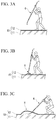
- Figs. 3A to 3C are schematic diagrams showing the lining material peeling method of the present embodiment.
- a method for peeling a polyurea material 12 from a concrete structure 10 will be described.
- the concrete structure 10 has a structure in which the polyurea material 12 as a lining material is fixedly formed on an upper surface (surface) of a concrete material 11 as a base material.
- an operator first grips the nozzle unit 6 as shown in Fig. 3A .
- the operator grips the nozzle unit 6 such that the distal end portion 62 of the nozzle unit 6 faces downward.
- the operator pushes the distal end portion 62 of the nozzle unit 6 against the polyurea material 12 and injects the liquid nitrogen X onto the surface of the polyurea material 12.
- the liquid nitrogen X is locally injected, the polyurea material 12 is locally weakened, and a penetration hole is formed in the polyurea material 12.
- the liquid nitrogen X is supplied to a boundary between the concrete material 11 and the polyurea material 12.
- the liquid nitrogen X is supplied (injected) to the boundary between the concrete material 11 and the polyurea material 12 in a liquid state.
- the liquid nitrogen X supplied to the boundary between the concrete material 11 and the polyurea material 12 evaporates and expands at the boundary. Due to an expansion force of the liquid nitrogen X when the liquid nitrogen X evaporates, the polyurea material 12 is peeled from the concrete material 11 at a circular region in plan view. That is, as shown in Fig. 3B , the distal end portion 62 of the nozzle unit 6 is made to enter below the polyurea material 12, thereby forming a circular peeling region H in plan view.
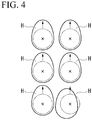
- Fig. 4 is a plan view schematically showing the peeling region H.
- each peeling region H has a circular shape as shown by a two-dot dashed line when the distal end portion 62 of the nozzle unit 6 penetrates the polyurea material 12 as shown in Fig. 3B , and then, by operating the nozzle unit 6 as shown in Fig. 3C , the peeling region H spreads forward.
- the peeling regions H each having such a shape adjacently as shown in Fig. 4 , the entire polyurea material 12 is peeled from the concrete material 11.
- the polyurea material 12 is peeled from the concrete material 11 by the expansion force when the liquid nitrogen X evaporates.
- the expansion rate when the liquid nitrogen X evaporates is about 700 times. For this reason, by utilizing the expansion force of the liquid nitrogen X, the polyurea material 12 can be peeled from the concrete material 11 without heating.
- liquid nitrogen X is injected onto the surface of the polyurea material 12 to form a penetration hole in the polyurea material 12, and the liquid nitrogen X is injected from the penetration hole to the boundary between the concrete material 11 and the polyurea material 12. Therefore, the liquid nitrogen X can be easily injected to the boundary between the concrete material 11 and the polyurea material 12 without using another device for forming a penetration hole in the polyurea material 12.
- the injection opening of the nozzle unit 6 is directed forward by tilting the tubular portion 6b with respect to the surface of the polyurea material 12 and by rotating the tubular portion 6b around the axis L (see Fig. 2 ) of the base portion 61. For this reason, the peeling region H can be easily enlarged by a simple operation.
- the tubular portion 6b of the nozzle unit 6 includes the distal end portion 62 that is curved and connected to the base portion 61, and the distal end portion 62 has the injection opening 6d1. Therefore, for example, by rotating the base portion 61 about the axis L, the injection opening 6d1 can be easily moved in the circumferential direction when viewed from the base portion 61 side.
- the tubular portion 6b of the nozzle unit 6 has the base portion 61 set to have a straight tubular shape, and the distal end portion 62 which injects the liquid nitrogen X in a direction inclined with respect to the axis L of the base portion 61. For this reason, by rotating the straight tubular base portion 61 about the axis L, the injection direction of the liquid nitrogen X can be easily changed to the circumferential direction, and the injection direction of the liquid nitrogen X can be changed with the minimum necessary operation.
- the injection opening 6d1 of the distal end portion 62 of the nozzle unit 6 opens toward the side opposite to the base portion 61.
- the peeling region H can be expanded toward the front of the nozzle unit 6, it is suitable for peeling or the like of the polyurea material 12.
- the configuration in which the polyurea material 12 is peeled from the concrete material 11 using the nozzle unit 6 having the distal end portion 62 that is curved and connected to the base portion 61 has been described.
- the polyurea material 12 is peeled using a straight tubular nozzle unit 6S.
- the operator grips the nozzle unit 6S.
- the operator grips the nozzle unit 6S so that the distal end portion 62 of the nozzle unit 6S faces downward.
- the operator pushes the distal end portion 62 of the nozzle unit 6 against the polyurea material 12 and injects the liquid nitrogen X onto the surface of the polyurea material 12.
- the polyurea material 12 locally weakens by local injection of liquid nitrogen X, and a penetration hole is formed in polyurea material 12.
- the liquid nitrogen X is supplied to the boundary between the concrete material 11 and the polyurea material 12.
- the liquid nitrogen X is supplied (injected) to the boundary between the concrete material 11 and the polyurea material 12 in a liquid state. Due to the expansion force of the liquid nitrogen X when the liquid nitrogen X evaporates, the peeling region H having a circular shape in plan view is formed.
- Fig. 6 is a plan view schematically showing the peeling region H.
- each peeling region H has a circular shape as the distal end portion 62 of the nozzle unit 6 penetrates the polyurea material 12 as shown in Fig. 3B .
- the peeling regions H adjacently as shown in Fig. 6 in this way, the entire polyurea material 12 is peeled from the concrete material 11.
- the polyurea material 12 is peeled from the concrete material 11 by the expansion force when the liquid nitrogen X evaporates. For this reason, the polyurea material 12 can be peeled from the concrete material 11 without heating, by utilizing the expansion force of the liquid nitrogen X.
- Fig. 7 is an enlarged perspective view showing a schematic configuration of the nozzle unit 6A. As shown in Fig. 7 , the nozzle unit 6A is equipped with gripping portions 6e in addition to the configuration of the nozzle unit 6 of the first embodiment.
- the gripping portion 6e is attached to the tubular portion 6b and protrudes from the tubular portion 6b to a radially outer side of the tubular portion 6b. As shown in Fig. 7 , the gripping portion 6e is attached to the base portion 61 (linear part) of the tubular portion 6b. A plurality (two in the present embodiment) of gripping portions 6e are provided apart from each other in an extending direction of the base portion 61 (an extending direction of the flow path R in the base portion 61).
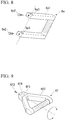
- Fig. 8 is an enlarged perspective view showing a schematic configuration of the gripping portion 6e.
- the gripping portion 6e includes a main body portion 6e1 and lock portions 6e2.
- the main body portion 6e1 is a substantially C-shaped part, and penetration holes 6e3 are formed at both end portions of the main body portion 6e1 to be concentric with each other.
- a diameter of the penetration hole 6e3 is slightly larger than an outer diameter of the base portion 61 of the tubular portion 6b, and the base portion 61 is inserted through the penetration holes 6e3.
- a screw hole into which the lock portion 6e2 is screwed is formed at each end portion of the main body portion 6e1.
- Each of the screw holes is connected to the respective penetration hole 6e3 from the radially outer side of the penetration hole 6e3.
- the distal end portion of the lock portion 6e2 screwed into the screw hole can be brought into contact with the tubular portion 6b inserted through the penetration holes 6e3.
- the lock portion 6e2 is a screw part screwed into the aforementioned screw hole provided in the main body portion 6e1, and is moved in a direction along an axis thereof (a radial direction of the base portion 61 of the tubular portion 6b) by being rotated about the axis.
- a tightening direction a direction in which the lock portion 6e2 moves to the radially inner side of the base portion 61 of the tubular portion 6b
- the distal end portion of the lock portion 6e2 comes into contact with the base portion 61 of the tubular portion 6b to regulate the movement of the main body portion 6e1 with respect to the base portion 61 by the frictional force.
- the gripping portion 6e is movable along the extending direction (the longitudinal direction) of the base portion 61 of the tubular portion 6b by loosening the lock portion 6e2. Further, the gripping portion 6e is fixed to the tubular portion 6b by tightening the lock portion 6e2.
- the gripping portion 6e disposed on the distal end side of the tubular portion 6b and the gripping portion 6e disposed on the connecting portion 6a side can be fix to protrude in different directions about the tubular portion 6b. Accordingly, for example, the gripping portion 6e disposed on the distal end side of the tubular portion 6b can be made to protrude to a left hand side of the operator, and the gripping portion 6e disposed on the connecting portion 6a side can be made to protrude to a right hand side of the operator.
- the nozzle unit 6A is equipped with the gripping portion 6e attached to the tubular portion 6b and protruding radially outward from the tubular portion 6b. For this reason, the operator can operate the nozzle unit 6A by gripping the gripping portion 6e, and the operability of the nozzle unit 6A can be improved.
- the plurality of gripping portions 6e are provided apart from each other in the extending direction of the flow path R on the base portion 61 of the tubular portion 6b. For this reason, the operator can stably hold the nozzle unit 6A with both hands, and workability can be improved.
- the two gripping portions 6e protrude in different directions around the tubular portion 6b. For this reason, for example, the operator can grip the nozzle unit 6A with both left and right hands from both sides, and the workability can be further improved.
- the gripping portion 6e is attached to be movable in the extending direction of the tubular portion 6b. For this reason, the position of the gripping portion 6e can be adjusted depending on the working position and the physique of the operator, and the workability can be further improved.
- the main body portion 6f2 may include a rotatable gripping portion 6f instead of the gripping portion 6e.
- the gripping portion 6f shown in Figs. 9 and 10 includes a support portion 6f1, a main body portion 6f2, and a lock portion 6f3.
- the support portion 6f1 has a penetration hole 6f4 having a diameter slightly larger than the outer diameter of the base portion 61 of the tubular portion 6b, and the base portion 61 is inserted through the penetration hole 6f4.
- the support portion 6f1 rotatably supports the main body portion 6f2, as shown in Figs. 9 and 10 .
- the support portion 6f1 has a screw hole into which the lock portion 6f3 is screwed.
- the screw hole is connected to the penetration hole 6f4 from the radially outer side of the penetration hole 6f4. As a result, the distal end portion of the lock portion 6f3 screwed into the screw hole can be brought into contact with the tubular portion 6b inserted into the penetration hole 6f4.
- the main body portion 6f2 is a substantially triangular annular part, and one of the apexes thereof is rotatably connected to the support portion 6f1.
- the main body portion 6f2 is rotatable about a rotation axis orthogonal to the axis L (see Fig. 2 ) of the base portion 61 of the tubular portion 6b.
- the lock portion 6f3 is a screw portion screwed into the above-described screw hole provided in the support portion 6f1, and is moved in a direction along an axis thereof (the radial direction of the base portion 61 of the tubular portion 6b) by being rotated about the axis.
- a tightening direction a direction in which the lock portion 6f3 moves to the radially inner side of the base portion 61 of the tubular portion 6b
- the distal end portion of the lock portion 6f3 comes into contact with the base portion 61 of the tubular portion 6b to regulate the movement of the main body portion 6f2 with respect to the base portion 61 by the frictional force.
- the gripping portion 6f is movable along the extending direction (the longitudinal direction) of the base portion 61 of the tubular portion 6b by loosening the lock portion 6f3. Further, the gripping portion 6f is fixed to the tubular portion 6b by tightening the lock portion 6f3.
- the operator can arbitrarily adjust a rotation angle of the main body portion 6f2 with respect to the support portion 6f1, and the operatability is improved.
- a gripping portion 6g equipped with a rod-shaped main body portion 6g1 and a lock portion 6g2 may be provided, instead of the gripping portion 6e.
- a concentric penetration hole 6g3 is formed at one end portion of the main body portion 6g1.
- a diameter of the penetration hole 6g3 is slightly larger than the outer diameter of the base portion 61 of the tubular portion 6b, and the base portion 61 is inserted through the penetration hole 6g3.
- a screw hole into which the lock portion 6g2 is screwed is formed at the end portion of the main body portion 6gl. The screw hole is connected to the penetration hole 6g3 from the radially outer side of the penetration hole 6g3. Therefore, the distal end portion of the lock portion 6g2 screwed into the screw hole can be brought into contact with the tubular portion 6b inserted into the penetration hole 6g3.
- the lock portion 6g2 is a screw portion screwed into the above-described screw hole provided in the main body portion 6g1, and is moved in a direction along an axis thereof (the radial direction of the base portion 61 of the tubular portion 6b) by being rotated about the axis.
- a tightening direction a direction in which the lock portion 6g2 moves to the radially inner side of the base portion 61 of the tubular portion 6b
- the distal end portion of the lock portion 6g2 comes into contact with the base portion 61 of the tubular portion 6b to regulate the movement of the main body portion 6g1 with respect to the base portion 61 by the frictional force.
- the gripping portion 6g is movable along the extending direction (the longitudinal direction) of the base portion 61 of the tubular portion 6b by loosening the lock portion 6g2. Further, the gripping portion 6g is fixed to the tubular portion 6b by tightening the lock portion 6g2.
- Fig. 12 is an enlarged perspective view showing a schematic configuration of a nozzle unit 6B.
- the nozzle unit 6B is equipped with a heat insulating portion 6h, in addition to the configuration of the nozzle unit 6 of the aforementioned first embodiment.
- the heat insulating portion 6h is fixed to the tubular portion 6b to cover the periphery of the base portion 61 of the tubular portion 6b. That is, the nozzle unit 6B has the heat insulating portion 6h which is fixed to the tubular portion 6b and covers the flow path R from the radially outer side.
- the heat insulating portion 6h prevents cold heat of the liquid nitrogen flowing through the flow path R of the tubular portion 6b from reaching the operator, and is formed of, for example, a foamed plastic material.
- Fig. 13 is a partially enlarged perspective view showing a schematic configuration of the heat insulating portion 6h provided in the nozzle unit 6B.
- the heat insulating portion 6h is constituted by a plurality of heat insulating blocks 6i arranged continuously in the extending direction of the tubular portion 6b.
- Each heat insulating block 6i has an annular shape having a central opening through which the tubular portion 6b is inserted, and has a slit 6j extending from the outer peripheral surface thereof to the central opening.
- the slit 6j is a part through which the tubular portion 6b passes when the heat insulating block 6i is attached to and detached from the tubular portion 6b.
- the slit 6j can be expanded by elastically deforming the heat insulating block 6i, and can pass through the tubular portion 6b in the expanded state.
- the nozzle unit 6B by attaching and detaching the heat insulating blocks 6i, it is possible to change a range in which the heat insulating portion 6h covers the tubular portion 6b. That is, according to the nozzle unit 6B, the heat insulating portion 6h can be divided in the extending direction of the tubular portion 6b.
- the method for peeling the polyurea material 12 from the concrete material 11 has been described.
- the present disclosure is not limited thereto, and may be applied to, for example, a method for peeling a fiber-reinforced plastic material (a lining material) from a metal pipe (a base material).
- liquid nitrogen is used as the liquefied fluid that vaporizes after injection
- present disclosure is not limited thereto.
- liquid carbon dioxide or liquid helium may be used as the liquefied fluid.
- the distal end portion 62 of the tubular portion 6b is curved and connected to the base portion 61 has been described in the aforementioned first embodiment.
- the present disclosure is not limited thereto, and the distal end portion 62 may be bent and connected to the base portion 61 in the tubular portion 6b.
- the polyurea material 12 can be peeled from the concrete material 11, the operator can easily recover the polyurea material 12 without using a recovery device or the like. For this reason, it is possible to prevent problems such as clogging of the polyurea material 12 in the recovery device or the like at the time of recovery.
- the present disclosure is not limited thereto, and the polyurea material 12 after peeling may be automatically recovered by a recovery device or the like.
- the polyurea material 12 is not heated and the polyurea material 12 in a state of being detached from the concrete material 11 is recovered, it is possible to reduce the possibility of clogging of the polyurea material 12 in the recovery device or the like, as compared with a case in which the polyurea material 12 is mechanically cut together with the concrete material 11 and removed.
- the lining material in the lining material peeling method, can be peeled from the base material without heating.
Landscapes
- Engineering & Computer Science (AREA)
- Mechanical Engineering (AREA)
- Environmental & Geological Engineering (AREA)
- Manufacturing & Machinery (AREA)
- Working Measures On Existing Buildindgs (AREA)
- Separation, Recovery Or Treatment Of Waste Materials Containing Plastics (AREA)
Abstract
Description
- The present disclosure relates to a lining material peeling method.
- Priority is claimed on Japanese Patent Application No.
2018-006623, filed January 18, 2018 - For example, in some cases, a lining material may be fixedly formed on a base material made of a concrete material or a metal material to impart waterproofness or the like to a structure. Such a lining material is formed by, for example, injecting a plastic material before curing to the base material and then curing the injected plastic material.
- For example, Patent Document 1 discloses a lining peeling device for peeling the aforementioned lining material from the base material. The lining peeling device is equipped with a coil which heats the lining material, and a scraper which is inserted between the base material and the lining material which is in a state of being easily peeled off by heating.
- [Patent Document 1] Japanese Unexamined Patent Application, First Publication No.
2008-272995 - However, when a hardly peelable lining material such as polyurea is firmly fixed to the base material, peeling is not facilitated by heating. For this reason, a hardly peelable lining material such as polyurea cannot be peeled from the base material by the lining peeling device disclosed in Patent Document 1. Therefore, there is demand for a method capable of peeling a hardly peelable lining material from the base material without heating.
- The present disclosure has been made in view of the above-described problems, and an object thereof is to enable a lining material to be peeled from a base material without heating, in a lining material peeling method.
- According to an aspect of the present disclosure, there is provided a lining material peeling method of peeling a lining material, which is fixedly formed on a surface of a base material, from the base material, in which a liquefied fluid which evaporates after injection is injected to a boundary between the base material and the lining material.
- In the lining material peeling method according to the aspect, the liquefied fluid may be injected onto a surface of the lining material to form a penetration hole in the lining material, and the liquefied fluid may be injected from the penetration hole to the boundary between the base material and the lining material.
- In the lining material peeling method according to the aspect, the liquefied fluid may be injected by a nozzle unit including a tubular body in which a flow path configured to guide the liquefied fluid is formed and which has an injection opening formed at a distal end portion thereof.
- In the lining material peeling method according to the aspect, the distal end portion of the tubular portion may be bent or curved and connected to a base portion, and the flow path may be formed in a part including the distal end portion and the base portion.
- In the lining material peeling method according to the aspect, in a state in which the distal end portion penetrates the lining material, the liquefied fluid may be injected to the boundary between the base material and the lining material by tilting the tubular portion with respect to the surface of the lining material and by rotating the tubular portion about an axis of the base portion.
- In the lining material peeling method according to the aspect, the base material may be a concrete material, and the lining material may be a polyurea material.
- In the lining material peeling method according to the aspect, the base material may be a metal pipe, and the lining material may be a fiber-reinforced plastic material.
- In the lining material peeling method according to the aspect, the liquefied fluid may be liquid nitrogen.
- According to the present disclosure, the lining material is peeled from the base material by an expansion force when the liquefied fluid evaporates. An expansion ratio when the liquid evaporates is, for example, several hundred times or more. For this reason, by utilizing the expansion force of the liquefied fluid, the lining material can be peeled from the base material without heating. Therefore, according to the present disclosure, in the lining material peeling method, the lining material can be peeled from the base material without heating.
-
-
Fig. 1 is a schematic diagram showing a schematic configuration of a liquid nitrogen injection system used in a lining material peeling method according to a first embodiment of the present disclosure. -
Fig. 2 is an enlarged perspective view showing a schematic configuration of a nozzle unit provided in the liquid nitrogen injection system used in the lining material peeling method according to the first embodiment of the present disclosure. -
Fig. 3A is a schematic diagram showing the operation of the lining material peeling method according to the first embodiment of the present disclosure. -
Fig. 3B is a schematic diagram showing the operation of the lining material peeling method according to the first embodiment of the present disclosure. -
Fig. 3C is a schematic diagram showing the operation of the lining material peeling method according to the first embodiment of the present disclosure. -
Fig. 4 is a schematic diagram showing the operation of the lining material peeling method according to the first embodiment of the present disclosure. -
Fig. 5A is a schematic diagram showing the operation of a lining material peeling method according to a second embodiment of the present disclosure. -
Fig. 5B is a schematic diagram showing the operation of the lining material peeling method according to the second embodiment of the present disclosure. -
Fig. 6 is a schematic diagram showing the operation of the lining material peeling method according to the second embodiment of the present disclosure. -
Fig. 7 is an enlarged perspective view showing a schematic configuration of a first modified example of the nozzle unit. -
Fig. 8 is an enlarged perspective view showing a schematic configuration of a gripping portion provided in the first modified example of the nozzle unit. -
Fig. 9 is an enlarged perspective view showing a schematic configuration of a modified example of the gripping portion provided in the first modified example of the nozzle unit. -
Fig. 10 is an enlarged perspective view showing a schematic configuration of a modified example of the gripping portion provided in the first modified example of the nozzle unit. -
Fig. 11 is an enlarged perspective view showing a schematic configuration of a modified example of the gripping portion provided in the first modified example of the nozzle unit. -
Fig. 12 is an enlarged perspective view showing a schematic configuration of a second modified example of the nozzle unit. -
Fig. 13 is a partially enlarged perspective view showing a schematic configuration of a heat insulating portion provided in the second modified example of the nozzle unit. - Hereinafter, an embodiment of a lining material peeling method according to the present disclosure will be described with reference to the drawings.
-
Fig. 1 is a schematic diagram showing a schematic configuration of a liquid nitrogen injection system 1 used in a lining material peeling method of the present embodiment. As shown inFig. 1 , the liquid nitrogen injection system 1 is equipped with astorage tank 2, a liquid nitrogen boosting device 3, achiller 4, aflexible hose 5, and anozzle unit 6. - The
storage tank 2 is a pressure tank which stores a liquid nitrogen X, and is connected to the liquid nitrogen boosting device 3 and thechiller 4. The liquid nitrogen injection system 1 may be configured to receive the supply of the liquid nitrogen X from outside, without including thestorage tank 2. - The liquid nitrogen boosting device 3 boosts the liquid nitrogen X, which is supplied from the
storage tank 2, to a predetermined injection pressure. For example, the liquid nitrogen boosting device 3 is equipped with a boost pump for pumping the liquid nitrogen X, a pre-pump for primarily boosting the liquid nitrogen X sent from the boost pump, an intensifier pump for secondarily boosting the primarily-boosted liquid nitrogen X up to the injection pressure, and the like. The liquid nitrogen boosting device 3 is connected to thechiller 4. - The
chiller 4 is a heat exchanger which cools the boosted liquid nitrogen X to an injection temperature, by performing a heat exchange between the liquid nitrogen X heated by being boosted with the liquid nitrogen boosting device 3 and the liquid nitrogen X supplied from thestorage tank 2. One end of theflexible hose 5 is connected to thechiller 4. - For example, the liquid nitrogen boosting device 3 and the
chiller 4 are unitized and disposed on a single mobile carrier. Since the liquid nitrogen boosting device 3 and thechiller 4 which are unitized, and thestorage tank 2 as necessary are disposed in the mobile carrier, the liquid nitrogen injection system 1 can be easily moved. The liquid nitrogen boosting device 3 and thechiller 4 do not necessarily need to be unitized. For example, the liquid nitrogen boosting device 3 and thechiller 4 may be disposed separately, and thechiller 4 may be disposed near thenozzle unit 6. Accordingly, it is possible to suppress the temperature of the liquid nitrogen X, which has been cooled by thechiller 4, from rising before the liquid nitrogen X reaches thenozzle unit 6 and to enhance a jet force of the liquid nitrogen X injected from thenozzle unit 6. - The
flexible hose 5 is a hose with flexibility having one end connected to thechiller 4 and the other end connected to thenozzle unit 6. Theflexible hose 5 guides the boosted liquid nitrogen X from thechiller 4 to thenozzle unit 6. Theflexible hose 5 has pressure resistance and heat insulation, and guides the liquid nitrogen X, which is supplied from thechiller 4, to thenozzle unit 6, while suppressing a decrease in pressure and temperature to a minimum. -
Fig. 2 is an enlarged perspective view showing a schematic configuration of thenozzle unit 6. As shown inFig. 2 , thenozzle unit 6 is equipped with a connectingportion 6a and atubular portion 6b. Theflexible hose 5 is connected to the connectingportion 6a. A flow path (not shown) is formed inside the connectingportion 6a. - The
tubular portion 6b includes acylindrical trunk portion 6c having a flow path R formed therein, and anorifice portion 6d fixed to the distal end portion of thetrunk portion 6c. Thetrunk portion 6c is, for example, a long pipe-shaped part that is heat-insulated, and guides the liquid nitrogen X from the connectingportion 6a to theorifice portion 6d through the flow path R formed therein along a longitudinal direction thereof. Thetrunk portion 6c is gripped by an operator when injecting the liquid nitrogen X onto the object. Theorifice portion 6d is fixed to the distal end of thetrunk portion 6c, and has an injection opening 6d1 for injecting the liquid nitrogen X forward. The injection opening 6dl is connected to the flow path R of thetrunk portion 6c, and the liquid nitrogen X flowing through the flow path R is injected from the injection opening 6d1 to the outside of thetubular portion 6b. - The
tubular portion 6b has a straighttubular base portion 61 and adistal end portion 62 including theorifice portion 6d. Thebase portion 61 is a part on a root side (the connectingportion 6a side) of thetrunk portion 6c, and extends linearly along a linear axis L. Thedistal end portion 62 includes the injection opening 6d1 by having theorifice portion 6d, and injects the liquid nitrogen X. As shown inFig. 2 , thedistal end portion 62 is curved and connected to thebase portion 61 such that the injection opening 6d1 is opened toward an opposite side of thebase portion 61, and an injection direction of the liquid nitrogen X inclines with respect to the axis L of thebase portion 61. More specifically, a part of thedistal end portion 62 on thebase portion 61 side is curved with a constant radius of curvature, a part of thedistal end portion 62 on the injection opening 6d1 side has a linear shape, and the part of thedistal end portion 62 on thebase portion 61 side and the part on the injection opening 6dl side are integrally connected so that an axis L1 of thedistal end portion 62 on the injection opening 6d1 side forms an angle α smaller than 90° (about 45° in the present embodiment) with respect to the axis L of thebase portion 61. - The
nozzle unit 6 has thetubular portion 6b in which thedistal end portion 62 having the injection opening 6d1 is curved and connected to thebase portion 61 and which has the flow path R which guides the liquid nitrogen X to thebase portion 61 and thedistal end portion 62. Further, thetubular portion 6b has thebase portion 61 set to have a straight tube shape, and thedistal end portion 62 which injects the liquid nitrogen X in a direction inclined with respect to the axis L of thebase portion 61. - In the liquid nitrogen injection system 1 including the
nozzle unit 6, the liquid nitrogen X is supplied from thestorage tank 2 to the liquid nitrogen boosting device 3. The liquid nitrogen X is boosted to the injection pressure by the liquid nitrogen boosting device 3 and then is supplied to thechiller 4. The liquid nitrogen X supplied from the liquid nitrogen boosting device 3 to thechiller 4 is cooled by exchanging heat with the liquid nitrogen X supplied from thestorage tank 2 to thechiller 4 through another route. The liquid nitrogen X cooled by thechiller 4 is supplied to thenozzle unit 6 via theflexible hose 5. The liquid nitrogen X supplied to thenozzle unit 6 flows through the flow path R inside thetubular portion 6b, and is injected toward the outside from the injection opening 6d1. -
Figs. 3A to 3C are schematic diagrams showing the lining material peeling method of the present embodiment. In the present embodiment, a method for peeling apolyurea material 12 from aconcrete structure 10 will be described. - The
concrete structure 10 has a structure in which thepolyurea material 12 as a lining material is fixedly formed on an upper surface (surface) of aconcrete material 11 as a base material. When thepolyurea material 12 is peeled from theconcrete material 11 in theconcrete structure 10, an operator first grips thenozzle unit 6 as shown inFig. 3A . Here, the operator grips thenozzle unit 6 such that thedistal end portion 62 of thenozzle unit 6 faces downward. - Subsequently, the operator pushes the
distal end portion 62 of thenozzle unit 6 against thepolyurea material 12 and injects the liquid nitrogen X onto the surface of thepolyurea material 12. When the liquid nitrogen X is locally injected, thepolyurea material 12 is locally weakened, and a penetration hole is formed in thepolyurea material 12. - Further, as shown in
Fig. 3B , when thedistal end portion 62 of thenozzle unit 6 enters below thepolyurea material 12, the liquid nitrogen X is supplied to a boundary between theconcrete material 11 and thepolyurea material 12. The liquid nitrogen X is supplied (injected) to the boundary between theconcrete material 11 and thepolyurea material 12 in a liquid state. The liquid nitrogen X supplied to the boundary between theconcrete material 11 and thepolyurea material 12 evaporates and expands at the boundary. Due to an expansion force of the liquid nitrogen X when the liquid nitrogen X evaporates, thepolyurea material 12 is peeled from theconcrete material 11 at a circular region in plan view. That is, as shown inFig. 3B , thedistal end portion 62 of thenozzle unit 6 is made to enter below thepolyurea material 12, thereby forming a circular peeling region H in plan view. - Subsequently, as shown in
Fig. 3C , as the operator tilts thetubular portion 6b with respect to the surface of thepolyurea material 12 and rotates thetubular portion 6b around the axis L (seeFig. 2 ) of thebase portion 61 in a state in which thedistal end portion 62 of thenozzle unit 6 penetrates thepolyurea material 12, the injection opening of thenozzle unit 6 is directed forward. In this state, the liquid nitrogen X is injected to the boundary between theconcrete material 11 and thepolyurea material 12. As a result, at the boundary between theconcrete material 11 and thepolyurea material 12, the liquid nitrogen X is injected forward as viewed from the operator, and the peeling region H spreads forward. By operating thenozzle unit 6 in this manner, the peeling region H can be easily enlarged. -
Fig. 4 is a plan view schematically showing the peeling region H. As shown inFig. 4 , each peeling region H has a circular shape as shown by a two-dot dashed line when thedistal end portion 62 of thenozzle unit 6 penetrates thepolyurea material 12 as shown inFig. 3B , and then, by operating thenozzle unit 6 as shown inFig. 3C , the peeling region H spreads forward. By forming the peeling regions H each having such a shape adjacently as shown inFig. 4 , theentire polyurea material 12 is peeled from theconcrete material 11. - According to the lining material peeling method of the present embodiment, the
polyurea material 12 is peeled from theconcrete material 11 by the expansion force when the liquid nitrogen X evaporates. The expansion rate when the liquid nitrogen X evaporates is about 700 times. For this reason, by utilizing the expansion force of the liquid nitrogen X, thepolyurea material 12 can be peeled from theconcrete material 11 without heating. - Further, in the lining material peeling method of the present embodiment, liquid nitrogen X is injected onto the surface of the
polyurea material 12 to form a penetration hole in thepolyurea material 12, and the liquid nitrogen X is injected from the penetration hole to the boundary between theconcrete material 11 and thepolyurea material 12. Therefore, the liquid nitrogen X can be easily injected to the boundary between theconcrete material 11 and thepolyurea material 12 without using another device for forming a penetration hole in thepolyurea material 12. - Further, in the lining material peeling method of the present embodiment, in a state in which the
distal end portion 62 of thenozzle unit 6 penetrates thepolyurea material 12, the injection opening of thenozzle unit 6 is directed forward by tilting thetubular portion 6b with respect to the surface of thepolyurea material 12 and by rotating thetubular portion 6b around the axis L (seeFig. 2 ) of thebase portion 61. For this reason, the peeling region H can be easily enlarged by a simple operation. - Further, in the lining material peeling method of the present embodiment, the
tubular portion 6b of thenozzle unit 6 includes thedistal end portion 62 that is curved and connected to thebase portion 61, and thedistal end portion 62 has the injection opening 6d1. Therefore, for example, by rotating thebase portion 61 about the axis L, the injection opening 6d1 can be easily moved in the circumferential direction when viewed from thebase portion 61 side. - Further, in the lining material peeling method of the present embodiment, the
tubular portion 6b of thenozzle unit 6 has thebase portion 61 set to have a straight tubular shape, and thedistal end portion 62 which injects the liquid nitrogen X in a direction inclined with respect to the axis L of thebase portion 61. For this reason, by rotating the straighttubular base portion 61 about the axis L, the injection direction of the liquid nitrogen X can be easily changed to the circumferential direction, and the injection direction of the liquid nitrogen X can be changed with the minimum necessary operation. - In addition, in the lining material peeling method of the present embodiment, the injection opening 6d1 of the
distal end portion 62 of thenozzle unit 6 opens toward the side opposite to thebase portion 61. For example, it is also possible to tilt the injection opening 6dl with respect to the axis L and direct the injection opening 6dl toward thebase portion 61 side. However, by directing the injection opening 6d1 toward the side opposite to thebase portion 61, since the peeling region H can be expanded toward the front of thenozzle unit 6, it is suitable for peeling or the like of thepolyurea material 12. - Next, a second embodiment of the present disclosure will be described. In the second embodiment, the explanation of parts the same as those in the first embodiment will be omitted or simplified.
- In the aforementioned first embodiment, the configuration in which the
polyurea material 12 is peeled from theconcrete material 11 using thenozzle unit 6 having thedistal end portion 62 that is curved and connected to thebase portion 61 has been described. In contrast, in the lining material peeling method of the present embodiment, as shown inFigs. 5A and 5B , thepolyurea material 12 is peeled using a straighttubular nozzle unit 6S. - In this case, first, as shown in
Fig. 5A , the operator grips thenozzle unit 6S. Here, the operator grips thenozzle unit 6S so that thedistal end portion 62 of thenozzle unit 6S faces downward. - Subsequently, the operator pushes the
distal end portion 62 of thenozzle unit 6 against thepolyurea material 12 and injects the liquid nitrogen X onto the surface of thepolyurea material 12. Thepolyurea material 12 locally weakens by local injection of liquid nitrogen X, and a penetration hole is formed inpolyurea material 12. - Further, as shown in
Fig. 5B , when thedistal end portion 62 of thenozzle unit 6 enters below thepolyurea material 12, the liquid nitrogen X is supplied to the boundary between theconcrete material 11 and thepolyurea material 12. The liquid nitrogen X is supplied (injected) to the boundary between theconcrete material 11 and thepolyurea material 12 in a liquid state. Due to the expansion force of the liquid nitrogen X when the liquid nitrogen X evaporates, the peeling region H having a circular shape in plan view is formed. -
Fig. 6 is a plan view schematically showing the peeling region H. As shown inFig. 6 , each peeling region H has a circular shape as thedistal end portion 62 of thenozzle unit 6 penetrates thepolyurea material 12 as shown inFig. 3B . By forming the peeling regions H adjacently as shown inFig. 6 in this way, theentire polyurea material 12 is peeled from theconcrete material 11. - Also in the lining material peeling method of the present embodiment, the
polyurea material 12 is peeled from theconcrete material 11 by the expansion force when the liquid nitrogen X evaporates. For this reason, thepolyurea material 12 can be peeled from theconcrete material 11 without heating, by utilizing the expansion force of the liquid nitrogen X. - Next, a first modified example of the nozzle unit will be described. In the first modified example, the explanation of the same parts as those in the first embodiment of the present disclosure will be omitted or simplified.
-
Fig. 7 is an enlarged perspective view showing a schematic configuration of thenozzle unit 6A. As shown inFig. 7 , thenozzle unit 6A is equipped withgripping portions 6e in addition to the configuration of thenozzle unit 6 of the first embodiment. - The gripping
portion 6e is attached to thetubular portion 6b and protrudes from thetubular portion 6b to a radially outer side of thetubular portion 6b. As shown inFig. 7 , the grippingportion 6e is attached to the base portion 61 (linear part) of thetubular portion 6b. A plurality (two in the present embodiment) of grippingportions 6e are provided apart from each other in an extending direction of the base portion 61 (an extending direction of the flow path R in the base portion 61). -
Fig. 8 is an enlarged perspective view showing a schematic configuration of the grippingportion 6e. As shown inFig. 8 , the grippingportion 6e includes a main body portion 6e1 and lock portions 6e2. As shown inFig. 8 , the main body portion 6e1 is a substantially C-shaped part, and penetration holes 6e3 are formed at both end portions of the main body portion 6e1 to be concentric with each other. A diameter of the penetration hole 6e3 is slightly larger than an outer diameter of thebase portion 61 of thetubular portion 6b, and thebase portion 61 is inserted through the penetration holes 6e3. Further, a screw hole into which the lock portion 6e2 is screwed is formed at each end portion of the main body portion 6e1. Each of the screw holes is connected to the respective penetration hole 6e3 from the radially outer side of the penetration hole 6e3. Thus, the distal end portion of the lock portion 6e2 screwed into the screw hole can be brought into contact with thetubular portion 6b inserted through the penetration holes 6e3. - The lock portion 6e2 is a screw part screwed into the aforementioned screw hole provided in the main body portion 6e1, and is moved in a direction along an axis thereof (a radial direction of the
base portion 61 of thetubular portion 6b) by being rotated about the axis. As the lock portion 6e2 is rotated in a tightening direction (a direction in which the lock portion 6e2 moves to the radially inner side of thebase portion 61 of thetubular portion 6b), the distal end portion of the lock portion 6e2 comes into contact with thebase portion 61 of thetubular portion 6b to regulate the movement of the main body portion 6e1 with respect to thebase portion 61 by the frictional force. - The gripping
portion 6e is movable along the extending direction (the longitudinal direction) of thebase portion 61 of thetubular portion 6b by loosening the lock portion 6e2. Further, the grippingportion 6e is fixed to thetubular portion 6b by tightening the lock portion 6e2. - Further, as shown in
Fig. 7 , it is preferable to fix thegripping portion 6e disposed on the distal end side of thetubular portion 6b and the grippingportion 6e disposed on the connectingportion 6a side to protrude in different directions about thetubular portion 6b. Accordingly, for example, the grippingportion 6e disposed on the distal end side of thetubular portion 6b can be made to protrude to a left hand side of the operator, and the grippingportion 6e disposed on the connectingportion 6a side can be made to protrude to a right hand side of the operator. - The
nozzle unit 6A is equipped with the grippingportion 6e attached to thetubular portion 6b and protruding radially outward from thetubular portion 6b. For this reason, the operator can operate thenozzle unit 6A by gripping the grippingportion 6e, and the operability of thenozzle unit 6A can be improved. - In addition, in the
nozzle unit 6A, the plurality ofgripping portions 6e are provided apart from each other in the extending direction of the flow path R on thebase portion 61 of thetubular portion 6b. For this reason, the operator can stably hold thenozzle unit 6A with both hands, and workability can be improved. - In addition, in the
nozzle unit 6A, the twogripping portions 6e protrude in different directions around thetubular portion 6b. For this reason, for example, the operator can grip thenozzle unit 6A with both left and right hands from both sides, and the workability can be further improved. - Further, in the
nozzle unit 6A, the grippingportion 6e is attached to be movable in the extending direction of thetubular portion 6b. For this reason, the position of the grippingportion 6e can be adjusted depending on the working position and the physique of the operator, and the workability can be further improved. - Further, as shown in
Figs. 9 and10 , the main body portion 6f2 may include a rotatablegripping portion 6f instead of the grippingportion 6e. The grippingportion 6f shown inFigs. 9 and10 includes a support portion 6f1, a main body portion 6f2, and a lock portion 6f3. - The support portion 6f1 has a penetration hole 6f4 having a diameter slightly larger than the outer diameter of the
base portion 61 of thetubular portion 6b, and thebase portion 61 is inserted through the penetration hole 6f4. The support portion 6f1 rotatably supports the main body portion 6f2, as shown inFigs. 9 and10 . Further, the support portion 6f1 has a screw hole into which the lock portion 6f3 is screwed. The screw hole is connected to the penetration hole 6f4 from the radially outer side of the penetration hole 6f4. As a result, the distal end portion of the lock portion 6f3 screwed into the screw hole can be brought into contact with thetubular portion 6b inserted into the penetration hole 6f4. - The main body portion 6f2 is a substantially triangular annular part, and one of the apexes thereof is rotatably connected to the support portion 6f1. The main body portion 6f2 is rotatable about a rotation axis orthogonal to the axis L (see
Fig. 2 ) of thebase portion 61 of thetubular portion 6b. - The lock portion 6f3 is a screw portion screwed into the above-described screw hole provided in the support portion 6f1, and is moved in a direction along an axis thereof (the radial direction of the
base portion 61 of thetubular portion 6b) by being rotated about the axis. As the lock portion 6f3 is rotated in a tightening direction (a direction in which the lock portion 6f3 moves to the radially inner side of thebase portion 61 of thetubular portion 6b), the distal end portion of the lock portion 6f3 comes into contact with thebase portion 61 of thetubular portion 6b to regulate the movement of the main body portion 6f2 with respect to thebase portion 61 by the frictional force. - The gripping
portion 6f is movable along the extending direction (the longitudinal direction) of thebase portion 61 of thetubular portion 6b by loosening the lock portion 6f3. Further, the grippingportion 6f is fixed to thetubular portion 6b by tightening the lock portion 6f3. - According to the gripping
portion 6f, since the main body portion 6f2 is rotatable with respect to the support portion 6f1, the operator can arbitrarily adjust a rotation angle of the main body portion 6f2 with respect to the support portion 6f1, and the operatability is improved. - Furthermore, as shown in
Fig. 11 , a grippingportion 6g equipped with a rod-shaped main body portion 6g1 and a lock portion 6g2 may be provided, instead of the grippingportion 6e. A concentric penetration hole 6g3 is formed at one end portion of the main body portion 6g1. A diameter of the penetration hole 6g3 is slightly larger than the outer diameter of thebase portion 61 of thetubular portion 6b, and thebase portion 61 is inserted through the penetration hole 6g3. Further, a screw hole into which the lock portion 6g2 is screwed is formed at the end portion of the main body portion 6gl. The screw hole is connected to the penetration hole 6g3 from the radially outer side of the penetration hole 6g3. Therefore, the distal end portion of the lock portion 6g2 screwed into the screw hole can be brought into contact with thetubular portion 6b inserted into the penetration hole 6g3. - The lock portion 6g2 is a screw portion screwed into the above-described screw hole provided in the main body portion 6g1, and is moved in a direction along an axis thereof (the radial direction of the
base portion 61 of thetubular portion 6b) by being rotated about the axis. As the lock portion 6g2 is rotated in a tightening direction (a direction in which the lock portion 6g2 moves to the radially inner side of thebase portion 61 of thetubular portion 6b), the distal end portion of the lock portion 6g2 comes into contact with thebase portion 61 of thetubular portion 6b to regulate the movement of the main body portion 6g1 with respect to thebase portion 61 by the frictional force. - The gripping
portion 6g is movable along the extending direction (the longitudinal direction) of thebase portion 61 of thetubular portion 6b by loosening the lock portion 6g2. Further, the grippingportion 6g is fixed to thetubular portion 6b by tightening the lock portion 6g2. - Next, a second modified example of the nozzle unit will be described. In the second modified example, explanation of the same parts as those in the first embodiment of the present disclosure will be omitted or simplified.
-
Fig. 12 is an enlarged perspective view showing a schematic configuration of anozzle unit 6B. As shown inFig. 12 , thenozzle unit 6B is equipped with aheat insulating portion 6h, in addition to the configuration of thenozzle unit 6 of the aforementioned first embodiment. - The
heat insulating portion 6h is fixed to thetubular portion 6b to cover the periphery of thebase portion 61 of thetubular portion 6b. That is, thenozzle unit 6B has theheat insulating portion 6h which is fixed to thetubular portion 6b and covers the flow path R from the radially outer side. Theheat insulating portion 6h prevents cold heat of the liquid nitrogen flowing through the flow path R of thetubular portion 6b from reaching the operator, and is formed of, for example, a foamed plastic material. -
Fig. 13 is a partially enlarged perspective view showing a schematic configuration of theheat insulating portion 6h provided in thenozzle unit 6B. As shown inFig. 13 , theheat insulating portion 6h is constituted by a plurality ofheat insulating blocks 6i arranged continuously in the extending direction of thetubular portion 6b. Eachheat insulating block 6i has an annular shape having a central opening through which thetubular portion 6b is inserted, and has a slit 6j extending from the outer peripheral surface thereof to the central opening. The slit 6j is a part through which thetubular portion 6b passes when theheat insulating block 6i is attached to and detached from thetubular portion 6b. The slit 6j can be expanded by elastically deforming theheat insulating block 6i, and can pass through thetubular portion 6b in the expanded state. - According to the
nozzle unit 6B, by attaching and detaching theheat insulating blocks 6i, it is possible to change a range in which theheat insulating portion 6h covers thetubular portion 6b. That is, according to thenozzle unit 6B, theheat insulating portion 6h can be divided in the extending direction of thetubular portion 6b. - Although the preferred embodiments of the present disclosure have been described with reference to the drawings, the present disclosure is not limited to the aforementioned embodiments. The shapes, combinations, and the like of the constituent members shown in the aforementioned embodiments are merely examples, and can be variously changed on the basis of design requirements and the like, without departing from the spirit of the present disclosure.
- For example, in the aforementioned embodiment, the method for peeling the
polyurea material 12 from theconcrete material 11 has been described. However, the present disclosure is not limited thereto, and may be applied to, for example, a method for peeling a fiber-reinforced plastic material (a lining material) from a metal pipe (a base material). - Further, the configuration in which the liquid nitrogen is used as the liquefied fluid that vaporizes after injection has been described in the aforementioned embodiment. However, the present disclosure is not limited thereto. For example, liquid carbon dioxide or liquid helium may be used as the liquefied fluid.
- Further, the configuration in which the
distal end portion 62 of thetubular portion 6b is curved and connected to thebase portion 61 has been described in the aforementioned first embodiment. However, the present disclosure is not limited thereto, and thedistal end portion 62 may be bent and connected to thebase portion 61 in thetubular portion 6b. - In addition, in the aforementioned embodiment, since the
polyurea material 12 can be peeled from theconcrete material 11, the operator can easily recover thepolyurea material 12 without using a recovery device or the like. For this reason, it is possible to prevent problems such as clogging of thepolyurea material 12 in the recovery device or the like at the time of recovery. However, the present disclosure is not limited thereto, and thepolyurea material 12 after peeling may be automatically recovered by a recovery device or the like. Even in such a case, according to the present disclosure, since thepolyurea material 12 is not heated and thepolyurea material 12 in a state of being detached from theconcrete material 11 is recovered, it is possible to reduce the possibility of clogging of thepolyurea material 12 in the recovery device or the like, as compared with a case in which thepolyurea material 12 is mechanically cut together with theconcrete material 11 and removed. - According to the present disclosure, in the lining material peeling method, the lining material can be peeled from the base material without heating.
-
- 1
- Liquid nitrogen injection system
- 2
- Storage tank
- 3
- Liquid nitrogen boosting device
- 4
- Chiller
- 5
- Flexible hose
- 6
- Nozzle unit
- 6a
- Connecting portion
- 6A
- Nozzle unit
- 6b
- Tubular portion
- 6B
- Nozzle unit
- 6c
- Trunk portion
- 6d
- Orifice portion
- 6d1
- Injection opening
- 6e
- Gripping portion
- 6e1
- Main body portion
- 6e2
- Lock portion
- 6e3
- Penetration hole
- 6f
- Gripping portion
- 6f1
- Support portion
- 6f2
- Main body portion
- 6f3
- Lock portion
- 6f4
- Penetration hole
- 6g
- Gripping portion
- 6g1
- Main body portion
- 6g2
- Lock portion
- 6g3
- Penetration hole
- 6h
- Heat insulating portion
- 6i
- Insulating block
- 6j
- Slit
- 6S
- Nozzle unit
- 10
- Concrete structure
- 11
- Concrete material (base material)
- 12
- Polyurea material (lining material)
- 61
- Base portion
- 62
- Distal end portion
- H
- Peeling region
- L
- Axis
- L1
- Axis
- R
- Flow path
- X
- Liquid nitrogen (liquefied fluid)
Claims (8)
- A lining material peeling method of peeling a lining material, which is fixedly formed on a surface of a base material, from the base material,
wherein a liquefied fluid which evaporates after injection is injected to a boundary between the base material and the lining material. - The lining material peeling method according to claim 1, wherein the liquefied fluid is injected onto a surface of the lining material to form a penetration hole in the lining material, and the liquefied fluid is injected from the penetration hole to the boundary between the base material and the lining material.
- The lining material peeling method according to claim 1 or 2, wherein the liquefied fluid is injected by a nozzle unit including a tubular body in which a flow path configured to guide the liquefied fluid is formed and which has an injection opening formed at a distal end portion thereof.
- The lining material peeling method according to claim 3, wherein the distal end portion of the tubular portion is bent or curved and connected to a base portion, and the flow path is formed in a part including the distal end portion and the base portion.
- The lining material peeling method according to claim 4, wherein, in a state in which the distal end portion penetrates the lining material, the liquefied fluid is injected to the boundary between the base material and the lining material by tilting the tubular portion with respect to the surface of the lining material and by rotating the tubular portion about an axis of the base portion.
- The lining material peeling method according to any one of claims 1 to 5, wherein the base material is a concrete material, and the lining material is a polyurea material.
- The lining material peeling method according to any one of claims 1 to 5, wherein the base material is a metal pipe, and the lining material is a fiber-reinforced plastic material.
- The lining material peeling method according to any one of claims 1 to 7, wherein the liquefied fluid is liquid nitrogen.
Applications Claiming Priority (2)
| Application Number | Priority Date | Filing Date | Title |
|---|---|---|---|
| JP2018006623 | 2018-01-18 | ||
| PCT/JP2018/040162 WO2019142435A1 (en) | 2018-01-18 | 2018-10-29 | Lining material peeling method |
Publications (3)
| Publication Number | Publication Date |
|---|---|
| EP3741535A1 true EP3741535A1 (en) | 2020-11-25 |
| EP3741535A4 EP3741535A4 (en) | 2022-02-23 |
| EP3741535B1 EP3741535B1 (en) | 2024-10-30 |
Family
ID=67302070
Family Applications (1)
| Application Number | Title | Priority Date | Filing Date |
|---|---|---|---|
| EP18900709.9A Active EP3741535B1 (en) | 2018-01-18 | 2018-10-29 | Lining material peeling method |
Country Status (8)
| Country | Link |
|---|---|
| US (1) | US11097528B2 (en) |
| EP (1) | EP3741535B1 (en) |
| JP (1) | JP6958638B2 (en) |
| KR (1) | KR102341398B1 (en) |
| CN (1) | CN111212715B (en) |
| CA (1) | CA3083246C (en) |
| TW (1) | TWI684506B (en) |
| WO (1) | WO2019142435A1 (en) |
Families Citing this family (1)
| Publication number | Priority date | Publication date | Assignee | Title |
|---|---|---|---|---|
| JP7054052B2 (en) * | 2018-04-23 | 2022-04-13 | 株式会社Ihi | Lining material peeling method |
Family Cites Families (24)
| Publication number | Priority date | Publication date | Assignee | Title |
|---|---|---|---|---|
| JPS59138605A (en) * | 1983-01-24 | 1984-08-09 | 株式会社 呉英製作所 | Removal of mark on road surface |
| US5025632A (en) * | 1989-06-13 | 1991-06-25 | General Atomics | Method and apparatus for cryogenic removal of solid materials |
| JPH07164445A (en) | 1993-12-15 | 1995-06-27 | Hitachi Ltd | Lining peeling method |
| JP2000515938A (en) * | 1996-07-01 | 2000-11-28 | ガムバスター・インターナショナル・リミテッド | Cleaning method and device |
| JP3979554B2 (en) * | 1998-07-23 | 2007-09-19 | 大成建設株式会社 | Waterproof layer and construction method |
| JP2002301424A (en) * | 2001-04-05 | 2002-10-15 | Bridgestone Corp | How to remove paint |
| JP2002301425A (en) * | 2001-04-05 | 2002-10-15 | Bridgestone Corp | How to remove paint |
| US7101260B2 (en) * | 2002-07-29 | 2006-09-05 | Nanoclean Technologies, Inc. | Methods for resist stripping and other processes for cleaning surfaces substantially free of contaminants |
| KR100469565B1 (en) * | 2003-02-26 | 2005-02-02 | 최진흥 | Cleaning Device for Shoe Material using Dry Ice |
| JP2004255795A (en) | 2003-02-27 | 2004-09-16 | Fuji Xerox Co Ltd | Method for manufacturing resin endless belt and resin endless belt |
| US7310955B2 (en) * | 2004-09-03 | 2007-12-25 | Nitrocision Llc | System and method for delivering cryogenic fluid |
| CN101672424A (en) * | 2004-09-03 | 2010-03-17 | 尼特西绅有限公司 | System and method for delivering cryogenic fluid |
| EP2428557A1 (en) * | 2005-12-30 | 2012-03-14 | LAM Research Corporation | Cleaning solution |
| JP2008272995A (en) | 2007-04-27 | 2008-11-13 | Kyokuto Sangyo Kk | Lining releasing apparatus |
| JP2010012405A (en) | 2008-07-03 | 2010-01-21 | Wecan Techno Kk | Bendable nozzle and removing and sweeping method of attached garbage in narrow space |
| CN101404194A (en) * | 2008-11-10 | 2009-04-08 | 天津理工大学 | Method and device for stripping outer casing of waste plastic wire by utilizing liquid nitrogen low temperature technology |
| US20100132747A1 (en) * | 2008-12-01 | 2010-06-03 | Ken Smith | Thermal De-Scaling Surfaces With Cryogenic Liquids And Gases |
| FR2948301B1 (en) * | 2009-07-21 | 2013-01-11 | Air Liquide | DEVICE FOR DISPENSING FLUID JETS WITHOUT ROTATING SEALS |
| FR2950277B1 (en) * | 2009-09-23 | 2012-01-13 | Air Liquide | PROCESS FOR REMOVING A COATING PRESENT ON THE SURFACE OF A GAS CONTAINER |
| FR2983106B1 (en) * | 2011-11-24 | 2014-01-10 | Air Liquide | DEVICE FOR DISPENSING CRYOGENIC FLUID JETS WITH A TRANQUILIZING CHAMBER |
| CN103660074B (en) * | 2013-11-26 | 2016-08-17 | 深圳先进技术研究院 | Junked tire recovery method and device |
| JP6698446B2 (en) | 2016-07-05 | 2020-05-27 | 東京エレクトロン株式会社 | Substrate liquid processing apparatus, substrate liquid processing method and storage medium |
| US20190061073A1 (en) * | 2017-08-25 | 2019-02-28 | United Technologies Corporation | Separating adhesively bonded lap joints |
| JP3214053U (en) * | 2017-10-05 | 2017-12-14 | 株式会社東洋ユニオン | Equipment for stripping and removing radioactive contamination layers |
-
2018
- 2018-10-29 JP JP2019565722A patent/JP6958638B2/en active Active
- 2018-10-29 EP EP18900709.9A patent/EP3741535B1/en active Active
- 2018-10-29 CN CN201880068637.0A patent/CN111212715B/en active Active
- 2018-10-29 WO PCT/JP2018/040162 patent/WO2019142435A1/en not_active Ceased
- 2018-10-29 CA CA3083246A patent/CA3083246C/en active Active
- 2018-10-29 KR KR1020207011706A patent/KR102341398B1/en active Active
- 2018-10-30 TW TW107138373A patent/TWI684506B/en active
-
2020
- 2020-04-28 US US16/860,647 patent/US11097528B2/en active Active
Also Published As
| Publication number | Publication date |
|---|---|
| JP6958638B2 (en) | 2021-11-02 |
| EP3741535A4 (en) | 2022-02-23 |
| JPWO2019142435A1 (en) | 2020-08-27 |
| KR102341398B1 (en) | 2021-12-17 |
| CA3083246A1 (en) | 2019-07-25 |
| TWI684506B (en) | 2020-02-11 |
| CA3083246C (en) | 2022-08-30 |
| WO2019142435A1 (en) | 2019-07-25 |
| US11097528B2 (en) | 2021-08-24 |
| KR20200051820A (en) | 2020-05-13 |
| US20200254747A1 (en) | 2020-08-13 |
| CN111212715A (en) | 2020-05-29 |
| CN111212715B (en) | 2022-05-03 |
| TW201932267A (en) | 2019-08-16 |
| EP3741535B1 (en) | 2024-10-30 |
Similar Documents
| Publication | Publication Date | Title |
|---|---|---|
| US11097528B2 (en) | Lining material peeling method | |
| CA3088716C (en) | Nozzle unit for injecting liquified fluid which evaporates after injection | |
| ES2613545T3 (en) | Driver placement device and driver placement method for electrofusion welding | |
| JP2006192269A (en) | Steerable catheter and method for manufacturing the same | |
| NO321045B1 (en) | Spray stop device for re-spraying of round weld summer in a pipeline | |
| US5255734A (en) | Combination mount and fluid path for heat exchanger | |
| US20170151033A1 (en) | Assembly for Positioning Electrodes for Radiofrequency Tissue Ablation | |
| JP7057415B2 (en) | Removal target body removal method | |
| KR101532176B1 (en) | CO2 Welding Torch | |
| JPS63149021A (en) | Method and device for manufacturing double pipe bend by inner pipe insertion method | |
| KR101232822B1 (en) | Rockbolt and hydraulic pressure apparatus using the same | |
| JP2021186771A (en) | Nozzle, nozzle attachment body, and processing system | |
| HK1237856B (en) | Device and method for ground freezing |
Legal Events
| Date | Code | Title | Description |
|---|---|---|---|
| STAA | Information on the status of an ep patent application or granted ep patent |
Free format text: STATUS: THE INTERNATIONAL PUBLICATION HAS BEEN MADE |
|
| PUAI | Public reference made under article 153(3) epc to a published international application that has entered the european phase |
Free format text: ORIGINAL CODE: 0009012 |
|
| STAA | Information on the status of an ep patent application or granted ep patent |
Free format text: STATUS: REQUEST FOR EXAMINATION WAS MADE |
|
| 17P | Request for examination filed |
Effective date: 20200506 |
|
| AK | Designated contracting states |
Kind code of ref document: A1 Designated state(s): AL AT BE BG CH CY CZ DE DK EE ES FI FR GB GR HR HU IE IS IT LI LT LU LV MC MK MT NL NO PL PT RO RS SE SI SK SM TR |
|
| AX | Request for extension of the european patent |
Extension state: BA ME |
|
| DAV | Request for validation of the european patent (deleted) | ||
| DAX | Request for extension of the european patent (deleted) | ||
| RIC1 | Information provided on ipc code assigned before grant |
Ipc: B29C 63/00 20060101ALN20211026BHEP Ipc: B24C 1/08 20060101ALI20211026BHEP Ipc: B24C 1/00 20060101ALI20211026BHEP Ipc: B05D 3/12 20060101ALI20211026BHEP Ipc: B29B 17/02 20060101AFI20211026BHEP |
|
| A4 | Supplementary search report drawn up and despatched |
Effective date: 20220125 |
|
| RIC1 | Information provided on ipc code assigned before grant |
Ipc: B29C 63/00 20060101ALN20220119BHEP Ipc: B24C 1/08 20060101ALI20220119BHEP Ipc: B24C 1/00 20060101ALI20220119BHEP Ipc: B05D 3/12 20060101ALI20220119BHEP Ipc: B29B 17/02 20060101AFI20220119BHEP |
|
| STAA | Information on the status of an ep patent application or granted ep patent |
Free format text: STATUS: EXAMINATION IS IN PROGRESS |
|
| 17Q | First examination report despatched |
Effective date: 20231102 |
|
| GRAP | Despatch of communication of intention to grant a patent |
Free format text: ORIGINAL CODE: EPIDOSNIGR1 |
|
| STAA | Information on the status of an ep patent application or granted ep patent |
Free format text: STATUS: GRANT OF PATENT IS INTENDED |
|
| RIC1 | Information provided on ipc code assigned before grant |
Ipc: B29C 63/00 20060101ALN20240507BHEP Ipc: B24C 1/08 20060101ALI20240507BHEP Ipc: B24C 1/00 20060101ALI20240507BHEP Ipc: B05D 3/12 20060101ALI20240507BHEP Ipc: B29B 17/02 20060101AFI20240507BHEP |
|
| INTG | Intention to grant announced |
Effective date: 20240524 |
|
| RIC1 | Information provided on ipc code assigned before grant |
Ipc: B29C 63/00 20060101ALN20240513BHEP Ipc: B24C 1/08 20060101ALI20240513BHEP Ipc: B24C 1/00 20060101ALI20240513BHEP Ipc: B05D 3/12 20060101ALI20240513BHEP Ipc: B29B 17/02 20060101AFI20240513BHEP |
|
| GRAS | Grant fee paid |
Free format text: ORIGINAL CODE: EPIDOSNIGR3 |
|
| GRAA | (expected) grant |
Free format text: ORIGINAL CODE: 0009210 |
|
| STAA | Information on the status of an ep patent application or granted ep patent |
Free format text: STATUS: THE PATENT HAS BEEN GRANTED |
|
| AK | Designated contracting states |
Kind code of ref document: B1 Designated state(s): AL AT BE BG CH CY CZ DE DK EE ES FI FR GB GR HR HU IE IS IT LI LT LU LV MC MK MT NL NO PL PT RO RS SE SI SK SM TR |
|
| REG | Reference to a national code |
Ref country code: GB Ref legal event code: FG4D |
|
| REG | Reference to a national code |
Ref country code: CH Ref legal event code: EP |
|
| REG | Reference to a national code |
Ref country code: IE Ref legal event code: FG4D |
|
| REG | Reference to a national code |
Ref country code: DE Ref legal event code: R096 Ref document number: 602018076118 Country of ref document: DE |
|
| REG | Reference to a national code |
Ref country code: LT Ref legal event code: MG9D |
|
| REG | Reference to a national code |
Ref country code: NL Ref legal event code: MP Effective date: 20241030 |
|
| PG25 | Lapsed in a contracting state [announced via postgrant information from national office to epo] |
Ref country code: IS Free format text: LAPSE BECAUSE OF FAILURE TO SUBMIT A TRANSLATION OF THE DESCRIPTION OR TO PAY THE FEE WITHIN THE PRESCRIBED TIME-LIMIT Effective date: 20250228 Ref country code: HR Free format text: LAPSE BECAUSE OF FAILURE TO SUBMIT A TRANSLATION OF THE DESCRIPTION OR TO PAY THE FEE WITHIN THE PRESCRIBED TIME-LIMIT Effective date: 20241030 Ref country code: PT Free format text: LAPSE BECAUSE OF FAILURE TO SUBMIT A TRANSLATION OF THE DESCRIPTION OR TO PAY THE FEE WITHIN THE PRESCRIBED TIME-LIMIT Effective date: 20250228 |
|
| PG25 | Lapsed in a contracting state [announced via postgrant information from national office to epo] |
Ref country code: FI Free format text: LAPSE BECAUSE OF FAILURE TO SUBMIT A TRANSLATION OF THE DESCRIPTION OR TO PAY THE FEE WITHIN THE PRESCRIBED TIME-LIMIT Effective date: 20241030 Ref country code: NL Free format text: LAPSE BECAUSE OF FAILURE TO SUBMIT A TRANSLATION OF THE DESCRIPTION OR TO PAY THE FEE WITHIN THE PRESCRIBED TIME-LIMIT Effective date: 20241030 |
|
| REG | Reference to a national code |
Ref country code: AT Ref legal event code: MK05 Ref document number: 1736494 Country of ref document: AT Kind code of ref document: T Effective date: 20241030 |
|
| PG25 | Lapsed in a contracting state [announced via postgrant information from national office to epo] |
Ref country code: BG Free format text: LAPSE BECAUSE OF FAILURE TO SUBMIT A TRANSLATION OF THE DESCRIPTION OR TO PAY THE FEE WITHIN THE PRESCRIBED TIME-LIMIT Effective date: 20241030 |
|
| PG25 | Lapsed in a contracting state [announced via postgrant information from national office to epo] |
Ref country code: ES Free format text: LAPSE BECAUSE OF FAILURE TO SUBMIT A TRANSLATION OF THE DESCRIPTION OR TO PAY THE FEE WITHIN THE PRESCRIBED TIME-LIMIT Effective date: 20241030 |
|
| PG25 | Lapsed in a contracting state [announced via postgrant information from national office to epo] |
Ref country code: NO Free format text: LAPSE BECAUSE OF FAILURE TO SUBMIT A TRANSLATION OF THE DESCRIPTION OR TO PAY THE FEE WITHIN THE PRESCRIBED TIME-LIMIT Effective date: 20250130 |
|
| PG25 | Lapsed in a contracting state [announced via postgrant information from national office to epo] |
Ref country code: GR Free format text: LAPSE BECAUSE OF FAILURE TO SUBMIT A TRANSLATION OF THE DESCRIPTION OR TO PAY THE FEE WITHIN THE PRESCRIBED TIME-LIMIT Effective date: 20250131 Ref country code: AT Free format text: LAPSE BECAUSE OF FAILURE TO SUBMIT A TRANSLATION OF THE DESCRIPTION OR TO PAY THE FEE WITHIN THE PRESCRIBED TIME-LIMIT Effective date: 20241030 Ref country code: LV Free format text: LAPSE BECAUSE OF FAILURE TO SUBMIT A TRANSLATION OF THE DESCRIPTION OR TO PAY THE FEE WITHIN THE PRESCRIBED TIME-LIMIT Effective date: 20241030 |
|
| PG25 | Lapsed in a contracting state [announced via postgrant information from national office to epo] |
Ref country code: PL Free format text: LAPSE BECAUSE OF FAILURE TO SUBMIT A TRANSLATION OF THE DESCRIPTION OR TO PAY THE FEE WITHIN THE PRESCRIBED TIME-LIMIT Effective date: 20241030 |
|
| PG25 | Lapsed in a contracting state [announced via postgrant information from national office to epo] |
Ref country code: RS Free format text: LAPSE BECAUSE OF FAILURE TO SUBMIT A TRANSLATION OF THE DESCRIPTION OR TO PAY THE FEE WITHIN THE PRESCRIBED TIME-LIMIT Effective date: 20250130 |
|
| PG25 | Lapsed in a contracting state [announced via postgrant information from national office to epo] |
Ref country code: SM Free format text: LAPSE BECAUSE OF FAILURE TO SUBMIT A TRANSLATION OF THE DESCRIPTION OR TO PAY THE FEE WITHIN THE PRESCRIBED TIME-LIMIT Effective date: 20241030 |
|
| PG25 | Lapsed in a contracting state [announced via postgrant information from national office to epo] |
Ref country code: DK Free format text: LAPSE BECAUSE OF FAILURE TO SUBMIT A TRANSLATION OF THE DESCRIPTION OR TO PAY THE FEE WITHIN THE PRESCRIBED TIME-LIMIT Effective date: 20241030 |
|
| PG25 | Lapsed in a contracting state [announced via postgrant information from national office to epo] |
Ref country code: EE Free format text: LAPSE BECAUSE OF FAILURE TO SUBMIT A TRANSLATION OF THE DESCRIPTION OR TO PAY THE FEE WITHIN THE PRESCRIBED TIME-LIMIT Effective date: 20241030 |
|
| PG25 | Lapsed in a contracting state [announced via postgrant information from national office to epo] |
Ref country code: RO Free format text: LAPSE BECAUSE OF FAILURE TO SUBMIT A TRANSLATION OF THE DESCRIPTION OR TO PAY THE FEE WITHIN THE PRESCRIBED TIME-LIMIT Effective date: 20241030 |
|
| PG25 | Lapsed in a contracting state [announced via postgrant information from national office to epo] |
Ref country code: SK Free format text: LAPSE BECAUSE OF FAILURE TO SUBMIT A TRANSLATION OF THE DESCRIPTION OR TO PAY THE FEE WITHIN THE PRESCRIBED TIME-LIMIT Effective date: 20241030 |
|
| PG25 | Lapsed in a contracting state [announced via postgrant information from national office to epo] |
Ref country code: CZ Free format text: LAPSE BECAUSE OF FAILURE TO SUBMIT A TRANSLATION OF THE DESCRIPTION OR TO PAY THE FEE WITHIN THE PRESCRIBED TIME-LIMIT Effective date: 20241030 |
|
| PG25 | Lapsed in a contracting state [announced via postgrant information from national office to epo] |
Ref country code: IT Free format text: LAPSE BECAUSE OF FAILURE TO SUBMIT A TRANSLATION OF THE DESCRIPTION OR TO PAY THE FEE WITHIN THE PRESCRIBED TIME-LIMIT Effective date: 20241030 |
|
| REG | Reference to a national code |
Ref country code: DE Ref legal event code: R097 Ref document number: 602018076118 Country of ref document: DE |
|
| PLBE | No opposition filed within time limit |
Free format text: ORIGINAL CODE: 0009261 |
|
| STAA | Information on the status of an ep patent application or granted ep patent |
Free format text: STATUS: NO OPPOSITION FILED WITHIN TIME LIMIT |
|
| PG25 | Lapsed in a contracting state [announced via postgrant information from national office to epo] |
Ref country code: SE Free format text: LAPSE BECAUSE OF FAILURE TO SUBMIT A TRANSLATION OF THE DESCRIPTION OR TO PAY THE FEE WITHIN THE PRESCRIBED TIME-LIMIT Effective date: 20241030 |
|
| 26N | No opposition filed |
Effective date: 20250731 |
|
| PGFP | Annual fee paid to national office [announced via postgrant information from national office to epo] |
Ref country code: GB Payment date: 20250923 Year of fee payment: 8 |
|
| PGFP | Annual fee paid to national office [announced via postgrant information from national office to epo] |
Ref country code: FR Payment date: 20250924 Year of fee payment: 8 |
|
| REG | Reference to a national code |
Ref country code: DE Ref legal event code: R119 Ref document number: 602018076118 Country of ref document: DE |
|
| REG | Reference to a national code |
Ref country code: CH Ref legal event code: H13 Free format text: ST27 STATUS EVENT CODE: U-0-0-H10-H13 (AS PROVIDED BY THE NATIONAL OFFICE) Effective date: 20260527 |
|
| PG25 | Lapsed in a contracting state [announced via postgrant information from national office to epo] |
Ref country code: LU Free format text: LAPSE BECAUSE OF NON-PAYMENT OF DUE FEES Effective date: 20251029 |
|
| REG | Reference to a national code |
Ref country code: BE Ref legal event code: MM Effective date: 20251031 |
|
| PG25 | Lapsed in a contracting state [announced via postgrant information from national office to epo] |
Ref country code: LT Free format text: LAPSE BECAUSE OF FAILURE TO SUBMIT A TRANSLATION OF THE DESCRIPTION OR TO PAY THE FEE WITHIN THE PRESCRIBED TIME-LIMIT Effective date: 20241030 |
|
| PG25 | Lapsed in a contracting state [announced via postgrant information from national office to epo] |
Ref country code: MC Free format text: LAPSE BECAUSE OF FAILURE TO SUBMIT A TRANSLATION OF THE DESCRIPTION OR TO PAY THE FEE WITHIN THE PRESCRIBED TIME-LIMIT Effective date: 20241030 |
|
| PG25 | Lapsed in a contracting state [announced via postgrant information from national office to epo] |
Ref country code: DE Free format text: LAPSE BECAUSE OF NON-PAYMENT OF DUE FEES Effective date: 20260501 |
|
| PG25 | Lapsed in a contracting state [announced via postgrant information from national office to epo] |
Ref country code: BE Free format text: LAPSE BECAUSE OF NON-PAYMENT OF DUE FEES Effective date: 20251031 Ref country code: CH Free format text: LAPSE BECAUSE OF NON-PAYMENT OF DUE FEES Effective date: 20251031 |