JP2008272995A - Lining releasing apparatus - Google Patents
Lining releasing apparatus Download PDFInfo
- Publication number
- JP2008272995A JP2008272995A JP2007117887A JP2007117887A JP2008272995A JP 2008272995 A JP2008272995 A JP 2008272995A JP 2007117887 A JP2007117887 A JP 2007117887A JP 2007117887 A JP2007117887 A JP 2007117887A JP 2008272995 A JP2008272995 A JP 2008272995A
- Authority
- JP
- Japan
- Prior art keywords
- lining
- lining material
- base material
- scraper
- heating coil
- Prior art date
- Legal status (The legal status is an assumption and is not a legal conclusion. Google has not performed a legal analysis and makes no representation as to the accuracy of the status listed.)
- Pending
Links
Images

Classifications
-
- Y—GENERAL TAGGING OF NEW TECHNOLOGICAL DEVELOPMENTS; GENERAL TAGGING OF CROSS-SECTIONAL TECHNOLOGIES SPANNING OVER SEVERAL SECTIONS OF THE IPC; TECHNICAL SUBJECTS COVERED BY FORMER USPC CROSS-REFERENCE ART COLLECTIONS [XRACs] AND DIGESTS
- Y02—TECHNOLOGIES OR APPLICATIONS FOR MITIGATION OR ADAPTATION AGAINST CLIMATE CHANGE
- Y02W—CLIMATE CHANGE MITIGATION TECHNOLOGIES RELATED TO WASTEWATER TREATMENT OR WASTE MANAGEMENT
- Y02W30/00—Technologies for solid waste management
- Y02W30/50—Reuse, recycling or recovery technologies
- Y02W30/62—Plastics recycling; Rubber recycling
Landscapes
- Separation, Recovery Or Treatment Of Waste Materials Containing Plastics (AREA)
Abstract
Description
本発明は高周波誘導加熱によるライニング剥離装置に関する。 The present invention relates to a lining peeling apparatus using high frequency induction heating.
従来、タンク内部壁面等の基材に張られたライニング材を剥がすライニング剥離方法として、機械的にライニング材を剥ぎ取とる方法や、ライニング材を燃焼させたりするのが一般的であった。
また特開平7−164445号公報(特許文献1)には、ライニング鋼管を冷却し、冷却されたライニング材を衝撃によって剥離させるライニング剥離方法が提供されている。
一方、特開2005−233699号公報(特許文献2)には、コンクリート壁に対して高周波誘導加熱した加熱部材を当て、これによって放射性物質が付着、浸透したコンクリート表面層部分を脆くし、機械でコンクリート表面層を破壊するコンクリートの剥離方法および装置が提供されている。
Japanese Patent Laid-Open No. 7-164445 (Patent Document 1) provides a lining peeling method in which a lining steel pipe is cooled and the cooled lining material is peeled off by impact.
On the other hand, in JP-A-2005-233699 (Patent Document 2), a heating member heated by high frequency induction is applied to a concrete wall, thereby making the concrete surface layer portion where the radioactive material adheres and penetrates brittle, A method and apparatus for stripping concrete that destroys the concrete surface layer is provided.
ところが前記剥離すべきライニングがなされたタンク等にあっては、作業者が入ることが不可能であったり、またタンク等内での作業が作業者にとって危険であって長期の作業ができない場合もある。従って、その様な設備や場所での人力によるライニングの剥離には問題があった。
また上記特許文献1に示すものは、ライニング鋼管を冷却しなければならず、加熱する場合に比べて、冷却にするのに必要な設備等が容易ではない。また衝撃を加える必要があることから、鋼管自体の破壊、破損或いは変形、損傷を回避しながらライニング材だけを剥離することができないという問題があった。
また上記特許文献2に示すものは、高周波誘導加熱を利用した剥離方法と言っても、実際にはコンクリート表面そのものを破壊するものであり、何らライニング材を剥離する方法ではない。
However, in a tank etc. with the lining to be peeled off, it is impossible for the operator to enter, or the work in the tank etc. is dangerous for the operator and long-term work cannot be done. is there. Therefore, there has been a problem in peeling the lining by human power in such facilities and places.
Moreover, the thing shown to the said
Moreover, what is shown in the said
そこで本発明は上記従来技術における欠点を解消し、作業者が近寄れない場所や、作業者による作業が短時間に制限される場所におけるライニング材の剥離作業を、人力によることなく、また基材を破壊や破損、変形させることなく、安全に且つ速やかに、効率よく行うことができるライニング剥離装置の提供を課題とする。 Therefore, the present invention eliminates the above-mentioned drawbacks in the prior art, and the lining material peeling work in a place where the worker cannot approach or where work by the worker is restricted in a short time can be performed without using human power. It is an object of the present invention to provide a lining peeling apparatus that can be performed safely, promptly and efficiently without being destroyed, damaged or deformed.
上記課題を達成するため本発明のライニング剥離装置は、基材上面に被膜されたライニング材を基材から剥離するライニング剥離装置であって、基材上面を走行する走行車と、該走行車に搭載され、前記基材上面に対面配置されることで前記基材の一定領域を高周波誘導加熱する高周波加熱コイルと、前記走行車に搭載され、前記高周波加熱コイルにより誘導加熱された基材と該基材からの熱により剥がれ易くなったライニング材との間に侵入し、ライニング材を剥離させるスクレーパとを設けたことを第1の特徴としている。
基材は高周波誘導加熱ができる材質であることが前提となる。このような材料としては、典型的には鉄系の金属材料がある。が、勿論、基材としては高周波誘導加熱ができるものであればよい。
また本発明のライニング剥離装置は、第1の特徴に加えて、高周波加熱コイルは、基材に平行する形状とし、該基材との対面距離を調節可能に配置してあることを第2の特徴としている。
また本発明のライニング剥離装置は、上記第1又は第2の特徴に加えて、スクレーパによって剥離されたライニング材を切断する切断カッターを、走行車に搭載してあることを第3特徴としている。
また本発明のライニング剥離装置は、上記第3の特徴に加えて、スクレーパは、先端の厚みが薄く後方に行くに従って厚くなる形状とし、剥離されたライニング材を切断カッターに案内する構成とされていることを第4特徴としている。
また本発明のライニング剥離装置は、上記第3又は第4の特徴に加えて、切断カッターは、少なくとも、剥離されたライニング材の幅に合せて走行方向に縦切りする縦切カッターを備えていることを第5特徴としている。
In order to achieve the above object, a lining peeling apparatus of the present invention is a lining peeling apparatus that peels a lining material coated on an upper surface of a base material from the base material. A high-frequency heating coil that is mounted on the upper surface of the base material and is arranged to face the base material to inductively heat a certain area of the base material; a base material that is mounted on the traveling vehicle and is induction-heated by the high-frequency heating coil; A first feature is that a scraper that penetrates between the lining material that is easily peeled off by heat from the base material and peels the lining material is provided.
It is assumed that the base material is a material that can be subjected to high-frequency induction heating. As such a material, there is typically an iron-based metal material. Of course, the base material may be any material capable of high-frequency induction heating.
In addition to the first feature, the lining peeling apparatus of the present invention is characterized in that the high-frequency heating coil has a shape parallel to the base material, and the facing distance from the base material is adjustable. It is a feature.
In addition to the first or second feature, the lining peeling device of the present invention has a third feature that a cutting cutter for cutting the lining material peeled by the scraper is mounted on the traveling vehicle.
In addition to the third feature, the lining peeling apparatus of the present invention has a configuration in which the scraper has a shape in which the thickness of the tip is thin and becomes thicker toward the rear, and the peeled lining material is guided to the cutting cutter. This is the fourth feature.
Moreover, in addition to the said 3rd or 4th characteristic, the lining peeling apparatus of this invention is equipped with the vertical cutter which cuts vertically in a running direction according to the width | variety of the peeled lining material at least. This is the fifth feature.
請求項1に記載のライニング剥離装置によれば、基材上面に被膜されたライニング材を基材から剥離するライニング剥離装置であって、基材上面を走行する走行車と、該走行車に搭載され、前記基材上面に対面配置されることで前記基材の一定領域を高周波誘導加熱する高周波加熱コイルと、前記走行車に搭載され、前記高周波加熱コイルにより誘導加熱された基材と該基材からの熱により剥がれ易くなったライニング材との間に侵入し、ライニング材を剥離させるスクレーパとを設けたので、
走行車に搭載された前記高周波加熱コイルに高周波電流を流すことで、高周波加熱コイルと対面する基材の表面が誘導加熱される。これよって基材表面に接着されたライニング材の界面が伝熱加熱され、剥がれ易くなる。そしてその剥がれ易くなったライニング材と基材との間に前記スクレーパが侵入することで、容易にライニング材が剥離される。
高周波加熱コイルによって基材表面だけを加熱させ、ライニング材は直接加熱されることがないので、ライニング材の温度を低く抑えることができる。よってライニング材が引火したり、燃焼ガスが発生したり、溶融してしまうことがなく、安全に且つ面倒な後処理等を必要とすることなく、速やかに剥離を行うことができる。
そして機械力による剥離方法と違い、粉塵や騒音を発生させることなく、また基材が破壊されたり、破損や変形されたりすることなく、ライニング材を剥離することができる。
また走行車を遠隔操作させることで、作業者が立ち入れない場所や、長期の作業ができない場所での、無人での剥離作業も可能となる。
According to the lining peeling apparatus according to
By supplying a high-frequency current to the high-frequency heating coil mounted on the traveling vehicle, the surface of the base material facing the high-frequency heating coil is induction-heated. As a result, the interface of the lining material bonded to the surface of the base material is heat-transferred and easily peeled off. Then, when the scraper enters between the lining material and the base material that are easily peeled off, the lining material is easily peeled off.
Since only the substrate surface is heated by the high-frequency heating coil, and the lining material is not directly heated, the temperature of the lining material can be kept low. Therefore, the lining material does not ignite, combustion gas is generated or melted, and the peeling can be performed quickly without requiring a safe and troublesome post-treatment.
Unlike the peeling method using mechanical force, the lining material can be peeled without generating dust or noise and without destroying, damaging or deforming the base material.
Further, by remotely operating the traveling vehicle, unattended separation work can be performed in a place where an operator cannot enter or where long-term work cannot be performed.
また請求項2に記載のライニング剥離装置によれば、請求項1に記載の構成による作用効果に加えて、高周波加熱コイルは、基材に平行する形状とし、該基材との対面距離を調節可能に配置してあるので、
高周波加熱コイルと平行にある基材を均一的にムラなく加熱することができ、剥離し難い部分が残ったりすることなく、スムーズに剥離を行うことができる。また基材やライニング材の状況に応じて対面距離を調節することで、基材やライニング材の材質、厚み、その他の条件に合わせて、最適な剥離条件を整えることができる。
Moreover, according to the lining peeling apparatus of
The substrate parallel to the high-frequency heating coil can be heated uniformly and without unevenness, and can be smoothly peeled without leaving a portion that is difficult to peel off. Further, by adjusting the facing distance according to the conditions of the base material and the lining material, it is possible to adjust the optimum peeling condition according to the material, thickness, and other conditions of the base material and the lining material.
また請求項3に記載のライニング剥離装置によれば、請求項1又は2に記載の構成による作用効果に加えて、スクレーパによって剥離されたライニング材を切断する切断カッターを、走行車に搭載してあるので、
走行車で走行しながら、スクレーパで剥離したライニング材を、引き続いて速やかに切断してゆくことができる。従って剥離されたライニング材によって走行車の走行が妨げられるといったことがなく、確実な走行と剥離作業の継続を確保することができる。また走行しながら剥離したライニング材を切断、回収していくことが可能となる。
Moreover, according to the lining peeling apparatus of
While traveling with a traveling vehicle, the lining material peeled off by the scraper can be subsequently cut quickly. Accordingly, the traveling of the traveling vehicle is not hindered by the peeled lining material, and it is possible to ensure reliable running and continuation of the peeling work. Further, it becomes possible to cut and collect the lining material peeled off while running.
また請求項4に記載のライニング剥離装置によれば、請求項3に記載の構成による作用効果に加えて、スクレーパは、先端の厚みが薄く後方に行くに従って厚くなる形状とし、剥離されたライニング材を切断カッターに案内する構成とされているので、
先端の薄い厚みにより、スクレーパをライニング材と基材との間に侵入し易くすることができ、剥離が容易に行える。また後方に行くに従って厚みが厚くなることで、走行に応動して剥離間隙を大きくすることができ、剥離されたライニング材をスムーズに切断カッターにガイドすることができる。よって切断カッターによる切断がし易くなる。
Moreover, according to the lining peeling apparatus of
Due to the thin thickness of the tip, the scraper can easily enter between the lining material and the substrate, and can be easily peeled off. Further, since the thickness increases toward the rear, the separation gap can be increased in response to traveling, and the separated lining material can be smoothly guided to the cutting cutter. Therefore, it becomes easy to cut with a cutting cutter.
また請求項5に記載のライニング剥離装置によれば、請求項3又は4に記載の構成による作用効果に加えて、切断カッターは、少なくとも、剥離されたライニング材の幅に合せて走行方向に縦切りする縦切カッターを備えているので、
スクレーパによって剥離されたライニング材の部分を他の未だ剥離されていない部分から切断、分離させることができる。これにより走行車の走行を容易にすることができると共に、切断、分離されたライニング材の後処理を容易に行うことができる。
Further, according to the lining peeling apparatus of the fifth aspect, in addition to the function and effect of the configuration according to the third or fourth aspect, the cutting cutter is at least vertically aligned with the width of the peeled lining material in the traveling direction. Because it has a vertical cutter to cut,
The portion of the lining material peeled off by the scraper can be cut and separated from other portions that have not yet been peeled off. As a result, traveling of the traveling vehicle can be facilitated, and post-processing of the cut and separated lining material can be easily performed.
以下の図面を参照して、本発明の実施形態に係るライニング剥離装置について説明する。
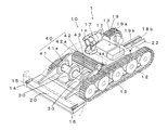
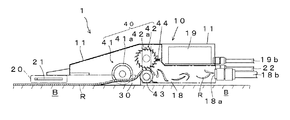
図1は本発明の実施形態に係るライニング剥離装置の斜視図で、要部を透視して見た図である。図2は本発明の実施形態に係るライニング剥離装置側面図で、内部を透視して見た図である。図3は本発明の実施形態に係るライニング剥離装置の一部拡大図である。
A lining peeling apparatus according to an embodiment of the present invention will be described with reference to the following drawings.
FIG. 1 is a perspective view of a lining peeling apparatus according to an embodiment of the present invention, and is a view seen through a main part. FIG. 2 is a side view of the lining peeling apparatus according to the embodiment of the present invention, and is a view seen through the inside. FIG. 3 is a partially enlarged view of the lining peeling apparatus according to the embodiment of the present invention.
図1を参照して、本発明の実施形態に係るライニング剥離装置1は、走行車10と、該走行車10に搭載される高周波加熱コイル20と、スクレーパ30と、切断カッター40とを有する。
Referring to FIG. 1, a
ここで基材Bとライニング材Rについて、図2を参照して説明する。
基材Bは、例えば鋼鉄製のタンクの内部表面を構成する基材である。この基材Bは、前提として、高周波誘導加熱が可能な材料で構成されている必要がある。そして基材Bの表面にライニング材Rが、接着剤を介在して或いは介在することなく、張設されて、被膜されている。
ライニング材Rとしては、ゴム、プラスチックを含む高分子材料が対象となる。より具体的には、各種の天然ゴムやクロロプレンゴム等の合成ゴムが対象となる。ゴムの耐熱性は、例えば70〜150℃程度であるが、短時間(数十分)であれば、200〜300℃でも変化しない状態に維持できる。またタールエポキシ、ポリエチレン、ポリウレタン、FRP等のプラスチックによるライニング材が対象となる。プラスチックは、熱可塑性のものの他、熱硬化性のものも対象となる。
これらのライニング材Rは、耐食、耐摩耗等の種々の目的で、例えば各種タンクの内壁面やその他の場所において、基材B表面の被覆に用いられる。
ライニング材Rがゴムの場合は、一般には共糊を呼ばれる同じゴムを溶解させた接着剤によって基材Bに接着される。
接着剤は、必ずしも前記共糊である必要はない。が、ライニング材Rに先立って熱の伝達を基材Bから受けることで軟化し、剥離し易くなるものが対象として好ましい。例えば基材Bの表面が200〜300℃程度に加熱されたときに、それからの伝熱により100〜200℃に加熱されることで剥離が容易となるような接着剤が対象として好ましい。
Here, the base material B and the lining material R will be described with reference to FIG.
The base material B is a base material that constitutes the inner surface of a steel tank, for example. As a premise, this base material B needs to be made of a material capable of high-frequency induction heating. The lining material R is stretched and coated on the surface of the base material B with or without an adhesive.
As the lining material R, polymer materials including rubber and plastic are targeted. More specifically, synthetic rubbers such as various natural rubbers and chloroprene rubbers are targeted. The heat resistance of rubber is, for example, about 70 to 150 ° C., but can be maintained in a state that does not change even at 200 to 300 ° C. for a short time (tens of minutes). Moreover, the lining material by plastics, such as tar epoxy, polyethylene, a polyurethane, and FRP, becomes object. In addition to thermoplastics, plastics are also subject to thermosetting.
These lining materials R are used for coating the surface of the base material B for various purposes such as corrosion resistance and wear resistance, for example, on the inner wall surface of various tanks and other places.
When the lining material R is rubber, it is bonded to the base material B by an adhesive in which the same rubber called co-glue is dissolved.
The adhesive does not necessarily need to be the co-glue. However, it is preferable as a target to be softened by receiving heat from the base material B prior to the lining material R and easily peeled off. For example, when the surface of the base material B is heated to about 200 to 300 ° C., an adhesive that can be easily peeled by being heated to 100 to 200 ° C. by heat transfer from the substrate B is preferable as a target.
走行車10は、自走式の車体11の両側に複数のマグネット車輪12を設けている。マグネット車輪12には移動体であるクローラ13を取り付けている。マグネット車輪12とすることで、鉄系材料等の磁石に吸着する材料で構成された基材Bに対して、確実に接地して、その移動を行うことができる。勿論、基材B表面を、重力に反して、垂直方向にも、また天井面であっても走行することが可能である。またクローラ13により、基材表面を確実にとらえて安定して走行することができる。
また走行車10は、前記車体11の前部に、走行中に前方の障害物等との接触を感知するタッチセンサー14を、バンパー形状で設けている。またタッチセンサー14の両端には前方の目標物及び地点距離を感知測定する距離センサー15を設けている。これらタッチセンサー14、距離センサー15を設けることで、障害物に対する安全停止や迂回走行を行うことができる。
The traveling
Further, the traveling
走行車10には、車体11の屋上に走行する前方を明るくする照明16と、走行する前方を視野できる監視カメラ17とが設けられており、これらによって外部からタンク内等の基材Bの周辺をモニターで見ながら、走行車の走行や、高周波加熱コイル20、切断カッター40による作業を遠隔操作できるように構成されている。
The traveling
走行車10の車体11の車内後部には、ダストケース18(図2参照)を設けている。該ダストケース18の後部の排出口18aに対して排出パイプ18bを接続し、これによってダストケース18内に収容された剥離されたライニング材を走行車10から外部へ排出できるように構成している。
A dust case 18 (see FIG. 2) is provided at the rear of the
走行車10の車体11の車内後部に、遠隔操作を行うための通信制御装置19を設けている。また前記車体11の車外後部にアンテナ19aと、後方に延伸する通電コード19bとを設けている。これによって走行車10と外部の遠隔操作部との間で双方向の通信ができるようにしている。
A
前記高周波加熱コイル20は、走行車10の前部に設けている。この高周波加熱コイル20は、例えば銅製中空角管21を平面コイル状に配置し、その周囲を絶縁、断熱被覆して構成することができる。高周波加熱コイル20は基材Bに対して平行に対面するように構成されている。高周波加熱コイル20の幅は、例えば前記走行車10の前記マグネット車輪12の車間幅より少し広い幅としている。
高周波加熱コイル20は、前記基材Bとの対面距離を調節できるよう、周知の位置調節手段により取り付けることができる。これによって、該基材Bに対する加熱温度や加熱速度を変化させることができる。
勿論、高周波加熱コイル20は平面形状の他、前記基材Bの表面形状に対応して均一な加熱を基材Bに与えることができるようにした曲面形状や、その他の形状とすることができる。
The high-
The high-
Of course, the high-
高周波加熱コイル20には高周波電流が流される。これによって高周波加熱コイル20と対面する基材Bが誘導加熱される。そしてこの基材Bの加熱によってライニング材Rが基材Bから剥がれ易くなる。
走行車10の移動に伴って高周波加熱コイル20がライニング材Rの表面をなぞるような状態で移動し、出力された高周波によって基材B表面が次々と加熱され、ライニング材Rが走行方向に順次剥がれ易くなる。
A high frequency current is passed through the high
As the traveling
高周波加熱コイル20は、例えば220Vの電圧の電源を用い、また周波数を10kHz〜40kHz、出力を数十kwとすることができる。高周波加熱コイル20の出力を調整することで、基材Bに対する加熱温度、加熱速度を調整することができる。
高周波加熱コイル20の銅製中空角管21には、冷却水を循環させている。冷却水は、前記走行車10の車体11の後部に接続される冷却水循環チューブ22を介して銅製中空角管21内に循環される。
The high-
Cooling water is circulated through the copper hollow
図3も参照して、スクレーパ30は、前記高周波加熱コイル20の後方にあって、先端が薄く後方に行くにつれて厚くなるような形状で、略楔形の断面形状にしている。
スクレーパ30は、その先端部で基材Bと該基材B上面を被覆するライニング材Rとの間に侵入し、前記走行車10の走行に伴って両者を剥離していく。
スクレーパ30は、ライニング材Rを剥離できるように、1個乃至複数個が並列配置される。剥離幅が狭くてよい場合は1個のスクレーパで十分であるが、剥離幅を大きくする場合には複数のスクレーパを並列配置する必要がある。なお、スクレーパ30の幅は前記高周波加熱コイル20の幅より少し狭い幅とするが、本実施形態では前記クローラ13、13間に配置されている。
スクレーパ30によって剥離されたライニング材Rは、スクレーパ30の上面に沿ってガイドされながら、次第に剥離間隔を大きくされ、切断カッター40に導かれる。
Referring also to FIG. 3, the
The
One or
The lining material R peeled off by the
切断カッター40は、前記スクレーパ30で剥離されたライニング材Rの幅に合わせて走行方向に縦切りする縦切カッター41と、その後に更に剥離されたライニング材Rを横方向に切断する横切カッター42とを有する。
The
前記縦切カッター41は、走行切断がし易い円盤状刃41aを軸の周りに設けている。この円盤状刃41aは、スクレーパ30で剥離されたライニング材Rの剥離幅にほぼ合わせて切断できるように、少なくとも一対が設けられることになる。また剥離されるライニング材Rの幅の大きさに応じて、円盤状刃41aの数を増やすことができる。本実施形態では、中央部に1枚追加した3枚の刃としている。3枚刃とすることで、剥離されたライニング材Rの長手方向での幅を更に半分に縦切りすることができる。
また縦切カッター41の円盤状刃41aは、スクレーパ30の途中位置に隣接するようにして配置される。本実施形態では、並列された2つのスクレーパ30の間に1つと、両側に2つで、計3つの円盤状刃41aがスクレーパ30の途中に隣接して設けられている。
縦切カッター41は、前記円盤状刃41aが走行方向に回動して、前記スクレーパ30の上面を案内されてきたライニング材Rを切断することができる。この際、スクレーパ30によって剥離されたライニング材Rの剥離間隔が大きく確保されることで、基材Bに円盤状刃41aが当ることなく、剥離されたライニング材Rの切断を確実に行うことができる。
The
Further, the disc-shaped blade 41 a of the
The
前記横切カッター42は、前記縦切カッター41で切断された前記ライニング材Rを、更に排出し易いように幅方向に切断するカッターである。
横切カッター42は、円筒状の軸の外周側に多数の横刃42aを歯車の如く備えたカッターである。この横切カッター42は前記縦切カッター41で縦切りされた剥離されたライニング材Rの幅よりも少し広い幅をもつ1つのカッターとして設けられている。
前記横切カッター42に対して、その下に案内ローラ43が設けられている。
前記スクレーパ30の後端部は前記案内ローラ43の直前まで延長されて設けられており、スクレーパ30によって案内されてきた縦切り済みのライニング材Rを、案内ローラ43に引き継ぐようになされている。
案内ローラ43は、スクレーパ30上を後方へ移動されてきた剥離されたライニング材Rを、ローラ上に載せて案内し、前記横切カッター42に噛み込ませる。
The
The
A
The rear end portion of the
The
横切カッター42には、該横切カッター42の後方に近接する前記走行車10の車体11の側壁に、前記ライニング材Rの切断塵を取り除く塵取りブラシ44を設けている。
横切カッター42で幅方向に細かく横切りされた前記ライニング材Rは、該横切カッター42の後方のダストケース18に収集される。
ダストケース18に収容された細切れのライニング材Rは、排出口18aから前記排出パイプ18b内に吸引されて、外部に排出される構成とされている。
The
The lining material R finely crossed in the width direction by the
The lining material R accommodated in the
なお前記縦切カッター41と横切カッター42とからなる切断カッター40は、それらを前進方向に回転させることで、ライニング材Rの切断を行う際に、それらカッター41、42がスクレーパ30との間でライニング材Rを挟み込むような状態となり、或いはライニング材Rを引き込むような状態となるため、走行車10の自走がより確実に、安定して行われる。
The
本発明の装置の使用例として、例えばタンク内での使用について説明する。
まず本装置1の走行車10をタンク内に搬入する。そしてタンク内の壁面を構成する基材Bに配置された走行車10を、外部からモニターを見ながら遠隔操作によって走行を開始させる。次に高周波加熱コイル20をオンして、高周波電力を加え、また高周波加熱コイル20の冷却水の循環を開始させる。また縦切カッター41、横切カッター42を回転動作させる。また前記排出パイプ18bによる吸引を開始させる。これらのスイッチ動作は、高周波加熱コイル20のオンにより自動的に引き続いて行われるようにしておくこともできる。
スクレーパ30は、その配置を退避位置と剥離位置とに調整できるようにしている場合には、その先端部を剥離位置、即ち基材Bとライニング材Rとの間に臨む位置、に調整しておく。
走行車10の走行速度は、例えば5m/分程度とする。
また高周波加熱コイル20に対面する基材Bの領域が、走行車10の移動と共に100〜200℃程度に加熱されるように、高周波加熱コイル20の周波数と電力を調整しておく。
このようにすることで、走行車10の走行と共に基材Bの対応する領域が100〜200℃に加熱され、これによってライニング材Rと前記基材Bとの接着面が剥がれ易くなる。よってスクレーパ30が前記ライニング材Rと前記基材Bとの間に容易に侵入し、前記走行車10の走行速度に合わせらがらライニング材Rを剥離してゆく。剥離された前記ライニング材Rは、前記スクレーパ30と列設した縦切カッター41で長手方向に切断され、更に前記横切カッター42によって細かく切断される。細かく切断された前記ライニング材Rは、前記車体11後部のダストケース18に収容され、更に排出パイプ18bに吸引されて、外部に排出される。
As an example of use of the apparatus of the present invention, for example, use in a tank will be described.
First, the traveling
When the
The traveling speed of the traveling
Moreover, the frequency and electric power of the high
By doing in this way, the area | region which the base material B respond | corresponds with driving | running | working of the traveling
1 ライニング剥離装置
10 走行車
11 車体
12 マグネット車輪
13 クローラ
14 タッチセンサー
15 距離センサー
16 照明
17 カメラ
18 ダストケース
18a 排出口
18b 排出パイプ
19 通信制御装置
19a アンテナ
19b 通電コード
20 高周波加熱コイル
21 銅製中空角管
22 冷却水循環チューブ
30 スクレーパ
40 切断カッター
41 縦切カッター
41a 円盤状刃
42 横切カッター
42a 横刃
43 案内ローラ
44 塵取りブラシ
B 基材
R ライニング材
DESCRIPTION OF
Claims (5)
Priority Applications (1)
| Application Number | Priority Date | Filing Date | Title |
|---|---|---|---|
| JP2007117887A JP2008272995A (en) | 2007-04-27 | 2007-04-27 | Lining releasing apparatus |
Applications Claiming Priority (1)
| Application Number | Priority Date | Filing Date | Title |
|---|---|---|---|
| JP2007117887A JP2008272995A (en) | 2007-04-27 | 2007-04-27 | Lining releasing apparatus |
Publications (1)
| Publication Number | Publication Date |
|---|---|
| JP2008272995A true JP2008272995A (en) | 2008-11-13 |
Family
ID=40051600
Family Applications (1)
| Application Number | Title | Priority Date | Filing Date |
|---|---|---|---|
| JP2007117887A Pending JP2008272995A (en) | 2007-04-27 | 2007-04-27 | Lining releasing apparatus |
Country Status (1)
| Country | Link |
|---|---|
| JP (1) | JP2008272995A (en) |
Cited By (3)
| Publication number | Priority date | Publication date | Assignee | Title |
|---|---|---|---|---|
| JP2017113961A (en) * | 2015-12-24 | 2017-06-29 | 高六商事株式会社 | Coating peeling apparatus |
| JP2017121747A (en) * | 2016-01-07 | 2017-07-13 | 高六商事株式会社 | Coating peeling device |
| WO2019142435A1 (en) | 2018-01-18 | 2019-07-25 | 株式会社Ihi | Lining material peeling method |
Citations (4)
| Publication number | Priority date | Publication date | Assignee | Title |
|---|---|---|---|---|
| JPS61106807A (en) * | 1984-10-30 | 1986-05-24 | 株式会社新潟鐵工所 | Blade apparatus in asphalt paving working apparatus |
| JPH06226742A (en) * | 1993-02-03 | 1994-08-16 | Mitsubishi Heavy Ind Ltd | Regeneration treatment of painted plastic |
| JPH07214557A (en) * | 1994-02-03 | 1995-08-15 | Yazaki Kako Kk | Separately recovering method for steel tube and covering resin of resin-covered steel tube |
| JP2005126623A (en) * | 2003-10-27 | 2005-05-19 | Konica Minolta Medical & Graphic Inc | Method for recovering polyester-based resin substrate |
-
2007
- 2007-04-27 JP JP2007117887A patent/JP2008272995A/en active Pending
Patent Citations (4)
| Publication number | Priority date | Publication date | Assignee | Title |
|---|---|---|---|---|
| JPS61106807A (en) * | 1984-10-30 | 1986-05-24 | 株式会社新潟鐵工所 | Blade apparatus in asphalt paving working apparatus |
| JPH06226742A (en) * | 1993-02-03 | 1994-08-16 | Mitsubishi Heavy Ind Ltd | Regeneration treatment of painted plastic |
| JPH07214557A (en) * | 1994-02-03 | 1995-08-15 | Yazaki Kako Kk | Separately recovering method for steel tube and covering resin of resin-covered steel tube |
| JP2005126623A (en) * | 2003-10-27 | 2005-05-19 | Konica Minolta Medical & Graphic Inc | Method for recovering polyester-based resin substrate |
Cited By (5)
| Publication number | Priority date | Publication date | Assignee | Title |
|---|---|---|---|---|
| JP2017113961A (en) * | 2015-12-24 | 2017-06-29 | 高六商事株式会社 | Coating peeling apparatus |
| JP2017121747A (en) * | 2016-01-07 | 2017-07-13 | 高六商事株式会社 | Coating peeling device |
| WO2019142435A1 (en) | 2018-01-18 | 2019-07-25 | 株式会社Ihi | Lining material peeling method |
| KR20200051820A (en) | 2018-01-18 | 2020-05-13 | 가부시키가이샤 아이에이치아이 | Lining material peeling method |
| US11097528B2 (en) | 2018-01-18 | 2021-08-24 | Ihi Corporation | Lining material peeling method |
Similar Documents
| Publication | Publication Date | Title |
|---|---|---|
| US20210229138A1 (en) | Machine for spraying a section of pipeline | |
| JP4330639B2 (en) | Asphalt pavement removal method, asphalt pavement removal system, electromagnetic induction coil unit, asphalt pavement removal apparatus, and peeling method | |
| US7571557B2 (en) | Ice-removing device | |
| EP3312418B1 (en) | A method and system for performing maintenance such as de-icing of a rotor blade of a wind turbine rotor | |
| WO2014006495A1 (en) | Method of and system for removing material from a cut-joint using a laser beam and a wire | |
| CN107994529B (en) | Combined intelligent snow melting and deicing device and method based on unmanned aerial vehicle | |
| JP2008272995A (en) | Lining releasing apparatus | |
| JPS585122B2 (en) | Internal deburring, cleaning and coating equipment for pressure welding long medium and small diameter pipes | |
| RU2009128891A (en) | METHOD AND DEVICE FOR LAYING PIPELINES IN SOIL | |
| WO2014190438A1 (en) | System, method and apparatus for removing a burr from a slotted pipe | |
| CN108798776B (en) | Tunnel drain pipe deicing device supervised by Internet | |
| CN112576268B (en) | Hard rock tunneling device and hard rock tunneling method | |
| DE502007002249D1 (en) | Industrial truck with a device for the lateral extraction of a power supply unit | |
| KR20070108484A (en) | Cutting equipement and cutting method using super low-temperature gas | |
| WO2013113002A2 (en) | A method to control the environment in a laser path | |
| CN112539068B (en) | Rock-breaking shield machine system with temperature difference as auxiliary measure and operation method | |
| JP2009255403A (en) | Wire saw cutting method and wire saw cutter | |
| CN103410113B (en) | A kind of deicing vehicle | |
| CN107059514A (en) | Multi-functional rail bonding drill | |
| WO2019097723A1 (en) | Snow removal method for solar panels, solar panel snow removal device, and solar panel snow remover | |
| US2007225A (en) | Electric arc cutting machine | |
| JP2012172363A (en) | Demolition machine | |
| CN114427209A (en) | Deicing system based on interface flexible melting and stripping technology | |
| CN115625164A (en) | Obstacle clearing robot and operation method thereof | |
| CN220430462U (en) | Deicing and snow removing integrated device for ship deck |
Legal Events
| Date | Code | Title | Description |
|---|---|---|---|
| A621 | Written request for application examination |
Free format text: JAPANESE INTERMEDIATE CODE: A621 Effective date: 20100319 |
|
| A977 | Report on retrieval |
Free format text: JAPANESE INTERMEDIATE CODE: A971007 Effective date: 20111117 |
|
| A131 | Notification of reasons for refusal |
Free format text: JAPANESE INTERMEDIATE CODE: A131 Effective date: 20111129 |
|
| A02 | Decision of refusal |
Free format text: JAPANESE INTERMEDIATE CODE: A02 Effective date: 20120417 |