EP3740435B1 - Schliessvorrichtung - Google Patents
Schliessvorrichtung Download PDFInfo
- Publication number
- EP3740435B1 EP3740435B1 EP19704922.4A EP19704922A EP3740435B1 EP 3740435 B1 EP3740435 B1 EP 3740435B1 EP 19704922 A EP19704922 A EP 19704922A EP 3740435 B1 EP3740435 B1 EP 3740435B1
- Authority
- EP
- European Patent Office
- Prior art keywords
- ring
- top wall
- legs
- container
- cover
- Prior art date
- Legal status (The legal status is an assumption and is not a legal conclusion. Google has not performed a legal analysis and makes no representation as to the accuracy of the status listed.)
- Active
Links
- 210000002105 tongue Anatomy 0.000 claims description 38
- 229920001971 elastomer Polymers 0.000 claims description 33
- 239000000806 elastomer Substances 0.000 claims description 33
- 238000000034 method Methods 0.000 claims description 25
- 230000002093 peripheral effect Effects 0.000 claims description 24
- 230000000994 depressogenic effect Effects 0.000 claims description 13
- 230000000717 retained effect Effects 0.000 claims description 11
- 239000000463 material Substances 0.000 claims description 8
- -1 polypropylene Polymers 0.000 claims description 8
- 238000007789 sealing Methods 0.000 claims description 8
- 239000004743 Polypropylene Substances 0.000 claims description 5
- 229920001155 polypropylene Polymers 0.000 claims description 5
- 230000008878 coupling Effects 0.000 claims description 4
- 238000010168 coupling process Methods 0.000 claims description 4
- 238000005859 coupling reaction Methods 0.000 claims description 4
- 239000012815 thermoplastic material Substances 0.000 claims description 2
- 230000008569 process Effects 0.000 description 19
- 238000004108 freeze drying Methods 0.000 description 7
- 239000000126 substance Substances 0.000 description 7
- 239000011521 glass Substances 0.000 description 4
- 238000003780 insertion Methods 0.000 description 4
- 230000037431 insertion Effects 0.000 description 4
- 229920000139 polyethylene terephthalate Polymers 0.000 description 4
- 239000005020 polyethylene terephthalate Substances 0.000 description 4
- WSFSSNUMVMOOMR-UHFFFAOYSA-N Formaldehyde Chemical compound O=C WSFSSNUMVMOOMR-UHFFFAOYSA-N 0.000 description 3
- 239000004698 Polyethylene Substances 0.000 description 3
- 229920001903 high density polyethylene Polymers 0.000 description 3
- 239000004700 high-density polyethylene Substances 0.000 description 3
- 239000007788 liquid Substances 0.000 description 3
- 229920003023 plastic Polymers 0.000 description 3
- 239000004033 plastic Substances 0.000 description 3
- 229920000573 polyethylene Polymers 0.000 description 3
- IISBACLAFKSPIT-UHFFFAOYSA-N bisphenol A Chemical compound C=1C=C(O)C=CC=1C(C)(C)C1=CC=C(O)C=C1 IISBACLAFKSPIT-UHFFFAOYSA-N 0.000 description 2
- 238000004891 communication Methods 0.000 description 2
- 239000007789 gas Substances 0.000 description 2
- 238000004519 manufacturing process Methods 0.000 description 2
- 230000001954 sterilising effect Effects 0.000 description 2
- 238000004659 sterilization and disinfection Methods 0.000 description 2
- 241000894006 Bacteria Species 0.000 description 1
- 239000004676 acrylonitrile butadiene styrene Substances 0.000 description 1
- 239000004480 active ingredient Substances 0.000 description 1
- 230000008901 benefit Effects 0.000 description 1
- 239000000919 ceramic Substances 0.000 description 1
- 239000000356 contaminant Substances 0.000 description 1
- 239000003085 diluting agent Substances 0.000 description 1
- 239000003814 drug Substances 0.000 description 1
- 229940079593 drug Drugs 0.000 description 1
- 229940126534 drug product Drugs 0.000 description 1
- 238000001035 drying Methods 0.000 description 1
- 230000000694 effects Effects 0.000 description 1
- 230000008020 evaporation Effects 0.000 description 1
- 238000001704 evaporation Methods 0.000 description 1
- 238000005429 filling process Methods 0.000 description 1
- 230000008676 import Effects 0.000 description 1
- 238000005304 joining Methods 0.000 description 1
- 239000006193 liquid solution Substances 0.000 description 1
- 238000012792 lyophilization process Methods 0.000 description 1
- 238000012986 modification Methods 0.000 description 1
- 230000004048 modification Effects 0.000 description 1
- 238000004806 packaging method and process Methods 0.000 description 1
- 239000002245 particle Substances 0.000 description 1
- 239000000825 pharmaceutical preparation Substances 0.000 description 1
- 239000000843 powder Substances 0.000 description 1
- 238000004321 preservation Methods 0.000 description 1
- 238000003825 pressing Methods 0.000 description 1
- 238000012545 processing Methods 0.000 description 1
- 239000002904 solvent Substances 0.000 description 1
- 238000000859 sublimation Methods 0.000 description 1
- 230000008022 sublimation Effects 0.000 description 1
- XLYOFNOQVPJJNP-UHFFFAOYSA-N water Substances O XLYOFNOQVPJJNP-UHFFFAOYSA-N 0.000 description 1
Images


Classifications
-
- B—PERFORMING OPERATIONS; TRANSPORTING
- B65—CONVEYING; PACKING; STORING; HANDLING THIN OR FILAMENTARY MATERIAL
- B65D—CONTAINERS FOR STORAGE OR TRANSPORT OF ARTICLES OR MATERIALS, e.g. BAGS, BARRELS, BOTTLES, BOXES, CANS, CARTONS, CRATES, DRUMS, JARS, TANKS, HOPPERS, FORWARDING CONTAINERS; ACCESSORIES, CLOSURES, OR FITTINGS THEREFOR; PACKAGING ELEMENTS; PACKAGES
- B65D51/00—Closures not otherwise provided for
- B65D51/002—Closures to be pierced by an extracting-device for the contents and fixed on the container by separate retaining means
-
- B—PERFORMING OPERATIONS; TRANSPORTING
- B65—CONVEYING; PACKING; STORING; HANDLING THIN OR FILAMENTARY MATERIAL
- B65D—CONTAINERS FOR STORAGE OR TRANSPORT OF ARTICLES OR MATERIALS, e.g. BAGS, BARRELS, BOTTLES, BOXES, CANS, CARTONS, CRATES, DRUMS, JARS, TANKS, HOPPERS, FORWARDING CONTAINERS; ACCESSORIES, CLOSURES, OR FITTINGS THEREFOR; PACKAGING ELEMENTS; PACKAGES
- B65D51/00—Closures not otherwise provided for
- B65D51/18—Arrangements of closures with protective outer cap-like covers or of two or more co-operating closures
- B65D51/20—Caps, lids, or covers co-operating with an inner closure arranged to be opened by piercing, cutting, or tearing
-
- B—PERFORMING OPERATIONS; TRANSPORTING
- B65—CONVEYING; PACKING; STORING; HANDLING THIN OR FILAMENTARY MATERIAL
- B65D—CONTAINERS FOR STORAGE OR TRANSPORT OF ARTICLES OR MATERIALS, e.g. BAGS, BARRELS, BOTTLES, BOXES, CANS, CARTONS, CRATES, DRUMS, JARS, TANKS, HOPPERS, FORWARDING CONTAINERS; ACCESSORIES, CLOSURES, OR FITTINGS THEREFOR; PACKAGING ELEMENTS; PACKAGES
- B65D51/00—Closures not otherwise provided for
- B65D51/24—Closures not otherwise provided for combined or co-operating with auxiliary devices for non-closing purposes
- B65D51/241—Closures not otherwise provided for combined or co-operating with auxiliary devices for non-closing purposes provided with freeze-drying means
Definitions
- a closure device for closing a container which in one embodiment, includes a preassembled stopper. Another embodiment relates to a container equipped with such a closure device. Another embodiment relates to a method of closing and sealing a container using such a closure device. Such device is disclosed in FR 2 927 316 A1 . Additional prior art is disclosed in WO 2017/001459 A1 and WO 2011/039004 A1 .
- a glass bottle In the field of containers for medication, a glass bottle can be used to store an active ingredient in freeze-dried form, in powder form, or in the form of a liquid solution. Such a bottle must be closed off in a leak-tight manner, so as to maintain its contents in a satisfactory state of preservation, until the date on which it is used.
- a closure device can be used that comprises an elastomer stopper that has the function of being totally sealed against gas, liquids, and bacteria.
- a locking cover can be made of a plastic material, and that is designed to be held in place around the stopper so as to isolate the stopper from the outside and so as to oppose removal of the stopper.
- each container is filled with a quantity of substance for freeze-drying, and then the respective stopper is placed on or in the neck of the container in such a manner as to be secured thereto, while also preserving communication between the outside environment and the inside of the container.
- Containers filled and pre-stopped in this way are then placed in batches on the shelves of a freeze drier inside which the substances are dehydrated.
- vacuum cold-drying is performed to help ensure that the water is extracted from the substance by sublimation and evaporation.
- stopper device which provides for secure and stable positioning of the cover on a vial stopper.
- An embodiment of the invention relates to a closure device for closing a container.
- the closure device comprises a ring, a cover and a cap.
- the ring comprises a first top wall and a flexible skirt extending downwardly from the first top wall.
- the first top wall defines a first central through-opening.
- the flexible skirt comprises a plurality of spaced-apart first legs and a plurality of spaced-apart second legs. Each of the first and second legs has a first end at the first top wall and an opposing second end.
- the plurality of spaced-apart first legs are different from the plurality of spaced-apart second legs.
- each first leg has a first inwardly protruding ledge between the first and second ends and an exterior surface of each first leg has a first outwardly protruding ledge between the first and second ends.
- Each second leg has a second inwardly protruding ledge at the second end.
- An interior surface of each second leg has a flexible tongue and a recess configured to receive the flexible tongue.
- the cover comprises a second top wall, a sidewall extending downwardly from the second top wall and an interior cavity defined by the second top wall and the sidewall.
- the second top wall defines a second central through-opening generally aligned with the first central through-opening of the ring.
- An interior surface of the sidewall includes a third inwardly protruding ledge.
- a cap has a raised peripheral rim and a central depressed region.
- An interior surface of the central depressed region includes a plurality of spaced-apart bent tabs configured to be engaged in the second central through-opening of the cover to couple the cap to the cover.
- the third inwardly protruding ledge of the cover engages the first top wall of the ring.
- the third inwardly protruding ledge of the cover engages the first outwardly protruding ledge of each first leg of the ring.
- the assembly comprises a container and a closure device for closing and sealing the container.
- the container has a main body, a neck, and a rim defining an opening of the container.
- the closure device comprises a ring, an elastomer stopper, a cover and a cap.
- the ring comprises a first top wall, a flexible skirt extending downwardly from the first top wall and a first interior cavity defined by the first top wall and the flexible skirt.
- the first top wall defines a first central through-opening.
- the flexible skirt comprises a plurality of spaced-apart first legs and a plurality of spaced-apart second legs.
- Each of the first and second legs has a first end at the first top wall and an opposing second end.
- the plurality of spaced-apart first legs are different from the plurality of spaced-apart second legs.
- An interior surface of each first leg has a first inwardly protruding ledge between the first and second ends and an exterior surface of each first leg has a first outwardly protruding ledge between the first and second ends.
- Each second leg has a second inwardly protruding ledge at the second end, and an interior surface of each second leg has a flexible tongue and a recess configured to receive the flexible tongue.
- the elastomer stopper has a head and a cylindrical body extending downwardly from the head.
- the cover comprises a second top wall, a sidewall extending downwardly from the second top wall and a second interior cavity defined by the second top wall and the sidewall.
- the second top wall defines a second central through-opening generally aligned with the first central through-opening of the ring.
- An interior surface of the sidewall including a third inwardly protruding ledge.
- the cap has a raised peripheral rim and a central depressed region.
- An inner surface of the central depressed region includes a plurality of spaced-apart bent tabs configured to be engaged in the central through-opening of the cover to couple the cap to the cover.
- the container has a main body, a neck, and a rim defining an opening of the container.
- the closure device comprises a ring, an elastomer stopper, a cover and a cap.
- the ring comprises a first top wall, a flexible skirt extending downwardly from the first top wall and a first interior cavity defined by the first top wall and the flexible skirt.
- the first top wall defines a first central through-opening.
- the flexible skirt comprises a plurality of spaced-apart first legs and a plurality of spaced-apart second legs. Each of the first and second legs has a first end at the first top wall and an opposing second end.
- the plurality of spaced-apart first legs are different from the plurality of spaced-apart second legs.
- An interior surface of each first leg has a first inwardly protruding ledge between the first and second ends, and an exterior surface of each first leg has a first outwardly protruding ledge between the first and second ends.
- Each second leg has a second inwardly protruding ledge at the second end.
- An interior surface of each second leg has a flexible tongue and a recess configured to receive the flexible tongue.
- the elastomer stopper has a head and a cylindrical body extending downwardly from the head.
- the cover comprises a second top wall, a sidewall extending downwardly from the second top wall and a second interior cavity defined by the second top wall and the sidewall.
- the second top wall defines a second central through-opening generally aligned with the first central through-opening of the ring.
- An interior surface of the sidewall includes a third inwardly protruding ledge.
- the cap has a raised peripheral rim and a central depressed region.
- An inner surface of the central depressed region includes a plurality of spaced-apart bent tabs configured to be engaged in the central through-opening of the cover to couple the cap to the cover.
- the method comprises: assembling the closure device by coupling the cap to the cover such that the spaced-apart bent tabs of the cap are engaged with an underside of the second top wall of the cover, coupling the ring and the elastomer stopper by inserting the elastomer stopper into the first interior cavity of the ring such that the flexible tongues of the second legs of the ring engage an underside of the head of the elastomer stopper, inserting the coupled ring and elastomer stopper into the second interior cavity of the cover such that the third inwardly protruding ledge of the cover abuts an underside of a peripheral rim of the first top wall of the ring; placing the assembled closure device on the rim of the container in a first position by inserting the container into the first interior cavity of the ring, such that the rim of the container is retained between the first inwardly protruding ledges of the first legs and the second inwardly protruding ledges of the second legs of the ring and such
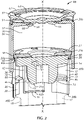
- a closure device generally designated by the reference numeral 10, positioned on a container 12 for closure of the container 12 in a leak-tight and secure manner.
- the container 12 has a main body 16 (see Fig. 3 ), a neck 18 extending from an upper end of the main body 16, and a rim 20 defining an opening 22 of the container 12 in communication with the neck 18 and body 16.
- the container 12 may be made of a glass, ceramic or a polymeric material, such as polyethylene (PE) polyethylene terephthalate (PET), glycol-modified polyethylene terephthalate (PETG), high density polyethylene (PEHD) and the like.
- the closure device 10 shown in Figs. 1-4 includes a stopper 14 assembled thereto.
- the stopper 14 is configured to be positioned at least partially in the container 12.
- the stopper 14 is an elastomer stopper
- the stopper 14 is substantially T-shaped in cross-section, and has a cylindrical body 24 and a head 26.
- the cylindrical body 24 is designed to be positioned within the neck 18 of the container 12.
- a free end 24a of the cylindrical body 24 is preferably tapered.
- the head 26 defines a peripheral flange for abutting against the top surface of the rim 20 of the container 12.
- the closure device 10 is configured to cover the rim 20 and neck 18 of the container 12 with at least a portion of the stopper 14 positioned therein.
- the closure device 10, and more particularly each component of the closure device 10 as described in detail herein, is preferably made of a plastic material, and more preferably a thermoplastic material such as, but not limited to, PE, PET, PETG, PEHD, polypropylene (PP) or acrylonitrile butadiene styrene (ABS). More preferably, the closure device 10 is made of a pharma grade polypropylene material, and more particularly a pharma grade polypropylene material that is free of contaminants or critical substances (e.g., bisphenol A or formaldehyde).
- the closure device 10 comprises a ring 28, a cover 30, and a cap or sealing button 32.
- the ring 28 has a cylindrical shape has a first end 28a and an opposing second end 28b.
- the ring 28 comprises a top wall 34 at its first end 28a and cylindrical skirt or sidewall 36, and more particularly a cylindrical skirt or sidewall 36, extending downwardly from the top wall 34 away from the first end 28a.
- the ring 28 has an interior cavity 37 defined by the top wall 34 and the skirt 36.
- the second end 28b of the ring 28 is an open end.
- the top wall 34 includes an opening 29 at its geometric center. The central opening 29 extends completely through the top wall 34 and is configured to be generally aligned with the opening 22 of the container 12.
- the top wall 34 has a diameter that is substantially the same as or at least slightly greater than a diameter of the skirt 36.
- the diameter of the top wall 34 is at least slightly greater than the diameter of the skirt 36, such that a peripheral rim 38 of the top wall 34 juts out from a vertical plane of the skirt 36 and defines a peripheral flange.
- the skirt 36 is preferably comprised of a plurality of spaced-apart first walls or legs 40 and a plurality of spaced-apart second walls or legs 42.
- the plurality of spaced-apart first legs 40 includes three first legs 40 and the plurality of spaced-apart second legs 42 includes three second legs 42, meaning a total of six spaced-apart first and second legs 40, 42 form the skirt 36.
- Each first leg 40 and each second leg 42 has a first or proximal end 40a, 42a integrally formed with or attached to the top wall 34 and an opposing second or distal end 40b, 42b which is a free end.
- the first and second legs 40, 42 are elastically deformable, and more particularly radially deformable (inwardly or outwardly) relative to a central longitudinal axis X of the skirt 36.
- the central longitudinal axis X of the skirt 36 also defines a central longitudinal axis of the overall closure device 10.
- the first and second legs 40, 42 are preferably arranged in an alternating fashion relative to each other, meaning that each first leg 40 is positioned between two of the second legs 42 and, similarly, each second leg 42 is positioned between two of the first legs 40.
- the skirt 36 is formed of alternating first legs 40 and second legs 42.
- each first leg 40 includes a rib or ledge 44 protruding inwardly toward the interior cavity 37 of the ring 28.
- Each ledge 44 defines a catch designed to engage the rim 20 of the container 12, for example, during a treatment process, and during final closure and sealing of the container 12, as described in more detail herein.
- the ledge 44 is preferably provided at an intermediate position between the first and second ends 40a, 40b of each first leg 40 (i.e., each ledge 44 is distal from both the first and second ends 40a, 40b of the respective first leg 40).
- the ledges 44 of the first legs 40 are referred to hereinafter as upper ledges 44.
- each first leg 40 includes a ledge 46 protruding outwardly away from the interior cavity 37 of the ring 28.
- the ledge 46 of each first leg 40 is provided at a corresponding position to the upper ledge 44 of the respective first leg 40.
- Such an outwardly protruding ledge 46 may also be provided on the exterior surface of each second leg 42 at the same position and orientation, such that the plurality of outwardly protruding ledges 46 collectively define an annular outwardly protruding ledge.
- each second leg 42 includes or is formed as a rib or ledge 48 which protrudes inwardly toward the interior cavity 37 of the ring 28.
- the ledge 48 of each second leg 42 defines another catch designed to engage the rim 20 of the container 12, for example, during a treatment process, as described in more detail herein.
- the ledges 48 of the second legs 42 are referred to hereinafter as lower ledges 48.
- the distance between the upper ledges 44 of the first legs 40 and the lower ledges 48 of the second legs 42 is generally equal to or at least slightly larger than the height of the rim 20 of the container 12.
- each second leg 42 further comprises a tongue 50 (alternatively may be referred to as a tab, prong, tooth and the like), and more particularly a flexible tongue 50, and a corresponding recess 52 configured to receive the tongue 50 when the tongue 50 is in a retracted configuration.
- Each tongue 50 is cantilevered and is inclined with respect to the interior surface of the respective second leg 42.
- Each tongue 50 is biased at such an incline toward the interior cavity 37 of the ring 28.
- the tongue 50 is provided at an intermediate position between the first and second ends 42a, 42b of each second leg 42. More particularly, the distance between the top wall 34 (i.e., the first ends 42a of the second legs 42) and the flexible tongues 50 is generally equal to or at least slightly larger than a height of the head 26 of the stopper 14.
- the cover 30 also has a generally cylindrical body and has a first end 30a and an opposing second end 30b.
- the cover 30 comprises a top wall 54 at its first end 30a and a skirt or sidewall 56, and more particularly a cylindrical skirt or sidewall 56, extending downwardly from the top wall 54 away from the first end 30a.
- the cover 30 has an interior cavity 57 defined by the top wall 54 and the skirt 56.
- the opposing second end 30b of the cover 30 is an open end.
- the top wall 54 is generally a closed wall, except for an opening 58 provided at its geometric center.
- the central opening 58 extends completely through the top wall 54 and is configured to be generally aligned coaxially with the opening 22 of the container 12 and the opening 29 of the ring 28.
- the interior cavity 57 of the cover 30 preferably has a diameter (i.e., inner diameter of the cover 30) that is at least slightly greater than an outer diameter of the ring 28, such that the ring 28 is configured to be received within the interior cavity 57 of the cover 30.
- An interior surface of the skirt 56 of the cover 30 preferably includes a rib or ledge 60 which protrudes inwardly toward the interior cavity 57 of the cover 30. More particularly, the ledge 60 is an annular ledge.
- the ledge 60 defines a catch designed to engage the peripheral rim 38 of the top wall 34 of the ring 28 in a first position (for example, during a treatment process), and to engage the outwardly protruding ledges 46 of the first legs 40 and/or second legs 42 in a second position (for example, in a closed or sealed position), as described in more detail herein.
- the inwardly protruding ledge 60 is preferably provided closer to the open second end 30b of the cover 30 than to the first end 30a.
- the cap 32 is preferably generally circular in cross-section, and comprises a raised peripheral rim 62 and a central depressed region 64.
- An interior surface of the central depressed region 64 includes a plurality of spaced-apart bent tabs 66 configured to be engaged in the central opening 58 of the cover 30. That is, in the engaged position, the bent tabs 66 extend through the central opening 58 and abut the underside (or interior surface) of the top wall 54 of the cover 30. As such, the bent tabs 66 serve to couple the cap 32 to the cover 30.
- the cap 32 closes off the opening 58 of the cover 30 (as well as the opening 29 of the ring 28) and, before it is removed, opposes any access to the stopper 14 via the openings 58, 29.
- the cap 32 includes an elastically deformable connecting web in the area between the peripheral rim 62 and the central depressed region 64, such that the peripheral rim 62 may be configured to move axially under drive from an axial pressure or force.
- the peripheral rim 62 may be configured to move between a raised position and a lowered position.
- the peripheral rim 62 is also be biased to the raised position, such that the peripheral rim 62 automatically returns to the raised position when a pressure or force ceases to be applied to it.
- the cap 32 functions as a spring element, and more particularly a flexible spring element, which provides for at least partial compensation of the heights of the stacked components of the assembly. More particularly, the cap 32 allows for the partial compensation of different heights of the various stacked components (e.g., the container 12, the stopper 14 and the closure device 10) of the assembly, and therefore reduces the risk of breakage of the container 12 during a treatment process. This benefit is particularly advantageous in the context of glass containers 12 being used in a lyophilization process.
- closure device 10 of the present invention may be utilized on a container made of any type of material and may be used in conjunction with a container for any type of treatment process (e.g., sterilization process, filling process and the like), and is in no way limited to glass containers and a lyophilization (freeze-drying) process.
- sterilization process e.g., sterilization process, filling process and the like
- lyophilization freeze-drying
- the stopper 14 When the cap 32 is removed by a user, a part of the upper (or exterior) surface 26b of the head 26 of the stopper 14 is exposed through the openings 58 and 29.
- the stopper 14 may thus be pierced, for example, by a needle of a syringe (not shown) for introducing a liquid solvent or diluent into the container 12 and/or drawing out a liquid drug product from the container 12.
- a description of one of the methods for assembling the closure device 10 follows. The successive steps which may be utilized for joining the closure device 10 (including the stopper 14 pre-assembled therewith) together with the container 12 (e.g., for pre-assembly or for a treatment process, in a first position) and, finally, for closing the container 12 in a sealed manner by the closure device 10 (i.e., a second position) are also described.
- the stopper 14 is positioned within the ring 28, as shown in Figs. 1-2 . More particularly, the stopper 14 is inserted into the interior cavity 37 of the ring 28 via the bottom end 28b and pushed in an upward direction toward the first end 28a and the top wall 34. By this insertion motion, the head 26 of the stopper 14 comes into contact with the surfaces of the tongues 50. As the head 26 of the stopper 14 passes over the tongues 50, the head 26 causes the tongues 50 to flex toward and retract inside of the respective recesses 52.
- the tongues 50 spring back out of the recesses 52 and return to their previously biased position (i.e., to extend inwardly toward the interior cavity 37 and out of the recesses 52), and then engage the head 26 of the stopper 14. More particularly, the tongues 50 snap back to engage the underside (i.e., the lower or interior surface 26a) of the head 26 of the stopper 14, so. as to retain the stopper 14 between the tongues 50 and the top wall 34, as shown in Figs. 1-2 .
- the upper surface 26b of the head 26 of the stopper 14 faces, and may even abut or be in direct contact with, the top wall 34 of the ring 28.
- the stopper 14 is secured within the ring 28, between and by the top wall 34 and the tongues 50 of the second legs 42 of the skirt 36 of the ring 28.
- the ring 28, with the stopper 14 secured therein is partially inserted into the interior cavity 57 of the cover 30 through the open second end 30b.
- the cap 32 prior to the partial insertion of the assembled ring 28 and stopper 14 into the interior cavity 57 of the cover 30, the cap 32 has already been coupled to the cover 30, as described above, such that the spaced-apart tabs 66 of the cap 32 are engaged with the underside of the top wall 54 of the cover 30.
- the assembled ring 28 and stopper 14 pass through the open second end 30b of the cover 30 and are pushed in an upward direction toward the top wall 54 of the cover 30 (or vice versa the cover 30 is pushed in a downward direction toward the top wall 34 of the ring 28).
- This insertion motion continues until the peripheral flange 38 of the top wall 34 of the ring 28 passes over and then comes to rest on the inwardly protruding ledge 60 of the cover 30.
- the skirt 36 of the ring 28, and more particularly the first and second legs 40, 42 may deform at least slightly radially inwardly.
- the peripheral flange 38 of the top wall 34 of the ring 28 is positioned above and on the inwardly protruding ledge 60 of the cover 30, such that ledge 60 of the cover 30 abuts and directly contacts the lower surface or underside 38a of the peripheral flange 38.
- a portion of the assembled ring 28 and stopper 14 is received within the interior cavity 57 of the cover 30, while the remaining portion of the assembled ring 28 and stopper 14 is positioned outside of the cover 30, as shown in Figs. 1-2 .
- the closure device 10 is in its assembled position or state.
- the assembled closure device 10 may then be subjected to a preliminary treatment process, such as a sterilization process.
- the assembled closure device 10 is positioned on the container 12 in a first position, as shown in Figs. 1-2 .
- the assembled closure device 10 is positioned over the container 12, such that the rim 20 of the container 12 is received within the ring 28. More particularly, the assembled closure device 10 is pushed in a downward direction over the container rim 20 (or vice versa the container 12 is pushed in an upward direction toward the top wall 34 of the ring 28) until the container rim 12 is positioned between the upper ledges 44 of the first legs 40 and the lower ledges 48 of the second legs 42 of the skirt 36 of the ring 28.
- the container rim 12 is secured within the ring 28 and serves to center the assembled closure device 10 and the container 12 relative to each other, such that the assembled closure device 10 is held in a stable manner on the container 12.
- the tapered end 24a of the cylindrical body 24 of the stopper 14 is positioned at the entry of the opening 22 of the container 12, but the cylindrical body 24 itself may not yet be fully received within the opening 22 of the container 12.
- the assembled closure device 10 and container 12 joined thereto may be subjected to one or more of a variety of treatment processes.
- the assembled closure device 10 and container 12 joined thereto, in the first position may be subjected to a lyophilization (i.e., freeze-drying) process. Because the cylindrical body 24 or the tapered end 24a of the stopper 14 is not yet inserted within the opening 22 of the container 12, gases or vapors which form during the treatment process, are able to escape from the container 12.
- the container 12 can be finally closed and sealed by the closure device 10 (i.e., placed into the second position). It will be understood by those skilled in the art that the processes described herein may be simultaneously carried out on multiple containers 12 and closure devices 10, providing for bulk assembly, treatment and closure.
- pressure or force e.g., by a pressing plate
- pressure or force may be exerted in a downward direction on the cap 32, and this pressure or force then translates through the closure device 10.
- pressure or force may be exerted in an upward direction on the container 12, which in turn exerts pressure or force in an upward direction on the closure device 10.
- the pressure/force causes the container rim 20 to come out of the annular seat defined by the upper ledges 44 of the first legs 40 and the lower ledges 48 of the second legs 42 of the ring 28, and moves in an upward direction toward the top wall 34 of the ring 28 and past the upper ledges 44 of the first legs 40 and the flexible tongues 50 of the second legs 42.
- the cylindrical body 24 of the stopper 14 simultaneously moves into the opening 22 of the container 12, and the container rim 20 comes into contact with the surfaces of the flexible tongues 50, thus causing the tongues 50 to again retract inside the respective recesses 52.
- first legs 40 deform or bend radially outwardly until the inner diameter of the upper ledges 44 equals the outer diameter of the container rim 20 of the container 12.
- the first legs 40 will deform or bend radially inwardly again, once the stopper 14 is pushed into the opening 22 of the container 12, such that the upper ledges 44 of the first legs 44 engage the underside of the container rim 20 for final container fixation.
- the relative movement between the cover 30 and the ring 28 may start once the stopper 14 is completely pushed into the opening 22 of the container 12.
- This pressure/force also causes the inwardly protruding ledge 60 of the cover 30 and the peripheral flange 38 of the ring 28 to come out of engagement with each other, and the cover 30 to move in a downward direction toward the container 12 until the inwardly protruding ledge 60 engages and abuts against the outwardly protruding ledges 46 of the ring 28, and until the top wall 34 of the ring 28 is proximate (or abuts) the top wall 54 of the cover 30.
- the closure device 10 is securely locked to the container 12, such that the container 12 is closed and sealed in a secure and leak-tight manner.
Landscapes
- Engineering & Computer Science (AREA)
- Mechanical Engineering (AREA)
- Closures For Containers (AREA)
- Medical Preparation Storing Or Oral Administration Devices (AREA)
Claims (12)
- Schließvorrichtung (10) zum Schließen eines Behälters (12), wobei die Schließvorrichtung (10) Folgendes umfasst:einen Ring (28), welcher eine erste obere Wand (34) und eine flexible Schürze (36), welche sich von der ersten oberen Wand (34) abwärts erstreckt, umfasst, wobei die erste obere Wand (34) eine erste zentrale Durchlassöffnung (29) bildet, und wobei die flexible Schürze (36) eine Mehrzahl an voneinander beabstandeten ersten Stegen (40) umfasst, wobei jeder der Stege (40) ein erstes Ende an der ersten oberen Wand und ein gegenüberliegendes zweites Ende sowie eine innere Oberfläche und eine äußere Oberfläche aufweist,eine Abdeckung (30), welche eine zweite obere Wand (54), eine Seitenwand (56), welche sich von der zweiten oberen Wand (54) abwärts erstreckt und einen Innenhohlraum (57), welcher von der zweiten oberen Wand (54) und der Seitenwand (56) gebildet wird, umfasst, wobei die zweite obere Wand (54) eine zweite zentrale Durchlassöffnung definiert, welche im Allgemeinen zur ersten zentralen Durchlassöffnung (29) des Rings (28) ausgerichtet ist; undeine Kappe (32) mit einem erhöhten Umfangsrand (62) und einem zentralen, vertieften Bereich (64),dadurch gekennzeichnet, dassdie flexible Schürze (36) eine Mehrzahl an voneinander beabstandeten zweiten Stegen (42) aufweist,sich die Mehrzahl an beabstandeten ersten Stegen (40) von der Mehrzahl an beabstandeten zweiten Stegen (42) unterscheidet,die innere Oberfläche jedes ersten Steges (40) zwischen den ersten und zweiten Enden eine erste nach innen vorstehende Leiste (44) aufweist,die äußere Oberfläche jedes ersten Steges (40) zwischen den ersten und zweiten Enden eine erste nach außen vorstehende Leiste (46) aufweist,jeder zweite Steg (42) an dem zweiten Ende (42b) eine zweite innen vorstehende Leiste (48) aufweist;die innere Oberfläche jedes zweiten Steges (42) eine flexible Zunge (50) und eine Ausnehmung (52) zur Aufnahme der flexiblen Zunge (50) aufweist;die innere Oberfläche der Seitenwand (56) der Abdeckung (30) eine dritte nach innen vorstehende Leiste (60) beinhaltet,eine innere Oberfläche des zentralen vertieften Bereichs (64) der Kappe (32) eine Mehrzahl von voneinander beabstandeten, gebogenen Laschen (66) beinhaltet, welche dazu eingerichtet sind mit der zweiten zentralen Durchlassöffnung (58) der Abdeckung (30) zur Verbindung der Kappe (32) mit der Abdeckung (30) in Eingriff gebracht zu werden,in einer ersten Position, in welcher der Ring (28) zumindest teilweise in den Innenhohlraum (57) der Abdeckung (30) eingebracht ist, die dritte nach innen vorstehende Leiste (60) der Abdeckung (30) in die erste obere Wand (34) des Rings (30) eingreift, undin einer zweiten Position, in welcher der Ring (28) vollständig in den Innenhohlraum (57) der Abdeckung eingebracht ist, die dritte nach innen vorstehende Leiste (60) der Abdeckung in die erste nach außen vorstehende Leiste (46) jedes ersten Steges (40) des Rings (30) eingreift.
- Schließvorrichtung (10) nach Anspruch 1, wobei die ersten und zweiten Stege (40, 42) in einer abwechselnden Konfiguration zueinander angeordnet sind.
- Schließvorrichtung (10) nach Anspruch 1, wobei der Ring (28), die Abdeckung (30) und die Kappe (32) aus einem thermoplastischen Material gefertigt sind.
- Schließvorrichtung (10) nach Anspruch 3, wobei der Ring (28), die Abdeckung (30) und die Kappe (32) aus einem Polypropylen-Material in Pharmaziequalität gefertigt sind.
- Schließvorrichtung (10) nach Anspruch 1, weiterhin umfassend einen elastomeren Stopper (14) mit einem Kopf (26) und einem zylindrischen Körper (24), welcher sich vom Kopf (26) abwärts erstreckt,
wobei in der ersten Position der Kopf (26) des elastomeren Stoppers (14) zwischen der ersten oberen Wand (34) des Rings (28) und den flexiblen Zungen (50) der zweiten Stege (42) zurückgehalten wird. - Schließvorrichtung (10) nach Anspruch 1, wobei eine äußere Oberfläche jedes zweiten Steges (42) des Rings (28) zwischen den ersten und zweiten Enden (40a, 40b) eine zweite nach außen vorstehende Leiste aufweist.
- Schließvorrichtung (10) nach Anspruch 6, wobei in der zweiten Position die dritte nach innen vorstehende Leiste (60) der Abdeckung (30) in die zweite nach außen vorstehende Leiste jedes zweiten Steges (42) des Rings (28) eingreift.
- Schließvorrichtung (10) nach Anspruch 1, wobei die erste obere Wand (34) des Rings (28) einen Durchmesser aufweist, welcher zumindest etwas größer als der Durchmesser der flexiblen Schürze (36) ist, sodass ein Umfangsrand der ersten oberen Wand (34) des Rings (28) einen Umfangsflansch (38) bildet.
- Schließvorrichtung (10) nach Anspruch 8, wobei in der ersten Position die dritte nach innen vorstehende Leiste (60) der Abdeckung in den Umfangsflansch der ersten oberen Wand des Rings eingreift.
- Baugruppe aus einem Behälter (12), der Schließvorrichtung (10) nach Anspruch 1 zum Schließen und Versiegeln des Behälters (12) und einem elastomeren Stopper (14), welcher einen Kopf (26) und einen zylindrischen Körper (24), welcher sich vom Kopf abwärts erstreckt, aufweist, wobei der Behälter (12) einen Hauptkörper (16), einen Hals (18) und einen Rand (20), welcher eine Öffnung (22) des Behälters (12) bildet aufweist,wobei in einer ersten Position der Baugruppe, in welcher der Ring (25) zumindest teilweise in den zweiten Innenhohlraum der Abdeckung (30) eingebracht ist und die Schließvorrichtung (10) über dem Rand (20) des Behälters (12) positioniert ist, wobei der Kopf des elastomeren Stoppers (14) innerhalb des ersten Innenhohlraums des Rings (28) zwischen der ersten oberen Wand (34) des Rings (28) und der flexiblen Zungen der zweiten Stege (42) des Rings (28) zurückgehalten wird, wobei die dritte nach innen vorstehende Leiste der Abdeckung (60) in die erste obere Wand (34) des Rings (28) eingreift und der Rand (20) des Behälters (12) zwischen den ersten nach innen vorstehenden Leisten (44) der ersten Stege (20) und den zweiten nach innen vorstehenden Leisten (48) der zweiten Stege (42) des Rings (28) zurückgehalten wird, undwobei in einer zweiten Position der Baugruppe, in welcher der Ring (28) vollständig innerhalb des Innenhohlraums (57) der Abdeckung (30) eingebracht ist und die Schließvorrichtung (10) über dem Rand (20) und dem Hals (18) des Behälters (12) positioniert ist, wobei eine obere Oberfläche des Kopfes des elastomeren Stoppers (14) an die erste obere Wand des Ringes (28) angrenzt, und wobei der Rand (20) des Behälters (12) zwischen dem Kopf (26) des elastomeren Stoppers (14) und den ersten nach innen vorstehenden Leisten (44) der ersten Stege (40) des Ringes (28) zurückgehalten wird, und wobei die flexiblen Zungen (50) der zweiten Stege (42) des Ringes (28) in die entsprechenden Ausnehmungen (52) eingeführt sind, und wobei die dritte nach innen vorstehende Leiste (60) der Abdeckung (30) in die erste nach außen vorstehenden Leiste (46) der ersten Stege (40) eingreift.
- Baugruppe nach Anspruch 10, wobei der Behälter (12), der elastomere Stopper (14) und die Schließvorrichtung (10) in einer gestapelten Konfiguration angeordnet sind, und wobei die Kappe (30) als ein flexibles Federelement wirkt, welches für einen zumindest teilweisen Ausgleich der unterschiedlichen Höhen des gestapelten Behälters (12), elastomeren Stoppers (14) und der Schließvorrichtung (10) sorgt.
- Verfahren zum Schließen und Versiegeln eines Behälters (12) unter Verwendung einer Schließvorrichtung (10), wobei der Behälter (12) einen Hauptkörper (16), einen Hals (18) und einen Rand (20), welcher eine Öffnung (22) des Behälters (12) bildet, aufweist; und die Schließvorrichtung (10) Folgendes umfasst:einen Ring (28) umfassend eine erste obere Wand (34), eine flexible Schürze (36), welche sich von der ersten oberen Wand (34) abwärts erstreckt und einen ersten Innenhohlraum, welcher durch die erste obere Wand (34) und die flexible Schürze (36) gebildet wird, wobei die erste obere Wand (34) eine erste zentrale Durchlassöffnung (29) bildet, und wobei die flexible Schürze (34) eine Mehrzahl an beabstandeten ersten Stegen (40) und eine Mehrzahl an beabstandeten zweiten Stegen (42) umfasst, wobei jeder der ersten und zweiten Stege ein erstes Ende an der ersten oberen Wand und ein gegenüberliegendes zweites Ende aufweisen, wobei sich die Mehrzahl an beabstandeten ersten Stegen (40) von der Mehrzahl an beabstandeten zweiten Stegen (42) unterscheidet, und wobei eine innere Oberfläche jedes ersten Steges (40) zwischen den ersten und zweiten Enden eine erste nach innen vorstehende Lasche (44) aufweist und wobei eine äußere Oberfläche jedes ersten Steges (40) zwischen den ersten und zweiten Enden eine nach außen vorstehende Leiste (46) aufweist, wobei jeder zweite Steg (42) eine zweite nach innen vorstehende Leiste (48) an dem zweiten Ende (42b) aufweist, und wobei eine innere Oberfläche jedes zweiten Steges (42) eine flexible Zunge (50) und eine Ausnehmung (52), welche dazu eingerichtet ist die flexible Zunge (50) aufzunehmen, aufweist,einen elastomeren Stopper (14) mit einem Kopf (26) und einem zylindrischen Körper (24), welcher sich vom Kopf (26) abwärts erstreckt,eine Abdeckung (30), welche eine zweite obere Wand (54), eine Seitenwand (56), welche sich von der zweiten oberen Wand (54) abwärts erstreckt und einen Innenhohlraum (57), welcher von der zweiten oberen Wand (54) und der Seitenwand (56) gebildet wird, wobei die zweite obere Wand (54) eine zweite zentrale Durchlassöffnung, welche im Allgemeinen zur ersten zentralen Durchlassöffnung (29) des Rings (28) ausgerichtet ist, aufweist; undeine Kappe (32) mit einem erhöhten Umfangsrand (62) und einem zentralen, vertieften Bereich (64), wobei eine innere Oberfläche des zentralen vertieften Bereichs (64) eine Mehrzahl von beabstandeten, gebogenen Laschen (66) beinhaltet, welche dazu eingerichtet sind mit der zweiten zentralen Durchlassöffnung (58) der Abdeckung (30) in Eingriff gebracht zu werden, zur Verbindung der Kappe (32) mit der Abdeckung (30),wobei das Verfahren Folgendes umfasst:
Zusammensetzen der Schließvorrichtung (10) durch Verbinden der Kappe (32) mit der Abdeckung (30), sodass die beabstandeten, gebogenen Laschen (66) der Kappe (32) mit einer Unterseite der zweiten oberen Wand (54) der Abdeckung (30) in Eingriff gebracht werden, Einbringen des verbundenen Rings (28) und elastomeren Stoppers (14) in den zweiten Innenhohlraum (57) der Abdeckung (30), sodass die dritte nach innen vorstehende Leiste (60) der Abdeckung (30) an einer Unterseite eines Umfangsrandes (38) der ersten oberen Wand (34) des Rings (28) angrenzt;Platzieren der zusammengesetzten Schließvorrichtung (10) auf den Rand (20) des Behälters in eine erste Position durch Einbringen des Behälters in den ersten Innenhohlraum des Ringes, sodass der Rand (20) des Behälters (12) zwischen den ersten nach innen vorstehenden Leisten (44) der ersten Stege (40) und den zweiten nach innen vorstehenden Leisten der zweiten Stege (42) des Rings zurückgehalten wird und sodass der zylinderförmige Körper (24) des elastomeren Stoppers (14) an einem Einlass der Öffnung (22) des Behälters (12) positioniert wird; undÜberführen der zusammengesetzten Schließvorrichtung (10) und des Behälters (12) aus der ersten Position in eine zweite Position durch Aufwenden einer Kraft um die zusammengesetzte Schließvorrichtung (10) und den Behälter (12) aufeinander zuzubewegen, sodass eine obere Oberfläche des Kopfes des elastomeren Stoppers (14) an die erste obere Wand (34) des Rings (28) angrenzt, der Rand (20) des Behälters (12) wird zwischen dem Kopf (26) des elastomeren Stoppers (14) und den ersten nach innen vorstehenden Leisten der ersten Stege (40) des Ringes (28) zurückgehalten, die flexiblen Zungen (50) der zweiten Stege (42) des Ringes (28) werden innerhalb der entsprechenden Ausnehmungen (52) zurückgehalten und die dritte nach innen vorstehende Leiste (44) der Abdeckung (30) greift in die ersten nach außen vorstehenden Leisten der ersten Stege (40) ein.
Applications Claiming Priority (2)
| Application Number | Priority Date | Filing Date | Title |
|---|---|---|---|
| US201862619298P | 2018-01-19 | 2018-01-19 | |
| PCT/US2019/014394 WO2019144067A1 (en) | 2018-01-19 | 2019-01-21 | Closure device |
Publications (2)
| Publication Number | Publication Date |
|---|---|
| EP3740435A1 EP3740435A1 (de) | 2020-11-25 |
| EP3740435B1 true EP3740435B1 (de) | 2022-07-13 |
Family
ID=65409496
Family Applications (1)
| Application Number | Title | Priority Date | Filing Date |
|---|---|---|---|
| EP19704922.4A Active EP3740435B1 (de) | 2018-01-19 | 2019-01-21 | Schliessvorrichtung |
Country Status (5)
| Country | Link |
|---|---|
| US (1) | US11027899B2 (de) |
| EP (1) | EP3740435B1 (de) |
| JP (1) | JP6848126B2 (de) |
| CN (1) | CN112004756B (de) |
| WO (1) | WO2019144067A1 (de) |
Families Citing this family (3)
| Publication number | Priority date | Publication date | Assignee | Title |
|---|---|---|---|---|
| WO2021016328A1 (en) * | 2019-07-23 | 2021-01-28 | West Pharmaceutical Services, Inc. | Vial closure assembly |
| FR3106339B1 (fr) * | 2020-01-16 | 2021-12-24 | A Raymond Et Cie | Coiffe de verrouillage pour recipient a col avec une capsule a pattes de fixation secables |
| CN114906476B (zh) * | 2022-05-12 | 2023-03-24 | 四川先通原子医药科技有限公司 | 橡胶盖体、容器及其用途 |
Family Cites Families (26)
| Publication number | Priority date | Publication date | Assignee | Title |
|---|---|---|---|---|
| US5314084A (en) * | 1992-08-21 | 1994-05-24 | The West Company, Incorporated | Two piece all plastic seal |
| DE4415679A1 (de) * | 1994-05-04 | 1995-12-21 | Hoechst Ag | Verschluß mit Originalitätskappe für Injektions- und Infusionsflaschen |
| JPH09278051A (ja) * | 1996-04-09 | 1997-10-28 | Taisei Kako Kk | ロック機構付き冠状蓋 |
| JP2003501315A (ja) | 1998-10-20 | 2003-01-14 | プレイテックス プロダクツ インコーポレーテッド | 口唇で開口することが可能な中身がこぼれない容器 |
| CA2418456C (fr) | 2003-02-11 | 2011-11-08 | Crealise Conditionnement Inc. | Bouchon a obturateur pour bidon et methode de fabrication de ce bouchon |
| FR2912384B1 (fr) * | 2007-02-09 | 2009-04-10 | Biocorp Rech Et Dev Sa | Dispositif de bouchage pour un recipient, recipient equipe d'un tel dispositif et procede de fermeture d'un lot de tel recipient |
| US8251235B2 (en) | 2007-10-26 | 2012-08-28 | Medical Instill Technologies, Inc. | Liquid nutrition product dispenser with plural product chambers for separate storage and intermixing prior to use, and related method |
| FR2927316B1 (fr) * | 2008-02-11 | 2010-05-14 | Biocorp Rech Et Dev | Dispositif de bouchage a chapeau d'appui et recipient equipe d'un tel dispositif |
| CN101402408B (zh) | 2008-11-06 | 2010-06-02 | 常熟市亚德实业有限公司 | 闭口堆码塑料容器的安全透气盖 |
| FR2950865B1 (fr) * | 2009-10-01 | 2011-10-28 | Raymond A & Cie | Coiffe de verrouillage pour recipient a col avec une capsule a pattes de fixation |
| EP2383199B1 (de) * | 2010-04-30 | 2013-06-12 | Sumitomo Rubber Industries, Ltd. | Verschlussvorrichtung für einen Behälter und Dichtungselement für die Vorrichtung |
| FR2967655B1 (fr) * | 2010-11-24 | 2014-03-14 | Biocorp Rech Et Dev | Dispositif de bouchage d'un recipient, recipient equipe d'un tel dispositif et procede de fermeture d'un lot de tels recipients |
| US9361780B2 (en) * | 2011-03-01 | 2016-06-07 | TimerCap, LLC | Device and method for recording and transmitting interval data from a container cap |
| EP2760754B1 (de) * | 2011-09-29 | 2018-04-25 | GE Healthcare AS | Verpackung |
| SG192310A1 (en) * | 2012-02-02 | 2013-08-30 | Becton Dickinson Holdings Pte Ltd | Adaptor for coupling to a medical container |
| JP5956681B2 (ja) * | 2012-05-21 | 2016-07-27 | カルメル ファルマ アクチボラゲット | 保護キャップ |
| FR3001953B1 (fr) * | 2013-02-14 | 2016-01-01 | Transformation Des Elastomeres A Usages Medicaux Et Ind Soc D | Dispositif de fixation pour obturer un reservoir de produit fluide. |
| EP2842884A1 (de) * | 2013-08-27 | 2015-03-04 | F. Hoffmann-La Roche AG | Kappe für einen Container |
| JP6232434B2 (ja) * | 2013-09-02 | 2017-11-15 | 大成化工株式会社 | バイアル用キャップ |
| ITMI20132005A1 (it) * | 2013-12-02 | 2015-06-03 | Antonio Mutterle | Complesso di chiusura per flacone, relativo flacone e metodo di assemblaggio |
| ES2692448T3 (es) * | 2014-06-18 | 2018-12-03 | Altergon S.A. | Procedimiento para cerrar una botella y botella cerrada asociada |
| AR098591A1 (es) * | 2014-12-02 | 2016-06-01 | Juan Rosson Eduardo | Cierre de seguridad de giro corto para recipientes y botella para dicho cierre |
| WO2017001459A1 (en) | 2015-06-29 | 2017-01-05 | Antonio Mutterle | Closing assembly for a bottle, associated bottle and assembly method |
| US10357429B2 (en) * | 2015-07-16 | 2019-07-23 | West Pharma. Services IL, Ltd. | Liquid drug transfer devices for secure telescopic snap fit on injection vials |
| US10219983B2 (en) * | 2016-08-03 | 2019-03-05 | Genesis Packaging Technologies | Cap systems with piercing member for pharmaceutical vials |
| US10610452B2 (en) * | 2016-12-29 | 2020-04-07 | Bracco Imaging Spa | Container closure operated by a connecting device |
-
2019
- 2019-01-21 CN CN201980009325.7A patent/CN112004756B/zh active Active
- 2019-01-21 EP EP19704922.4A patent/EP3740435B1/de active Active
- 2019-01-21 US US16/962,651 patent/US11027899B2/en active Active
- 2019-01-21 WO PCT/US2019/014394 patent/WO2019144067A1/en unknown
- 2019-01-21 JP JP2020539833A patent/JP6848126B2/ja active Active
Also Published As
| Publication number | Publication date |
|---|---|
| JP6848126B2 (ja) | 2021-03-24 |
| US11027899B2 (en) | 2021-06-08 |
| US20200354122A1 (en) | 2020-11-12 |
| JP2021507854A (ja) | 2021-02-25 |
| EP3740435A1 (de) | 2020-11-25 |
| CN112004756A (zh) | 2020-11-27 |
| WO2019144067A1 (en) | 2019-07-25 |
| CN112004756B (zh) | 2021-11-19 |
Similar Documents
| Publication | Publication Date | Title |
|---|---|---|
| EP3740435B1 (de) | Schliessvorrichtung | |
| JP6016885B2 (ja) | キャップシステム | |
| US8225949B2 (en) | Plug device for a container and container provided with one such device | |
| EP2999641B1 (de) | Verschlussanordnung für flasche und montageverfahren | |
| US4331233A (en) | Activation closure for vial | |
| CN218705357U (zh) | 用于药瓶的篡改易显塑胶封闭物 | |
| EP4003867B1 (de) | Fläschchen-verschlussanordnung | |
| US20240091101A1 (en) | Closure system for a medicament container, and medicament container having a closure system | |
| US20230346640A1 (en) | Closure device |
Legal Events
| Date | Code | Title | Description |
|---|---|---|---|
| STAA | Information on the status of an ep patent application or granted ep patent |
Free format text: STATUS: UNKNOWN |
|
| STAA | Information on the status of an ep patent application or granted ep patent |
Free format text: STATUS: THE INTERNATIONAL PUBLICATION HAS BEEN MADE |
|
| PUAI | Public reference made under article 153(3) epc to a published international application that has entered the european phase |
Free format text: ORIGINAL CODE: 0009012 |
|
| STAA | Information on the status of an ep patent application or granted ep patent |
Free format text: STATUS: REQUEST FOR EXAMINATION WAS MADE |
|
| 17P | Request for examination filed |
Effective date: 20200811 |
|
| AK | Designated contracting states |
Kind code of ref document: A1 Designated state(s): AL AT BE BG CH CY CZ DE DK EE ES FI FR GB GR HR HU IE IS IT LI LT LU LV MC MK MT NL NO PL PT RO RS SE SI SK SM TR |
|
| AX | Request for extension of the european patent |
Extension state: BA ME |
|
| DAV | Request for validation of the european patent (deleted) | ||
| DAX | Request for extension of the european patent (deleted) | ||
| STAA | Information on the status of an ep patent application or granted ep patent |
Free format text: STATUS: EXAMINATION IS IN PROGRESS |
|
| 17Q | First examination report despatched |
Effective date: 20210630 |
|
| GRAP | Despatch of communication of intention to grant a patent |
Free format text: ORIGINAL CODE: EPIDOSNIGR1 |
|
| STAA | Information on the status of an ep patent application or granted ep patent |
Free format text: STATUS: GRANT OF PATENT IS INTENDED |
|
| INTG | Intention to grant announced |
Effective date: 20220202 |
|
| GRAS | Grant fee paid |
Free format text: ORIGINAL CODE: EPIDOSNIGR3 |
|
| GRAA | (expected) grant |
Free format text: ORIGINAL CODE: 0009210 |
|
| STAA | Information on the status of an ep patent application or granted ep patent |
Free format text: STATUS: THE PATENT HAS BEEN GRANTED |
|
| AK | Designated contracting states |
Kind code of ref document: B1 Designated state(s): AL AT BE BG CH CY CZ DE DK EE ES FI FR GB GR HR HU IE IS IT LI LT LU LV MC MK MT NL NO PL PT RO RS SE SI SK SM TR |
|
| REG | Reference to a national code |
Ref country code: CH Ref legal event code: EP |
|
| REG | Reference to a national code |
Ref country code: DE Ref legal event code: R096 Ref document number: 602019016967 Country of ref document: DE |
|
| REG | Reference to a national code |
Ref country code: AT Ref legal event code: REF Ref document number: 1504180 Country of ref document: AT Kind code of ref document: T Effective date: 20220815 |
|
| REG | Reference to a national code |
Ref country code: IE Ref legal event code: FG4D |
|
| REG | Reference to a national code |
Ref country code: LT Ref legal event code: MG9D |
|
| REG | Reference to a national code |
Ref country code: NL Ref legal event code: MP Effective date: 20220713 |
|
| PG25 | Lapsed in a contracting state [announced via postgrant information from national office to epo] |
Ref country code: SE Free format text: LAPSE BECAUSE OF FAILURE TO SUBMIT A TRANSLATION OF THE DESCRIPTION OR TO PAY THE FEE WITHIN THE PRESCRIBED TIME-LIMIT Effective date: 20220713 Ref country code: RS Free format text: LAPSE BECAUSE OF FAILURE TO SUBMIT A TRANSLATION OF THE DESCRIPTION OR TO PAY THE FEE WITHIN THE PRESCRIBED TIME-LIMIT Effective date: 20220713 Ref country code: PT Free format text: LAPSE BECAUSE OF FAILURE TO SUBMIT A TRANSLATION OF THE DESCRIPTION OR TO PAY THE FEE WITHIN THE PRESCRIBED TIME-LIMIT Effective date: 20221114 Ref country code: NO Free format text: LAPSE BECAUSE OF FAILURE TO SUBMIT A TRANSLATION OF THE DESCRIPTION OR TO PAY THE FEE WITHIN THE PRESCRIBED TIME-LIMIT Effective date: 20221013 Ref country code: NL Free format text: LAPSE BECAUSE OF FAILURE TO SUBMIT A TRANSLATION OF THE DESCRIPTION OR TO PAY THE FEE WITHIN THE PRESCRIBED TIME-LIMIT Effective date: 20220713 Ref country code: LV Free format text: LAPSE BECAUSE OF FAILURE TO SUBMIT A TRANSLATION OF THE DESCRIPTION OR TO PAY THE FEE WITHIN THE PRESCRIBED TIME-LIMIT Effective date: 20220713 Ref country code: LT Free format text: LAPSE BECAUSE OF FAILURE TO SUBMIT A TRANSLATION OF THE DESCRIPTION OR TO PAY THE FEE WITHIN THE PRESCRIBED TIME-LIMIT Effective date: 20220713 Ref country code: FI Free format text: LAPSE BECAUSE OF FAILURE TO SUBMIT A TRANSLATION OF THE DESCRIPTION OR TO PAY THE FEE WITHIN THE PRESCRIBED TIME-LIMIT Effective date: 20220713 Ref country code: ES Free format text: LAPSE BECAUSE OF FAILURE TO SUBMIT A TRANSLATION OF THE DESCRIPTION OR TO PAY THE FEE WITHIN THE PRESCRIBED TIME-LIMIT Effective date: 20220713 |
|
| REG | Reference to a national code |
Ref country code: AT Ref legal event code: MK05 Ref document number: 1504180 Country of ref document: AT Kind code of ref document: T Effective date: 20220713 |
|
| PG25 | Lapsed in a contracting state [announced via postgrant information from national office to epo] |
Ref country code: PL Free format text: LAPSE BECAUSE OF FAILURE TO SUBMIT A TRANSLATION OF THE DESCRIPTION OR TO PAY THE FEE WITHIN THE PRESCRIBED TIME-LIMIT Effective date: 20220713 Ref country code: IS Free format text: LAPSE BECAUSE OF FAILURE TO SUBMIT A TRANSLATION OF THE DESCRIPTION OR TO PAY THE FEE WITHIN THE PRESCRIBED TIME-LIMIT Effective date: 20221113 Ref country code: HR Free format text: LAPSE BECAUSE OF FAILURE TO SUBMIT A TRANSLATION OF THE DESCRIPTION OR TO PAY THE FEE WITHIN THE PRESCRIBED TIME-LIMIT Effective date: 20220713 Ref country code: GR Free format text: LAPSE BECAUSE OF FAILURE TO SUBMIT A TRANSLATION OF THE DESCRIPTION OR TO PAY THE FEE WITHIN THE PRESCRIBED TIME-LIMIT Effective date: 20221014 |
|
| REG | Reference to a national code |
Ref country code: DE Ref legal event code: R097 Ref document number: 602019016967 Country of ref document: DE |
|
| PG25 | Lapsed in a contracting state [announced via postgrant information from national office to epo] |
Ref country code: SM Free format text: LAPSE BECAUSE OF FAILURE TO SUBMIT A TRANSLATION OF THE DESCRIPTION OR TO PAY THE FEE WITHIN THE PRESCRIBED TIME-LIMIT Effective date: 20220713 Ref country code: RO Free format text: LAPSE BECAUSE OF FAILURE TO SUBMIT A TRANSLATION OF THE DESCRIPTION OR TO PAY THE FEE WITHIN THE PRESCRIBED TIME-LIMIT Effective date: 20220713 Ref country code: DK Free format text: LAPSE BECAUSE OF FAILURE TO SUBMIT A TRANSLATION OF THE DESCRIPTION OR TO PAY THE FEE WITHIN THE PRESCRIBED TIME-LIMIT Effective date: 20220713 Ref country code: CZ Free format text: LAPSE BECAUSE OF FAILURE TO SUBMIT A TRANSLATION OF THE DESCRIPTION OR TO PAY THE FEE WITHIN THE PRESCRIBED TIME-LIMIT Effective date: 20220713 Ref country code: AT Free format text: LAPSE BECAUSE OF FAILURE TO SUBMIT A TRANSLATION OF THE DESCRIPTION OR TO PAY THE FEE WITHIN THE PRESCRIBED TIME-LIMIT Effective date: 20220713 |
|
| PGFP | Annual fee paid to national office [announced via postgrant information from national office to epo] |
Ref country code: FR Payment date: 20230125 Year of fee payment: 5 |
|
| PLBE | No opposition filed within time limit |
Free format text: ORIGINAL CODE: 0009261 |
|
| STAA | Information on the status of an ep patent application or granted ep patent |
Free format text: STATUS: NO OPPOSITION FILED WITHIN TIME LIMIT |
|
| PG25 | Lapsed in a contracting state [announced via postgrant information from national office to epo] |
Ref country code: SK Free format text: LAPSE BECAUSE OF FAILURE TO SUBMIT A TRANSLATION OF THE DESCRIPTION OR TO PAY THE FEE WITHIN THE PRESCRIBED TIME-LIMIT Effective date: 20220713 Ref country code: EE Free format text: LAPSE BECAUSE OF FAILURE TO SUBMIT A TRANSLATION OF THE DESCRIPTION OR TO PAY THE FEE WITHIN THE PRESCRIBED TIME-LIMIT Effective date: 20220713 |
|
| PGFP | Annual fee paid to national office [announced via postgrant information from national office to epo] |
Ref country code: IT Payment date: 20230120 Year of fee payment: 5 Ref country code: BE Payment date: 20230127 Year of fee payment: 5 |
|
| 26N | No opposition filed |
Effective date: 20230414 |
|
| PG25 | Lapsed in a contracting state [announced via postgrant information from national office to epo] |
Ref country code: AL Free format text: LAPSE BECAUSE OF FAILURE TO SUBMIT A TRANSLATION OF THE DESCRIPTION OR TO PAY THE FEE WITHIN THE PRESCRIBED TIME-LIMIT Effective date: 20220713 |
|
| P01 | Opt-out of the competence of the unified patent court (upc) registered |
Effective date: 20230529 |
|
| PG25 | Lapsed in a contracting state [announced via postgrant information from national office to epo] |
Ref country code: SI Free format text: LAPSE BECAUSE OF FAILURE TO SUBMIT A TRANSLATION OF THE DESCRIPTION OR TO PAY THE FEE WITHIN THE PRESCRIBED TIME-LIMIT Effective date: 20220713 |
|
| REG | Reference to a national code |
Ref country code: CH Ref legal event code: PL |
|
| PG25 | Lapsed in a contracting state [announced via postgrant information from national office to epo] |
Ref country code: LU Free format text: LAPSE BECAUSE OF NON-PAYMENT OF DUE FEES Effective date: 20230121 |
|
| PG25 | Lapsed in a contracting state [announced via postgrant information from national office to epo] |
Ref country code: LI Free format text: LAPSE BECAUSE OF NON-PAYMENT OF DUE FEES Effective date: 20230131 Ref country code: CH Free format text: LAPSE BECAUSE OF NON-PAYMENT OF DUE FEES Effective date: 20230131 |
|
| PGFP | Annual fee paid to national office [announced via postgrant information from national office to epo] |
Ref country code: IE Payment date: 20240129 Year of fee payment: 6 |
|
| PGFP | Annual fee paid to national office [announced via postgrant information from national office to epo] |
Ref country code: DE Payment date: 20240129 Year of fee payment: 6 Ref country code: GB Payment date: 20240129 Year of fee payment: 6 |