EP3740418B1 - Kingpin assembly with force sensor arrangement - Google Patents
Kingpin assembly with force sensor arrangement Download PDFInfo
- Publication number
- EP3740418B1 EP3740418B1 EP19741297.6A EP19741297A EP3740418B1 EP 3740418 B1 EP3740418 B1 EP 3740418B1 EP 19741297 A EP19741297 A EP 19741297A EP 3740418 B1 EP3740418 B1 EP 3740418B1
- Authority
- EP
- European Patent Office
- Prior art keywords
- kingpin
- assembly
- housing
- sensor arrangement
- kingpin assembly
- Prior art date
- Legal status (The legal status is an assumption and is not a legal conclusion. Google has not performed a legal analysis and makes no representation as to the accuracy of the status listed.)
- Active
Links
- 239000003989 dielectric material Substances 0.000 claims description 6
- 238000010276 construction Methods 0.000 description 3
- 238000005259 measurement Methods 0.000 description 3
- 230000005355 Hall effect Effects 0.000 description 2
- 230000000712 assembly Effects 0.000 description 2
- 238000000429 assembly Methods 0.000 description 2
- 230000005540 biological transmission Effects 0.000 description 2
- 230000008878 coupling Effects 0.000 description 2
- 238000010168 coupling process Methods 0.000 description 2
- 238000005859 coupling reaction Methods 0.000 description 2
- 238000012423 maintenance Methods 0.000 description 2
- 238000012986 modification Methods 0.000 description 2
- 230000004048 modification Effects 0.000 description 2
- 230000008859 change Effects 0.000 description 1
- 238000004891 communication Methods 0.000 description 1
- 238000011109 contamination Methods 0.000 description 1
- 230000001419 dependent effect Effects 0.000 description 1
- 230000001939 inductive effect Effects 0.000 description 1
- 239000000463 material Substances 0.000 description 1
- 230000013011 mating Effects 0.000 description 1
- 238000000034 method Methods 0.000 description 1
- 230000002093 peripheral effect Effects 0.000 description 1
- 230000008569 process Effects 0.000 description 1
Images


Classifications
-
- B—PERFORMING OPERATIONS; TRANSPORTING
- B62—LAND VEHICLES FOR TRAVELLING OTHERWISE THAN ON RAILS
- B62D—MOTOR VEHICLES; TRAILERS
- B62D53/00—Tractor-trailer combinations; Road trains
- B62D53/04—Tractor-trailer combinations; Road trains comprising a vehicle carrying an essential part of the other vehicle's load by having supporting means for the front or rear part of the other vehicle
- B62D53/08—Fifth wheel traction couplings
- B62D53/0842—King pins
-
- G—PHYSICS
- G01—MEASURING; TESTING
- G01D—MEASURING NOT SPECIALLY ADAPTED FOR A SPECIFIC VARIABLE; ARRANGEMENTS FOR MEASURING TWO OR MORE VARIABLES NOT COVERED IN A SINGLE OTHER SUBCLASS; TARIFF METERING APPARATUS; MEASURING OR TESTING NOT OTHERWISE PROVIDED FOR
- G01D5/00—Mechanical means for transferring the output of a sensing member; Means for converting the output of a sensing member to another variable where the form or nature of the sensing member does not constrain the means for converting; Transducers not specially adapted for a specific variable
- G01D5/12—Mechanical means for transferring the output of a sensing member; Means for converting the output of a sensing member to another variable where the form or nature of the sensing member does not constrain the means for converting; Transducers not specially adapted for a specific variable using electric or magnetic means
- G01D5/14—Mechanical means for transferring the output of a sensing member; Means for converting the output of a sensing member to another variable where the form or nature of the sensing member does not constrain the means for converting; Transducers not specially adapted for a specific variable using electric or magnetic means influencing the magnitude of a current or voltage
- G01D5/142—Mechanical means for transferring the output of a sensing member; Means for converting the output of a sensing member to another variable where the form or nature of the sensing member does not constrain the means for converting; Transducers not specially adapted for a specific variable using electric or magnetic means influencing the magnitude of a current or voltage using Hall-effect devices
- G01D5/145—Mechanical means for transferring the output of a sensing member; Means for converting the output of a sensing member to another variable where the form or nature of the sensing member does not constrain the means for converting; Transducers not specially adapted for a specific variable using electric or magnetic means influencing the magnitude of a current or voltage using Hall-effect devices influenced by the relative movement between the Hall device and magnetic fields
-
- B—PERFORMING OPERATIONS; TRANSPORTING
- B62—LAND VEHICLES FOR TRAVELLING OTHERWISE THAN ON RAILS
- B62D—MOTOR VEHICLES; TRAILERS
- B62D15/00—Steering not otherwise provided for
- B62D15/02—Steering position indicators ; Steering position determination; Steering aids
- B62D15/021—Determination of steering angle
- B62D15/023—Determination of steering angle by measuring on the king pin
-
- B—PERFORMING OPERATIONS; TRANSPORTING
- B62—LAND VEHICLES FOR TRAVELLING OTHERWISE THAN ON RAILS
- B62D—MOTOR VEHICLES; TRAILERS
- B62D53/00—Tractor-trailer combinations; Road trains
- B62D53/04—Tractor-trailer combinations; Road trains comprising a vehicle carrying an essential part of the other vehicle's load by having supporting means for the front or rear part of the other vehicle
- B62D53/08—Fifth wheel traction couplings
- B62D53/0871—Fifth wheel traction couplings with stabilising means, e.g. to prevent jack-knifing, pitching, rolling, buck jumping
- B62D53/0878—Fifth wheel traction couplings with stabilising means, e.g. to prevent jack-knifing, pitching, rolling, buck jumping the fifth wheel coupling incorporating braking or restraining means
-
- G—PHYSICS
- G01—MEASURING; TESTING
- G01B—MEASURING LENGTH, THICKNESS OR SIMILAR LINEAR DIMENSIONS; MEASURING ANGLES; MEASURING AREAS; MEASURING IRREGULARITIES OF SURFACES OR CONTOURS
- G01B21/00—Measuring arrangements or details thereof, where the measuring technique is not covered by the other groups of this subclass, unspecified or not relevant
- G01B21/22—Measuring arrangements or details thereof, where the measuring technique is not covered by the other groups of this subclass, unspecified or not relevant for measuring angles or tapers; for testing the alignment of axes
-
- G—PHYSICS
- G01—MEASURING; TESTING
- G01L—MEASURING FORCE, STRESS, TORQUE, WORK, MECHANICAL POWER, MECHANICAL EFFICIENCY, OR FLUID PRESSURE
- G01L1/00—Measuring force or stress, in general
- G01L1/04—Measuring force or stress, in general by measuring elastic deformation of gauges, e.g. of springs
-
- G—PHYSICS
- G01—MEASURING; TESTING
- G01L—MEASURING FORCE, STRESS, TORQUE, WORK, MECHANICAL POWER, MECHANICAL EFFICIENCY, OR FLUID PRESSURE
- G01L1/00—Measuring force or stress, in general
- G01L1/12—Measuring force or stress, in general by measuring variations in the magnetic properties of materials resulting from the application of stress
-
- G—PHYSICS
- G01—MEASURING; TESTING
- G01L—MEASURING FORCE, STRESS, TORQUE, WORK, MECHANICAL POWER, MECHANICAL EFFICIENCY, OR FLUID PRESSURE
- G01L1/00—Measuring force or stress, in general
- G01L1/14—Measuring force or stress, in general by measuring variations in capacitance or inductance of electrical elements, e.g. by measuring variations of frequency of electrical oscillators
- G01L1/142—Measuring force or stress, in general by measuring variations in capacitance or inductance of electrical elements, e.g. by measuring variations of frequency of electrical oscillators using capacitors
-
- G—PHYSICS
- G01—MEASURING; TESTING
- G01L—MEASURING FORCE, STRESS, TORQUE, WORK, MECHANICAL POWER, MECHANICAL EFFICIENCY, OR FLUID PRESSURE
- G01L1/00—Measuring force or stress, in general
- G01L1/20—Measuring force or stress, in general by measuring variations in ohmic resistance of solid materials or of electrically-conductive fluids; by making use of electrokinetic cells, i.e. liquid-containing cells wherein an electrical potential is produced or varied upon the application of stress
- G01L1/22—Measuring force or stress, in general by measuring variations in ohmic resistance of solid materials or of electrically-conductive fluids; by making use of electrokinetic cells, i.e. liquid-containing cells wherein an electrical potential is produced or varied upon the application of stress using resistance strain gauges
- G01L1/2206—Special supports with preselected places to mount the resistance strain gauges; Mounting of supports
- G01L1/2218—Special supports with preselected places to mount the resistance strain gauges; Mounting of supports the supports being of the column type, e.g. cylindric, adapted for measuring a force along a single direction
-
- G—PHYSICS
- G01—MEASURING; TESTING
- G01D—MEASURING NOT SPECIALLY ADAPTED FOR A SPECIFIC VARIABLE; ARRANGEMENTS FOR MEASURING TWO OR MORE VARIABLES NOT COVERED IN A SINGLE OTHER SUBCLASS; TARIFF METERING APPARATUS; MEASURING OR TESTING NOT OTHERWISE PROVIDED FOR
- G01D5/00—Mechanical means for transferring the output of a sensing member; Means for converting the output of a sensing member to another variable where the form or nature of the sensing member does not constrain the means for converting; Transducers not specially adapted for a specific variable
Landscapes
- Engineering & Computer Science (AREA)
- Physics & Mathematics (AREA)
- General Physics & Mathematics (AREA)
- Chemical & Material Sciences (AREA)
- Combustion & Propulsion (AREA)
- Transportation (AREA)
- Mechanical Engineering (AREA)
- Power Engineering (AREA)
- Steering-Linkage Mechanisms And Four-Wheel Steering (AREA)
- Vehicle Body Suspensions (AREA)
Description
- The present invention relates to a kingpin assembly for use within a fifth wheel hitch assembly, and particularly to a kingpin assembly that includes a freely rotating kingpin that allows rotation of the kingpin separate from the remaining components of the assembly during operational use thereof, and that includes a sensor arrangement for sensing forces exerted on the kingpin and/or a rotation sensor arrangement.
-
EP 1 199 547 A2 relates to a measurement device for measuring loads between a number of load-carrying units and a load-receiving unit of a track. -
EP 2 899 101 relates to a kingpin for attaching to a semi-trailer, the kingpin having a trunnion body which can be easily engaged with a fifth wheel coupling on the tractor vehicle side and a sensor device for detecting driving states of the semi-trailer. -
WO 03/00538 A1 - According to the invention, there is provided a kingpin assembly having the features of claim 1. Advantageous aspects are disclosed in the dependent claims.
- In particular, the sensor arrangement of the kingpin assembly is configured to sense a first force exerted on the kingpin in a first direction that is substantially perpendicular to the longitudinal axis and a second force exerted on the kingpin in a second direction that extends in a substantially lateral direction, wherein the first direction extends in a substantially longitudinal direction.
- The embodiment of the kingpin assembly as shown and described herein allows free rotation of the kingpin by reducing operational wear of the same, allows easy access to and replacement of an associated kingpin subsequent to wear thereof, reduces the amount of maintenance typically required for fifth wheel hitch assemblies, and reduces wear due to debris entering the overall assembly. Further, the embodiments allow for sensing the longitudinal and lateral direction forces exerted on a kingpin and/or for sensing the rotation of the kingpin with respect to an associated fifth wheel hitch plate, thereby allowing dynamic control of vehicle braking and vehicle roll, early roll warning, sensing the relative angle between a towing vehicle, such as a semi-tractor, and a towed vehicle such as a heavy-duty commercial trailer, thereby providing information allowing for improved manual or autonomous vehicle control allowing dynamic engine and transmission control, and allowing dynamic aerodynamic measurements and minimization. Still further, the disclosed embodiments are more durable, allow replacement of certain components thereof by even unskilled personnel, are extremely efficient in use, capable of a long operating life, and particularly well adapted for the propose use.
- These and other features, advantages, and objects of the present invention will be further understood and appreciated by those skilled in the art by reference to the following specification, claims, and appended drawings.
-
-
Fig. 1 is a side elevational view of a tractor and heavy-duty trailer supported thereby; -
Fig. 2 is a perspective view of a fifth wheel hitch assembly and kingpin assembly of the present invention; -
Fig. 3 is a cross-sectional side view of the kingpin assembly taken through the line III-III,Fig. 2 ; -
Fig. 4 is a cross-sectional perspective view of a first example of the kingpin assembly; -
Fig. 5 is a cross-sectional side view of the first example of the kingpin assembly including a sensor arrangement; -
Fig. 6 is a schematic view of the sensor arrangement ofFig. 5 ; -
Fig. 7 is a cross-sectional perspective view of the inventive embodiment of the kingpin assembly; -
Fig. 8 is a cross-sectional side view of the inventive embodiment of the kingpin assembly including a sensor arrangement; -
Fig. 9 is a perspective view of the sensor arrangement ofFig. 8 , including a dielectric ring; -
Fig. 10 is a cross-sectional view of the dielectric ring taken along the line X-X;Fig. 9 ; -
Fig. 11 is a cross-sectional perspective view of a third example of the kingpin assembly; -
Fig. 12 is a cross-sectional side view of the third example of the kingpin assembly including a sensor arrangement; -
Fig. 13 is a top plan view of another example of the sensor arrangement; -
Fig. 14 is a top plan view of yet another example of the sensor arrangement; -
Fig. 15 is a cross-sectional side view of a fourth example of the kingpin assembly; -
Fig. 16 is a cross-sectional side view of the fourth example of the kingpin assembly including a sensor arrangement; -
Fig. 17 is a cross-sectional perspective view of a fifth example of the kingpin assembly; -
Fig. 18 is a cross-sectional side view of the fifth example of the kingpin assembly including a sensor arrangement; -
Fig. 19 is a schematic view of the sensor arrangement ofFig. 19 ; -
Fig. 20 is a cross-sectional side view of a sixth example of the kingpin assembly; -
Fig. 21 is a partial schematic view of another example of the kingpin assembly coupled with a fifth wheel hitch plate; and -
Fig. 22 is a perspective view of the kingpin assembly ofFig. 21 . DETAILED DESCRIPTION OF THE PREFERRED EMBODIMENTS - For purposes of description herein, the terms "upper," "lower," "right," "left," "rear," "front," "vertical," "horizontal," and the embodiments thereof shall relate to the embodiment as oriented in
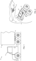
Figs. 1 and3 . However, it is to be understood that the various embodiments as shown and described herein may assume various alternative orientations, except where expressly specified to the contrary. It is also to be understood that the specific devices and processes illustrated in the attached drawings, and described in the following specification are simply exemplary embodiments of the concepts defined in the appended claims. Hence, specific dimensions and other characteristics relating to the embodiments disclosed herein are not to be considered as limiting, unless the claims expressly state otherwise. - The reference numeral 10 (
Fig. 1 ) generally designates a heavy duty tractor and trailer combination, wherein a semi-truck ortractor 12 operationally supports an associatedtrailer 14 via a fifth wheel hitch assembly 16 (Fig. 2 ) and akingpin assembly 18 cooperating therewith. In the illustrated example, the fifthwheel hitch assembly 16 includes a fifthwheel hitch plate 20 pivotally coupled to aframe assembly 22 of the associatedtractor 12 and including a tapered kingpin-receivingthroat 24 and a locking assembly (not shown) as well known in the art. - The kingpin assembly 18 (
Fig. 3 ) is adapted for use within atrailer skid plate 26 mounted to an underside of the associatedtrailer 14. Thetrailer skid plate 26 includes anaperture 28 extending therethrough and that receives thekingpin assembly 18 therein. Thekingpin assembly 18 includes ahousing 30 having a recess in the form of a centrally-locatedaperture 32 extending therethrough, and a plurality of threaded bolt- receivingapertures 34 spaced about theaperture 32. The recess oraperture 32 further includes astep wall 36. Thekingpin assembly 18 further includes a ring-shaped collar member 38 including a centrally-located aperture that defines a cylindrically-shapedfirst portion 40 and an axially arcuately-shapedsecond portion 44 defining a radius r1. The collar member 38 further includes a circumferentially-extending step or groove 46 located along a length of thesecond portion 44 of theaperture 40. The collar member 38 further includes a plurality of bolt-receivingapertures 48 spaced about theaperture 40 and that are co-aligned with theapertures 34 of thehousing 30 when the collar member 38 is coupled with thehousing 30, as described below. - The
kingpin assembly 18 further comprises akingpin 50 that includes anupper head portion 52, alower head portion 54, abody portion 56, and a lock assembly-receivingportion 58. Theupper head portion 52 of thekingpin 50 includes a cylindricalfirst portion 60 and an axially arcuately-shapedsecond portion 62 located between thefirst portion 60 and thebody portion 56. Thesecond portion 62 of theupper head portion 52 defines a radius r2. The lock-assembly receiving portion orneck portion 58 is reduced in size relative to theoverhead portion 54 and thebody portion 56, and is adapted to receive the locking jaws (not shown) of an associated fifth wheel lock assembly thereabout. - In assembly, the
housing 30 is placed above theaperture 28 of thetrailer skid plate 26 and welded thereto about acircumference 66. Thekingpin 50 is placed within the collar member 38 with the collar member 38 being secured to the associatedhousing 30 via a plurality ofbolts 68. It is noted that a seal member in the form of an 0-ring 70 is located within the groove 46, and that awear disk 35 comprising a friction reducing material is located between thefirst position 60 of thekingpin 50, and the collar member 38. It is further noted that the radius r1 of thesecond portion 44 of the collar member 38 and the radius r2 of thesecond portion 62 of theupper head portion 52 of thekingpin 50 are each varying in distance about their respective arcs, and that the radii r1, r2 vary with respect to one another, such that the total area of the mating surfaces of the respective parts are reduced, thereby reducing the associated operational wear. - The
kingpin assembly 18 further includes adirt cover 72 welded within theaperture 32 of thehousing 30, thereby preventing contamination of the pivoting couple between thekingpin 50 and the collar member 38. Alternatively, the dirt cover could be integrally formed with thehousing 30. - In operation, the
kingpin 50 is coupled to the associated fifthwheel hitch assembly 16 when locking jaws of the fifthwheel hitch assembly 16 are received about the lock assembly-receivingportion 58 of thekingpin 50 defined between thelower head portion 54 and thebody portion 56 thereof. As the tow vehicle ortractor 12 turns out of alignment with respect to the towedtrailer 14, thekingpin 50 is allowed to pivot with the components of thetractor 12 and the associated fifthwheel hitch assembly 16 without requiring movement of thehousing 30, the collar member 38, nor any other component of thekingpin assembly 18. - The
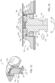
reference numeral 18a (Figs. 4 and 5 ) generally designates an example of a kingpin assembly. Since thekingpin assembly 18a is similar to the previously describedkingpin assembly 18, similar parts appearing inFig. 3 andFigs. 4 and 5 respectively are represented by the same, corresponding reference numeral, except for the suffix "a" in the numerals of the latter. In the illustrated example, thekingpin assembly 18a includes thecollar 38a having a threadedouter surface 100 that threadably engages a threadedportion 102 of thehousing 30a and secures thecollar 38a to thehousing 30a in place of thebolts 68 of the previously described embodiment and within a recess or pocket orbore 104 of thehousing 30a. An upwardly-extendingalignment portion 106 of thekingpin 50a, and analignment receiving portion 108 of the recess or bore 104 of thehousing 30a that receives thealignment portion 106 therein. Thealignment portion 106 includes anaperture 109 extending therethrough, while theportion 108 of thebore 104 includes a circumferentially-extendinggroove 110 aligned with theaperture 109. The assembly further includes a quick-connect assembly 112 comprising a pair ofbearings 114 and a biasingspring member 116. In assembly, the quick-connect assembly allows temporary assembly of thekingpin 50a within thehousing 30a, while allowing the - operator to use both hands to complete the task of permanently securing the
kingpin 50a within thehousing 30a. Specifically, thebearings 114 and thespring member 116 are positioned within thechannel 109, and thekingpin 50a is then placed within thebore 104 of thehousing 30a until thebearings 114 are biased outwardly by thespring 116 and engage thegroove 110 of thehousing 30a. Thecollar member 38a is then positioned about thekingpin 50a and threadably received within thehousing 30a thereby rotatably securing thekingpin 50a within thehousing 30a. - The
kingpin assembly 18a further includes a sensor arrangement 120 (Figs. 5 and 6 ) configured to sense a load exerted on thekingpin 50a. In the illustrated example, thesensor arrangement 120 includes a deflection-type load cell 122 (Fig. 6 ) that includes asensor housing 124 that houses ananalog Hall sensor 126, amagnet 128 separated by a variable distance d, and abiasing spring 129 biasing themagnet 126 away from theHall sensor 128. Thesensor arrangement 120 further includes aplunger arm 130 operably coupled for movement with themagnet 128. Theplunger arm 130 extends through abore 132 that extends through thehousing 30a and into therecess 104 such that theplunger arm 130 abuts theupper head portion 52a of thekingpin 50a. In operation, aforce 134 exerted on thekingpin 50a moves thekingpin 50a relative to thehousing 30a in turn moving theplunger arm 130 in thedirections 136 depending upon the direction of theforce 134. Movement of theplunger arm 130 changes the distance between themagnet 128 and theHall sensor 126. Information gathered from thesensor 126 or plurality ofsensors 126 if employed, may be communicated with acontroller 140 and used to calculate loads exerted on thekingpin 50a. The calculations may be utilized to allow for dynamic control of vehicle braking, vehicle roll, engine and transmission control, and aerodynamic measurements and minimization. - The
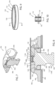
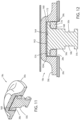
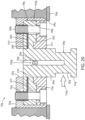
reference numeral 18b (Figs. 7 and 8 ) generally designates the embodiment of the kingpin assembly according to the invention. Since thekingpin assembly 18b is similar to the previously describedkingpin assembly 18a, similar parts appearing inFigs. 4 and 5 andFigs. 7 and 8 respectively are represented by the same, corresponding reference numeral, except for the suffix "b" in the numerals of the latter. Thekingpin assembly 18b is similar in construction and assembly to thekingpin assembly 18a with the most notable exception being the replacement of the sensor arrangement 120a with the sensor arrangement 120b. In the illustrated example, the sensor arrangement 120b includes a capacitive-type load cell 150 that includes acapacitive ring 152 that is positioned between theupper head portion 52b of thekingpin 50b and the recess or bore 104b of thehousing 30b. Thecapacitive ring 152 includes an inner metallic plate orring member 154 and an outer metallic plate orring member 156 that cooperate to house an elastomericdielectric material 158 therebetween. In operation, aforce 134b exerted on thekingpin 50b moves thekingpin 50b relative to thehousing 30b, thereby compressing thering 152 and reducing the distance X between theinner ring 154 and theouter ring 156, thereby changing the capacitance of the elastomericdielectric material 158. Change in the electrical resistance within thedielectric material 158 may then be utilized to calculate the forces exerted on thekingpin 50b. - The
reference numeral 18c (Figs. 11 and 12 ) generally designates another embodiment of the kingpin assembly. Since thekingpin assembly 18c is similar to the previously describedkingpin assembly 18b, similar parts appearing inFigs. 4 and 5 andFigs. 11 and 12 respectively are represented by the same, corresponding reference numeral, except for the suffix "c" in the numerals of the latter. Thekingpin assembly 18c includes a lube plate or bearing 160 positioned between anupper surface 162 and atop wall 164 of thebore 104c. In the illustrated example, thecollar member 38c comprises an integrated custom load cell 166 that includes an outerdeformable housing 168 housing an elastomericdielectric material 170. Theupper head portion 52c of thekingpin 50c is configured such that agap 172 is located therebetween allowing thekingpin 50c to move relative to thehousing 30c, thereby compressing thedielectric material 170 in a manner similar to as discussed above with respect to thesensor arrangement 150. - In yet another example, the kingpin assembly may include a strain gauge load cell 200 (
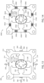
Figs. 13 and 14 ) that includes a first pair of strain gauges including a positive Fy strain gauge 202 and a negative Fy strain gauge 204, and a second pair of strain gauges including a positive Fx strain gauge 206 and a negative Fx strain gauge 208 each coupled to astrain gauge plate 210 positioned within the kingpin assembly. In the illustrated example, thestrain gauge plate 210 includes an outer peripheral body including afirst wall 214, asecond wall 216, athird wall 218 and afourth wall 220 that cooperate with one another to define aninterior space 222. Thestrain gauge plate 210 further includes a plurality of strain members including afirst strain member 224, asecond strain member 226, athird strain member 228 and afourth strain member 230 each extending inwardly from thewalls body portion 232 having an arcuately-shaped, inwardly facinginner face 233, and a relatively narrowedportion 234 positioned between thebody portion 232 and the associatedwall kingpin 50 is positioned between theface 233 of each of thestrain members strain gauge plate 210 exerts acorresponding force strain members force strain members corresponding wall direction wall direction sensors kingpin 50. - The
reference 200d (Fig. 14 ) generally designates another example of the load cell arrangement illustrated inFig. 13 . Since theload cell arrangement 200d is similar to theload cell arrangement 200, similar parts appearing inFig. 13 and Fig. 14 respectively are represented by the same, corresponding reference numeral, except for the suffix "d" in the numerals of the latter. Theload cell arrangement 200d is similar in construction and assembly of theload cell arrangement 200 with the most notable exception being the replacement of the strain gauges 202, 204, 206, 208, withstrain gauges walls - The
reference 18e (Figs. 15 and 16 ) generally designates another example of the kingpin assembly. Since thekingpin assembly 18e is similar to the previously describedkingpin assembly 18a , similar parts appearing inFigs. 4 and 5 and inFigs. 15 and 16 respectively are represented by the same, corresponding reference numeral, except for the suffix "e" in the numerals of the latter. In the illustrated example, thekingpin assembly 18e includes asensor arrangement 120e that includes a plurality of contact force sensors, including a first pair ofsensors 250 and a second pair of contact sensors (not shown) positioned substantially orthogonally offset from the first pair ofcontact sensors 250 about acentral axis 252 of thekingpin 50e. In the illustrated example, each of the contact sensors are positioned between thetop surface 162e of thekingpin 50e and thetop wall 164e of thebore 104e. In operation, aforce 256 exerted on thekingpin 50e in a forward-rearward orlongitudinal direction 257 and/or a left-right orlateral direction 259 results in amoment 258 and aforce 260 being exerted on thecontact sensors 250. These forces as measured by thecontact sensors 250 may then be used to calculate the force is exerted on thekingpin 50e. - The
reference numeral 18f (Figs. 17 and 18 ) generally designates another example of the kingpin assembly. Since thekingpin assembly 18f is similar to the previously describedkingpin assembly 18e, similar parts appearing inFigs. 4 and 5 andFigs 18 and 19 respectively are represented by the same, corresponding reference numeral, except for the suffix "f" in the numerals of the latter. In the illustrated example, thekingpin assembly 18f is similar in construction and assembly to thekingpin assembly 18a with the most notable exception being thesensor arrangement 120f. In the illustrated example, thesensor arrangement 120f (Fig. 19 ) includes a pressure sensor positioned between theupper head portion 52f of thekingpin 50f and of thehousing 30f, and anelastomeric spring 262 positioned between thepressure sensor 260 and theupper head portion 52f of thekingpin 50f and of thehousing 30f. In operation, aforce 134f exerted on thekingpin 50f results in a movement of thekingpin 50f in adirection 264, thereby resulting in aforce 266 being applied to thepressure sensor 260. Information collected from thepressure sensor 260 may then be communicated with thecontroller 140f and used to calculate the forces exerted on thekingpin 50f. - The reference numeral 18g (
Fig. 20 ) generally designates another example of the kingpin assembly. Since the kingpin assembly 18g is similar to previously-describedkingpin assembly 18, similar parts appearing inFig. 3 andFig. 21 respectively are represented by the same, corresponding reference numeral, except for the suffix "g" in the numerals of the latter. In the illustrated example, the kingpin assembly 18g includes acollar 38g and akingpin 50g. Thecollar 38g includes anupper support ring 270 and alower support ring 272. Theupper support ring 270 includes a steppedbore 274 within which the upper head portion 52g of thekingpin 50g is received. Thelower support ring 272 includes a cylindrically-shapedalignment portion 276 that cooperates to rotatably guide thekingpin 50g therewith, as described below. Theupper support ring 270 and thelower support ring 272 each include a plurality of bolt-receiving apertures 48g spaced circumferentially thereabout. Thekingpin 50g includes the upper head portion 52g, thelower head portion 54g, the body portion 56g, and the lockassembly receiving portion 58g. The upper head portion 52g includes a radially outwardly-extendingportion 280 having a downwardly-extending, cylindrically-shapedalignment portion 282 spaced from the body portion 56g. A central bore 283 extends along a length of thekingpin 50g. - In assembly, the upper head portion 52g is received within the
bore 274 of theupper support ring 270, while thealignment portion 276 of thelower support ring 272 and thealignment portion 282 of thekingpin 50g are coupled with one another such that thealignment portion 276 is aligned radially inward from thealignment portion 282 and rotatably guides the same. Awear disk 284 is located with thebore 274 and between the upper head portion 52g of thekingpin 50g and theupper support ring 270. Thekingpin 50g, theupper support ring 270 and thelower support ring 272 are positioned within therecess 104g of thehousing 30g and secured therein by a plurality ofbolts 68g extending through the apertures 48g of theupper support ring 270 and thelower support ring 272, and threadably received within theapertures 34g of thehousing 30g. - The kingpin assembly 18g further includes a
sensor arrangement 120g. In the illustrated example, thesensor arrangement 120g includes a plurality ofstrain gauges 290 positioned within the central bore 283 such that the strain gauges 290 may be utilized to detect deflection of thekingpin 50g when aforce 134g is exerted on thekingpin 50g, thereby allowing calculation of the forces being exerted on thekingpin 50g. - The
reference 18h (Figs. 21 and 22 ) generally designates another example of the present kingpin assembly. Since thekingpin assembly 18h is similar to the kingpin assembly 18g, similar parts appearing inFig. 20 andFigs. 21 and 22 respectively are represented by the same, corresponding reference numeral, except for the suffix "h" in the numerals of the latter. In the illustrated example, the upper head portion 20h of thekingpin 50h is rotatably contained between theupper support ring 270h and thelower support ring 272h. Various examples of the kingpin assembly as previously described herein include varied sensor arrangements, wherein some of the sensor arrangements may need to be calibrated or aligned to a zero position where the kingpin is prevented from rotating with respect to the fifth wheel hitch plate so that the sensors may adequately sense and monitor the true rotation of the kingpin relative to the associated housing, thereby allowing calculation of the forces exerted on the kingpin. In the illustrated example, thekingpin 50h further includes an alignment orflag portion 300 that is configured to be received within and abut the sides of athroat 302 of a fifthwheel hitch plate 304. Although thealignment element 300 as illustrated is provided with a rectangularly-shaped configuration as illustrated, other geometrical configurations may also be utilized. - In one example, the kingpin assembly may also incorporate a
lock sensor 310 configured so as to be able to detect the presence or position of an associated locking arrangement such as a pair oflock jaws 312 and whether thelock jaws 312 are in the correct position so as to secure thekingpin 50h within thethroat 302 of the fifthwheel hitch plate 304. Thelock sensor 310 may include a Hall effect type sensor, inductive proximity sensors or other sensors adequate for sensing the relative position(s) of components of the locking arrangement. - The
kingpin assembly 18h may also include a sensor for detecting the rotation of thekingpin 50h with respect to the associated housing. Wherein therotation sensor 314 may include an absolute rotary encoder, a potentiometer, a Hall effect sensor or other sensor configured to provide such information. - The signals from the
sensors kingpin 50h be positioned at a "zero" position where thealignment element 300 extends rearwardly so as to enable proper alignment and coupling of thekingpin 50h with the fifthwheel hitch plate 304. A return oralignment arrangement 330 is configured to return thekingpin 50h to the "zero" position. In the illustrated example, thereturn arrangement 300 includes arotational deflection spring 332 deflected by a keyway 334 in both directions of rotation of thekingpin 50h. When deflected, thespring 332 exerts a restoring force on the keyway 334 that returns thekingpin 50h to the "zero" position. - The present inventive kingpin assembly allows free rotation of the kingpin by reducing operational wear of the same, allows easy access to and replacement of an associated kingpin subsequent to wear thereof, reduces the amount of maintenance typically required for fifth wheel hitch assemblies, and reduces wear due to debris entering the overall assembly. Further, the present inventive assembly is more durable, allows replacement of certain components thereof by even unskilled personnel, is extremely efficient in use, capable of a long operating life, and particularly well adapted for the proposed use.
- In the foregoing description, it will be readily appreciated by those skilled in the art that modifications may be made to the invention without departing from the concepts disclosed herein. Such modifications are to be considered as included in the following claims, unless these claims by their language expressly state otherwise.
Claims (7)
- A kingpin assembly, comprising:a housing (30) having a recess (32) located therein and configured to be attached to a towed vehicle;a kingpin having at least a portion located within the recess (32) of the housing (30), wherein the kingpin is secured within the recess (32) of the housing (30), and wherein the kingpin includes an axis extending along a length of the kingpin; anda sensor arrangement (120) configured to sense a force exerted on the kingpin in a first direction that is substantially perpendicular to the longitudinal axis,characterized in thatthe sensor arrangement (120) includes a capacitive-type load cell (150) that includes a ring (152) positioned between the kingpin and the housing (30), the ring (152) including an inner electrically conductive ring (154), an outer electrically conductive ring (156) and an elastomeric dielectric material (158) positioned therebetween.
- The kingpin assembly of claim 1, wherein the first direction extends in a substantially longitudinal direction aligned or parallel with a longitudinal axis of the towed vehicle.
- The kingpin assembly of either claim 1 or 2, wherein the sensor arrangement (120) is configured to sense a second force exerted on the kingpin in a second direction that extends perpendicular to the first direction.
- The kingpin assembly of claim 1, wherein the first direction extends in a substantially lateral direction aligned or parallel with a lateral axis of the towed vehicle.
- The kingpin assembly of any one of the preceding claims, wherein the electrically conductive rings (154, 156) are metallic rings (154, 156).
- The kingpin assembly of any one of the preceding claims, wherein the kingpin is rotatably secured within the housing (30).
- The kingpin assembly of either claim 1 or 2, wherein the sensor arrangement (120) is configured to sense a second force exerted on the kingpin in a second direction.
Priority Applications (1)
| Application Number | Priority Date | Filing Date | Title |
|---|---|---|---|
| EP23202686.4A EP4300046A2 (en) | 2018-01-19 | 2019-01-17 | Kingpin assembly with force sensor arrangement |
Applications Claiming Priority (2)
| Application Number | Priority Date | Filing Date | Title |
|---|---|---|---|
| US201862619462P | 2018-01-19 | 2018-01-19 | |
| PCT/IB2019/050410 WO2019142137A2 (en) | 2018-01-19 | 2019-01-17 | Kingpin assembly with rotation sensor arrangement |
Related Child Applications (2)
| Application Number | Title | Priority Date | Filing Date |
|---|---|---|---|
| EP23202686.4A Division EP4300046A2 (en) | 2018-01-19 | 2019-01-17 | Kingpin assembly with force sensor arrangement |
| EP23202686.4A Division-Into EP4300046A2 (en) | 2018-01-19 | 2019-01-17 | Kingpin assembly with force sensor arrangement |
Publications (3)
| Publication Number | Publication Date |
|---|---|
| EP3740418A2 EP3740418A2 (en) | 2020-11-25 |
| EP3740418A4 EP3740418A4 (en) | 2021-06-02 |
| EP3740418B1 true EP3740418B1 (en) | 2023-11-22 |
Family
ID=67298487
Family Applications (2)
| Application Number | Title | Priority Date | Filing Date |
|---|---|---|---|
| EP19741297.6A Active EP3740418B1 (en) | 2018-01-19 | 2019-01-17 | Kingpin assembly with force sensor arrangement |
| EP23202686.4A Pending EP4300046A2 (en) | 2018-01-19 | 2019-01-17 | Kingpin assembly with force sensor arrangement |
Family Applications After (1)
| Application Number | Title | Priority Date | Filing Date |
|---|---|---|---|
| EP23202686.4A Pending EP4300046A2 (en) | 2018-01-19 | 2019-01-17 | Kingpin assembly with force sensor arrangement |
Country Status (3)
| Country | Link |
|---|---|
| US (2) | US11702155B2 (en) |
| EP (2) | EP3740418B1 (en) |
| WO (1) | WO2019142137A2 (en) |
Families Citing this family (8)
| Publication number | Priority date | Publication date | Assignee | Title |
|---|---|---|---|---|
| CA3213679A1 (en) * | 2017-08-25 | 2019-02-25 | Wabash National, L.P. | Composite floor structure with embedded hardpoint connector and method of making the same |
| US11560186B2 (en) * | 2018-04-02 | 2023-01-24 | Morryde International, Inc. | Load sensing pin box |
| AU2018241166B2 (en) * | 2018-05-30 | 2023-05-04 | JPH3 Pty Ltd | Safety apparatus for a fifth wheel coupling |
| US10942271B2 (en) | 2018-10-30 | 2021-03-09 | Tusimple, Inc. | Determining an angle between a tow vehicle and a trailer |
| AU2021203567A1 (en) * | 2020-06-18 | 2022-01-20 | Tusimple, Inc. | Angle and orientation measurements for vehicles with multiple drivable sections |
| US11713076B2 (en) * | 2021-02-01 | 2023-08-01 | Ree Automotive Ltd. | Apparatus for measuring steering angle |
| DE102021109064A1 (en) * | 2021-04-12 | 2022-10-13 | Rühlicke GmbH | Kingpin for a semi-trailer of an articulated motor vehicle |
| DE102022123659B3 (en) * | 2022-09-15 | 2024-03-21 | Trailer Dynamics Gmbh | King pin for a fifth wheel coupling, fifth wheel coupling with king pin and commercial vehicle with this |
Family Cites Families (51)
| Publication number | Priority date | Publication date | Assignee | Title |
|---|---|---|---|---|
| US1593625A (en) * | 1924-06-23 | 1926-07-27 | Taylor Instrument Co | Regulating apparatus |
| US2838324A (en) | 1956-08-09 | 1958-06-10 | West Michigan Steel Foundry Co | Upper fifth wheel with plural adapters for removable king pin |
| GB810903A (en) | 1956-10-15 | 1959-03-25 | Fruehauf Trailer Co | Kingpin assembly for trailers |
| US2958541A (en) | 1958-03-11 | 1960-11-01 | Jost Werke Gmbh | Replaceable kingpin mounting for semitrailer couplings |
| US2907582A (en) | 1958-12-03 | 1959-10-06 | Raymond I Bourke | Anti-jackknifing fifth-wheel for tractor trailer |
| US3520557A (en) | 1967-10-26 | 1970-07-14 | Houdaille Industries Inc | Fifth wheel coupler with rotary damping |
| US3600005A (en) | 1969-12-19 | 1971-08-17 | Dow Chemical Co | Kingpin and support member for a semitrailer rig |
| GB1395003A (en) | 1971-03-01 | 1975-05-21 | Hope Tech Dev Ltd | Locking device for fifth wheel coupling |
| US3807765A (en) | 1972-10-02 | 1974-04-30 | Us Army | Tractor-trailer coupling |
| US3807766A (en) | 1972-12-14 | 1974-04-30 | Us Army | Trailer hitch |
| US3811708A (en) | 1973-02-13 | 1974-05-21 | Us Army | Trailer hitch |
| US3887251A (en) | 1974-08-06 | 1975-06-03 | Roy H Mckay | Tractor and trailer fifth wheel bearing attachment |
| US4106793A (en) | 1977-03-28 | 1978-08-15 | William F. Beebe | Fluid wedged double lock fifth wheel |
| US4254967A (en) | 1979-10-05 | 1981-03-10 | Scanlon Ray M | Removable king pin |
| CH657817A5 (en) | 1982-10-22 | 1986-09-30 | Fischer Ag Georg | DRAWBAR PIN WITH A PLATE FOR A FIFTH FIFTH WHEEL COUPLING. |
| CA2109743A1 (en) | 1993-11-23 | 1995-05-24 | Bertin Poirier | Fifth wheel construction having rotatable bearing plate |
| DE19539998A1 (en) | 1995-10-14 | 1997-04-17 | It Consulting Ag | Semi=trailer fifth wheel coupling pin |
| JP2000512592A (en) | 1996-06-21 | 2000-09-26 | フンガー、ヴァルター | Coupling device for coupling towing vehicle with semi-trailer and method of retrofitting coupling device |
| JPH1120729A (en) * | 1997-07-02 | 1999-01-26 | Toyota Autom Loom Works Ltd | Sensor mounting structure for vehicle |
| US20010028160A1 (en) | 1999-02-26 | 2001-10-11 | Athans George C. | Self-lubricating trailer bearing plate for fifth wheel |
| US6322093B1 (en) | 1999-07-26 | 2001-11-27 | Direct Dimensions Inc. | Double shear trailer bearing plate for fifth wheel |
| US6302424B1 (en) * | 1999-12-09 | 2001-10-16 | Holland Hitch Company | Force-sensing fifth wheel |
| JP4633989B2 (en) | 1999-12-22 | 2011-02-16 | ハンバーガー パテント シュミーダ ゲーエムベーハー | Fifth wheel for traction truck and cargo trailer |
| US6587041B1 (en) * | 2000-04-20 | 2003-07-01 | Wabash Technology Corporation | Semi-tractor fifth wheel sensor and rail car stanchion sensor for a trailer |
| EP1199547A3 (en) * | 2000-10-18 | 2002-07-10 | Diessel Mobile Electronics A/S | Force-sensing fifth wheel |
| NL1018301C2 (en) | 2001-06-15 | 2002-12-17 | Skf Ab | Sensor in King pin. |
| AUPR586101A0 (en) * | 2001-06-21 | 2001-07-12 | Smith Resources International Pty Ltd | Improved combination vehicle with powered trailer |
| US7264259B2 (en) * | 2001-07-05 | 2007-09-04 | Cequent Towing Products, Inc. | Fifth wheel hitch assembly |
| US6530585B1 (en) * | 2001-11-16 | 2003-03-11 | Durrell U Howard | Vehicle steering stabilizer with detent ramp in rotary plate |
| US6565109B1 (en) | 2001-12-14 | 2003-05-20 | Michael Kloepfer | Kingpin assemblies for lightweight trailers |
| CA2392663A1 (en) | 2002-07-12 | 2004-01-12 | Dwayne Hayworth | Pivoting fifth wheel hitch trailer pin assembly |
| US7543831B2 (en) * | 2004-09-01 | 2009-06-09 | Cnh America Llc | Apparatus for installing a sensor on a kingpin |
| US7451995B2 (en) | 2005-09-27 | 2008-11-18 | Martin Marietta Materials, Inc. | King pin assembly for securing trailer to fifth wheel |
| FR2896035B1 (en) * | 2006-01-06 | 2009-01-16 | Moving Magnet Tech | LOW STROKE MAGNETIC POSITION SENSOR, IN PARTICULAR FOR THE TORSION MEASUREMENT OF A STEERING COLUMN |
| US7766361B2 (en) | 2007-10-25 | 2010-08-03 | Saf-Holland, Inc. | Rotating fifth wheel hitch kingpin assembly |
| US8917170B2 (en) * | 2011-10-04 | 2014-12-23 | Santo A. Padula | Apparatus for measuring articulation angle between a tractor and trailer in an articulated vehicle |
| NL2009960C2 (en) | 2012-05-15 | 2013-11-06 | Martinus Theodorus Wetering | TRACTOR-TRAILER COMBINATION. |
| US8960704B2 (en) * | 2013-05-14 | 2015-02-24 | Saf-Holland, Inc. | Fifth wheel hitch kingpin assembly |
| US9016708B2 (en) * | 2013-05-14 | 2015-04-28 | Saf-Holland, Inc. | Fifth wheel hitch kingpin assembly |
| US9302557B2 (en) * | 2013-12-09 | 2016-04-05 | Fontaine Fifth Wheel | Fifth wheel locking mechanism |
| EP3486151A1 (en) * | 2014-01-20 | 2019-05-22 | SAF-Holland, Inc. | Fifth wheel hitch kingpin assembly |
| PL2899101T3 (en) | 2014-01-22 | 2018-10-31 | Helmut Fliegl | King pin with sensor device |
| US10124841B2 (en) * | 2014-03-31 | 2018-11-13 | Jacques Marquis | Kingpin assembly for semitrailer |
| US9470590B2 (en) | 2015-02-12 | 2016-10-18 | Nhk Spring Co., Ltd. | Coil spring modeling apparatus |
| US9723692B2 (en) * | 2015-05-20 | 2017-08-01 | Saf-Holland, Inc | Fifth wheel coupling detection system with inspection and indication lighting arrangement |
| US9550475B1 (en) * | 2015-09-09 | 2017-01-24 | Altec Industries, Inc. | Securely deploying outrigger foot |
| DE102016203224B4 (en) * | 2016-02-29 | 2018-01-25 | Transport Industry Development Centre B.V. | Kingpin device for a trailer steering system |
| US9738125B1 (en) | 2016-05-17 | 2017-08-22 | Horizon Global Americas Inc. | Communication device, system, and method for active control of external vehicle components |
| US11560186B2 (en) * | 2018-04-02 | 2023-01-24 | Morryde International, Inc. | Load sensing pin box |
| US10766531B2 (en) * | 2018-08-31 | 2020-09-08 | Cnh Industrial America Llc | Steering sensor pin assembly |
| DE202020104506U1 (en) * | 2020-08-04 | 2021-11-08 | Dana Italia S.R.L. | Kingpin arrangement |
-
2019
- 2019-01-17 EP EP19741297.6A patent/EP3740418B1/en active Active
- 2019-01-17 US US16/250,643 patent/US11702155B2/en active Active
- 2019-01-17 WO PCT/IB2019/050410 patent/WO2019142137A2/en unknown
- 2019-01-17 EP EP23202686.4A patent/EP4300046A2/en active Pending
-
2023
- 2023-02-27 US US18/174,972 patent/US11912353B2/en active Active
Also Published As
| Publication number | Publication date |
|---|---|
| EP4300046A2 (en) | 2024-01-03 |
| US11912353B2 (en) | 2024-02-27 |
| US20190225286A1 (en) | 2019-07-25 |
| WO2019142137A3 (en) | 2019-10-31 |
| US20230219642A1 (en) | 2023-07-13 |
| EP3740418A2 (en) | 2020-11-25 |
| WO2019142137A2 (en) | 2019-07-25 |
| EP3740418A4 (en) | 2021-06-02 |
| US11702155B2 (en) | 2023-07-18 |
Similar Documents
| Publication | Publication Date | Title |
|---|---|---|
| EP3740418B1 (en) | Kingpin assembly with force sensor arrangement | |
| US6282471B1 (en) | Vehicle roll control | |
| US20080144985A1 (en) | Wheel End With Monitoring Capabilities | |
| EP3287344B1 (en) | Steering assembly with integrated sensor | |
| JP2003530565A (en) | Bearing assembly with sensor for monitoring load | |
| CN108058540A (en) | Wheel connector assembly with the sealing element being connected with adjusting ring interface | |
| US20090010582A1 (en) | Sensor-Incorporated Wheel Support Bearing Assembly | |
| US8075194B2 (en) | Wheel bearing with sensor | |
| US6607203B2 (en) | Steering knuckle | |
| US7097184B2 (en) | Sensor in King-pin | |
| GB2439416A (en) | Fork lift truck with axle load determination for a rear-end axle | |
| WO2008067392A2 (en) | Load sensor and method of sensing a load | |
| GB2275343A (en) | Force measurement in fifth-wheel couplings | |
| US20020089142A1 (en) | Apparatus for sensing an angular position of a wheel of a vehicle about a steering axis | |
| US5438881A (en) | Arrangement of measuring devices on a semitrailer motor vehicle | |
| US20210086557A1 (en) | Wheel speed sensing system | |
| DE102006049494B3 (en) | Wheel suspension for attaching wheel to chassis structure with axle pivot of motor vehicle, has wheel arc and wheel base error sensors which are arranged and fastened on opposite sides of axle pivot | |
| US11531039B2 (en) | Wheel assembly with sensor for measuring wheel movement | |
| ITMI940164A1 (en) | ARRANGEMENT OF MEASURING MEANS IN A TRUCK ARTICULATED VEHICLE | |
| EP1912811A2 (en) | Load sensing wheel support knuckle assembly and method for use | |
| EP2726754B1 (en) | Brake caliper for a foundation brake of an automotive vehicle, brake actuator and foundation brake comprising such a brake caliper and such an actuator | |
| US20190366786A1 (en) | Measuring device for measuring an articulation angle and vehicle combination | |
| DE10333284B4 (en) | Monitoring the axial load acting on the hub of a motor vehicle wheel | |
| US9976872B2 (en) | Rotational angle sensor | |
| WO2003011676A1 (en) | Vehicle corner module and assembly comprising such module |
Legal Events
| Date | Code | Title | Description |
|---|---|---|---|
| STAA | Information on the status of an ep patent application or granted ep patent |
Free format text: STATUS: THE INTERNATIONAL PUBLICATION HAS BEEN MADE |
|
| PUAI | Public reference made under article 153(3) epc to a published international application that has entered the european phase |
Free format text: ORIGINAL CODE: 0009012 |
|
| STAA | Information on the status of an ep patent application or granted ep patent |
Free format text: STATUS: REQUEST FOR EXAMINATION WAS MADE |
|
| 17P | Request for examination filed |
Effective date: 20200807 |
|
| AK | Designated contracting states |
Kind code of ref document: A2 Designated state(s): AL AT BE BG CH CY CZ DE DK EE ES FI FR GB GR HR HU IE IS IT LI LT LU LV MC MK MT NL NO PL PT RO RS SE SI SK SM TR |
|
| AX | Request for extension of the european patent |
Extension state: BA ME |
|
| RIC1 | Information provided on ipc code assigned before grant |
Ipc: B62D 7/18 20060101ALI20210125BHEP Ipc: G01D 5/14 20060101ALI20210125BHEP Ipc: B62D 15/02 20060101AFI20210125BHEP |
|
| DAV | Request for validation of the european patent (deleted) | ||
| DAX | Request for extension of the european patent (deleted) | ||
| A4 | Supplementary search report drawn up and despatched |
Effective date: 20210430 |
|
| RIC1 | Information provided on ipc code assigned before grant |
Ipc: B62D 15/02 20060101AFI20210423BHEP Ipc: B62D 7/18 20060101ALI20210423BHEP Ipc: G01D 5/14 20060101ALI20210423BHEP |
|
| STAA | Information on the status of an ep patent application or granted ep patent |
Free format text: STATUS: EXAMINATION IS IN PROGRESS |
|
| 17Q | First examination report despatched |
Effective date: 20220217 |
|
| GRAP | Despatch of communication of intention to grant a patent |
Free format text: ORIGINAL CODE: EPIDOSNIGR1 |
|
| STAA | Information on the status of an ep patent application or granted ep patent |
Free format text: STATUS: GRANT OF PATENT IS INTENDED |
|
| INTG | Intention to grant announced |
Effective date: 20230621 |
|
| GRAS | Grant fee paid |
Free format text: ORIGINAL CODE: EPIDOSNIGR3 |
|
| GRAA | (expected) grant |
Free format text: ORIGINAL CODE: 0009210 |
|
| STAA | Information on the status of an ep patent application or granted ep patent |
Free format text: STATUS: THE PATENT HAS BEEN GRANTED |
|
| AK | Designated contracting states |
Kind code of ref document: B1 Designated state(s): AL AT BE BG CH CY CZ DE DK EE ES FI FR GB GR HR HU IE IS IT LI LT LU LV MC MK MT NL NO PL PT RO RS SE SI SK SM TR |
|
| P01 | Opt-out of the competence of the unified patent court (upc) registered |
Effective date: 20231018 |
|
| REG | Reference to a national code |
Ref country code: GB Ref legal event code: FG4D |
|
| REG | Reference to a national code |
Ref country code: CH Ref legal event code: EP |
|
| REG | Reference to a national code |
Ref country code: DE Ref legal event code: R096 Ref document number: 602019041896 Country of ref document: DE |
|
| REG | Reference to a national code |
Ref country code: IE Ref legal event code: FG4D |
|
| REG | Reference to a national code |
Ref country code: SE Ref legal event code: TRGR |
|
| REG | Reference to a national code |
Ref country code: LT Ref legal event code: MG9D |
|
| REG | Reference to a national code |
Ref country code: NL Ref legal event code: MP Effective date: 20231122 |
|
| PG25 | Lapsed in a contracting state [announced via postgrant information from national office to epo] |
Ref country code: GR Free format text: LAPSE BECAUSE OF FAILURE TO SUBMIT A TRANSLATION OF THE DESCRIPTION OR TO PAY THE FEE WITHIN THE PRESCRIBED TIME-LIMIT Effective date: 20240223 |
|
| PG25 | Lapsed in a contracting state [announced via postgrant information from national office to epo] |
Ref country code: IS Free format text: LAPSE BECAUSE OF FAILURE TO SUBMIT A TRANSLATION OF THE DESCRIPTION OR TO PAY THE FEE WITHIN THE PRESCRIBED TIME-LIMIT Effective date: 20240322 |
|
| PG25 | Lapsed in a contracting state [announced via postgrant information from national office to epo] |
Ref country code: LT Free format text: LAPSE BECAUSE OF FAILURE TO SUBMIT A TRANSLATION OF THE DESCRIPTION OR TO PAY THE FEE WITHIN THE PRESCRIBED TIME-LIMIT Effective date: 20231122 |
|
| REG | Reference to a national code |
Ref country code: AT Ref legal event code: MK05 Ref document number: 1633584 Country of ref document: AT Kind code of ref document: T Effective date: 20231122 |
|
| PG25 | Lapsed in a contracting state [announced via postgrant information from national office to epo] |
Ref country code: NL Free format text: LAPSE BECAUSE OF FAILURE TO SUBMIT A TRANSLATION OF THE DESCRIPTION OR TO PAY THE FEE WITHIN THE PRESCRIBED TIME-LIMIT Effective date: 20231122 |
|
| PG25 | Lapsed in a contracting state [announced via postgrant information from national office to epo] |
Ref country code: AT Free format text: LAPSE BECAUSE OF FAILURE TO SUBMIT A TRANSLATION OF THE DESCRIPTION OR TO PAY THE FEE WITHIN THE PRESCRIBED TIME-LIMIT Effective date: 20231122 |