EP3739758A2 - Dispositif capteur intelligent - Google Patents
Dispositif capteur intelligent Download PDFInfo
- Publication number
- EP3739758A2 EP3739758A2 EP20174054.5A EP20174054A EP3739758A2 EP 3739758 A2 EP3739758 A2 EP 3739758A2 EP 20174054 A EP20174054 A EP 20174054A EP 3739758 A2 EP3739758 A2 EP 3739758A2
- Authority
- EP
- European Patent Office
- Prior art keywords
- sensor
- signal
- actuation
- deformation
- operating body
- Prior art date
- Legal status (The legal status is an assumption and is not a legal conclusion. Google has not performed a legal analysis and makes no representation as to the accuracy of the status listed.)
- Pending
Links
Images


Classifications
-
- H—ELECTRICITY
- H03—ELECTRONIC CIRCUITRY
- H03K—PULSE TECHNIQUE
- H03K17/00—Electronic switching or gating, i.e. not by contact-making and –breaking
- H03K17/94—Electronic switching or gating, i.e. not by contact-making and –breaking characterised by the way in which the control signals are generated
- H03K17/96—Touch switches
- H03K17/9618—Touch switches using a plurality of detectors, e.g. keyboard
-
- H—ELECTRICITY
- H03—ELECTRONIC CIRCUITRY
- H03K—PULSE TECHNIQUE
- H03K17/00—Electronic switching or gating, i.e. not by contact-making and –breaking
- H03K17/94—Electronic switching or gating, i.e. not by contact-making and –breaking characterised by the way in which the control signals are generated
- H03K17/965—Switches controlled by moving an element forming part of the switch
- H03K17/97—Switches controlled by moving an element forming part of the switch using a magnetic movable element
- H03K17/972—Switches controlled by moving an element forming part of the switch using a magnetic movable element having a plurality of control members, e.g. keyboard
-
- H—ELECTRICITY
- H03—ELECTRONIC CIRCUITRY
- H03K—PULSE TECHNIQUE
- H03K17/00—Electronic switching or gating, i.e. not by contact-making and –breaking
- H03K17/94—Electronic switching or gating, i.e. not by contact-making and –breaking characterised by the way in which the control signals are generated
- H03K17/965—Switches controlled by moving an element forming part of the switch
- H03K17/97—Switches controlled by moving an element forming part of the switch using a magnetic movable element
- H03K2017/9706—Inductive element
-
- H—ELECTRICITY
- H03—ELECTRONIC CIRCUITRY
- H03K—PULSE TECHNIQUE
- H03K2217/00—Indexing scheme related to electronic switching or gating, i.e. not by contact-making or -breaking covered by H03K17/00
- H03K2217/94—Indexing scheme related to electronic switching or gating, i.e. not by contact-making or -breaking covered by H03K17/00 characterised by the way in which the control signal is generated
- H03K2217/96—Touch switches
- H03K2217/96038—Inductive touch switches
Definitions
- the invention relates to a method for operating a sensor device for actuation by deformation of an operating body, a computer program product, a sensor device for actuation by deformation of an operating body and a vehicle.
- Touch and / or pressure-sensitive sensors and proximity sensors in vehicles are known from the prior art.
- the pressure-sensitive sensors are mostly accessible from the outside or are connected to an actuating element which can be moved in order to trigger the pressure sensor.
- vehicle functions are often activated. For example, an electronic lock can be activated.
- the disadvantage here is that the tactile and / or pressure-sensitive sensors normally require a breakthrough in an outer surface, which can entail structural restrictions and design disadvantages. Therefore it is, for example, from the DE 10 2016 122 550 A1 known to arrange a sensor behind a vehicle panel and to detect the deformation of the vehicle panel. As a result, the sensor can be mounted on a vehicle panel independently of the vehicle outer surface, its actuation function being retained in that the sensor detects, in particular, elastic deformations of the panel when a user presses on the panel from outside.
- external influences such as temperature changes, can lead to deformation of the sheet metal, which can then promote false triggering or incorrect detection of the sensor.
- the first and second sensor signals can be measurement signals from (a first and second) sensor elements of a sensor device. Ideally, each sensor element has its own sensor signal. More than two sensor elements can also be provided in the sensor device. It is also conceivable that the measurement signals of the sensor elements are at least partially evaluated when generating the sensor signals.
- the operating body can e.g. comprise a moving part of a vehicle. The operating body can preferably be a vehicle panel.
- the first and second sensor signals can be generated inductively, e.g. Sensor elements assigned to the sensor signals have a coil in order to enable the inductive measurement when a magnetizable and / or electrically conductive body approaches the sensor elements due to the deformation.
- a metal plate or a metallic coating is applied, in particular glued, to the operating body in the area of the sensor elements in order to cause a deflection of the metal body (also in the form of a metallic coating) as a result of a deformation of the operating body which can be detected by the sensor elements.
- the reference can preferably be understood as a reference signal or a reference value.
- the specific direction of deviation of the respective sensor signal can include a direction of a signal amplitude of the respective sensor signal.
- the direction of deviation can include a completely different course of the first and / or second sensor signal if, for example, due to the deformation, the first and / or second sensor signal moves away from the reference.
- Specific can in particular be understood to mean that the direction of deviation is predetermined or can be learned in order to recognize the deformation and / or actuation.
- an image of the specific direction of deviation can be specified, which reflects a typical deformation state.
- the detection of the actuation as a function of the directions of deviation can thus include an evaluation of the directions of deviation and / or the sensor signals.
- the direction of deviation can be used to distinguish whether the deformation is a positive or a negative deflection of the operating body. It can thus be predetermined, for example, that an actuation function is triggered when, on the one hand, a deformation is detected and, on the other hand, this is recognized as pressure on the operating body.
- a signal image can be specified via the specific direction of deviation of the first and second sensor signals, which represents a characteristic for a conscious (intentional) deformation of the operating body for triggering an actuation.
- the directions of deviation of the first and second sensor signals indicate a pressure state of the operating body, and their respective signal amplitudes have the same deflection. This makes it possible to determine with a high degree of accuracy that the deformation has taken place or is taking place between the sensor elements and thus e.g. is recognized for actuation.
- the deformation can preferably be localized as a function of the specific directions of deviation of the first and second sensor signals.
- a position of the deformation can be recognized on the basis of the specific deviation directions of the first and second sensor signals.
- the operating body is in a compressive stress state in the area of the first sensor element and in a tensile stress state in the area of the second sensor element, the compressive stress state being assigned a deflection of the Operating body leads in the direction of the sensor elements and the tensile stress state leads to a deflection of the operating body counter to the direction of the sensor elements.
- different actuation requests can be detected by the first and second sensor signals depending on the printing position and / or can be distinguished from incorrect actuations.
- At least one signal amplitude of the first and second sensor signals is taken into account when the actuation is recognized.
- the signal amplitude can in particular be a deviation from the reference.
- a strength of the deflection can thus also be identified and thus assigned to an intended or unintentional actuation. Because this is taken into account for the first and second sensor signals, the accuracy of the localization of the deformation can also be improved.
- a complete signal image of the sensor signals can be specified, which represents a characteristic of an intended actuation action. It can be provided that the deformation is only recognized as an intended actuation action when the sensor signals reflect the specified signal image.
- a mean value of a measurement signal is preferably formed.
- the sensor signals can thus include processed measurement signals.
- the averaging can reduce further disturbance variables in the sensor signals and thus improve the detection of the deformation.
- the mean value can comprise an arithmetic mean and / or a median.
- a signal strength, a signal frequency and / or the like can be used to form the mean value.
- further signal fluctuations of a measurement signal can thus be compensated for and processed into a sensor signal which is easier to evaluate with regard to the deformation.
- At least one reference limit value is specified from which the adaptation of the reference is interrupted, in particular so that a signal amplitude is detected based on the reference limit value. It can thus be provided that the adjustment of the reference up to a predetermined value, i. the reference limit value.
- the reference limit value can e.g. be predetermined on the basis of usual temperature fluctuations and the resulting deformation of the operating body.
- the reference limit value can create a simple possibility of realizing a reference value tracking and being able to recognize an actuation.
- the reference limit value is time-dependent. As a result, e.g. Slowly changing deformations can be distinguished from fast deformations.
- a trigger parameter can preferably be specified for a method according to the invention and the actuation signal can be output if the trigger parameter is achieved by at least one of the sensor signals or all sensor signals, in particular at least one of the signal amplitudes of the sensor signals.
- the triggering parameter can provide a triggering criterion that relates to the signal amplitude of the first and / or second sensor signal.
- a deactivation parameter can be specified and the outputting of the actuation signal can be stopped if the deactivation parameter is reached by at least one of the sensor signals, in particular at least one of the signal amplitudes of the sensor signals, while the actuation signal is being output. Stopping the actuation signal can be understood to mean that the actuation signal is completely suspended or has a signal profile which signals non-actuation.
- the deactivation parameter can preferably be adapted with the reference.
- the deactivation parameter can form a threshold value opposite to the direction of deviation of the sensor signals, from which a stop of the actuation action is recognized.
- an upper threshold value from which the actuation action is triggered and if the sensor signal falls below the deactivation parameter can be recognized as a stop of the actuation can be given by the trigger parameter.
- a reference value tracking can thus also be transferred to the triggering parameter and / or deactivation parameter, so that the actuation can be recognized in a simple manner as a function of the reference value tracking.
- external influences on the deformation state of the operating body can be taken into account and lead to improved accuracy or a reduction in incorrect actuations.
- a trigger parameter and / or a deactivation parameter can preferably be specified and / or adapted for each of the deviation directions.
- a computer program product comprises commands which, when the commands and / or the program are executed by a control unit, cause the control unit to carry out a method according to the invention.
- the method can thus be carried out in particular by executing the commands or the program by the control unit.
- the computer program product can be written as instruction code in a programming language, e.g. Java, C ++ or the like can be implemented.
- the control unit can be a computer unit, a microprocessor and / or the like.
- the instruction code can program the control unit in such a way that the desired functions are carried out.
- the computer program product can be in a network, e.g. the Internet or a local area network, provided and / or downloadable.
- the computer program product can be implemented by one or more electronic circuits in hardware or in any hybrid form, i.e. can be or can be implemented by means of software components and hardware components.
- a sensor device for actuation by deformation of an operating body.
- the sensor device has at least a first and a second sensor element, which can each be arranged at a distance from the operating body in order to detect a deformation of the operating body.
- the sensor device also has a control unit for evaluating a first sensor signal from the first sensor element as a result of the deformation and a second sensor signal from the second sensor element as a result of the deformation.
- the control unit has a recognition module for recognizing the actuation as a function of at least one specific direction of deviation of the first and second sensor signals from a reference.
- the sensor signals can relate to a mean value, in particular of signal amplitudes, of the first and / or second sensor element.
- the reference can also be related to a mean value.
- the detection module can be designed to localize the deformation in relation to the first and second sensor elements.
- the specific direction of deviation can include a positive and / or negative direction of the sensor signal, in particular a signal amplitude of the sensor signal.
- the first and second sensor elements can preferably have the same distance from the operating body and / or can be arranged together on the operating body as a structural unit.
- a sensor device according to the invention thus brings the same advantages as have already been described in detail with reference to a method according to the invention have been.
- the control unit in particular the detection module, is designed to carry out a method according to the invention.
- the first and second sensor elements can preferably be connected to a fastening element by means of which the first and second sensor element can be fastened to the operating body.
- the sensor device can have at least one connection line for connecting the first or second sensor element to electronics.
- the connection line can be fastened separately to the fastening element on the operating body or a further component.
- the fastening element which connects the first and second sensor elements can thus create a structural unit by means of which the first and second sensor elements can be arranged in a simple manner at a defined distance from one another and / or from the operating body on the operating body.
- the fastening element can ensure that the sensor elements are also coupled to one another during operation, i.e. e.g. can follow this movement at the same time when the operating body moves.
- the fastening element has at least two fastening sections, between which the first and second sensor elements are arranged.
- the fastening sections can in particular be connected to one another.
- the fastening sections can preferably form an annular fastening area.
- the first and second sensor elements can be arranged within the annular fastening area.
- the at least two fastening sections between which the first and second sensor elements are arranged can distinguish a symmetrical force outside the sensor elements and in particular outside the fastening sections from a central actuating force.
- control unit has a sensor board which is connected to the sensor elements and / or the fastening element to form an assembly that can be mounted on the operating body. Electronics for evaluation can thus be physically connected to the first and second sensor elements and form the assembly. This simplifies the assembly of the sensor device on the operating body and simplifies the handling during the production of the sensor device.
- a third sensor element can be provided in a sensor device according to the invention, which can be arranged at a distance from the operating body to detect the deformation of the operating body, a specific direction of deviation of a third sensor signal, which can be assigned to the third sensor signal, as a result of the deformation by the detection module during detection the actuation can be taken into account.
- the sensor device has only three sensor elements.
- the third sensor element can improve detection, in particular localization, of the deformation.
- the three sensor elements can preferably be arranged in a row next to one another. As a result, an average actuation of the sensor device can be identified particularly precisely. In addition, it can be realized that several actuation positions can be recognized.
- the sensor device can, with its existing sensor elements, form a keyboard, in particular (10-digit) numeric keyboard or letter keyboard, the number of existing sensor elements preferably being less (and indeed significantly less) than the number of existing keys.
- a 10-key keyboard with 10 keys can be formed, since the deformation / determination of the pressure point of the actuation is precisely localized by evaluating the sensor signals from the sensor elements present.
- the first sensor element is arranged centrally between the fastening sections and / or between the second and third sensor elements.
- an actuation can be recognized with high accuracy in the area of the first sensor element.
- three sensor elements can be arranged in a row to one another.
- the sensor elements are inductive sensor elements, in particular in the form of LDC sensor elements.
- the sensor elements can preferably include LDC coils, by means of which inductive detection of the deformation is made possible.
- the sensor elements can act with a metallic body that is magnetizable and / or electrically conductive. This can be realized by the operating body itself or an auxiliary body which is arranged on the operating body.
- the auxiliary body can e.g. comprise a metallic plate.
- the control unit has a filter module for removing unwanted signal interference, in particular in the form of signal peaks, of the first and / or second and / or third sensor signal.
- the control unit or the filter module can thus be designed to debounce the sensor signals, so that signal peaks can be distinguished from actual actuation actions. Thus, the accuracy in recognizing the actuation can be improved.
- control unit has a compensation module for adapting the reference to a deformation state of the operating body, in particular during operation of the sensor device.
- the reference can thus be adapted as a function of a temperature change and / or of static voltage states of the operating body, so that these influences can be excluded from the evaluation of the sensor signals.
- the accuracy in recognizing the actuation is improved, it being possible in particular to differentiate between wanted (conscious) and unwanted (accidental) deformations.
- the control unit has an output module for outputting an actuation signal for controlling an electrical function, in particular wherein the actuation signal is a Has actuation amplitude, the direction of which is independent of the reference and / or the directions of deviation of the sensor signals.
- the electrical function can thus be triggered by the sensor device as a function of the detection of the actuation. In particular, it can be triggered directly by the control unit of the sensor device. As a result of the independence of the actuation signal from the reference, the evaluation of the sensor signals can thus be shifted to the sensor device and not be left to a further control unit.
- the control unit has a memory module for specifying a triggering parameter, the actuation signal being output if the triggering parameter is achieved by at least one of the sensor signals or all of the sensor signals, in particular a sensor signal amplitude of the sensor signals.
- the control unit has a memory module for specifying a deactivation parameter, the outputting of the actuation signal by the output module can be interrupted if the deactivation parameter during the outputting of the actuation signal by at least one of the sensor signals or all sensor signals, in particular one Sensor signal amplitude of the sensor signals is achieved.
- the storage module can be used to specify the deactivation parameter in a simple manner.
- the deactivation parameter can be preset at the factory or can be learned, so that the deactivation parameter can be changed in the memory module.
- the deactivation parameter can thus represent a holding threshold for the actuation.
- the compensation module is preferably designed to adapt the triggering parameter and / or the deactivation parameter as a function of the reference.
- the reference value tracking can thus also be transferred to the trigger parameter and the deactivation parameter so that these threshold values are also tracked. This results in an advantageous evaluation of the sensor signals, which enables precise detection of the deformation or the actuation request.
- a vehicle having a deformable operating body and a sensor device according to the invention is claimed.
- a vehicle according to the invention thus has the same advantages as have already been described in detail with reference to a method according to the invention and / or a sensor device according to the invention.
- the vehicle is a motor vehicle.
- the deformable operating body can preferably be a movable part, e.g. act in the form of a door and / or tailgate of the vehicle.
- Figure 1 shows a sensor device 10 according to the invention for detecting 106 an actuation on an operating body 2.
- the operating body 2 can preferably be a movable part of a vehicle 1. So is in Figure 3 a vehicle 1 according to the invention with the sensor device 10 is shown, the operating body 2 being in the form of a tailgate of the vehicle 1. However, it is also conceivable that the operating body 2 is designed as part of a vehicle door, tank lid, glove compartment or the like.
- the functional unit 3 can be, for example, a lock of the movable part, an authentication unit for authenticating the user or some other vehicle function.
- the sensor device 10 To recognize 106 the actuation as a function of the deformation, the sensor device 10, as in FIG Figures 1 and 2 shown, a first and a second sensor element 11, 12, which are each arranged at a distance from the operating body 2 for detecting a deformation of the operating body 2.
- the sensor device 10 advantageously has a third sensor element 13, which is also arranged at a distance from the operating body 2 in order to detect the deformation of the operating body 2.
- the sensor elements 11, 12, 13 are preferably LDC sensor elements, in particular in the form of LDC coils.
- the sensor elements 11, 12, 13 are connected by a fastening element 14 and arranged in a row to one another.
- the fastening element 14, with which the sensor elements 11, 12, 13 are fastened to the operating body 2 has two fastening sections 14.1, between which the sensor elements 11, 12, 13 are arranged.
- the at least two fastening sections 14.1 are connected to one another in a ring shape, so that an annular fastening surface for fastening the sensor device 10 to the operating body 2 results.
- This fastening option has the advantage that a deformation as a result of an actuating force F can be distinguished from a second deformation as a result of a symmetrical actuation force F outside the fastening element 14.
- This is for example in the Figures 4a and 4b shown. So shows Figure 4a a central actuating force F which acts in the area of the first sensor element 11 and which Figure 4b a symmetrical actuation force F, which acts outside the fastened area of the sensor device 10.
- the arrangement of the sensor elements 11, 12, 13 between the fastening sections 14.1 thus results in a distinguishable deformation of the operating body 2, which can be detected by the sensor device 10 and, in particular, can be evaluated for detecting 106 the actuation.
- the sensor device 10 as in FIG Figure 3 shown, a control unit 20 for evaluating sensor signals 11.1, 12.1, 13.1 of the sensor elements 11, 12, 13.
- the control unit 20 is preferably designed as a sensor control unit and can, for example, detect a processor and / or a microcontroller.
- the control unit 20 can be provided at least partially on a sensor board in order to enable a sensor-related evaluation of the sensor signals 11.1, 12.1, 13.1.
- the control unit 20 is integrated into a central control device of the vehicle 1.
- the sensor device 10 can have a control line 16, which can preferably also be attached to the operating body 2.
- the control unit 20 has a recognition module 21 for recognizing 106 the actuation based on the deformation as a function of specific directions 200.1, 200.2 of the sensor signals 11.1, 12.1, 13.1 from a reference 200.
- the control unit 20 provides a method 100 according to the invention for actuation by the deformation of the operating body 2 and / or a computer program product 300 according to the invention Figure 8 executable.
- Figure 8 shows the method 100 according to the invention for carrying out the method steps described below in a schematic representation. Furthermore, the computer program 300 is shown, which comprises commands 301 which, when the commands 301 are executed by the control unit 20, cause the control unit 20 to carry out the method 100.
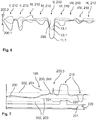
- Figure 6 shows the course of the sensor signals 11.1, 12.1, 13.1 and the specific directions of deviation 200.1, 200.2.
- the sensor signals 11.1, 12.1, 13.1 each run differently in relation to different positions I to IX on the operating body 2.
- Positions I to IX on the control body 2 are in Figure 5 shown, preferably wherein the sensor elements 11, 12, 13 are arranged at the positions IV to VI or at the position V behind the operating body 2. Pressing the respective positions I to IX on the operating body 2 leads to different deformations of the operating body 2, which are mapped by the specific deviation directions 200.1, 200.2 of the sensor signals 11.1, 12.1, 13.1.
- the in Figure 6 The course shown is to be understood only schematically and may differ for positions I to IX.
- an actuation force F generates different signal amplitudes 210 of the sensor signals 11.1, 12.1, 13.1 of the three sensor elements 11, 12, 13 on one of the positions I to IX on the operating body 2.
- the directions of deviation 200.1, 200.2 relate refers to a reference 200, from which the signal amplitudes 210 proceed.
- an actuation force at position I of the operating body 2 leads to a compressive stress state or a negative deformation in the area of the first and second sensor elements 11, 12 and thus to a negative direction of deviation 200.1 of the sensor signals 11.1, 12.1, but at the same time to a tensile stress state in the area of the third sensor element 13 and thus to a positive deformation, which in turn leads to a specific deviation direction 200.2 in the positive direction.
- a specific image of the sensor signals 11.1, 12.1, 13.1 can be present for each of the positions I to IX and thus the deformation can be localized and the actuation can be recognized as a function of the localization.
- the detection 106 of the actuation of the sensor device 10 is provided for the case that the actuation force F is localized at the central position V, ie in the center of the sensor device 10. This can be recognized, for example, from the fact that all specific deviation directions 200.1 are negative.
- the sensor signals 11.1, 12.1, 13.1 are generated 101, 102, 103 in particular for each of the sensor elements 11, 12, 13 separately and / or simultaneously.
- the sensor signals 11.1, 12.1, 13.1 can preferably be processed measurement signals, wherein in particular a mean value can be formed in each case in order to generate the sensor signals 11.1, 12.1, 13.1.
- Figure 7 also shows, by way of example, using a single sensor signal 11.1, how this can be advantageously interpreted in order to avoid false triggering.
- removal 104 of undesired signal interference 200.3 is provided.
- the control unit 20 can have a filter module 22 for removing 104 undesired signal interference 200.3.
- an adaptation 105 of the reference 200 to the deformation state of the operating body 2, in particular by a compensation module 23 of the control unit 20, is provided while the sensor signal 11.1 is being generated.
- a reference limit value 201 is specified, from which the adaptation 105 of the reference 200 is interrupted, so that the signal amplitude 210 of the sensor signal 11.1 is detected based on the reference limit value 201 in order to detect the deformation.
- the reference limit value 201 can be an absolute value or a time-dependent parameter.
- a deactivation parameter 203 and a triggering parameter 202 are also specified, in particular by a memory module 25 of the control unit 20, and are also carried along when the reference 200 is adjusted 105. This results in a recalibration during operation of the sensor device 10, in which the criteria for the actuation or non-actuation of the sensor device 10 are shifted and adapted to the current state of deformation of the operating body 2.
- the triggering parameter 202 is provided so that an output 107 of an actuation signal 220 is started by an output module 24 of the control unit 20.
- the trigger parameter 202 and the deactivation parameter 203 can be identical.
- the actuation signal 220 can be used to control the electrical function of the functional unit 3 of the motor vehicle 1, the actuation signal 220 having an actuation amplitude 221, the direction of which is independent of the reference 200.
- an unambiguous actuation signal 220 can be output which can accordingly be interpreted in a simple manner by the functional unit 3 and / or a subsequent control unit. If the deactivation parameter 203 is reached by the respective signal amplitude 210 after the triggering, the output 107 of the actuation signal 220 is stopped.
- the actuation signal 220 can be completely suspended or signal non-actuation.
Applications Claiming Priority (1)
| Application Number | Priority Date | Filing Date | Title |
|---|---|---|---|
| DE102019113096.4A DE102019113096A1 (de) | 2019-05-17 | 2019-05-17 | Intelligente Sensorvorrichtung |
Publications (2)
| Publication Number | Publication Date |
|---|---|
| EP3739758A2 true EP3739758A2 (fr) | 2020-11-18 |
| EP3739758A3 EP3739758A3 (fr) | 2021-03-17 |
Family
ID=70977319
Family Applications (1)
| Application Number | Title | Priority Date | Filing Date |
|---|---|---|---|
| EP20174054.5A Pending EP3739758A3 (fr) | 2019-05-17 | 2020-05-12 | Dispositif capteur intelligent |
Country Status (2)
| Country | Link |
|---|---|
| EP (1) | EP3739758A3 (fr) |
| DE (1) | DE102019113096A1 (fr) |
Citations (1)
| Publication number | Priority date | Publication date | Assignee | Title |
|---|---|---|---|---|
| DE102016122550A1 (de) | 2016-11-16 | 2018-05-17 | Huf Hülsbeck & Fürst Gmbh & Co. Kg | Sensorsystem zur Aktivierung wenigstens einer Fahrzeugfunktion |
Family Cites Families (2)
| Publication number | Priority date | Publication date | Assignee | Title |
|---|---|---|---|---|
| US8040142B1 (en) * | 2006-03-31 | 2011-10-18 | Cypress Semiconductor Corporation | Touch detection techniques for capacitive touch sense systems |
| WO2008071196A2 (fr) * | 2006-12-15 | 2008-06-19 | Bang & Olufsen A/S | Dispositif tactile |
-
2019
- 2019-05-17 DE DE102019113096.4A patent/DE102019113096A1/de active Pending
-
2020
- 2020-05-12 EP EP20174054.5A patent/EP3739758A3/fr active Pending
Patent Citations (1)
| Publication number | Priority date | Publication date | Assignee | Title |
|---|---|---|---|---|
| DE102016122550A1 (de) | 2016-11-16 | 2018-05-17 | Huf Hülsbeck & Fürst Gmbh & Co. Kg | Sensorsystem zur Aktivierung wenigstens einer Fahrzeugfunktion |
Also Published As
| Publication number | Publication date |
|---|---|
| EP3739758A3 (fr) | 2021-03-17 |
| DE102019113096A1 (de) | 2020-11-19 |
Similar Documents
| Publication | Publication Date | Title |
|---|---|---|
| EP1910631B1 (fr) | Dispositif de detecteur pour systeme de fermeture d'un vehicule automobile, et procede associe | |
| DE10221511B4 (de) | Schlüssellose Sicherheits-/Betätigungseinrichtung für Kraftfahrzeuge | |
| EP1238177B1 (fr) | Dispositif de poignee exterieure de porte | |
| EP2753485B1 (fr) | Système de commande | |
| EP3451301A1 (fr) | Système d'accès pour un véhicule | |
| WO2018091199A1 (fr) | Système de détection destiné à l'activation d'au moins une fonction de véhicule | |
| EP3036833B1 (fr) | Système d'actionnement sans contact d'une porte de véhicule | |
| EP3191665A1 (fr) | Système de poignée de porte d'un véhicule automobile | |
| EP1450489B1 (fr) | Générateur d'un signal de déclenchement | |
| EP4258312A2 (fr) | Mécanisme de déverrouillage de porte et/ou d'ouverture de porte doté d'un dispositif d'actionnement | |
| EP3739757B1 (fr) | Dispositif capteur optimisé | |
| EP3461697A1 (fr) | Système et procédé de détection d'un traitement d'activation | |
| EP3739758A2 (fr) | Dispositif capteur intelligent | |
| WO2010089206A1 (fr) | Capteur tactile capacitif | |
| DE102018120561B4 (de) | Multifunktionales Bedienelement für ein Kraftfahrzeug | |
| EP4181397A1 (fr) | Module de poignée doté d'un module d'actionnement pour un système de fermeture électronique et porte de véhicule dotée d'un module de poignée | |
| DE102018010324B4 (de) | Multifunktionales Bedienelement für ein Kraftfahrzeug | |
| EP4286630A1 (fr) | Module d'actionnement pour un système de fermeture électronique et composant de véhicule | |
| DE102023205184A1 (de) | Fahrzeugzugangsanordnung und Fahrzeugelement mit einer solchen Fahrzeugzugangsanordnung | |
| EP3224955B1 (fr) | Dispositif de commande de commutateur, appareil mobile et procédé de commande d'un commutateur par un geste non tactile | |
| WO2024078803A1 (fr) | Porte de véhicule à dispositif d'actionnement destiné à générer un signal de commutation, et véhicule à moteur | |
| EP3651362A1 (fr) | Agencement de capteur | |
| WO2015007863A1 (fr) | Composant d'installation photovoltaïque et procédé de modification d'un état de fonctionnement de celui-ci | |
| DE102019133139A1 (de) | Kraftfahrzeug-Sensoranordnung zur Erfassung von Bewegungsgesten eines Bedieners | |
| WO2016165887A1 (fr) | Dispositif de commande dans un véhicule automobile pour déterminer une position de contact sur une zone de contact |
Legal Events
| Date | Code | Title | Description |
|---|---|---|---|
| PUAI | Public reference made under article 153(3) epc to a published international application that has entered the european phase |
Free format text: ORIGINAL CODE: 0009012 |
|
| STAA | Information on the status of an ep patent application or granted ep patent |
Free format text: STATUS: THE APPLICATION HAS BEEN PUBLISHED |
|
| AK | Designated contracting states |
Kind code of ref document: A2 Designated state(s): AL AT BE BG CH CY CZ DE DK EE ES FI FR GB GR HR HU IE IS IT LI LT LU LV MC MK MT NL NO PL PT RO RS SE SI SK SM TR |
|
| AX | Request for extension of the european patent |
Extension state: BA ME |
|
| PUAL | Search report despatched |
Free format text: ORIGINAL CODE: 0009013 |
|
| AK | Designated contracting states |
Kind code of ref document: A3 Designated state(s): AL AT BE BG CH CY CZ DE DK EE ES FI FR GB GR HR HU IE IS IT LI LT LU LV MC MK MT NL NO PL PT RO RS SE SI SK SM TR |
|
| AX | Request for extension of the european patent |
Extension state: BA ME |
|
| RIC1 | Information provided on ipc code assigned before grant |
Ipc: H03K 17/972 20060101ALI20210208BHEP Ipc: H03K 17/97 20060101ALN20210208BHEP Ipc: H03K 17/96 20060101AFI20210208BHEP |
|
| STAA | Information on the status of an ep patent application or granted ep patent |
Free format text: STATUS: REQUEST FOR EXAMINATION WAS MADE |
|
| 17P | Request for examination filed |
Effective date: 20210917 |
|
| RBV | Designated contracting states (corrected) |
Designated state(s): AL AT BE BG CH CY CZ DE DK EE ES FI FR GB GR HR HU IE IS IT LI LT LU LV MC MK MT NL NO PL PT RO RS SE SI SK SM TR |
|
| STAA | Information on the status of an ep patent application or granted ep patent |
Free format text: STATUS: EXAMINATION IS IN PROGRESS |
|
| 17Q | First examination report despatched |
Effective date: 20221128 |