EP3739758A2 - Intelligent sensor device - Google Patents
Intelligent sensor device Download PDFInfo
- Publication number
- EP3739758A2 EP3739758A2 EP20174054.5A EP20174054A EP3739758A2 EP 3739758 A2 EP3739758 A2 EP 3739758A2 EP 20174054 A EP20174054 A EP 20174054A EP 3739758 A2 EP3739758 A2 EP 3739758A2
- Authority
- EP
- European Patent Office
- Prior art keywords
- sensor
- signal
- actuation
- deformation
- operating body
- Prior art date
- Legal status (The legal status is an assumption and is not a legal conclusion. Google has not performed a legal analysis and makes no representation as to the accuracy of the status listed.)
- Pending
Links
Images


Classifications
-
- H—ELECTRICITY
- H03—ELECTRONIC CIRCUITRY
- H03K—PULSE TECHNIQUE
- H03K17/00—Electronic switching or gating, i.e. not by contact-making and –breaking
- H03K17/94—Electronic switching or gating, i.e. not by contact-making and –breaking characterised by the way in which the control signals are generated
- H03K17/96—Touch switches
- H03K17/9618—Touch switches using a plurality of detectors, e.g. keyboard
-
- H—ELECTRICITY
- H03—ELECTRONIC CIRCUITRY
- H03K—PULSE TECHNIQUE
- H03K17/00—Electronic switching or gating, i.e. not by contact-making and –breaking
- H03K17/94—Electronic switching or gating, i.e. not by contact-making and –breaking characterised by the way in which the control signals are generated
- H03K17/965—Switches controlled by moving an element forming part of the switch
- H03K17/97—Switches controlled by moving an element forming part of the switch using a magnetic movable element
- H03K17/972—Switches controlled by moving an element forming part of the switch using a magnetic movable element having a plurality of control members, e.g. keyboard
-
- H—ELECTRICITY
- H03—ELECTRONIC CIRCUITRY
- H03K—PULSE TECHNIQUE
- H03K17/00—Electronic switching or gating, i.e. not by contact-making and –breaking
- H03K17/94—Electronic switching or gating, i.e. not by contact-making and –breaking characterised by the way in which the control signals are generated
- H03K17/965—Switches controlled by moving an element forming part of the switch
- H03K17/97—Switches controlled by moving an element forming part of the switch using a magnetic movable element
- H03K2017/9706—Inductive element
-
- H—ELECTRICITY
- H03—ELECTRONIC CIRCUITRY
- H03K—PULSE TECHNIQUE
- H03K2217/00—Indexing scheme related to electronic switching or gating, i.e. not by contact-making or -breaking covered by H03K17/00
- H03K2217/94—Indexing scheme related to electronic switching or gating, i.e. not by contact-making or -breaking covered by H03K17/00 characterised by the way in which the control signal is generated
- H03K2217/96—Touch switches
- H03K2217/96038—Inductive touch switches
Definitions
- the invention relates to a method for operating a sensor device for actuation by deformation of an operating body, a computer program product, a sensor device for actuation by deformation of an operating body and a vehicle.
- Touch and / or pressure-sensitive sensors and proximity sensors in vehicles are known from the prior art.
- the pressure-sensitive sensors are mostly accessible from the outside or are connected to an actuating element which can be moved in order to trigger the pressure sensor.
- vehicle functions are often activated. For example, an electronic lock can be activated.
- the disadvantage here is that the tactile and / or pressure-sensitive sensors normally require a breakthrough in an outer surface, which can entail structural restrictions and design disadvantages. Therefore it is, for example, from the DE 10 2016 122 550 A1 known to arrange a sensor behind a vehicle panel and to detect the deformation of the vehicle panel. As a result, the sensor can be mounted on a vehicle panel independently of the vehicle outer surface, its actuation function being retained in that the sensor detects, in particular, elastic deformations of the panel when a user presses on the panel from outside.
- external influences such as temperature changes, can lead to deformation of the sheet metal, which can then promote false triggering or incorrect detection of the sensor.
- the first and second sensor signals can be measurement signals from (a first and second) sensor elements of a sensor device. Ideally, each sensor element has its own sensor signal. More than two sensor elements can also be provided in the sensor device. It is also conceivable that the measurement signals of the sensor elements are at least partially evaluated when generating the sensor signals.
- the operating body can e.g. comprise a moving part of a vehicle. The operating body can preferably be a vehicle panel.
- the first and second sensor signals can be generated inductively, e.g. Sensor elements assigned to the sensor signals have a coil in order to enable the inductive measurement when a magnetizable and / or electrically conductive body approaches the sensor elements due to the deformation.
- a metal plate or a metallic coating is applied, in particular glued, to the operating body in the area of the sensor elements in order to cause a deflection of the metal body (also in the form of a metallic coating) as a result of a deformation of the operating body which can be detected by the sensor elements.
- the reference can preferably be understood as a reference signal or a reference value.
- the specific direction of deviation of the respective sensor signal can include a direction of a signal amplitude of the respective sensor signal.
- the direction of deviation can include a completely different course of the first and / or second sensor signal if, for example, due to the deformation, the first and / or second sensor signal moves away from the reference.
- Specific can in particular be understood to mean that the direction of deviation is predetermined or can be learned in order to recognize the deformation and / or actuation.
- an image of the specific direction of deviation can be specified, which reflects a typical deformation state.
- the detection of the actuation as a function of the directions of deviation can thus include an evaluation of the directions of deviation and / or the sensor signals.
- the direction of deviation can be used to distinguish whether the deformation is a positive or a negative deflection of the operating body. It can thus be predetermined, for example, that an actuation function is triggered when, on the one hand, a deformation is detected and, on the other hand, this is recognized as pressure on the operating body.
- a signal image can be specified via the specific direction of deviation of the first and second sensor signals, which represents a characteristic for a conscious (intentional) deformation of the operating body for triggering an actuation.
- the directions of deviation of the first and second sensor signals indicate a pressure state of the operating body, and their respective signal amplitudes have the same deflection. This makes it possible to determine with a high degree of accuracy that the deformation has taken place or is taking place between the sensor elements and thus e.g. is recognized for actuation.
- the deformation can preferably be localized as a function of the specific directions of deviation of the first and second sensor signals.
- a position of the deformation can be recognized on the basis of the specific deviation directions of the first and second sensor signals.
- the operating body is in a compressive stress state in the area of the first sensor element and in a tensile stress state in the area of the second sensor element, the compressive stress state being assigned a deflection of the Operating body leads in the direction of the sensor elements and the tensile stress state leads to a deflection of the operating body counter to the direction of the sensor elements.
- different actuation requests can be detected by the first and second sensor signals depending on the printing position and / or can be distinguished from incorrect actuations.
- At least one signal amplitude of the first and second sensor signals is taken into account when the actuation is recognized.
- the signal amplitude can in particular be a deviation from the reference.
- a strength of the deflection can thus also be identified and thus assigned to an intended or unintentional actuation. Because this is taken into account for the first and second sensor signals, the accuracy of the localization of the deformation can also be improved.
- a complete signal image of the sensor signals can be specified, which represents a characteristic of an intended actuation action. It can be provided that the deformation is only recognized as an intended actuation action when the sensor signals reflect the specified signal image.
- a mean value of a measurement signal is preferably formed.
- the sensor signals can thus include processed measurement signals.
- the averaging can reduce further disturbance variables in the sensor signals and thus improve the detection of the deformation.
- the mean value can comprise an arithmetic mean and / or a median.
- a signal strength, a signal frequency and / or the like can be used to form the mean value.
- further signal fluctuations of a measurement signal can thus be compensated for and processed into a sensor signal which is easier to evaluate with regard to the deformation.
- At least one reference limit value is specified from which the adaptation of the reference is interrupted, in particular so that a signal amplitude is detected based on the reference limit value. It can thus be provided that the adjustment of the reference up to a predetermined value, i. the reference limit value.
- the reference limit value can e.g. be predetermined on the basis of usual temperature fluctuations and the resulting deformation of the operating body.
- the reference limit value can create a simple possibility of realizing a reference value tracking and being able to recognize an actuation.
- the reference limit value is time-dependent. As a result, e.g. Slowly changing deformations can be distinguished from fast deformations.
- a trigger parameter can preferably be specified for a method according to the invention and the actuation signal can be output if the trigger parameter is achieved by at least one of the sensor signals or all sensor signals, in particular at least one of the signal amplitudes of the sensor signals.
- the triggering parameter can provide a triggering criterion that relates to the signal amplitude of the first and / or second sensor signal.
- a deactivation parameter can be specified and the outputting of the actuation signal can be stopped if the deactivation parameter is reached by at least one of the sensor signals, in particular at least one of the signal amplitudes of the sensor signals, while the actuation signal is being output. Stopping the actuation signal can be understood to mean that the actuation signal is completely suspended or has a signal profile which signals non-actuation.
- the deactivation parameter can preferably be adapted with the reference.
- the deactivation parameter can form a threshold value opposite to the direction of deviation of the sensor signals, from which a stop of the actuation action is recognized.
- an upper threshold value from which the actuation action is triggered and if the sensor signal falls below the deactivation parameter can be recognized as a stop of the actuation can be given by the trigger parameter.
- a reference value tracking can thus also be transferred to the triggering parameter and / or deactivation parameter, so that the actuation can be recognized in a simple manner as a function of the reference value tracking.
- external influences on the deformation state of the operating body can be taken into account and lead to improved accuracy or a reduction in incorrect actuations.
- a trigger parameter and / or a deactivation parameter can preferably be specified and / or adapted for each of the deviation directions.
- a computer program product comprises commands which, when the commands and / or the program are executed by a control unit, cause the control unit to carry out a method according to the invention.
- the method can thus be carried out in particular by executing the commands or the program by the control unit.
- the computer program product can be written as instruction code in a programming language, e.g. Java, C ++ or the like can be implemented.
- the control unit can be a computer unit, a microprocessor and / or the like.
- the instruction code can program the control unit in such a way that the desired functions are carried out.
- the computer program product can be in a network, e.g. the Internet or a local area network, provided and / or downloadable.
- the computer program product can be implemented by one or more electronic circuits in hardware or in any hybrid form, i.e. can be or can be implemented by means of software components and hardware components.
- a sensor device for actuation by deformation of an operating body.
- the sensor device has at least a first and a second sensor element, which can each be arranged at a distance from the operating body in order to detect a deformation of the operating body.
- the sensor device also has a control unit for evaluating a first sensor signal from the first sensor element as a result of the deformation and a second sensor signal from the second sensor element as a result of the deformation.
- the control unit has a recognition module for recognizing the actuation as a function of at least one specific direction of deviation of the first and second sensor signals from a reference.
- the sensor signals can relate to a mean value, in particular of signal amplitudes, of the first and / or second sensor element.
- the reference can also be related to a mean value.
- the detection module can be designed to localize the deformation in relation to the first and second sensor elements.
- the specific direction of deviation can include a positive and / or negative direction of the sensor signal, in particular a signal amplitude of the sensor signal.
- the first and second sensor elements can preferably have the same distance from the operating body and / or can be arranged together on the operating body as a structural unit.
- a sensor device according to the invention thus brings the same advantages as have already been described in detail with reference to a method according to the invention have been.
- the control unit in particular the detection module, is designed to carry out a method according to the invention.
- the first and second sensor elements can preferably be connected to a fastening element by means of which the first and second sensor element can be fastened to the operating body.
- the sensor device can have at least one connection line for connecting the first or second sensor element to electronics.
- the connection line can be fastened separately to the fastening element on the operating body or a further component.
- the fastening element which connects the first and second sensor elements can thus create a structural unit by means of which the first and second sensor elements can be arranged in a simple manner at a defined distance from one another and / or from the operating body on the operating body.
- the fastening element can ensure that the sensor elements are also coupled to one another during operation, i.e. e.g. can follow this movement at the same time when the operating body moves.
- the fastening element has at least two fastening sections, between which the first and second sensor elements are arranged.
- the fastening sections can in particular be connected to one another.
- the fastening sections can preferably form an annular fastening area.
- the first and second sensor elements can be arranged within the annular fastening area.
- the at least two fastening sections between which the first and second sensor elements are arranged can distinguish a symmetrical force outside the sensor elements and in particular outside the fastening sections from a central actuating force.
- control unit has a sensor board which is connected to the sensor elements and / or the fastening element to form an assembly that can be mounted on the operating body. Electronics for evaluation can thus be physically connected to the first and second sensor elements and form the assembly. This simplifies the assembly of the sensor device on the operating body and simplifies the handling during the production of the sensor device.
- a third sensor element can be provided in a sensor device according to the invention, which can be arranged at a distance from the operating body to detect the deformation of the operating body, a specific direction of deviation of a third sensor signal, which can be assigned to the third sensor signal, as a result of the deformation by the detection module during detection the actuation can be taken into account.
- the sensor device has only three sensor elements.
- the third sensor element can improve detection, in particular localization, of the deformation.
- the three sensor elements can preferably be arranged in a row next to one another. As a result, an average actuation of the sensor device can be identified particularly precisely. In addition, it can be realized that several actuation positions can be recognized.
- the sensor device can, with its existing sensor elements, form a keyboard, in particular (10-digit) numeric keyboard or letter keyboard, the number of existing sensor elements preferably being less (and indeed significantly less) than the number of existing keys.
- a 10-key keyboard with 10 keys can be formed, since the deformation / determination of the pressure point of the actuation is precisely localized by evaluating the sensor signals from the sensor elements present.
- the first sensor element is arranged centrally between the fastening sections and / or between the second and third sensor elements.
- an actuation can be recognized with high accuracy in the area of the first sensor element.
- three sensor elements can be arranged in a row to one another.
- the sensor elements are inductive sensor elements, in particular in the form of LDC sensor elements.
- the sensor elements can preferably include LDC coils, by means of which inductive detection of the deformation is made possible.
- the sensor elements can act with a metallic body that is magnetizable and / or electrically conductive. This can be realized by the operating body itself or an auxiliary body which is arranged on the operating body.
- the auxiliary body can e.g. comprise a metallic plate.
- the control unit has a filter module for removing unwanted signal interference, in particular in the form of signal peaks, of the first and / or second and / or third sensor signal.
- the control unit or the filter module can thus be designed to debounce the sensor signals, so that signal peaks can be distinguished from actual actuation actions. Thus, the accuracy in recognizing the actuation can be improved.
- control unit has a compensation module for adapting the reference to a deformation state of the operating body, in particular during operation of the sensor device.
- the reference can thus be adapted as a function of a temperature change and / or of static voltage states of the operating body, so that these influences can be excluded from the evaluation of the sensor signals.
- the accuracy in recognizing the actuation is improved, it being possible in particular to differentiate between wanted (conscious) and unwanted (accidental) deformations.
- the control unit has an output module for outputting an actuation signal for controlling an electrical function, in particular wherein the actuation signal is a Has actuation amplitude, the direction of which is independent of the reference and / or the directions of deviation of the sensor signals.
- the electrical function can thus be triggered by the sensor device as a function of the detection of the actuation. In particular, it can be triggered directly by the control unit of the sensor device. As a result of the independence of the actuation signal from the reference, the evaluation of the sensor signals can thus be shifted to the sensor device and not be left to a further control unit.
- the control unit has a memory module for specifying a triggering parameter, the actuation signal being output if the triggering parameter is achieved by at least one of the sensor signals or all of the sensor signals, in particular a sensor signal amplitude of the sensor signals.
- the control unit has a memory module for specifying a deactivation parameter, the outputting of the actuation signal by the output module can be interrupted if the deactivation parameter during the outputting of the actuation signal by at least one of the sensor signals or all sensor signals, in particular one Sensor signal amplitude of the sensor signals is achieved.
- the storage module can be used to specify the deactivation parameter in a simple manner.
- the deactivation parameter can be preset at the factory or can be learned, so that the deactivation parameter can be changed in the memory module.
- the deactivation parameter can thus represent a holding threshold for the actuation.
- the compensation module is preferably designed to adapt the triggering parameter and / or the deactivation parameter as a function of the reference.
- the reference value tracking can thus also be transferred to the trigger parameter and the deactivation parameter so that these threshold values are also tracked. This results in an advantageous evaluation of the sensor signals, which enables precise detection of the deformation or the actuation request.
- a vehicle having a deformable operating body and a sensor device according to the invention is claimed.
- a vehicle according to the invention thus has the same advantages as have already been described in detail with reference to a method according to the invention and / or a sensor device according to the invention.
- the vehicle is a motor vehicle.
- the deformable operating body can preferably be a movable part, e.g. act in the form of a door and / or tailgate of the vehicle.
- Figure 1 shows a sensor device 10 according to the invention for detecting 106 an actuation on an operating body 2.
- the operating body 2 can preferably be a movable part of a vehicle 1. So is in Figure 3 a vehicle 1 according to the invention with the sensor device 10 is shown, the operating body 2 being in the form of a tailgate of the vehicle 1. However, it is also conceivable that the operating body 2 is designed as part of a vehicle door, tank lid, glove compartment or the like.
- the functional unit 3 can be, for example, a lock of the movable part, an authentication unit for authenticating the user or some other vehicle function.
- the sensor device 10 To recognize 106 the actuation as a function of the deformation, the sensor device 10, as in FIG Figures 1 and 2 shown, a first and a second sensor element 11, 12, which are each arranged at a distance from the operating body 2 for detecting a deformation of the operating body 2.
- the sensor device 10 advantageously has a third sensor element 13, which is also arranged at a distance from the operating body 2 in order to detect the deformation of the operating body 2.
- the sensor elements 11, 12, 13 are preferably LDC sensor elements, in particular in the form of LDC coils.
- the sensor elements 11, 12, 13 are connected by a fastening element 14 and arranged in a row to one another.
- the fastening element 14, with which the sensor elements 11, 12, 13 are fastened to the operating body 2 has two fastening sections 14.1, between which the sensor elements 11, 12, 13 are arranged.
- the at least two fastening sections 14.1 are connected to one another in a ring shape, so that an annular fastening surface for fastening the sensor device 10 to the operating body 2 results.
- This fastening option has the advantage that a deformation as a result of an actuating force F can be distinguished from a second deformation as a result of a symmetrical actuation force F outside the fastening element 14.
- This is for example in the Figures 4a and 4b shown. So shows Figure 4a a central actuating force F which acts in the area of the first sensor element 11 and which Figure 4b a symmetrical actuation force F, which acts outside the fastened area of the sensor device 10.
- the arrangement of the sensor elements 11, 12, 13 between the fastening sections 14.1 thus results in a distinguishable deformation of the operating body 2, which can be detected by the sensor device 10 and, in particular, can be evaluated for detecting 106 the actuation.
- the sensor device 10 as in FIG Figure 3 shown, a control unit 20 for evaluating sensor signals 11.1, 12.1, 13.1 of the sensor elements 11, 12, 13.
- the control unit 20 is preferably designed as a sensor control unit and can, for example, detect a processor and / or a microcontroller.
- the control unit 20 can be provided at least partially on a sensor board in order to enable a sensor-related evaluation of the sensor signals 11.1, 12.1, 13.1.
- the control unit 20 is integrated into a central control device of the vehicle 1.
- the sensor device 10 can have a control line 16, which can preferably also be attached to the operating body 2.
- the control unit 20 has a recognition module 21 for recognizing 106 the actuation based on the deformation as a function of specific directions 200.1, 200.2 of the sensor signals 11.1, 12.1, 13.1 from a reference 200.
- the control unit 20 provides a method 100 according to the invention for actuation by the deformation of the operating body 2 and / or a computer program product 300 according to the invention Figure 8 executable.
- Figure 8 shows the method 100 according to the invention for carrying out the method steps described below in a schematic representation. Furthermore, the computer program 300 is shown, which comprises commands 301 which, when the commands 301 are executed by the control unit 20, cause the control unit 20 to carry out the method 100.
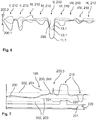
- Figure 6 shows the course of the sensor signals 11.1, 12.1, 13.1 and the specific directions of deviation 200.1, 200.2.
- the sensor signals 11.1, 12.1, 13.1 each run differently in relation to different positions I to IX on the operating body 2.
- Positions I to IX on the control body 2 are in Figure 5 shown, preferably wherein the sensor elements 11, 12, 13 are arranged at the positions IV to VI or at the position V behind the operating body 2. Pressing the respective positions I to IX on the operating body 2 leads to different deformations of the operating body 2, which are mapped by the specific deviation directions 200.1, 200.2 of the sensor signals 11.1, 12.1, 13.1.
- the in Figure 6 The course shown is to be understood only schematically and may differ for positions I to IX.
- an actuation force F generates different signal amplitudes 210 of the sensor signals 11.1, 12.1, 13.1 of the three sensor elements 11, 12, 13 on one of the positions I to IX on the operating body 2.
- the directions of deviation 200.1, 200.2 relate refers to a reference 200, from which the signal amplitudes 210 proceed.
- an actuation force at position I of the operating body 2 leads to a compressive stress state or a negative deformation in the area of the first and second sensor elements 11, 12 and thus to a negative direction of deviation 200.1 of the sensor signals 11.1, 12.1, but at the same time to a tensile stress state in the area of the third sensor element 13 and thus to a positive deformation, which in turn leads to a specific deviation direction 200.2 in the positive direction.
- a specific image of the sensor signals 11.1, 12.1, 13.1 can be present for each of the positions I to IX and thus the deformation can be localized and the actuation can be recognized as a function of the localization.
- the detection 106 of the actuation of the sensor device 10 is provided for the case that the actuation force F is localized at the central position V, ie in the center of the sensor device 10. This can be recognized, for example, from the fact that all specific deviation directions 200.1 are negative.
- the sensor signals 11.1, 12.1, 13.1 are generated 101, 102, 103 in particular for each of the sensor elements 11, 12, 13 separately and / or simultaneously.
- the sensor signals 11.1, 12.1, 13.1 can preferably be processed measurement signals, wherein in particular a mean value can be formed in each case in order to generate the sensor signals 11.1, 12.1, 13.1.
- Figure 7 also shows, by way of example, using a single sensor signal 11.1, how this can be advantageously interpreted in order to avoid false triggering.
- removal 104 of undesired signal interference 200.3 is provided.
- the control unit 20 can have a filter module 22 for removing 104 undesired signal interference 200.3.
- an adaptation 105 of the reference 200 to the deformation state of the operating body 2, in particular by a compensation module 23 of the control unit 20, is provided while the sensor signal 11.1 is being generated.
- a reference limit value 201 is specified, from which the adaptation 105 of the reference 200 is interrupted, so that the signal amplitude 210 of the sensor signal 11.1 is detected based on the reference limit value 201 in order to detect the deformation.
- the reference limit value 201 can be an absolute value or a time-dependent parameter.
- a deactivation parameter 203 and a triggering parameter 202 are also specified, in particular by a memory module 25 of the control unit 20, and are also carried along when the reference 200 is adjusted 105. This results in a recalibration during operation of the sensor device 10, in which the criteria for the actuation or non-actuation of the sensor device 10 are shifted and adapted to the current state of deformation of the operating body 2.
- the triggering parameter 202 is provided so that an output 107 of an actuation signal 220 is started by an output module 24 of the control unit 20.
- the trigger parameter 202 and the deactivation parameter 203 can be identical.
- the actuation signal 220 can be used to control the electrical function of the functional unit 3 of the motor vehicle 1, the actuation signal 220 having an actuation amplitude 221, the direction of which is independent of the reference 200.
- an unambiguous actuation signal 220 can be output which can accordingly be interpreted in a simple manner by the functional unit 3 and / or a subsequent control unit. If the deactivation parameter 203 is reached by the respective signal amplitude 210 after the triggering, the output 107 of the actuation signal 220 is stopped.
- the actuation signal 220 can be completely suspended or signal non-actuation.
Landscapes
- Force Measurement Appropriate To Specific Purposes (AREA)
Abstract
Die Erfindung betrifft ein Verfahren (100) zum Betreiben einer Sensorvorrichtung (10) für eine Betätigung durch eine Deformation eines Bedienkörpers (2) umfassend die folgenden Schritte:- Erzeugen (101) eines ersten Sensorsignals (11.1) infolge einer Deformation des Bedienkörpers (2),- Erzeugen (102) eines zweiten Sensorsignals (12.1) infolge der Deformation des Bedienkörpers (2),- Erkennen (106) der Betätigung in Abhängigkeit von jeweils zumindest einer spezifischen Abweichungsrichtung (200.1, 200.2) des ersten und zweiten Sensorsignals (11.1, 12.1) von einer Referenz (200).Ferner betrifft die Erfindung ein Computerprogrammprodukt (300), eine Sensorvorrichtung (10) für eine Betätigung durch eine Deformation eines Bedienkörpers (2) sowie ein Fahrzeug (1).The invention relates to a method (100) for operating a sensor device (10) for actuation by deformation of an operating body (2), comprising the following steps: generating (101) a first sensor signal (11.1) as a result of a deformation of the operating body (2) - generating (102) a second sensor signal (12.1) as a result of the deformation of the operating body (2), - detecting (106) the actuation as a function of at least one specific direction of deviation (200.1, 200.2) of the first and second sensor signals (11.1, 12.1) The invention also relates to a computer program product (300), a sensor device (10) for actuation by deformation of an operating body (2), and a vehicle (1).
Description
Die Erfindung betrifft ein Verfahren zum Betreiben einer Sensorvorrichtung für eine Betätigung durch eine Deformation eines Bedienkörpers, ein Computerprogrammprodukt, eine Sensorvorrichtung für eine Betätigung durch eine Deformation eines Bedienkörpers sowie ein Fahrzeug.The invention relates to a method for operating a sensor device for actuation by deformation of an operating body, a computer program product, a sensor device for actuation by deformation of an operating body and a vehicle.
Aus dem Stand der Technik sind tast- und/oder druckempfindliche Sensoren sowie Näherungssensoren bei Fahrzeugen bekannt. Die druckempfindlichen Sensoren sind dabei meist von außen zugänglich oder mit einem Betätigungselement verbunden, welches bewegbar ist, um den Drucksensor auszulösen. Als Reaktion auf eine Auslösung des Sensors werden dabei häufig Fahrzeugfunktionen aktiviert. Z. B. kann ein elektronisches Schloss aktiviert werden.Touch and / or pressure-sensitive sensors and proximity sensors in vehicles are known from the prior art. The pressure-sensitive sensors are mostly accessible from the outside or are connected to an actuating element which can be moved in order to trigger the pressure sensor. In response to the sensor being triggered, vehicle functions are often activated. For example, an electronic lock can be activated.
Dabei ist jedoch von Nachteil, dass die tast- und/oder druckempfindlichen Sensoren im Normalfall einen Durchbruch einer Außenfläche erfordern, was konstruktive Einschränkungen sowie gestalterische Nachteile mit sich bringen kann. Daher ist es bspw. aus der
Es ist somit eine Aufgabe der vorliegenden Erfindung voranstehende aus dem Stand der Technik bekannte Nachteile zumindest teilweise zu beheben. Insbesondere ist eine Aufgabe der vorliegenden Erfindung, ein Verarbeiten einer Deformation und/oder ein Erkennen einer Betätigung einer Sensorvorrichtung zu verbessern, vorzugsweise durch eine verbesserte Genauigkeit bei einer Deformationserkennung, insbesondere um Fehlauslösungen zu reduzieren oder zu vermeiden.It is therefore an object of the present invention to at least partially remedy the above disadvantages known from the prior art. In particular, it is an object of the present invention to improve the processing of a deformation and / or the detection of an actuation of a sensor device, preferably by means of improved accuracy in a deformation detection, in particular in order to reduce or avoid false triggering.
Die voranstehende Aufgabe wird gelöst durch ein Verfahren mit den Merkmalen des unabhängigen Verfahrensanspruch, ein Computerprogrammprodukt mit den Merkmalen unabhängigen Computerprogrammprodukt-Anspruchs, eine Sensorvorrichtung mit den Merkmalen des unabhängigen Vorrichtungsanspruchs sowie ein Kraftfahrzeug mit den Merkmalen des unabhängigen Fahrzeuganspruchs. Weitere Merkmale und Details der Erfindung ergeben sich aus den Unteransprüchen, der Beschreibung und den Zeichnungen. Dabei gelten Merkmale und Details, die im Zusammenhang mit dem erfindungsgemäßen Verfahren beschrieben worden sind, selbstverständlich auch im Zusammenhang mit dem erfindungsgemäßen Computerprogrammprodukt, der erfindungsgemäßen Sensorvorrichtung und/oder dem erfindungsgemäßen Fahrzeug und jeweils umgekehrt, sodass bzgl. der Offenbarung zu den einzelnen Erfindungsaspekten stets wechselseitig Bezug genommen wird bzw. werden kann.The above object is achieved by a method with the features of the independent method claim, a computer program product with the features of the independent computer program product claim, a sensor device with the features of the independent device claim and a motor vehicle with the features of the independent vehicle claim. Further features and details of the invention emerge from the subclaims, the description and the drawings. Features and details that have been described in connection with the method according to the invention naturally also apply in connection with the computer program product according to the invention, the sensor device according to the invention and / or the vehicle according to the invention and in each case vice versa, so that the disclosure of the individual aspects of the invention is always reciprocal Is or can be referred to.
Erfindungsgemäß umfasst ein Verfahren zum Betreiben einer Sensorvorrichtung für eine Betätigung, insbesondere durch einen Benutzer zum Auslösen einer elektrischen Funktion, durch eine Deformation eines Bedienkörpers, insbesondere eines Fahrzeuges, die folgenden Schritte:
- Erzeugen eines ersten Sensorsignals, insbesondere durch ein erstes Sensorelement, infolge der Deformation des Bedienkörpers,
- Erzeugen eines zweiten Sensorsignals, insbesondere durch ein zweites Sensorelement, infolge der Deformation des Bedienkörpers,
- Erkennen der Betätigung in Abhängigkeit von jeweils zumindest einer spezifischen Abweichungsrichtung des ersten und zweiten Sensorsignals von einer Referenz.
- Generating a first sensor signal, in particular by a first sensor element, as a result of the deformation of the operating body,
- Generation of a second sensor signal, in particular by a second sensor element, as a result of the deformation of the operating body,
- Detecting the actuation as a function of at least one specific direction of deviation of the first and second sensor signals from a reference.
Das erste und zweite Sensorsignal können Messsignale von (einem ersten und zweiten) Sensorelementen einer Sensorvorrichtung sein. Idealerweise weist jedes Sensorelement ein eigenes Sensorsignal auf. Auch können mehr als zwei Sensorelemente bei der Sensorvorrichtung vorgesehen sein. Ferner ist es denkbar, dass die Messsignale der Sensorelemente beim Erzeugen der Sensorsignale zumindest teilweise ausgewertet werden. Der Bedienkörper kann z.B. ein bewegliches Teil eines Fahrzeugs umfassen. Vorzugsweise kann es sich bei dem Bedienkörper um ein Fahrzeugblech handeln. Das erste und zweite Sensorsignal können induktiv erzeugt werden, indem z.B. den Sensorsignalen zugeordnete Sensorelemente eine Spule aufweisen, um die induktive Messung zu ermöglichen, wenn sich ein magnetisierbarer und/oder elektrisch leitfähiger Körper den Sensorelementen durch die Deformation nähert. Es ist jedoch ebenso denkbar, dass bspw. eine Metallplatte oder eine metallische Beschichtung auf den Bedienkörper im Bereich der Sensorelemente aufgebracht, insbesondere aufgeklebt, ist, um in Folge einer Deformation des Bedienkörpers eine Auslenkung des Metallkörpers (auch in Form einer metallische Beschichtung) zu bewirken, welche durch die Sensorelemente detektierbar ist.The first and second sensor signals can be measurement signals from (a first and second) sensor elements of a sensor device. Ideally, each sensor element has its own sensor signal. More than two sensor elements can also be provided in the sensor device. It is also conceivable that the measurement signals of the sensor elements are at least partially evaluated when generating the sensor signals. The operating body can e.g. comprise a moving part of a vehicle. The operating body can preferably be a vehicle panel. The first and second sensor signals can be generated inductively, e.g. Sensor elements assigned to the sensor signals have a coil in order to enable the inductive measurement when a magnetizable and / or electrically conductive body approaches the sensor elements due to the deformation. However, it is also conceivable that, for example, a metal plate or a metallic coating is applied, in particular glued, to the operating body in the area of the sensor elements in order to cause a deflection of the metal body (also in the form of a metallic coating) as a result of a deformation of the operating body which can be detected by the sensor elements.
Unter der Referenz kann vorzugsweise ein Referenzsignal oder ein Referenzwert verstanden werden. Die spezifische Abweichungsrichtung des jeweiligen Sensorsignals kann eine Richtung einer Signalamplitude des jeweiligen Sensorsignals umfassen. Ferner kann die Abweichungsrichtung einen vollständig abweichenden Verlauf des ersten und/oder zweiten Sensorsignals umfassen, wenn z.B. aufgrund der Deformation das erste und/oder zweite Sensorsignal sich von der Referenz entfernt. Unter spezifisch kann insbesondere verstanden werden, dass die Abweichungsrichtung vorgegeben oder anlernbar ist, um die Deformation und/oder Betätigung zu erkennen. So kann z.B. ein Abbild der spezifischen Abweichungsrichtung vorgegeben sein, welches einen typischen Deformationszustand wiederspiegelt. Das Erkennen der Betätigung in Abhängigkeit der Abweichungsrichtungen kann somit ein Bewerten der Abweichungsrichtungen und/oder den Sensorsignale umfassen.The reference can preferably be understood as a reference signal or a reference value. The specific direction of deviation of the respective sensor signal can include a direction of a signal amplitude of the respective sensor signal. Furthermore, the direction of deviation can include a completely different course of the first and / or second sensor signal if, for example, due to the deformation, the first and / or second sensor signal moves away from the reference. Specific can in particular be understood to mean that the direction of deviation is predetermined or can be learned in order to recognize the deformation and / or actuation. For example, an image of the specific direction of deviation can be specified, which reflects a typical deformation state. The detection of the actuation as a function of the directions of deviation can thus include an evaluation of the directions of deviation and / or the sensor signals.
Dadurch dass zum Erkennen der Betätigung anhand der Deformation zumindest zwei Sensorsignale herangezogen werden, können Messfehler der einzelnen Signale ausgeglichen werden. Darüber hinaus ist über die Abweichungsrichtung unterscheidbar, ob es sich bei der Deformation um eine positive oder eine negative Auslenkung des Bedienkörpers handelt. Somit kann bspw. vorbestimmt sein, dass eine Auslösung einer Betätigungsfunktion dann durchgeführt wird, wenn zum einen eine Deformation festgestellt wird und diese zum anderen als Druck auf den Bedienkörper erkannt wird. Darüber hinaus kann über die spezifische Abweichungsrichtung des ersten und zweiten Sensorsignals ein Signalbild vorgegeben sein, welches ein Charakteristikum für eine bewusste (gewollte) Deformation des Bedienkörpers zum Auslösen einer Betätigung darstellt. So ist es bspw. denkbar, dass die Abweichungsrichtungen des ersten und zweiten Sensorsignals einen Druckzustand des Bedienkörpers aufzeigen, und deren jeweilige Signalamplitude den gleichen Ausschlag aufweist. Dadurch kann mit einer hohen Genauigkeit festgestellt werden, dass die Deformation zwischen den Sensorelementen stattgefunden hat oder stattfindet und somit z.B. zur Betätigung erkannt wird.Because at least two sensor signals are used to detect the actuation based on the deformation, measurement errors of the individual signals can be compensated for. In addition, the direction of deviation can be used to distinguish whether the deformation is a positive or a negative deflection of the operating body. It can thus be predetermined, for example, that an actuation function is triggered when, on the one hand, a deformation is detected and, on the other hand, this is recognized as pressure on the operating body. In addition, a signal image can be specified via the specific direction of deviation of the first and second sensor signals, which represents a characteristic for a conscious (intentional) deformation of the operating body for triggering an actuation. For example, it is conceivable that the directions of deviation of the first and second sensor signals indicate a pressure state of the operating body, and their respective signal amplitudes have the same deflection. This makes it possible to determine with a high degree of accuracy that the deformation has taken place or is taking place between the sensor elements and thus e.g. is recognized for actuation.
Vorzugsweise kann die Deformation beim Erkennen der Betätigung in Abhängigkeit der spezifischen Abweichungsrichtungen des ersten und zweiten Sensorsignals lokalisiert werden. Insbesondere kann anhand der spezifischen Abweichungsrichtungen des ersten und zweiten Sensorsignals ausgehend von der Referenz eine Position der Deformation erkannt werden. Weist z.B. das erste Sensorsignal eine negative Abweichungsrichtung auf und das zweite Sensorsignal eine positive Abweichungsrichtung, so kann davon ausgegangen werden, dass sich der Bedienkörper im Bereich des ersten Sensorelementes in einem Druckspannungszustand befindet und im Bereich des zweiten Sensorelementes in einem Zugspannungszustand, wobei der Druckspannungszustand zu einer Auslenkung des Bedienkörpers in Richtung der Sensorelemente führt und der Zugspannungszustand zu einer Auslenkung des Bedienkörpers entgegen der Richtung der Sensorelemente. Insbesondere in Abhängigkeit von einer Befestigung der Sensorelemente am Bedienkörper, können bspw. unterschiedliche Betätigungswünsche je nach Druckposition durch das erste und zweite Sensorsignal detektiert werden und/oder von Fehlbetätigungen unterschieden werden.When the actuation is recognized, the deformation can preferably be localized as a function of the specific directions of deviation of the first and second sensor signals. In particular, based on the reference, a position of the deformation can be recognized on the basis of the specific deviation directions of the first and second sensor signals. For example, if the first sensor signal has a negative direction of deviation and the second sensor signal has a positive direction of deviation, it can be assumed that the operating body is in a compressive stress state in the area of the first sensor element and in a tensile stress state in the area of the second sensor element, the compressive stress state being assigned a deflection of the Operating body leads in the direction of the sensor elements and the tensile stress state leads to a deflection of the operating body counter to the direction of the sensor elements. In particular, depending on the attachment of the sensor elements to the operating body, for example different actuation requests can be detected by the first and second sensor signals depending on the printing position and / or can be distinguished from incorrect actuations.
Vorzugsweise kann bei einem erfindungsgemäßen Verfahren vorgesehen sein, dass zusätzlich zu den Abweichungsrichtungen jeweils zumindest eine Signalamplitude des ersten und zweiten Sensorsignals beim Erkennen der Betätigung berücksichtigt wird. Somit kann nicht nur die Richtung zum Lokalisieren der Deformation herangezogen werden, sondern zusätzlich die jeweilige Signalamplitude selbst. Bei der Signalamplitude kann es sich insbesondere um eine Abweichungsgröße von der Referenz handeln. Durch die Berücksichtigung der Signalamplitude kann somit auch eine Stärke der Auslenkung identifiziert werden und somit einer beabsichtigten oder unbeabsichtigten Betätigungshandlung zugeordnet werden. Dadurch, dass dies für das erste und zweite Sensorsignal berücksichtigt wird, kann ferner die Genauigkeit der Lokalisation der Deformation verbessert sein. Insbesondere kann ein vollständiges Signalbild der Sensorsignale vorgegeben sein, das ein Charakteristikum einer beabsichtigten Betätigungshandlung darstellt. Es kann vorgesehen sein, dass die Deformation erst als beabsichtigte Betätigungshandlung erkannt wird, wenn die Sensorsignale das vorgegebene Signalbild wiederspiegeln.In a method according to the invention, it can preferably be provided that, in addition to the directions of deviation, at least one signal amplitude of the first and second sensor signals is taken into account when the actuation is recognized. Thus, not only the direction can be used to localize the deformation, but also the respective signal amplitude itself. The signal amplitude can in particular be a deviation from the reference. By taking the signal amplitude into account, a strength of the deflection can thus also be identified and thus assigned to an intended or unintentional actuation. Because this is taken into account for the first and second sensor signals, the accuracy of the localization of the deformation can also be improved. In particular, a complete signal image of the sensor signals can be specified, which represents a characteristic of an intended actuation action. It can be provided that the deformation is only recognized as an intended actuation action when the sensor signals reflect the specified signal image.
Ferner kann bei einem erfindungsgemäßen Verfahren vorgesehen sein, dass das Verfahren folgenden Schritt umfasst:
- Erzeugen eines dritten Sensorsignals, insbesondere durch ein drittes Sensorelement, infolge der Deformation des Bedienkörpers,
- Generation of a third sensor signal, in particular by a third sensor element, as a result of the deformation of the operating body,
Im Rahmen der Erfindung ist es ferner denkbar, dass das Verfahren folgenden Schritt umfasst:
- Entfernen unerwünschter Signalstörungen, insbesondere in Form von Signalspitzen des ersten und/oder zweiten Sensorsignals.
- Removal of unwanted signal interference, in particular in the form of signal peaks of the first and / or second sensor signal.
Vorzugsweise wird bei einem erfindungsgemäßen Verfahren beim Erzeugen des ersten und/oder zweiten Sensorsignals jeweils ein Mittelwert eines Messsignals gebildet. Die Sensorsignale können somit aufbereitete Messignale umfassen. Durch die Mittelwertbildung können weitere Störgrößen in den Sensorsignalen reduziert werden und damit die Erkennung der Deformation verbessert sein. Der Mittelwert kann ein Arithmetisches Mittel und/oder einen Median umfassen. Zur Bildung des Mittelwertes können eine Signalstärke, eine Signalfrequenz und/oder dergleichen herangezogen werden. Insbesondere können somit weitere Signalschwankungen eines Messsignals ausgeglichen werden und zu einem Sensorsignal verarbeitet werden, welches in Bezug auf die Deformation einfacher auszuwerten ist.In a method according to the invention, when generating the first and / or second sensor signal, a mean value of a measurement signal is preferably formed. The sensor signals can thus include processed measurement signals. The averaging can reduce further disturbance variables in the sensor signals and thus improve the detection of the deformation. The mean value can comprise an arithmetic mean and / or a median. A signal strength, a signal frequency and / or the like can be used to form the mean value. In particular, further signal fluctuations of a measurement signal can thus be compensated for and processed into a sensor signal which is easier to evaluate with regard to the deformation.
Ferner kann ein erfindungsgemäßes Verfahren folgenden Schritt umfassen:
- Anpassen der Referenz an einen (ungewollten oder gewollten) Deformationszustand des Bedienkörpers, insbesondere während des Erzeugens des ersten und/oder zweiten Sensorsignals.
- Adaptation of the reference to an (unwanted or wanted) deformation state of the operating body, in particular during the generation of the first and / or second sensor signal.
Weiterhin kann bei einem erfindungsgemäßen Verfahren vorgesehen sein, dass zumindest ein Referenzgrenzwert vorgegeben wird, ab welchem das Anpassen der Referenz unterbrochen wird, insbesondere sodass eine Signalamplitude ausgehend vom Referenzgrenzwert erfasst wird. So kann vorgesehen sein, dass das Anpassen der Referenz bis zu einem vorbestimmten Wert, d.h. dem Referenzgrenzwert, durchgeführt wird. Der Referenzgrenzwert kann z.B. anhand von üblichen Temperaturschwankungen und der daraus folgenden Deformation des Bedienkörpers vorbestimmt sein. Durch den Referenzgrenzwert kann eine einfache Möglichkeit geschaffen sein eine Referenzwertnachführung zu realisieren und eine Betätigung erkennen zu können. Weiterhin kann vorgesehen sein, dass der Referenzgrenzwert zeitabhängig ist. Dadurch können z.B. sich langsam verändernde Deformationen von schnellen Deformationen unterschieden werden.Furthermore, it can be provided in a method according to the invention that at least one reference limit value is specified from which the adaptation of the reference is interrupted, in particular so that a signal amplitude is detected based on the reference limit value. It can thus be provided that the adjustment of the reference up to a predetermined value, i. the reference limit value. The reference limit value can e.g. be predetermined on the basis of usual temperature fluctuations and the resulting deformation of the operating body. The reference limit value can create a simple possibility of realizing a reference value tracking and being able to recognize an actuation. It can also be provided that the reference limit value is time-dependent. As a result, e.g. Slowly changing deformations can be distinguished from fast deformations.
Grundsätzlich kann bei der Anpassen der Referenz an den (ungewollten / gewollten) Deformationszustand (im Rahmen der Erfindung) zwischen der
- a) ungewollten Änderung des Deformationszustandes des Bedienkörpers (ungewollte Deformation) durch äußere unvermeidbare Einflüsse, wie z.B. Umwelteinflüsse (Temperatur-, Druck-, Schallveränderungen) etc., und
- b) der gewollten Änderung des Deformationszustandes des Bedienkörpers (gewollte Deformation) durch gewollte Einflüsse durch einen Bediener bei einer Betätigung des Bedienkörpers
In den beiden Fällen a) und b) kann ein Anpassen der Referenz an einen Deformationszustand des Bedienkörpers in Abhängigkeit von der Abweichung des Sensorsignals (wie zuvor im Text aufgeführt) erfolgen. Auch ist es denkbar, dass nur bei der ungewollten Änderung des Deformationszustandes des Bedienkörpers (Fall a)) die Anpassen der Referenz an einen Deformationszustand des Bedienkörpers in Abhängigkeit von der Abweichung des Sensorsignals erfolgt. Die ungewollte Änderung des Deformationszustandes ist messtechnisch bspw. durch die Geschwindigkeit der Änderung des Deformationszustandes und/oder durch die maximale Änderung des Deformationszustandes innerhalb einer Zeitspanne ΔT von der gewollten Änderung des Deformationszustandes deutlich zu unterscheiden.Basically, when adapting the reference to the (unwanted / wanted) deformation state (within the scope of the invention) between the
- a) unwanted change in the deformation state of the control body (unwanted deformation) due to external unavoidable influences, such as environmental influences (temperature, pressure, sound changes) etc., and
- b) the desired change in the deformation state of the control element (desired deformation) due to deliberate influences by an operator when the control element is actuated
In both cases a) and b), the reference can be adapted to a state of deformation of the operating body as a function of the deviation of the sensor signal (as stated previously in the text). It is also conceivable that the adaptation of the reference to a deformation state of the operating body takes place as a function of the deviation of the sensor signal only in the event of an undesired change in the deformation state of the operating body (case a)). The unwanted change in the deformation state is metrologically, for example, due to the speed of the change of the state of deformation and / or by the maximum change in the state of deformation within a period of time .DELTA.T to be clearly differentiated from the desired change in the state of deformation.
Weiterhin kann bei einem erfindungsgemäßen Verfahren vorgesehen sein, dass das Verfahren folgenden Schritt umfasst:
- Ausgeben eines Betätigungssignals zum Ansteuern einer elektrischen Funktion, insbesondere wobei das Betätigungssignal eine Betätigungsamplitude aufweist, deren Richtung unabhängig von der Referenz ist.
- Outputting an actuation signal for controlling an electrical function, in particular wherein the actuation signal has an actuation amplitude, the direction of which is independent of the reference.
Vorzugsweise kann einem erfindungsgemäßen Verfahren ein Auslöseparameter vorgegeben werden und das Ausgeben des Betätigungssignals erfolgen, wenn der Auslöseparameter durch zumindest eines der Sensorsignale oder alle Sensorsignale, insbesondere zumindest eine der Signalamplituden der Sensorsignale, erreicht wird. Durch den Auslöseparameter kann ein Auslösekriterium gegeben sein, welches sich auf die Signalamplitude des ersten und/oder zweiten Sensorsignals bezieht. Somit kann bis zum Ausgeben des Betätigungssignals nicht nur gefordert sein, dass die Deformation eine spezifische Abweichungsrichtung aufweist, d.h. insbesondere an einer bestimmten Position erfolgt, sondern ferner auch über eine bestimmte Zeit aufrecht erhalten wird. Ferner kann der Deformationszustand eine bestimmte Deformationsstärke aufweisen, die sich in der Signalamplitude wiederspiegeln kann.A trigger parameter can preferably be specified for a method according to the invention and the actuation signal can be output if the trigger parameter is achieved by at least one of the sensor signals or all sensor signals, in particular at least one of the signal amplitudes of the sensor signals. The triggering parameter can provide a triggering criterion that relates to the signal amplitude of the first and / or second sensor signal. Thus, until the actuation signal is output, it may not only be required that the deformation has a specific direction of deviation, ie in particular takes place at a specific position, but also is maintained over a specific time. Furthermore, the Deformation state have a certain degree of deformation, which can be reflected in the signal amplitude.
Ferner kann bei einem erfindungsgemäßen Verfahren ein Deaktivierungsparameter vorgegeben werden und das Ausgeben des Betätigungssignals angehalten werden, wenn der Deaktivierungsparameter während des Ausgebens des Betätigungssignals durch zumindest eines der Sensorsignale, insbesondere zumindest eine der Signalamplituden der Sensorsignale, erreicht wird. Unter dem Anhalten des Betätigungssignals kann verstanden werden, dass das Betätigungssignal vollständig ausgesetzt wird oder einen Signalverlauf aufweist, welcher eine Nichtbetätigung signalisiert. Der Deaktivierungsparameter kann vorzugsweise mit der Referenz angepasst werden. Insbesondere kann der Deaktivierungsparameter einen Schwellwert entgegengesetzt zur Abweichungsrichtung der Sensorsignale bilden, ab welchem ein Stopp der Betätigungshandlung erkannt wird. Somit kann z.B. durch den Auslöseparameter ein oberer Schwellwert gegeben sein, ab welchen die Betätigungshandlung ausgelöst wird und wenn das Sensorsignal unter den Deaktivierungsparameter fällt kann ein Stopp der Betätigung erkannt werden.Furthermore, in a method according to the invention, a deactivation parameter can be specified and the outputting of the actuation signal can be stopped if the deactivation parameter is reached by at least one of the sensor signals, in particular at least one of the signal amplitudes of the sensor signals, while the actuation signal is being output. Stopping the actuation signal can be understood to mean that the actuation signal is completely suspended or has a signal profile which signals non-actuation. The deactivation parameter can preferably be adapted with the reference. In particular, the deactivation parameter can form a threshold value opposite to the direction of deviation of the sensor signals, from which a stop of the actuation action is recognized. Thus e.g. an upper threshold value from which the actuation action is triggered and if the sensor signal falls below the deactivation parameter can be recognized as a stop of the actuation can be given by the trigger parameter.
Vorzugsweise kann bei einem erfindungsgemäßen Verfahren vorgesehen sein, dass der Auslöseparameter und/oder der Deaktivierungsparameter in Abhängigkeit von der Referenz angepasst werden. Somit kann eine Referenzwertnachführung auch auf den Auslöseparameter und/oder Deaktivierungsparameter übertragen werden, sodass in Abhängigkeit von der Referenzwertnachführung auf einfache Art und Weise die Betätigung erkannt werden kann. Dadurch können äußere Einflüsse auf den Deformationszustand des Bedienkörpers berücksichtigt werden und zu einer verbesserten Genauigkeit bzw. einer Reduktion von Fehlbetätigungen führen. Vorzugsweise kann für jede der Abweichungsrichtungen ein Auslöseparameter und/oder ein Deaktivierungsparameter vorgegeben und/oder angepasst werden.In a method according to the invention, provision can preferably be made for the triggering parameter and / or the deactivation parameter to be adapted as a function of the reference. A reference value tracking can thus also be transferred to the triggering parameter and / or deactivation parameter, so that the actuation can be recognized in a simple manner as a function of the reference value tracking. As a result, external influences on the deformation state of the operating body can be taken into account and lead to improved accuracy or a reduction in incorrect actuations. A trigger parameter and / or a deactivation parameter can preferably be specified and / or adapted for each of the deviation directions.
Gemäß einem weiteren Aspekt der Erfindung ist ein Computerprogrammprodukt beansprucht. Das Computerprogrammprodukt umfasst Befehle, die bei einer Ausführung, insbesondere der Befehle und/oder des Programms, durch eine Kontrolleinheit die Kontrolleinheit veranlassen ein erfindungsgemäßes Verfahren auszuführen.According to a further aspect of the invention, a computer program product is claimed. The computer program product comprises commands which, when the commands and / or the program are executed by a control unit, cause the control unit to carry out a method according to the invention.
Somit kann das Verfahren insbesondere durch Ausführung der Befehle bzw. des Programms durch die Kontrolleinheit durchgeführt werden. Das Computerprogrammprodukt kann als Anweisungscode in einer Programmiersprache, wie z.B. Java, C++ oder dergleichen implementiert sein. Bei der Kontrolleinheit kann es sich um eine Rechnereinheit, einen Mikroprozessor und/oder dergleichen handeln. Insbesondere kann der Anweisungscode die Kontrolleinheit derart programmieren, dass die gewünschten Funktionen ausgeführt werden. Das Computerprogrammprodukt kann in einem Netzwerk, z.B. dem Internet oder einem lokalen Netzwerk, bereitgestellt werden und/oder herunterladbar sein. Ferner ist es denkbar, dass das Computerprogrammprodukt durch eine oder mehrere elektronische Schaltungen in Hardware oder in beliebig hybrider Form, d.h. mittels Softwarekomponenten und Hardwarekomponenten realisiert werden bzw. sein kann.The method can thus be carried out in particular by executing the commands or the program by the control unit. The computer program product can be written as instruction code in a programming language, e.g. Java, C ++ or the like can be implemented. The control unit can be a computer unit, a microprocessor and / or the like. In particular, the instruction code can program the control unit in such a way that the desired functions are carried out. The computer program product can be in a network, e.g. the Internet or a local area network, provided and / or downloadable. Furthermore, it is conceivable that the computer program product can be implemented by one or more electronic circuits in hardware or in any hybrid form, i.e. can be or can be implemented by means of software components and hardware components.
Gemäß einem weiteren Aspekt der Erfindung ist eine Sensorvorrichtung für eine Betätigung durch eine Deformation eines Bedienkörpers beansprucht. Die Sensorvorrichtung weist zumindest ein erstes und ein zweites Sensorelement auf, die zum Erfassen einer Deformation des Bedienkörpers jeweils in einem Abstand zum Bedienkörper anordbar sind. Ferner weist die Sensorvorrichtung eine Kontrolleinheit zum Auswerten eines ersten Sensorsignals des ersten Sensorelementes infolge der Deformation und eines zweiten Sensorsignals des zweiten Sensorelementes infolge der Deformation auf. Weiterhin weist die Kontrolleinheit ein Erkennungsmodul zum Erkennen der Betätigung in Abhängigkeit von jeweils zumindest einer spezifischen Abweichungsrichtung des ersten und zweiten Sensorsignals von einer Referenz auf.According to a further aspect of the invention, a sensor device is claimed for actuation by deformation of an operating body. The sensor device has at least a first and a second sensor element, which can each be arranged at a distance from the operating body in order to detect a deformation of the operating body. The sensor device also has a control unit for evaluating a first sensor signal from the first sensor element as a result of the deformation and a second sensor signal from the second sensor element as a result of the deformation. Furthermore, the control unit has a recognition module for recognizing the actuation as a function of at least one specific direction of deviation of the first and second sensor signals from a reference.
Die Sensorsignale können sich auf einen Mittelwert insbesondere von Signalamplituden, des ersten und/oder zweiten Sensorelementes beziehen. Insbesondere kann ferner die Referenz auf einen Mittelwert bezogen sein. Weiterhin kann das Erkennungsmodul zum Lokalisieren der Deformation in Bezug auf das erste und zweite Sensorelement ausgebildet sein. Die spezifische Abweichungsrichtung kann eine positive und/oder negative Richtung des Sensorsignals, insbesondere einer Signalamplitude des Sensorsignals, umfassen. Vorzugsweise können das erste und zweite Sensorelement den gleichen Abstand zum Bedienkörper aufweisen und/oder gemeinsam am Bedienkörper als Baueinheit anordbar sein. Somit bringt eine erfindungsgemäße Sensorvorrichtung die gleichen Vorteile mit sich, wie sie bereits ausführlich mit Bezug auf ein erfindungsgemäßes Verfahren beschrieben worden sind. Vorzugsweise kann bei einer erfindungsgemäßen Sensorvorrichtung vorgesehen sein, dass die Kontrolleinheit, insbesondere das Erkennungsmodul, zum Ausführen eines erfindungsgemäßen Verfahrens ausgebildet ist.The sensor signals can relate to a mean value, in particular of signal amplitudes, of the first and / or second sensor element. In particular, the reference can also be related to a mean value. Furthermore, the detection module can be designed to localize the deformation in relation to the first and second sensor elements. The specific direction of deviation can include a positive and / or negative direction of the sensor signal, in particular a signal amplitude of the sensor signal. The first and second sensor elements can preferably have the same distance from the operating body and / or can be arranged together on the operating body as a structural unit. A sensor device according to the invention thus brings the same advantages as have already been described in detail with reference to a method according to the invention have been. In a sensor device according to the invention, it can preferably be provided that the control unit, in particular the detection module, is designed to carry out a method according to the invention.
Vorzugsweise kann bei einer erfindungsgemäßen Sensorvorrichtung das erste und zweite Sensorelement mit einem Befestigungselement verbunden sein, durch welches das erste und zweite Sensorelement am Bedienkörper befestigbar sind. Zusätzlich oder alternativ kann die Sensorvorrichtung zumindest eine Anschlussleitung zum Anschluss des ersten oder zweiten Sensorelementes an eine Elektronik aufweisen. Die Anschlussleitung kann separat zum Befestigungselement am Bedienkörper oder einem weiteren Bauteil befestigbar sein. Durch das Befestigungselement, welches das erste und zweite Sensorelement verbindet, kann somit eine Baueinheit geschaffen sein, durch welche das erste und zweite Sensorelement in einfacher Art und Weise in einem definierten Abstand zueinander und/oder zum Bedienkörper am Bedienkörper anordbar sind. Darüber hinaus kann durch das Befestigungselement sichergestellt sein, dass die Sensorelemente auch im Betrieb aneinandergekoppelt sind, d.h. z.B. bei einer Bewegung des Bedienkörpers dieser Bewegung gleichzeitig folgen können.In a sensor device according to the invention, the first and second sensor elements can preferably be connected to a fastening element by means of which the first and second sensor element can be fastened to the operating body. Additionally or alternatively, the sensor device can have at least one connection line for connecting the first or second sensor element to electronics. The connection line can be fastened separately to the fastening element on the operating body or a further component. The fastening element which connects the first and second sensor elements can thus create a structural unit by means of which the first and second sensor elements can be arranged in a simple manner at a defined distance from one another and / or from the operating body on the operating body. In addition, the fastening element can ensure that the sensor elements are also coupled to one another during operation, i.e. e.g. can follow this movement at the same time when the operating body moves.
Vorzugsweise kann bei einer erfindungsgemäßen Sensorvorrichtung vorgesehen sein, dass das Befestigungselement zumindest zwei Befestigungsabschnitte aufweist, zwischen denen das erste und zweite Sensorelement angeordnet sind. Die Befestigungsabschnitte können insbesondere miteinander verbunden sein. Vorzugsweise können die Befestigungsabschnitte einen ringförmigen Befestigungsbereich bilden. Das erste und zweite Sensorelement können innerhalb des ringförmigen Befestigungsbereiches angeordnet sein. Durch die zumindest zwei Befestigungsabschnitte zwischen denen das erste und zweite Sensorelement angeordnet sind, kann z.B. eine symmetrische Kraft außerhalb der Sensorelemente und insbesondere außerhalb der Befestigungsabschnitte von einer zentralen Betätigungskraft unterscheidbar sein. So ist z.B. bei einer mittigen Befestigung zwischen dem ersten und zweiten Sensorelement eine solche symmetrische Kraft nicht von einer zentrischen Betätigungskraft unterscheidbar, da eine Biegelinie des Bedienkörpers übereinstimmt. Durch die äußere Befestigung führt somit eine symmetrische Kraft außerhalb der Sensorvorrichtung am Bedienkörper zu einem anderen Deformationsverlauf, als eine zentrische Betätigungskraft.In a sensor device according to the invention, it can preferably be provided that the fastening element has at least two fastening sections, between which the first and second sensor elements are arranged. The fastening sections can in particular be connected to one another. The fastening sections can preferably form an annular fastening area. The first and second sensor elements can be arranged within the annular fastening area. The at least two fastening sections between which the first and second sensor elements are arranged, for example, can distinguish a symmetrical force outside the sensor elements and in particular outside the fastening sections from a central actuating force. For example, in the case of a central attachment between the first and second sensor element, such a symmetrical force cannot be distinguished from a central actuation force, since a bending line of the operating body coincides. As a result of the external fastening, a symmetrical force outside the sensor device on the operating body thus leads to a different deformation curve than a central actuating force.
Weiterhin ist es im Rahmen der Erfindung denkbar, dass die Kontrolleinheit eine Sensorplatine aufweist, die mit den Sensorelementen und/oder dem Befestigungselement zu einer am Bedienkörper montierbaren Baugruppe verbunden ist. Somit kann eine Elektronik zum Auswerten mit dem ersten und zweiten Sensorelement physisch verbunden sein und die Baugruppe bilden. Damit ist die Montage der Sensorvorrichtung am Bedienkörper vereinfacht und die Handhabung bei der Produktion der Sensorvorrichtung vereinfacht.Furthermore, it is conceivable within the scope of the invention that the control unit has a sensor board which is connected to the sensor elements and / or the fastening element to form an assembly that can be mounted on the operating body. Electronics for evaluation can thus be physically connected to the first and second sensor elements and form the assembly. This simplifies the assembly of the sensor device on the operating body and simplifies the handling during the production of the sensor device.
Ferner kann bei einer erfindungsgemäßen Sensorvorrichtung ein drittes Sensorelement vorgesehen sein, das zum Erfassen der Deformation des Bedienkörpers in einem Abstand zum Bedienkörper anordbar ist, wobei eine spezifische Abweichungsrichtung eines dritten Sensorsignals, das dem dritten Sensorsignal zuordbar ist, infolge der Deformation durch das Erkennungsmodul beim Erkennen der Betätigung berücksichtigbar ist. Weiterhin kann vorgesehen sein, dass die Sensorvorrichtung lediglich drei Sensorelemente aufweist. Durch das dritte Sensorelement kann eine Erkennung, insbesondere Lokalisation der Deformation verbessert sein. Vorzugsweise können die drei Sensorelemente aneinandergereiht nebeneinander angeordnet sein. Dadurch ist insbesondere eine mittlere Betätigung der Sensorvorrichtung besonders genau erkennbar. Darüber hinaus kann dadurch realisiert sein, dass mehrere Betätigungspositionen erkannt werden können.Furthermore, a third sensor element can be provided in a sensor device according to the invention, which can be arranged at a distance from the operating body to detect the deformation of the operating body, a specific direction of deviation of a third sensor signal, which can be assigned to the third sensor signal, as a result of the deformation by the detection module during detection the actuation can be taken into account. Furthermore, it can be provided that the sensor device has only three sensor elements. The third sensor element can improve detection, in particular localization, of the deformation. The three sensor elements can preferably be arranged in a row next to one another. As a result, an average actuation of the sensor device can be identified particularly precisely. In addition, it can be realized that several actuation positions can be recognized.
Die erfindungsgemäße Sensorvorrichtung kann mit ihren vorhandenen Sensorelementen eine Tastatur, insbesondere (10er) Zahlentastatur oder Buchstaben-Tastatur bilden, wobei vorzugsweise die Anzahl der vorhandenen Sensorelemente geringer (und zwar deutlich geringer) ist als die Anzahl der vorhandenen Tasten. So können z.B. mit drei oder vier Sensorelementen der Sensorvorrichtung eine 10er-Tastatur mit 10 Tasten ausgebildet werden, da eine genaue Lokalisation der Deformation / Bestimmung des Druckpunktes der Betätigung durch die Auswertung der Sensorsignale der vorhandenen Sensorelemente erfolgt.The sensor device according to the invention can, with its existing sensor elements, form a keyboard, in particular (10-digit) numeric keyboard or letter keyboard, the number of existing sensor elements preferably being less (and indeed significantly less) than the number of existing keys. E.g. With three or four sensor elements of the sensor device, a 10-key keyboard with 10 keys can be formed, since the deformation / determination of the pressure point of the actuation is precisely localized by evaluating the sensor signals from the sensor elements present.
Weiterhin kann bei einer erfindungsgemäßen Sensorvorrichtung vorgesehen sein, dass das erste Sensorelement zentral zwischen den Befestigungsabschnitten und/oder zwischen dem zweiten und dritten Sensorelement angeordnet ist. Damit kann insbesondere eine Betätigung im Bereich des ersten Sensorelementes mit hoher Genauigkeit erkannt werden. Insbesondere können drei Sensorelemente reihenartig zueinander angeordnet sein.Furthermore, it can be provided in a sensor device according to the invention that the first sensor element is arranged centrally between the fastening sections and / or between the second and third sensor elements. Thus, in particular, an actuation can be recognized with high accuracy in the area of the first sensor element. In particular, three sensor elements can be arranged in a row to one another.
Im Rahmen der Erfindung kann ferner vorgesehen sein, dass es sich bei den Sensorelementen um induktive Sensorelemente, insbesondere in Form von LDC-Sensorelementen, handelt. Vorzugsweise können die Sensorelemente LDC-Spulen umfassen, durch welche eine induktive Erfassung der Deformation ermöglicht ist. Dazu können die Sensorelemente mit einem metallischen Körper wirken, der magnetisierbar und/oder elektrisch leitfähig ist. Dies kann durch den Bedienkörper selbst realisiert sein oder einen Hilfskörper, der am Bedienkörper angeordnet ist. Der Hilfskörper kann z.B. eine metallische Platte umfassen.In the context of the invention it can also be provided that the sensor elements are inductive sensor elements, in particular in the form of LDC sensor elements. The sensor elements can preferably include LDC coils, by means of which inductive detection of the deformation is made possible. For this purpose, the sensor elements can act with a metallic body that is magnetizable and / or electrically conductive. This can be realized by the operating body itself or an auxiliary body which is arranged on the operating body. The auxiliary body can e.g. comprise a metallic plate.
Vorzugsweise ist bei einer erfindungsgemäßen Sensorvorrichtung vorgesehen, dass die Kontrolleinheit ein Filtermodul zum Entfernen unerwünschter Signalstörungen, insbesondere in Form von Signalspitzen, des ersten und/oder zweiten und/oder dritten Sensorsignals aufweist. Somit kann die Kontrolleinheit bzw. das Filtermodul zum Entprellen der Sensorsignale ausgebildet sein, sodass Signalspitzen von tatsächlichen Betätigungshandlungen unterschieden werden können. Damit kann die Genauigkeit beim Erkennen der Betätigung verbessert sein.In a sensor device according to the invention, it is preferably provided that the control unit has a filter module for removing unwanted signal interference, in particular in the form of signal peaks, of the first and / or second and / or third sensor signal. The control unit or the filter module can thus be designed to debounce the sensor signals, so that signal peaks can be distinguished from actual actuation actions. Thus, the accuracy in recognizing the actuation can be improved.
Im Rahmen der Erfindung kann ferner vorgesehen sein, dass die Kontrolleinheit ein Kompensationsmodul zum Anpassen der Referenz an einen Deformationszustand des Bedienkörpers, insbesondere während des Betriebs der Sensorvorrichtung, aufweist. Somit kann in Abhängigkeit von einer Temperaturänderung und/oder von statischen Spannungszuständen des Bedienkörpers die Referenz angepasst werden, sodass diese Einflüsse aus der Auswertung der Sensorsignale ausgeschlossen werden können. Dadurch ist die Genauigkeit beim Erkennen der Betätigung verbessert, wobei insbesondere zwischen gewollten (bewussten) und ungewollten (zufälligen) Deformationen unterschieden werden kann.In the context of the invention it can further be provided that the control unit has a compensation module for adapting the reference to a deformation state of the operating body, in particular during operation of the sensor device. The reference can thus be adapted as a function of a temperature change and / or of static voltage states of the operating body, so that these influences can be excluded from the evaluation of the sensor signals. As a result, the accuracy in recognizing the actuation is improved, it being possible in particular to differentiate between wanted (conscious) and unwanted (accidental) deformations.
Weiterhin kann bei einer erfindungsgemäßen Sensorvorrichtung vorgesehen sein, dass die Kontrolleinheit ein Ausgabemodul zum Ausgeben eines Betätigungssignals zum Ansteuern einer elektrischen Funktion aufweist, insbesondere wobei das Betätigungssignal eine Betätigungsamplitude aufweist, deren Richtung unabhängig von der Referenz und/oder den Abweichungsrichtungen der Sensorsignale ist. Somit kann durch die Sensorvorrichtung in Abhängigkeit vom Erkennen der Betätigung die elektrische Funktion ausgelöst werden. Insbesondere kann die Auslösung dabei direkt durch die Kontrolleinheit der Sensorvorrichtung erfolgen. Durch die Unabhängigkeit des Betätigungssignals von der Referenz kann somit die Auswertung der Sensorsignale in die Sensorvorrichtung verlagert und nicht etwa einem weiteren Steuergerät überlassen sein.Furthermore, in a sensor device according to the invention it can be provided that the control unit has an output module for outputting an actuation signal for controlling an electrical function, in particular wherein the actuation signal is a Has actuation amplitude, the direction of which is independent of the reference and / or the directions of deviation of the sensor signals. The electrical function can thus be triggered by the sensor device as a function of the detection of the actuation. In particular, it can be triggered directly by the control unit of the sensor device. As a result of the independence of the actuation signal from the reference, the evaluation of the sensor signals can thus be shifted to the sensor device and not be left to a further control unit.
Vorzugsweise kann bei einer erfindungsgemäßen Sensorvorrichtung vorgesehen sein, dass die Kontrolleinheit ein Speichermodul zum Vorgeben eines Auslöseparameters aufweist, wobei das Ausgeben des Betätigungssignals durchführbar ist, wenn der Auslöseparameter durch zumindest eines der Sensorsignale oder alle Sensorsignale, insbesondere eine Sensorsignalamplitude der Sensorsignale, erreicht wird. Ferner kann bei einer erfindungsgemäßen Sensorvorrichtung vorgesehen sein, dass die Kontrolleinheit ein Speichermodul zum Vorgeben eines Deaktivierungsparameters aufweist, wobei das Ausgeben des Betätigungssignals durch das Ausgabemodul unterbrechbar ist, wenn der Deaktivierungsparameter während des Ausgebens des Betätigungssignals durch zumindest eines der Sensorsignale oder alle Sensorsignale, insbesondere eine Sensorsignalamplitude der Sensorsignale, erreicht wird. Durch das Speichermodul kann in einfacher Art und Weise die Vorgabe des Deaktivierungsparameters erfolgen. Dabei kann der Deaktivierungsparameter werkseitig vorgegeben sein oder anlernbar sein, sodass im Speichermodul der Deaktivierungsparameter veränderbar ist. Der Deaktivierungsparameter kann somit eine Halteschwelle für die Betätigung darstellen.In a sensor device according to the invention, it can preferably be provided that the control unit has a memory module for specifying a triggering parameter, the actuation signal being output if the triggering parameter is achieved by at least one of the sensor signals or all of the sensor signals, in particular a sensor signal amplitude of the sensor signals. Furthermore, it can be provided in a sensor device according to the invention that the control unit has a memory module for specifying a deactivation parameter, the outputting of the actuation signal by the output module can be interrupted if the deactivation parameter during the outputting of the actuation signal by at least one of the sensor signals or all sensor signals, in particular one Sensor signal amplitude of the sensor signals is achieved. The storage module can be used to specify the deactivation parameter in a simple manner. The deactivation parameter can be preset at the factory or can be learned, so that the deactivation parameter can be changed in the memory module. The deactivation parameter can thus represent a holding threshold for the actuation.
Vorzugsweise ist bei einer erfindungsgemäßen Sensorvorrichtung das Kompensationsmodul dazu ausgebildet den Auslöseparameter und/oder den Deaktivierungsparameter in Abhängigkeit von der Referenz anzupassen. Somit kann die Referenzwertnachführung auch auf den Auslöseparameter und den Deaktivierungsparameter übertragen werden, sodass auch diese Schwellwerte nachgeführt werden. Dadurch ergibt sich eine vorteilhafte Auswertung der Sensorsignale ergibt, die eine genaue Erkennung der Deformation bzw. des Betätigungswunsches ermöglicht.In a sensor device according to the invention, the compensation module is preferably designed to adapt the triggering parameter and / or the deactivation parameter as a function of the reference. The reference value tracking can thus also be transferred to the trigger parameter and the deactivation parameter so that these threshold values are also tracked. This results in an advantageous evaluation of the sensor signals, which enables precise detection of the deformation or the actuation request.
Gemäß einem weiteren Aspekt der Erfindung ist ein Fahrzeug aufweisend einen deformierbaren Bedienkörper und eine erfindungsgemäße Sensorvorrichtung beansprucht. Somit bringt ein erfindungsgemäßes Fahrzeug die gleichen Vorteile mit sich, wie sie bereits ausführlich mit Bezug auf ein erfindungsgemäßes Verfahren und/oder eine erfindungsgemäße Sensorvorrichtung beschrieben worden sind. Insbesondere handelt es sich bei dem Fahrzeug um ein Kraftfahrzeug. Bei dem deformierbaren Bedienkörper kann es sich vorzugsweise um ein bewegliches Teil, z.B. in Form von einer Tür und/oder Heckklappe, des Fahrzeugs handeln.According to a further aspect of the invention, a vehicle having a deformable operating body and a sensor device according to the invention is claimed. A vehicle according to the invention thus has the same advantages as have already been described in detail with reference to a method according to the invention and / or a sensor device according to the invention. In particular, the vehicle is a motor vehicle. The deformable operating body can preferably be a movable part, e.g. act in the form of a door and / or tailgate of the vehicle.
Weitere, die erfindungsverbessernde Maßnahme ergeben sich aus der nachfolgenden Beschreibung zu einigen Ausführungsbeispielen der Erfindung, die in den Figuren schematisch dargestellt sind. Sämtliche aus den Ansprüchen, der Beschreibung oder den Zeichnungen hervorgehende Merkmale und/oder Vorteile, einschließlich konstruktiver Einzelheiten, räumliche Anordnungen und Verfahrensschritte, können sowohl für sich als auch in den verschiedensten Kombinationen erfindungswesentlich sein. Dabei ist zu beachten, dass die Figuren nur beschreibenden Charakter haben und nicht dazu gedacht sind, die Erfindung in irgendeiner Form einzuschränken. Es zeigen schematisch:
- Fig. 1
- eine erfindungsgemäße Sensorvorrichtung in einem ersten Ausführungsbeispiel in geschnittener Seitenansicht,
- Fig. 2
- die erfindungsgemäße Sensorvorrichtung in schematischer Draufsicht,
- Fig. 3
- ein erfindungsgemäßes Kraftfahrzeug mit der erfindungsgemäßen Sensorvorrichtung,
- Fig. 4a+4b
- Deformationen bei einem Bedienkörper für die erfindungsgemäße Sensorvorrichtung,
- Fig. 5
- ein Bedienkörper für die erfindungsgemäße Sensorvorrichtung,
- Fig. 6
- Sensorsignale bei der erfindungsgemäßen Sensorvorrichtung,
- Fig. 7
- das Erkennen einer Betätigung bei der erfindungsgemäßen Sensorvorrichtung,
- Fig. 8
- ein erfindungsgemäßes Computerprogrammprodukt und ein erfindungsgemäßes Verfahren in schematischer Darstellung.
- Fig. 1
- a sensor device according to the invention in a first embodiment in a sectional side view,
- Fig. 2
- the sensor device according to the invention in a schematic top view,
- Fig. 3
- a motor vehicle according to the invention with the sensor device according to the invention,
- Figures 4a + 4b
- Deformations in an operating body for the sensor device according to the invention,
- Fig. 5
- an operating body for the sensor device according to the invention,
- Fig. 6
- Sensor signals in the sensor device according to the invention,
- Fig. 7
- the detection of an actuation in the sensor device according to the invention,
- Fig. 8
- a computer program product according to the invention and a method according to the invention in a schematic representation.
In den nachfolgenden Figuren werden für die gleichen technischen Merkmale auch von unterschiedlichen Ausführungsbeispielen identische Bezugszeichen verwendet.In the following figures, identical reference symbols are used for the same technical features from different exemplary embodiments.
Zum Erkennen 106 der Betätigung in Abhängigkeit von der Deformation weist die Sensorvorrichtung 10, wie in den
Diese Befestigungsmöglichkeit hat den Vorteil, dass eine Deformation in Folge einer Betätigungskraft F von einer zweiten Deformation in Folge von einer symmetrischen Betätigungskraft F außerhalb des Befestigungselementes 14 unterscheidbar ist. Dies ist bspw. in den
Ferner weist die Sensorvorrichtung 10, wie in
Ein Erzeugen 101, 102, 103 der Sensorsignale 11.1, 12.1, 13.1 erfolgt insbesondere für jedes der Sensorelemente 11, 12, 13 separat und/oder gleichzeitig. Vorzugsweise kann es sich bei den Sensorsignalen 11.1, 12.1, 13.1 um aufbereitete Messsignale handeln, wobei insbesondere jeweils ein Mittelwert gebildet werden kann, um die Sensorsignale 11.1, 12.1, 13.1 zu erzeugen.
Die voranstehende Erläuterung der Ausführungsform beschreibt die vorliegende Erfindung ausschließlich in Rahmen von Beispielen. Selbstverständlich können einzelne Merkmale der Ausführungsform, sofern technisch sinnvoll, frei miteinander kombiniert werden, ohne den Rahmen der vorliegenden Erfindung zu verlassen.The above explanation of the embodiment describes the present invention exclusively in the context of examples. Of course, individual features of the embodiment can be freely combined with one another, insofar as it is technically sensible, without departing from the scope of the present invention.
- 11
- Fahrzeugvehicle
- 22
- BedienkörperControl body
- 33
- FunktionseinheitFunctional unit
- 44th
- zentrales Steuergerätcentral control unit
- 1010
- SensorvorrichtungSensor device
- 1111
- erstes Sensorelementfirst sensor element
- 11.111.1
- erstes Sensorsignalfirst sensor signal
- 1212
- zweites Sensorelementsecond sensor element
- 12.112.1
- zweites Sensorsignalsecond sensor signal
- 1313th
- drittes Sensorelementthird sensor element
- 13.113.1
- drittes Sensorsignalthird sensor signal
- 1414th
- BefestigungselementFastener
- 14.114.1
- BefestigungsabschnittFastening section
- 1515th
- SensorplatineSensor board
- 1616
- SteuerleitungControl line
- 2020th
- KontrolleinheitControl unit
- 2121st
- ErkennungsmodulDetection module
- 2222nd
- FiltermodulFilter module
- 2323
- KompensationsmodulCompensation module
- 2424
- AusgabemodulOutput module
- 2525th
- SpeichermodulMemory module
- II.
- erste Positionfirst position
- IXIX
- neunte Positionninth position
- FF.
- BetätigungskraftActuation force
- 100100
- VerfahrenProcedure
- 101101
- Erzeugen von 11.1Creation of 11.1
- 102102
- Erzeugen von 12.1Creation of 12.1
- 103103
- Erzeugen von 13.1Creation of 13.1
- 104104
- Entfernen von 200.3Removing 200.3
- 105105
- Anpassen von 200Adjust from 200
- 106106
- Erkennen einer BetätigungDetecting an operation
- 107107
- Ausgeben von 220Output of 220
- 200200
- Referenzreference
- 200.1200.1
- negative Abweichungsrichtungnegative direction of deviation
- 200.2200.2
- positive Abweichungsrichtungpositive direction of deviation
- 200.3200.3
- SignalstörungSignal interference
- 201201
- ReferenzgrenzwertReference limit
- 202202
- AuslöseparameterTrigger parameters
- 203203
- DeaktivierungsparameterDeactivation parameters
- 210210
- SignalamplitudeSignal amplitude
- 220220
- BetätigungssignalActuation signal
- 221221
- BetätigungsamplitudeActuation amplitude
- 300300
- ComputerprogrammproduktComputer program product
- 301301
- BefehleCommands
Claims (15)
dadurch gekennzeichnet,
dass die Deformation beim Erkennen (106) der Betätigung in Abhängigkeit der spezifischen Abweichungsrichtungen (200.1, 200.2) des ersten und zweiten Sensorsignals (11.1, 12.1) lokalisiert wird,
und/oder dass zusätzlich zu den Abweichungsrichtungen (200.1, 200.2) jeweils zumindest eine Signalamplitude (210) des ersten und zweiten Sensorsignals (11.1, 12.1) beim Erkennen (106) der Betätigung berücksichtigt wird.Method (100) according to claim 1,
characterized,
that the deformation is localized when the actuation is recognized (106) as a function of the specific directions of deviation (200.1, 200.2) of the first and second sensor signals (11.1, 12.1),
and / or that, in addition to the directions of deviation (200.1, 200.2), at least one signal amplitude (210) of the first and second sensor signals (11.1, 12.1) is taken into account when the actuation is detected (106).
dadurch gekennzeichnet,
dass das Verfahren (100) folgenden Schritt umfasst:
characterized,
that the method (100) comprises the following step:
dadurch gekennzeichnet,
dass das Verfahren (100) folgenden Schritt umfasst:
und/oder dass das Verfahren (100) folgenden Schritt umfasst:
und/oder dass das Verfahren (100) folgenden Schritt umfasst:
characterized,
that the method (100) comprises the following step:
and / or that the method (100) comprises the following step:
and / or that the method (100) comprises the following step:
dadurch gekennzeichnet,
dass beim Erzeugen (101, 102) der Sensorsignale (11.1, 12.1, 13.1) jeweils ein Mittelwert eines Messsignals gebildet wird,
und/oder dass zumindest ein Referenzgrenzwert (201) vorgegeben wird, ab welchem das Anpassen (105) der Referenz (200) unterbrochen wird, insbesondere so dass die Signalamplitude (210) ausgehend vom Referenzgrenzwert (201) erfasst wird.Method (100) according to one of the preceding claims,
characterized,
that when generating (101, 102) the sensor signals (11.1, 12.1, 13.1) a mean value of a measurement signal is formed,
and / or that at least one reference limit value (201) is specified, from which the adaptation (105) of the reference (200) is interrupted, in particular so that the signal amplitude (210) is detected based on the reference limit value (201).
dadurch gekennzeichnet,
dass ein Auslöseparameter (202) vorgegeben wird und das Ausgeben (107) des Betätigungssignals (220) erfolgt, wenn der Auslöseparameter (202) durch zumindest eines der Sensorsignale (11.1, 12.1, 13.1) erreicht wird,
und/oder dass ein Deaktivierungsparameter (203) vorgegeben wird und das Ausgeben (107) des Betätigungssignals (220) angehalten wird, wenn der Deaktivierungsparameter (203) während des Ausgebens (107) des Betätigungssignals (220) durch zumindest eines der Sensorsignale (11.1, 12.1, 13.1) erreicht wird
und/oder dass der Auslöseparameter (202) und/oder der Deaktivierungsparameter (203) in Abhängigkeit von der Referenz (200) angepasst werden.Method (100) according to one of the preceding claims,
characterized,
that a trigger parameter (202) is specified and the output (107) of the actuation signal (220) takes place when the trigger parameter (202) is reached by at least one of the sensor signals (11.1, 12.1, 13.1),
and / or that a deactivation parameter (203) is specified and the outputting (107) of the actuation signal (220) is stopped if the deactivation parameter (203) during output (107) of the actuation signal (220) by at least one of the sensor signals (11.1, 12.1, 13.1) is achieved
and / or that the trigger parameter (202) and / or the deactivation parameter (203) are adapted as a function of the reference (200).
ein zumindest erstes und ein zweites Sensorelement (11, 12), die zum Erfassen einer Deformation des Bedienkörpers (2) jeweils in einem Abstand zum Bedienkörper (2) anordbar sind, und
eine Kontrolleinheit (20) zum Auswerten eines ersten Sensorsignals (11.1) des ersten Sensorelementes (11) infolge der Deformation und eines zweiten Sensorsignals (12.1) des zweiten Sensorelementes (12) infolge der Deformation,
dadurch gekennzeichnet,
dass die Kontrolleinheit (20) ein Erkennungsmodul (21) zum Erkennen der Betätigung in Abhängigkeit von jeweils zumindest einer spezifischen Abweichungsrichtung (200.1, 200.2) des ersten und zweiten Sensorsignals (11.1, 12.1) von einer Referenz (200) aufweist.Having a sensor device (10) for actuation by deformation of an operating body (2)
at least a first and a second sensor element (11, 12) which can each be arranged at a distance from the operating body (2) in order to detect a deformation of the operating body (2), and
a control unit (20) for evaluating a first sensor signal (11.1) from the first sensor element (11) as a result of the deformation and a second sensor signal (12.1) from the second sensor element (12) as a result of the deformation,
characterized,
that the control unit (20) has a recognition module (21) for recognizing the actuation as a function of at least one specific direction of deviation (200.1, 200.2) of the first and second sensor signals (11.1, 12.1) from a reference (200).
dadurch gekennzeichnet,
dass das erste und zweite Sensorelement (11, 12) mit einem Befestigungselement (14) verbunden sind, durch welches das erste und zweite Sensorelement (11, 12) am Bedienkörper (2) befestigbar sind,
wobei insbesondere dass das Befestigungselement (14) zumindest zwei Befestigungsabschnitte (14.1) aufweist, zwischen denen das erste und zweite Sensorelement (11, 12) angeordnet sind.Sensor device (10) according to claim 8,
characterized,
that the first and second sensor elements (11, 12) are connected to a fastening element (14), by means of which the first and second sensor elements (11, 12) can be fastened to the operating body (2),
wherein in particular that the fastening element (14) has at least two fastening sections (14.1), between which the first and second sensor elements (11, 12) are arranged.
dadurch gekennzeichnet,
dass die Kontrolleinheit (20) eine Sensorplatine (15) aufweist, die mit den Sensorelementen (11, 12) und/oder dem Befestigungselement (14) zu einer am Bedienkörper (2) montierbaren Baugruppe verbunden ist.Sensor device (10) according to one of the preceding claims,
characterized,
that the control unit (20) has a sensor board (15) which is connected to the sensor elements (11, 12) and / or the fastening element (14) to form an assembly that can be mounted on the operating body (2).
dadurch gekennzeichnet,
dass ein drittes Sensorelement (13) vorgesehen ist, das zum Erfassen der Deformation des Bedienkörpers (2) in einem Abstand zum Bedienkörper (2) anordbar ist, wobei eine spezifische Abweichungsrichtung (200.1, 200.2) eines dritten Sensorsignals (13.1), welches dem dritten Sensorelement (13) zuordbar ist, infolge der Deformation durch das Erkennungsmodul (21) zum Erkennen der Betätigung berücksichtigbar ist und/oder dass lediglich drei Sensorelemente (11, 12, 13) vorgesehen sind,
und/oder dass das erste Sensorelement (11) zentral zwischen den Befestigungsabschnitten (14.1) und/oder zwischen dem zweiten und dritten Sensorelement (12, 13) angeordnet ist
und/oder dass es sich bei den Sensorelementen (11, 12, 13) um induktive Sensorelemente, insbesondere in Form von um LDC-Sensorelementen, handelt.Sensor device (10) according to one of the preceding claims,
characterized,
that a third sensor element (13) is provided, which can be arranged to detect the deformation of the operating body (2) at a distance from the operating body (2), with a specific deviation direction (200.1, 200.2) of a third sensor signal (13.1) which corresponds to the third Sensor element (13) can be assigned, can be taken into account as a result of the deformation by the detection module (21) for detecting the actuation and / or that only three sensor elements (11, 12, 13) are provided,
and / or that the first sensor element (11) is arranged centrally between the fastening sections (14.1) and / or between the second and third sensor elements (12, 13)
and / or that the sensor elements (11, 12, 13) are inductive sensor elements, in particular in the form of LDC sensor elements.
dadurch gekennzeichnet,
dass die Kontrolleinheit (20) ein Filtermodul (22) zum Entfernen (104) unerwünschter Signalstörungen (200.3), insbesondere in Form von Signalspitzen, des ersten und/oder zweiten Sensorsignals (11.1, 12.1) aufweist,
und/oder dass die Kontrolleinheit (20) ein Kompensationsmodul (23) zum Anpassen (105) der Referenz (200) an einen Deformationszustand des Bedienkörpers (2), insbesondere während des Betriebs der Sensorvorrichtung (10), aufweist,
und/oder dass die Kontrolleinheit (20) ein Ausgabemodul (24) zum Ausgeben (107) eines Betätigungssignals (220) zum Ansteuern einer elektrischen Funktion aufweist, insbesondere wobei das Betätigungssignal (220) eine Betätigungsamplitude (221) aufweist, deren Richtung unabhängig von der Referenz (200) ist,
und/oder dass die Kontrolleinheit (20) ein Speichermodul (25) zum Vorgeben eines Auslöseparameters (202) aufweist, wobei das Ausgeben (107) des Betätigungssignals (220) durchführbar ist, wenn der Auslöseparameter (202) durch zumindest eine der Signalamplituden (210) erreicht wird,
und/oder dass die Kontrolleinheit (20) ein Speichermodul (25) zum Vorgeben eines Deaktivierungsparameters (203) aufweist, wobei das Ausgeben (107) des Betätigungssignals (210) durch das Ausgabemodul (24) unterbrechbar ist, wenn der Deaktivierungsparameter (203) während des Ausgebens (107) des Betätigungssignals (220) durch zumindest eines der Sensorsignale (11.1, 12.1, 13.1) erreicht wird.Sensor device (10) according to one of the preceding claims,
characterized,
that the control unit (20) has a filter module (22) for removing (104) undesired signal interference (200.3), in particular in the form of signal peaks, of the first and / or second sensor signal (11.1, 12.1),
and / or that the control unit (20) has a compensation module (23) for adapting (105) the reference (200) to a deformation state of the operating body (2), in particular during operation of the sensor device (10),
and / or that the control unit (20) has an output module (24) for outputting (107) an actuation signal (220) for controlling an electrical function, in particular wherein the actuation signal (220) has an actuation amplitude (221) whose direction is independent of the Reference (200) is
and / or that the control unit (20) has a memory module (25) for specifying a triggering parameter (202), wherein the outputting (107) of the actuating signal (220) can be carried out if the triggering parameter (202) is determined by at least one of the signal amplitudes (210 ) is achieved,
and / or that the control unit (20) has a memory module (25) for specifying a deactivation parameter (203), the outputting (107) of the actuation signal (210) by the output module (24) being interruptible if the deactivation parameter (203) occurs during the outputting (107) of the actuation signal (220) is achieved by at least one of the sensor signals (11.1, 12.1, 13.1).
dadurch gekennzeichnet,
dass durch das Kompensationsmodul (23) dazu ausgebildet ist, den Auslöseparameter (202) und/oder den Deaktivierungsparameter (203) in Abhängigkeit von der Referenz (200) anzupassen.Sensor device (10) according to one of the preceding claims,
characterized,
that the compensation module (23) is designed to adapt the triggering parameter (202) and / or the deactivation parameter (203) as a function of the reference (200).
dadurch gekennzeichnet,
dass die Kontrolleinheit (20), insbesondere das Erkennungsmodul (21), zum Ausführen eines Verfahrens (100) nach einem der Ansprüche 1 bis 6 ausgebildet ist.Sensor device (10) according to one of the preceding claims,
characterized,
that the control unit (20), in particular the detection module (21), is designed to carry out a method (100) according to one of claims 1 to 6.
Applications Claiming Priority (1)
| Application Number | Priority Date | Filing Date | Title |
|---|---|---|---|
| DE102019113096.4A DE102019113096A1 (en) | 2019-05-17 | 2019-05-17 | Intelligent sensor device |
Publications (2)
| Publication Number | Publication Date |
|---|---|
| EP3739758A2 true EP3739758A2 (en) | 2020-11-18 |
| EP3739758A3 EP3739758A3 (en) | 2021-03-17 |
Family
ID=70977319
Family Applications (1)
| Application Number | Title | Priority Date | Filing Date |
|---|---|---|---|
| EP20174054.5A Pending EP3739758A3 (en) | 2019-05-17 | 2020-05-12 | Intelligent sensor device |
Country Status (2)
| Country | Link |
|---|---|
| EP (1) | EP3739758A3 (en) |
| DE (1) | DE102019113096A1 (en) |
Citations (1)
| Publication number | Priority date | Publication date | Assignee | Title |
|---|---|---|---|---|
| DE102016122550A1 (en) | 2016-11-16 | 2018-05-17 | Huf Hülsbeck & Fürst Gmbh & Co. Kg | Sensor system for activating at least one vehicle function |
Family Cites Families (2)
| Publication number | Priority date | Publication date | Assignee | Title |
|---|---|---|---|---|
| US8040142B1 (en) * | 2006-03-31 | 2011-10-18 | Cypress Semiconductor Corporation | Touch detection techniques for capacitive touch sense systems |
| WO2008071196A2 (en) * | 2006-12-15 | 2008-06-19 | Bang & Olufsen A/S | A touch sensitive device |
-
2019
- 2019-05-17 DE DE102019113096.4A patent/DE102019113096A1/en active Pending
-
2020
- 2020-05-12 EP EP20174054.5A patent/EP3739758A3/en active Pending
Patent Citations (1)
| Publication number | Priority date | Publication date | Assignee | Title |
|---|---|---|---|---|
| DE102016122550A1 (en) | 2016-11-16 | 2018-05-17 | Huf Hülsbeck & Fürst Gmbh & Co. Kg | Sensor system for activating at least one vehicle function |
Also Published As
| Publication number | Publication date |
|---|---|
| EP3739758A3 (en) | 2021-03-17 |
| DE102019113096A1 (en) | 2020-11-19 |
Similar Documents
| Publication | Publication Date | Title |
|---|---|---|
| EP1910631B1 (en) | Sensor arrangement for a motor-vehicle locking device and an associated method | |
| DE10221511B4 (en) | Keyless safety / actuation device for motor vehicles | |
| EP1238177B1 (en) | Exterior door handle system | |
| EP2753485B1 (en) | Control system | |
| EP3451301A1 (en) | Access system for a vehicle | |
| EP3036833B1 (en) | Device for actuating a vehicle door in a contact-free manner | |
| WO2018091199A1 (en) | Sensor system for activating at least one vehicle function | |
| WO2016037782A1 (en) | Door handle assembly for a motor vehicle | |
| EP1450489B1 (en) | Release trigger | |
| EP4258312A2 (en) | Door unlocking and/or door opening mechanism with an actuating device | |
| EP3739757B1 (en) | Optimised sensor device | |
| EP3461697A1 (en) | System and method for detecting activation | |
| EP3739758A2 (en) | Intelligent sensor device | |
| WO2010089206A1 (en) | Capacitive touch sensor | |
| DE102018120561B4 (en) | Multifunctional control element for a motor vehicle | |
| EP4181397A1 (en) | Handle module with actuation module for an electronic locking system and vehicle door with handle module | |
| DE102018010324B4 (en) | Multifunctional control element for a motor vehicle | |
| EP4286630A1 (en) | Actuating module for an electronic locking system and vehicle component | |
| DE102023205184A1 (en) | Vehicle access arrangement and vehicle element with such a vehicle access arrangement | |
| EP3224955B1 (en) | Switch actuating device, mobile device, and method for actuating a switch by means of a non-tactile gesture | |
| WO2024078803A1 (en) | Vehicle door with actuation device for generating a switch signal, and motor vehicle | |
| EP3651362A1 (en) | Sensor assembly | |
| DE102007059069A1 (en) | Actuating device for use in door outside handle of motor vehicle-locking system, has sensor for detecting control action of operator, and signal transmitter arranged in or near to sensor detection regions | |
| WO2015007863A1 (en) | Photovoltaic system component and method for changing an operating state thereof | |
| DE102019133139A1 (en) | Motor vehicle sensor arrangement for detecting movement gestures by an operator |
Legal Events
| Date | Code | Title | Description |
|---|---|---|---|
| PUAI | Public reference made under article 153(3) epc to a published international application that has entered the european phase |
Free format text: ORIGINAL CODE: 0009012 |
|
| STAA | Information on the status of an ep patent application or granted ep patent |
Free format text: STATUS: THE APPLICATION HAS BEEN PUBLISHED |
|
| AK | Designated contracting states |
Kind code of ref document: A2 Designated state(s): AL AT BE BG CH CY CZ DE DK EE ES FI FR GB GR HR HU IE IS IT LI LT LU LV MC MK MT NL NO PL PT RO RS SE SI SK SM TR |
|
| AX | Request for extension of the european patent |
Extension state: BA ME |
|
| PUAL | Search report despatched |
Free format text: ORIGINAL CODE: 0009013 |
|
| AK | Designated contracting states |
Kind code of ref document: A3 Designated state(s): AL AT BE BG CH CY CZ DE DK EE ES FI FR GB GR HR HU IE IS IT LI LT LU LV MC MK MT NL NO PL PT RO RS SE SI SK SM TR |
|
| AX | Request for extension of the european patent |
Extension state: BA ME |
|
| RIC1 | Information provided on ipc code assigned before grant |
Ipc: H03K 17/972 20060101ALI20210208BHEP Ipc: H03K 17/97 20060101ALN20210208BHEP Ipc: H03K 17/96 20060101AFI20210208BHEP |
|
| STAA | Information on the status of an ep patent application or granted ep patent |
Free format text: STATUS: REQUEST FOR EXAMINATION WAS MADE |
|
| 17P | Request for examination filed |
Effective date: 20210917 |
|
| RBV | Designated contracting states (corrected) |
Designated state(s): AL AT BE BG CH CY CZ DE DK EE ES FI FR GB GR HR HU IE IS IT LI LT LU LV MC MK MT NL NO PL PT RO RS SE SI SK SM TR |
|
| STAA | Information on the status of an ep patent application or granted ep patent |
Free format text: STATUS: EXAMINATION IS IN PROGRESS |
|
| 17Q | First examination report despatched |
Effective date: 20221128 |