EP3739663A1 - Battery device and processing system - Google Patents
Battery device and processing system Download PDFInfo
- Publication number
- EP3739663A1 EP3739663A1 EP19174310.3A EP19174310A EP3739663A1 EP 3739663 A1 EP3739663 A1 EP 3739663A1 EP 19174310 A EP19174310 A EP 19174310A EP 3739663 A1 EP3739663 A1 EP 3739663A1
- Authority
- EP
- European Patent Office
- Prior art keywords
- cell
- moving part
- terminal
- battery
- battery device
- Prior art date
- Legal status (The legal status is an assumption and is not a legal conclusion. Google has not performed a legal analysis and makes no representation as to the accuracy of the status listed.)
- Pending
Links
Images

Classifications
-
- H—ELECTRICITY
- H01—ELECTRIC ELEMENTS
- H01M—PROCESSES OR MEANS, e.g. BATTERIES, FOR THE DIRECT CONVERSION OF CHEMICAL ENERGY INTO ELECTRICAL ENERGY
- H01M10/00—Secondary cells; Manufacture thereof
- H01M10/04—Construction or manufacture in general
- H01M10/0422—Cells or battery with cylindrical casing
-
- H—ELECTRICITY
- H01—ELECTRIC ELEMENTS
- H01M—PROCESSES OR MEANS, e.g. BATTERIES, FOR THE DIRECT CONVERSION OF CHEMICAL ENERGY INTO ELECTRICAL ENERGY
- H01M50/00—Constructional details or processes of manufacture of the non-active parts of electrochemical cells other than fuel cells, e.g. hybrid cells
- H01M50/30—Arrangements for facilitating escape of gases
- H01M50/317—Re-sealable arrangements
- H01M50/325—Re-sealable arrangements comprising deformable valve members, e.g. elastic or flexible valve members
-
- H—ELECTRICITY
- H01—ELECTRIC ELEMENTS
- H01M—PROCESSES OR MEANS, e.g. BATTERIES, FOR THE DIRECT CONVERSION OF CHEMICAL ENERGY INTO ELECTRICAL ENERGY
- H01M50/00—Constructional details or processes of manufacture of the non-active parts of electrochemical cells other than fuel cells, e.g. hybrid cells
- H01M50/30—Arrangements for facilitating escape of gases
- H01M50/342—Non-re-sealable arrangements
- H01M50/3425—Non-re-sealable arrangements in the form of rupturable membranes or weakened parts, e.g. pierced with the aid of a sharp member
-
- H—ELECTRICITY
- H01—ELECTRIC ELEMENTS
- H01M—PROCESSES OR MEANS, e.g. BATTERIES, FOR THE DIRECT CONVERSION OF CHEMICAL ENERGY INTO ELECTRICAL ENERGY
- H01M50/00—Constructional details or processes of manufacture of the non-active parts of electrochemical cells other than fuel cells, e.g. hybrid cells
- H01M50/50—Current conducting connections for cells or batteries
- H01M50/502—Interconnectors for connecting terminals of adjacent batteries; Interconnectors for connecting cells outside a battery casing
- H01M50/503—Interconnectors for connecting terminals of adjacent batteries; Interconnectors for connecting cells outside a battery casing characterised by the shape of the interconnectors
-
- H—ELECTRICITY
- H01—ELECTRIC ELEMENTS
- H01M—PROCESSES OR MEANS, e.g. BATTERIES, FOR THE DIRECT CONVERSION OF CHEMICAL ENERGY INTO ELECTRICAL ENERGY
- H01M50/00—Constructional details or processes of manufacture of the non-active parts of electrochemical cells other than fuel cells, e.g. hybrid cells
- H01M50/50—Current conducting connections for cells or batteries
- H01M50/502—Interconnectors for connecting terminals of adjacent batteries; Interconnectors for connecting cells outside a battery casing
- H01M50/521—Interconnectors for connecting terminals of adjacent batteries; Interconnectors for connecting cells outside a battery casing characterised by the material
- H01M50/522—Inorganic material
-
- H—ELECTRICITY
- H01—ELECTRIC ELEMENTS
- H01M—PROCESSES OR MEANS, e.g. BATTERIES, FOR THE DIRECT CONVERSION OF CHEMICAL ENERGY INTO ELECTRICAL ENERGY
- H01M50/00—Constructional details or processes of manufacture of the non-active parts of electrochemical cells other than fuel cells, e.g. hybrid cells
- H01M50/50—Current conducting connections for cells or batteries
- H01M50/543—Terminals
- H01M50/547—Terminals characterised by the disposition of the terminals on the cells
- H01M50/548—Terminals characterised by the disposition of the terminals on the cells on opposite sides of the cell
-
- H—ELECTRICITY
- H01—ELECTRIC ELEMENTS
- H01M—PROCESSES OR MEANS, e.g. BATTERIES, FOR THE DIRECT CONVERSION OF CHEMICAL ENERGY INTO ELECTRICAL ENERGY
- H01M50/00—Constructional details or processes of manufacture of the non-active parts of electrochemical cells other than fuel cells, e.g. hybrid cells
- H01M50/50—Current conducting connections for cells or batteries
- H01M50/543—Terminals
- H01M50/552—Terminals characterised by their shape
- H01M50/559—Terminals adapted for cells having curved cross-section, e.g. round, elliptic or button cells
-
- H—ELECTRICITY
- H01—ELECTRIC ELEMENTS
- H01M—PROCESSES OR MEANS, e.g. BATTERIES, FOR THE DIRECT CONVERSION OF CHEMICAL ENERGY INTO ELECTRICAL ENERGY
- H01M50/00—Constructional details or processes of manufacture of the non-active parts of electrochemical cells other than fuel cells, e.g. hybrid cells
- H01M50/50—Current conducting connections for cells or batteries
- H01M50/572—Means for preventing undesired use or discharge
- H01M50/574—Devices or arrangements for the interruption of current
- H01M50/578—Devices or arrangements for the interruption of current in response to pressure
-
- H—ELECTRICITY
- H01—ELECTRIC ELEMENTS
- H01M—PROCESSES OR MEANS, e.g. BATTERIES, FOR THE DIRECT CONVERSION OF CHEMICAL ENERGY INTO ELECTRICAL ENERGY
- H01M2200/00—Safety devices for primary or secondary batteries
- H01M2200/20—Pressure-sensitive devices
-
- H—ELECTRICITY
- H01—ELECTRIC ELEMENTS
- H01M—PROCESSES OR MEANS, e.g. BATTERIES, FOR THE DIRECT CONVERSION OF CHEMICAL ENERGY INTO ELECTRICAL ENERGY
- H01M2220/00—Batteries for particular applications
- H01M2220/30—Batteries in portable systems, e.g. mobile phone, laptop
-
- Y—GENERAL TAGGING OF NEW TECHNOLOGICAL DEVELOPMENTS; GENERAL TAGGING OF CROSS-SECTIONAL TECHNOLOGIES SPANNING OVER SEVERAL SECTIONS OF THE IPC; TECHNICAL SUBJECTS COVERED BY FORMER USPC CROSS-REFERENCE ART COLLECTIONS [XRACs] AND DIGESTS
- Y02—TECHNOLOGIES OR APPLICATIONS FOR MITIGATION OR ADAPTATION AGAINST CLIMATE CHANGE
- Y02E—REDUCTION OF GREENHOUSE GAS [GHG] EMISSIONS, RELATED TO ENERGY GENERATION, TRANSMISSION OR DISTRIBUTION
- Y02E60/00—Enabling technologies; Technologies with a potential or indirect contribution to GHG emissions mitigation
- Y02E60/10—Energy storage using batteries
-
- Y—GENERAL TAGGING OF NEW TECHNOLOGICAL DEVELOPMENTS; GENERAL TAGGING OF CROSS-SECTIONAL TECHNOLOGIES SPANNING OVER SEVERAL SECTIONS OF THE IPC; TECHNICAL SUBJECTS COVERED BY FORMER USPC CROSS-REFERENCE ART COLLECTIONS [XRACs] AND DIGESTS
- Y02—TECHNOLOGIES OR APPLICATIONS FOR MITIGATION OR ADAPTATION AGAINST CLIMATE CHANGE
- Y02P—CLIMATE CHANGE MITIGATION TECHNOLOGIES IN THE PRODUCTION OR PROCESSING OF GOODS
- Y02P70/00—Climate change mitigation technologies in the production process for final industrial or consumer products
- Y02P70/50—Manufacturing or production processes characterised by the final manufactured product
Definitions
- the invention relates to a battery device for supplying an electrically driven processing device with electrical drive power and to a processing system having such a battery device and an electrically driven processing device.
- the object of the invention is to provide a battery device for supplying an electrically driven processing device with electrical drive power, the battery device having improved properties, in particular being safer, and a processing system having such a battery device and an electrically driven processing device.
- the invention achieves the object by providing a battery device with the features of claim 1 and a processing system with the features of claim 14.
- Advantageous developments and / or refinements of the invention are described in the dependent claims.
- the battery device is designed or configured for the, in particular automatic, supply of an electrically driven processing device, in particular gardening, forestry and / or construction processing device, with electrical drive power.
- the battery device has at least one battery cell and at least one cell contactor.
- the battery cell has a terminal with a safety valve.
- the safety valve is formed or configured with a moving part of a surface of the terminal from a closed position to move or to open in an outward direction into an open position.
- the cell contactor In the closed position of the moving part with the terminal, the cell contactor has, in particular directly, an electrical contact or an electrical connection by means of at least one material connection. Furthermore, the cell contactor allows the moving part to move, in particular from the closed position to the open position.
- the safety valve in particular with the moving part in the open position, enables exhaust gas to be discharged from the inside or inside the battery cell to the outside or outside the battery cell, in particular when a pressure of exhaust gas is generated by an electrochemical reaction taking place in or within the battery cell exceeds predetermined limit pressure. This can make it possible to keep damage to a minimum, in particular even if the battery cell can have a relatively high energy content.
- the cell contactor enables the safety valve, in particular the moving part, to be opened. In other words: the cell contactor cannot or does not need to close the safety valve.
- the cohesive connection enables a secure electrical contact, especially in the event of corrosion of the terminal and / or the cell contactor, e.g. in contrast to an electrical contact by means of a non-positive connection.
- the at least one battery cell can be designed to supply the machining device with drive power.
- the battery cell can either be a, in particular non-rechargeable, primary cell or a, in particular rechargeable, secondary cell or accumulator cell.
- the battery cell can be a lithium-ion accumulator cell.
- the terminal can also be referred to as a pole or electrode.
- the battery cell can have a further terminal, in particular with a further safety valve.
- the battery device can have a further cell contactor, wherein the further cell contactor can have an electrical contact with the further terminal.
- the surface of the terminal can be an exterior surface. Additionally or alternatively, the closed position and the open position can be different.
- the safety valve with the moving part in the closed position can be designed to prevent exhaust gas from being released from the inside to the outside. Additionally or alternatively, the safety valve can be designed with the moving part in the open position to allow exhaust gas to be discharged from the inside to the outside. Furthermore, additionally or alternatively, the safety valve can be designed with the moving part from the closed position to the movement into the open position when a predetermined limit pressure is exceeded by exhaust gas pressure in or within the battery cell. Furthermore, additionally or alternatively, the movement from the closed position into the open position can be an opening.
- the cell contactor When the moving part is in the open position, the cell contactor cannot have any electrical contact with the terminal.
- the cell contactor and / or the moving part can be designed to destroy the at least one material connection by moving the moving part from the closed position into the open position.
- the battery cell is designed or configured for a maximum energy content of a minimum of 9 watt hours (Wh) and / or a maximum of 360 Wh. This can enable the battery cell to have a relatively high energy content.
- the cell contactor and the terminal are secured against movement relative to one another in the closed position of the moving part by means of the at least one material connection.
- This enables safe electrical contact, in particular when the terminal and / or the cell contactor vibrates, e.g. in contrast to an electrical contact by means of a non-positive connection.
- the cell contactor in the closed position of the moving part with the terminal, in particular directly, can have a mechanical connection by means of the at least one material connection.
- the cell contactor and the terminal cannot or need not be secured against movement relative to one another in the open position of the moving part.
- the cell contactor has the at least one material connection with the terminal in a non-moving part of the surface of the terminal that is different from the moving part. This enables the cell contactor to allow the moving part to move.
- the cell contactor is arranged, in particular completely, outside or not within a movement space of the moving part or not in the movement space.
- the cell contactor has a valve recess for the moving part.
- the cell contactor can be arranged such that the cell contactor cannot cover the moving part in the outward direction. Additionally or alternatively, the movement space for moving the moving part from the closed position into the open position can be.
- the cell contactor has the at least one material connection with the terminal in the moving part.
- the cell contactor is designed or configured, in particular partially, to move with the moving part, in particular as a contact tongue or contact strip. This enables the cell contactor to allow the moving part to move.
- the contact tongue can have the at least one material connection with the terminal in the moving part.
- the cell contactor does not apply any inward force to the moving part in the closed position. This enables an increase in the predetermined limit pressure, if any, to be avoided, e.g. in contrast to an electrical contact by means of a non-positive connection.
- the cell contactor cannot or does not have to apply any force in the outward direction to the moving part in the closed position. In other words: the cell contactor can lie on the moving part.
- the at least one material connection can be a soldered connection.
- the at least one material connection is a welded connection.
- the terminal has a predetermined breaking point between the moving part and a non-moving part of the surface of the terminal, in particular the non-moving part that is different from the moving part.
- This in particular a breaking or failure of the predetermined breaking point, enables the movement of the moving part from the closed position to the open position and / or a pre-determination of the limit pressure, if any.
- the predetermined breaking point can have or be a notch, an incision or an embossing, in particular in the terminal.
- the terminal is a minus terminal or negative terminal.
- the battery cell can be a prismatic cell.
- the battery cell is a, in particular elongated, round cell.
- the terminal is arranged on one end of the round cell.
- the moving part is designed or configured for movement along a longitudinal axis of the round cell.
- a length of the round cell can be greater than a diameter of the round cell.
- the round cell can have a further, in particular the further, terminal on an opposite end face.
- the terminal is arranged on one side, in particular the end face, of the battery cell.
- the battery cell On an opposite side, in particular the end face, the battery cell has a further, in particular the further, terminal with a, in particular the, further safety valve. This can make it possible to keep damage to a minimum, especially if the battery cell can have a particularly high energy content.
- the battery device has at least one further battery cell.
- the battery cell and the further battery cell are electrically interconnected by means of the cell contactor.
- the battery device can be referred to as a battery pack.
- the battery cell and the further battery cell can be of the same type, in particular of the same type and / or construction.
- the battery cell and the further battery cell can be connected in series or in parallel by means of the cell contactor.
- the processing system according to the invention has one, in particular the battery device as described above, and one, in particular the, electrically driven processing device.
- the battery device and the processing device are designed or configured for electrical connection to one another for, in particular automatically, supplying the processing device with electrical drive power from the battery device.
- the processing system can be a garden, forest and / or construction processing system.
- the processing device can be a garden, forest and / or construction processing device.
- the processing device can be a hand-held, in particular floor-mounted or hand-carried, processing device.
- a hand-held, in particular hand-carried, processing device can mean that the processing device can have a maximum mass of 50 kilograms (kg), in particular 20 kg, in particular 10 kg.
- the processing device can have an electric drive motor.
- the battery device and the processing device can be used for a detachable electrical connection, in particular without tools and / or non-destructively be formed with each other, in particular by means of connectors.
- the battery device and the processing device can be designed for, in particular, a releasable, in particular tool-free and / or non-destructively releasable mechanical connection to one another.
- the processing device can be designed to carry the battery device.
- the electrically driven processing device is a saw, a pruner, a brush cutter, a hedge trimmer, a hedge cutter, a blower, a leaf blower, a pruner, a power cutter, a sweeper, a roller broom, a sweeping brush, a lawn mower , a scarifier or grass shears.
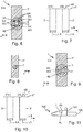
- Figs. 1 to 11 show a battery device 1 according to the invention for supplying an electrically driven processing device 101 with electrical drive power AL.
- the battery device 1 has at least one battery cell 2 and at least one cell contactor 5 ', 5 ".
- the battery cell 2 has a terminal 3 with a safety valve 4, as in FIG Fig. 1 shown.
- the safety valve 4 is with a moving part 4B of a surface 3O of the terminal 3 from a closed position CS, as in FIG Fig. 2 shown, for movement in the outward direction z in an open position OS, as in Fig. 3 shown, trained.
- the cell contactor 5 ′, 5 ′′ has an electrical contact with the terminal 3 by means of at least one material connection SV, as in FIG Figures 6, 7 shown on the left, 9 and 10 on the left. Furthermore, the cell contactor 5 ′, 5 ′′ permits the movement of the moving part 4B, as in FIG Fig. 7 shown on the right and 10 on the right.
- the battery cell 2 is a, in particular elongate, round cell 10.
- the terminal 3 is arranged on an end face 11 of the round cell 10.
- the moving part 4B is designed to move along a longitudinal axis LA of the round cell 10.
- the longitudinal axis of the round cell 10 is parallel to the outward direction z.
- the terminal 3 has a predetermined breaking point 8 between the moving part 4B and a non-moving part 3A of the surface 3O of the terminal 3 that is different from the moving part 4B, as in FIG Fig. 1 shown.
- the, in particular circular, moving part 4B is surrounded or enclosed by the, in particular ring-shaped, non-moving part 3A, in particular in the radial direction r.
- the radial direction r is orthogonal to the outward direction z or the longitudinal axis LA.
- the movement from the closed position CS into the open position OS is an unfolding.
- Terminal 3 is also a minus terminal 9.
- the battery cell 2 in the exemplary embodiments shown, the round cell 10, has a further terminal 13 with a further safety valve 14 on an opposite side 12, in particular the front side, as in FIG Fig. 4 shown.
- the further terminal 13 is a plus terminal 15.
- the battery cell 2 in the exemplary embodiments shown, the round cell 10, has a peripheral side 16 between the side 11, in particular the end face, and the side 12, in particular the end face.
- the battery cell 2 is designed for a maximum energy content MEI of 18 Wh.
- the battery cell can be designed for a maximum energy content of a minimum of 9 Wh and / or a maximum of 360 Wh.
- the battery cell 2 is a 21700 cell.
- the cell contactor 5 ′, 5 ′′ is designed in one piece and / or as a sheet metal.
- the cell contactor 5 ', 5 "and the terminal 3 in the closed position CS of the moving part 5B are secured against movement relative to one another by means of the at least one material connection SV, in particular in the outward direction z and / or the radial direction r.
- the at least one material connection SV is a welded connection WV.
- the cell contactor 5 ′ has the at least one material connection SV with the terminal 3 in the non-moving part 3A of the surface 3O of the terminal 3, which is different from the moving part 4B.
- the cell contactor 5 ′ is arranged outside a movement space BR of the moving part 4B, in particular in the radial direction r.
- the cell contactor 5 ′ has an in particular ring-shaped and / or closed valve recess 6 for the moving part 4B.
- a diameter of the valve recess 6 is greater than a diameter of the moving part 4B in the radial direction r.
- the cell contactor 5 'does not move the moving part 4B in the outward direction z or along the longitudinal axis LA.
- the cell contactor 5 ′′ has the at least one material connection SV with the terminal 3 in the moving part 4B. Furthermore, the cell contacting 5 ′′ is designed, in particular partially, to move with or open with the moving part 4B, in particular as a contact tongue 7.
- the contact tongue 7 has the at least one material connection SV with the terminal 3 in the moving part 4B '.
- the cell contactor 5 ′′ acts on the moving part 4B in the closed position CS with no force in the inward direction -z, and in particular with no force in the outward direction z.
- the cell contactor 5 'in the closed position CS of the moving part 4B with the terminal 3 makes electrical contact by means of four material connections SV.
- the cell contactor 5 ′′ in the closed position CS of the moving part 4B makes electrical contact with the terminal 3 by means of only a single material connection SV.
- the cell contactor can make electrical contact with the terminal by means of only one single, two , three, four or at least five material connections.
- the cell contactor 5 ′, 5 ′′ has no electrical contact with the terminal 3 in the open position OS of the moving part 4B.
- the battery device 1 has at least one, in particular the same, further battery cell 2 ', as in FIG Figures 7 and 10 shown.
- the battery cell 2 and the further battery cell 2 ' are electrically interconnected by means of the cell contactor 5', 5 ".
- the battery cell 2 and the further battery cell 2 ' are arranged next to one another, in particular with the longitudinal axes LA parallel to one another.
- the battery device can have only a single, two or at least three battery cells.
- the battery device can have only a single cell contactor or at least two cell contactors.
- the battery device 1 has a device or pack housing 20, as in FIG Fig. 11 shown.
- the at least one battery cell 2, and in particular the at least one further battery cell 2 ′, and the at least one cell contactor 5 ′, 5 ′′ are arranged in the device housing 20.
- Fig. 11 shows a processing system 100 according to the invention.
- the processing system has the battery device 1 and an electrically driven processing device 101.
- the battery device 1 and the processing device 101 are designed to be electrically connected to each other for supplying the processing device 101 with electrical drive power AL from the battery device 1, in particular electrically connected.
- the electrically driven processing device 101 is a saw 102.
- the processing device can be a pruner, a brush cutter, a hedge trimmer, a hedge cutter, a blower, a leaf blower, a pruning shears, a power cutter, a sweeper, a rotary brush, a sweeping brush, a lawn mower, a scarifier or a grass shear .
- the processing device 101 in particular the saw 102, is designed to carry the battery device 1, in particular to carry it.
- the invention provides a battery device for supplying an electrically driven processing device with electrical drive power, the battery device having improved properties, in particular being safer, and a processing system comprising such a battery device and an electrically driven processing device .
Landscapes
- Chemical & Material Sciences (AREA)
- Chemical Kinetics & Catalysis (AREA)
- Electrochemistry (AREA)
- General Chemical & Material Sciences (AREA)
- Inorganic Chemistry (AREA)
- Engineering & Computer Science (AREA)
- Manufacturing & Machinery (AREA)
- Connection Of Batteries Or Terminals (AREA)
- Gas Exhaust Devices For Batteries (AREA)
Abstract
Die Erfindung bezieht sich auf eine Batterievorrichtung (1) zur Versorgung eines elektrisch angetriebenen Bearbeitungsgeräts (101) mit elektrischer Antriebsleistung (AL), wobei die Batterievorrichtung (1) aufweist:- mindestens eine Batteriezelle (2), wobei die Batteriezelle (2) ein Terminal (3) mit einem Sicherheitsventil (4) aufweist, wobei das Sicherheitsventil (4) mit einem Bewegungsteil (4B) einer Oberfläche (3O) des Terminals (3) von einer Schließstellung (CS) zur Bewegung in Richtung nach außen (z) in eine Offenstellung (OS) ausgebildet ist, und- mindestens einen Zellkontaktierer (5', 5"), wobei der Zellkontaktierer (5', 5") in der Schließstellung (CS) des Bewegungsteils (4B) mit dem Terminal (3) einen elektrischen Kontakt mittels mindestens einer stoffschlüssigen Verbindung (SV) aufweist und die Bewegung des Bewegungsteils (4B) zulässt.The invention relates to a battery device (1) for supplying an electrically driven processing device (101) with electrical drive power (AL), the battery device (1) having: at least one battery cell (2), the battery cell (2) having a terminal (3) with a safety valve (4), the safety valve (4) having a moving part (4B) of a surface (3O) of the terminal (3) from a closed position (CS) to move outwards (z) into a Open position (OS) is formed, and at least one cell contactor (5 ', 5 "), the cell contactor (5', 5") making electrical contact with the terminal (3) in the closed position (CS) of the moving part (4B) has by means of at least one material connection (SV) and allows the movement of the moving part (4B).
Description
Die Erfindung bezieht sich auf eine Batterievorrichtung zur Versorgung eines elektrisch angetriebenen Bearbeitungsgeräts mit elektrischer Antriebsleistung und auf ein Bearbeitungssystem aufweisend eine solche Batterievorrichtung und ein elektrisch angetriebenes Bearbeitungsgerät.The invention relates to a battery device for supplying an electrically driven processing device with electrical drive power and to a processing system having such a battery device and an electrically driven processing device.
Der Erfindung liegt als Aufgabe die Bereitstellung einer Batterievorrichtung zur Versorgung eines elektrisch angetriebenen Bearbeitungsgeräts mit elektrischer Antriebsleistung, wobei die Batterievorrichtung, verbesserte Eigenschaften aufweist, insbesondere sicherer ist, und eines Bearbeitungssystems aufweisend eine solche Batterievorrichtung und ein elektrisch angetriebenes Bearbeitungsgerät zugrunde.The object of the invention is to provide a battery device for supplying an electrically driven processing device with electrical drive power, the battery device having improved properties, in particular being safer, and a processing system having such a battery device and an electrically driven processing device.
Die Erfindung löst die Aufgabe durch die Bereitstellung einer Batterievorrichtung mit den Merkmalen des Anspruchs 1 und eines Bearbeitungssystems mit den Merkmalen des Anspruchs 14. Vorteilhafte Weiterbildungen und/oder Ausgestaltungen der Erfindung sind in den abhängigen Ansprüchen beschrieben.The invention achieves the object by providing a battery device with the features of
Die erfindungsgemäße Batterievorrichtung ist zur, insbesondere automatischen, Versorgung eines elektrisch angetriebenen Bearbeitungsgeräts, insbesondere Garten-, Forst- und/oder Baubearbeitungsgeräts, mit elektrischer Antriebsleistung ausgebildet bzw. konfiguriert. Die Batterievorrichtung weist mindestens eine Batteriezelle und mindestens einen Zellkontaktierer auf. Die Batteriezelle weist ein Terminal mit einem Sicherheitsventil auf. Das Sicherheitsventil ist mit einem Bewegungsteil einer Oberfläche des Terminals von einer Schließstellung zur Bewegung bzw. zum Öffnen in Richtung nach außen in eine Offenstellung ausgebildet bzw. konfiguriert. Der Zellkontaktierer weist in der Schließstellung des Bewegungsteils mit dem Terminal, insbesondere direkt, einen elektrischen Kontakt bzw. eine elektrische Verbindung mittels mindestens einer stoffschlüssigen Verbindung auf. Des Weiteren lässt der Zellkontaktierer die Bewegung des Bewegungsteils, insbesondere von der Schließstellung in die Offenstellung, zu.The battery device according to the invention is designed or configured for the, in particular automatic, supply of an electrically driven processing device, in particular gardening, forestry and / or construction processing device, with electrical drive power. The battery device has at least one battery cell and at least one cell contactor. The battery cell has a terminal with a safety valve. The safety valve is formed or configured with a moving part of a surface of the terminal from a closed position to move or to open in an outward direction into an open position. In the closed position of the moving part with the terminal, the cell contactor has, in particular directly, an electrical contact or an electrical connection by means of at least one material connection. Furthermore, the cell contactor allows the moving part to move, in particular from the closed position to the open position.
Das Sicherheitsventil, insbesondere mit dem Bewegungsteil in der Offenstellung, ermöglicht ein Ablassen von Abgas von innen bzw. innerhalb der Batteriezelle nach außen bzw. außerhalb der Batteriezelle, insbesondere wenn ein Druck von Abgas erzeugt durch eine elektrochemische Reaktion stattfindend in bzw. innerhalb der Batteriezelle einen vorbestimmten Grenzdruck überschreitet. Dies kann ermöglichen, einen Schaden klein zu halten, insbesondere auch wenn die Batteriezelle einen relativ hohen Energieinhalt aufweisen kann.The safety valve, in particular with the moving part in the open position, enables exhaust gas to be discharged from the inside or inside the battery cell to the outside or outside the battery cell, in particular when a pressure of exhaust gas is generated by an electrochemical reaction taking place in or within the battery cell exceeds predetermined limit pressure. This can make it possible to keep damage to a minimum, in particular even if the battery cell can have a relatively high energy content.
Der Zellkontaktierer ermöglicht das Öffnen des Sicherheitsventils, insbesondere des Bewegungsteils. In anderen Worten: der Zellkontaktierer kann oder braucht das Sicherheitsventil nicht zuhalten.The cell contactor enables the safety valve, in particular the moving part, to be opened. In other words: the cell contactor cannot or does not need to close the safety valve.
Die stoffschlüssige Verbindung ermöglicht einen sicheren elektrischen Kontakt, insbesondere bei Korrosion des Terminals und/oder des Zellkontaktierers, z.B. im Unterschied zu einem elektrischen Kontakt mittels einer kraftschlüssigen Verbindung.The cohesive connection enables a secure electrical contact, especially in the event of corrosion of the terminal and / or the cell contactor, e.g. in contrast to an electrical contact by means of a non-positive connection.
Insbesondere kann die mindestens eine Batteriezelle zur Versorgung des Bearbeitungsgeräts mit Antriebsleistung ausgebildet sein. Zusätzlich oder alternativ kann die Batteriezelle entweder eine, insbesondere nicht wiederaufladbare, Primärzelle oder eine, insbesondere wiederaufladbare, Sekundärzelle bzw. Akkumulatorzelle sein. Insbesondere kann die Batteriezelle eine Lithium-Ionen-Akkumulatorzelle sein. Weiter zusätzlich oder alternativ kann das Terminal als Pol oder Elektrode bezeichnet werden. Weiter zusätzlich oder alternativ kann die Batteriezelle ein weiteres Terminal, insbesondere mit einem weiteren Sicherheitsventil, aufweisen. Insbesondere kann die Batterievorrichtung einen weiteren Zellkontaktierer aufweisen, wobei der weitere Zellkontaktierer mit dem weiteren Terminal einen elektrischen Kontakt aufweisen kann.In particular, the at least one battery cell can be designed to supply the machining device with drive power. Additionally or alternatively, the battery cell can either be a, in particular non-rechargeable, primary cell or a, in particular rechargeable, secondary cell or accumulator cell. In particular, the battery cell can be a lithium-ion accumulator cell. In addition or as an alternative, the terminal can also be referred to as a pole or electrode. Furthermore, additionally or alternatively, the battery cell can have a further terminal, in particular with a further safety valve. In particular, the battery device can have a further cell contactor, wherein the further cell contactor can have an electrical contact with the further terminal.
Die Oberfläche des Terminals kann eine Außenfläche sein. Zusätzlich oder alternativ können die Schließstellung und die Offenstellung verschieden sein. Insbesondere kann das Sicherheitsventil mit dem Bewegungsteil in der Schließstellung zum Verhindern eines Ablassens von Abgas von innen nach außen ausgebildet sein. Zusätzlich oder alternativ kann das Sicherheitsventil mit dem Bewegungsteil in der Offenstellung zum Zulassen eines Ablassens von Abgas von innen nach außen ausgebildet sein. Weiter zusätzlich oder alternativ kann das Sicherheitsventil mit dem Bewegungsteil von der Schließstellung zur Bewegung in die Offenstellung bei Überschreitung eines vorbestimmten Grenzdrucks durch einen Druck von Abgas in bzw. innerhalb der Batteriezelle ausgebildet sein. Weiter zusätzlich oder alternativ kann die Bewegung von der Schließstellung in die Offenstellung ein Aufklappen sein.The surface of the terminal can be an exterior surface. Additionally or alternatively, the closed position and the open position can be different. In particular, the safety valve with the moving part in the closed position can be designed to prevent exhaust gas from being released from the inside to the outside. Additionally or alternatively, the safety valve can be designed with the moving part in the open position to allow exhaust gas to be discharged from the inside to the outside. Furthermore, additionally or alternatively, the safety valve can be designed with the moving part from the closed position to the movement into the open position when a predetermined limit pressure is exceeded by exhaust gas pressure in or within the battery cell. Furthermore, additionally or alternatively, the movement from the closed position into the open position can be an opening.
Der Zellkontaktierer kann in der Offenstellung des Bewegungsteils mit dem Terminal keinen elektrischen Kontakt aufweisen. Anders formuliert: der Zellkontaktierer und/oder der Bewegungsteil können/kann zur Zerstörung der mindestens einen stoffschlüssigen Verbindung durch die Bewegung des Bewegungsteils von der Schließstellung in die Offenstellung ausgebildet sein.When the moving part is in the open position, the cell contactor cannot have any electrical contact with the terminal. In other words: the cell contactor and / or the moving part can be designed to destroy the at least one material connection by moving the moving part from the closed position into the open position.
In einer Weiterbildung der Erfindung ist die Batteriezelle für einen maximalen Energieinhalt von minimal 9 Wattstunden (Wh) und/oder von maximal 360 Wh ausgebildet bzw. konfiguriert. Dies kann ermöglichen, dass die Batteriezelle einen relativ hohen Energieinhalt aufweisen kann. Insbesondere kann die Batteriezelle für einen maximalen Energieinhalt von 5 Amperestunden mal 3,6 Volt = 18 Wh ausgebildet sein.In a further development of the invention, the battery cell is designed or configured for a maximum energy content of a minimum of 9 watt hours (Wh) and / or a maximum of 360 Wh. This can enable the battery cell to have a relatively high energy content. In particular, the battery cell can be designed for a maximum energy content of 5 ampere hours times 3.6 volts = 18 Wh.
In einer Weiterbildung der Erfindung sind der Zellkontaktierer und das Terminal in der Schließstellung des Bewegungsteils mittels der mindestens einen stoffschlüssigen Verbindung gegen Bewegung relativ zueinander gesichert. Dies ermöglicht einen sicheren elektrischen Kontakt, insbesondere bei Vibration des Terminals und/oder des Zellkontaktierers, z.B. im Unterschied zu einem elektrischen Kontakt mittels einer kraftschlüssigen Verbindung. Insbesondere kann der Zellkontaktierer in der Schließstellung des Bewegungsteils mit dem Terminal, insbesondere direkt, eine mechanische Verbindung mittels der mindestens einen stoffschlüssigen Verbindung aufweisen. Zusätzlich oder alternativ können oder brauchen der Zellkontaktierer und das Terminal in der Offenstellung des Bewegungsteils nicht gegen Bewegung relativ zueinander gesichert sein.In a development of the invention, the cell contactor and the terminal are secured against movement relative to one another in the closed position of the moving part by means of the at least one material connection. This enables safe electrical contact, in particular when the terminal and / or the cell contactor vibrates, e.g. in contrast to an electrical contact by means of a non-positive connection. In particular, in the closed position of the moving part with the terminal, in particular directly, the cell contactor can have a mechanical connection by means of the at least one material connection. Additionally or alternatively, the cell contactor and the terminal cannot or need not be secured against movement relative to one another in the open position of the moving part.
In einer Weiterbildung der Erfindung weist der Zellkontaktierer die mindestens eine stoffschlüssige Verbindung mit dem Terminal in einem von dem Bewegungsteil verschiedenen Nichtbewegungsteil der Oberfläche des Terminals auf. Dies ermöglicht, dass der Zellkontaktierer die Bewegung des Bewegungsteils zulässt.In a further development of the invention, the cell contactor has the at least one material connection with the terminal in a non-moving part of the surface of the terminal that is different from the moving part. This enables the cell contactor to allow the moving part to move.
In einer Ausgestaltung der Erfindung ist der Zellkontaktierer, insbesondere vollständig, außerhalb bzw. nicht innerhalb eines Bewegungsraums des Bewegungsteils bzw. nicht in dem Bewegungsraum angeordnet. Insbesondere weist der Zellkontaktierer eine Ventilaussparung für den Bewegungsteil auf. Insbesondere kann der Zellkontaktierer derart angeordnet sein, dass der Zellkontaktierer den Bewegungsteil in Richtung nach außen nicht bedecken kann. Zusätzlich oder alternativ kann der Bewegungsraum für die Bewegung des Bewegungsteils von der Schließstellung in die Offenstellung sein.In one embodiment of the invention, the cell contactor is arranged, in particular completely, outside or not within a movement space of the moving part or not in the movement space. In particular, the cell contactor has a valve recess for the moving part. In particular, the cell contactor can be arranged such that the cell contactor cannot cover the moving part in the outward direction. Additionally or alternatively, the movement space for moving the moving part from the closed position into the open position can be.
In einer Weiterbildung der Erfindung weist der Zellkontaktierer die mindestens eine stoffschlüssige Verbindung mit dem Terminal in dem Bewegungsteil auf. Des Weiteren ist der Zellkontaktierer, insbesondere teilweise, zur Mitbewegung mit dem Bewegungsteil, insbesondere als Kontaktzunge bzw. Kontaktstreifen, ausgebildet bzw. konfiguriert. Dies ermöglicht, dass der Zellkontaktierer die Bewegung des Bewegungsteils zulässt. Insbesondere kann die Kontaktzunge die mindestens eine stoffschlüssige Verbindung mit dem Terminal in dem Bewegungsteil aufweisen.In a further development of the invention, the cell contactor has the at least one material connection with the terminal in the moving part. Furthermore, the cell contactor is designed or configured, in particular partially, to move with the moving part, in particular as a contact tongue or contact strip. This enables the cell contactor to allow the moving part to move. In particular, the contact tongue can have the at least one material connection with the terminal in the moving part.
In einer Ausgestaltung der Erfindung beaufschlägt der Zellkontaktierer den Bewegungsteil in der Schließstellung mit keiner Kraft in Richtung nach innen. Dies ermöglicht eine Erhöhung des vorbestimmten Grenzdrucks, soweit vorhanden, zu vermeiden, z.B. im Unterschied zu einem elektrischen Kontakt mittels einer kraftschlüssigen Verbindung. Insbesondere kann oder braucht der Zellkontaktierer den Bewegungsteil in der Schließstellung mit keiner Kraft in Richtung nach außen beaufschlagen. In anderen Worten: der Zellkontaktierer kann auf dem Bewegungsteil liegen.In one embodiment of the invention, the cell contactor does not apply any inward force to the moving part in the closed position. This enables an increase in the predetermined limit pressure, if any, to be avoided, e.g. in contrast to an electrical contact by means of a non-positive connection. In particular, the cell contactor cannot or does not have to apply any force in the outward direction to the moving part in the closed position. In other words: the cell contactor can lie on the moving part.
Die mindestens eine stoffschlüssige Verbindung kann eine Lötverbindung sein.The at least one material connection can be a soldered connection.
In einer Weiterbildung der Erfindung ist die mindestens eine stoffschlüssige Verbindung eine Schweißverbindung.In a further development of the invention, the at least one material connection is a welded connection.
In einer Weiterbildung der Erfindung weist das Terminal zwischen dem Bewegungsteil und einem, insbesondere dem, von dem Bewegungsteil verschiedenen Nichtbewegungsteil der Oberfläche des Terminals eine Sollbruchstelle auf. Dies, insbesondere ein Brechen bzw. Versagen der Sollbruchstelle, ermöglicht die Bewegung des Bewegungsteils von der Schließstellung in die Offenstellung und/oder ein Vorbestimmen des Grenzdrucks, soweit vorhanden. Insbesondere kann die Sollbruchstelle eine Kerbe, eine Einritzung oder ein Prägung, insbesondere in dem Terminal, aufweisen oder sein.In a further development of the invention, the terminal has a predetermined breaking point between the moving part and a non-moving part of the surface of the terminal, in particular the non-moving part that is different from the moving part. This, in particular a breaking or failure of the predetermined breaking point, enables the movement of the moving part from the closed position to the open position and / or a pre-determination of the limit pressure, if any. In particular, the predetermined breaking point can have or be a notch, an incision or an embossing, in particular in the terminal.
In einer Weiterbildung der Erfindung ist das Terminal ein Minusterminal bzw. negatives Terminal.In a further development of the invention, the terminal is a minus terminal or negative terminal.
Insbesondere kann die Batteriezelle eine prismatische Zelle sein.In particular, the battery cell can be a prismatic cell.
In einer Weiterbildung der Erfindung ist die Batteriezelle eine, insbesondere längliche, Rundzelle. Das Terminal ist an einer Stirnseite der Rundzelle angeordnet. Der Bewegungsteil ist zur Bewegung entlang einer Längsachse der Rundzelle ausgebildet bzw. konfiguriert. Insbesondere kann eine Länge der Rundzelle größer als ein Durchmesser der Rundzelle sein. Zusätzlich oder alternativ kann die Rundzelle an einer gegenüberliegenden Stirnseite ein weiteres, insbesondere das weitere, Terminal aufweisen.In a further development of the invention, the battery cell is a, in particular elongated, round cell. The terminal is arranged on one end of the round cell. The moving part is designed or configured for movement along a longitudinal axis of the round cell. In particular, a length of the round cell can be greater than a diameter of the round cell. Additionally or alternatively, the round cell can have a further, in particular the further, terminal on an opposite end face.
In einer Weiterbildung der Erfindung ist das Terminal an einer Seite, insbesondere der Stirnseite, der Batteriezelle angeordnet. Die Batteriezelle weist an einer gegenüberliegenden Seite, insbesondere Stirnseite, ein weiteres, insbesondere das weitere, Terminal mit einem, insbesondere dem, weiteren Sicherheitsventil auf. Dies kann ermöglichen, einen Schaden klein zu halten, insbesondere auch wenn die Batteriezelle einen besonders hohen Energieinhalt aufweisen kann.In a further development of the invention, the terminal is arranged on one side, in particular the end face, of the battery cell. On an opposite side, in particular the end face, the battery cell has a further, in particular the further, terminal with a, in particular the, further safety valve. This can make it possible to keep damage to a minimum, especially if the battery cell can have a particularly high energy content.
In einer Weiterbildung der Erfindung weist die Batterievorrichtung mindestens eine weitere Batteriezelle auf. Die Batteriezelle und die weitere Batteriezelle sind mittels des Zellkontaktierers elektrisch zusammengeschaltet. Insbesondere kann die Batterievorrichtung als Batteriepack bezeichnet werden. Zusätzlich oder alternativ können die Batteriezelle und die weitere Batteriezelle gleich, insbesondere typ- und/oder baugleich, sein. Weiter zusätzlich oder alternativ können die Batteriezelle und die weitere Batteriezelle mittels des Zellkontaktierers seriell oder parallel geschaltet sein.In a further development of the invention, the battery device has at least one further battery cell. The battery cell and the further battery cell are electrically interconnected by means of the cell contactor. In particular, the battery device can be referred to as a battery pack. Additionally or alternatively, the battery cell and the further battery cell can be of the same type, in particular of the same type and / or construction. Furthermore, additionally or alternatively, the battery cell and the further battery cell can be connected in series or in parallel by means of the cell contactor.
Das erfindungsgemäße Bearbeitungssystem weist eine, insbesondere die, Batterievorrichtung wie zuvor beschrieben und ein, insbesondere das, elektrisch angetriebenes Bearbeitungsgerät auf. Die Batterievorrichtung und das Bearbeitungsgerät sind zur elektrischen Verbindung miteinander zur, insbesondere automatischen, Versorgung des Bearbeitungsgeräts mit elektrischer Antriebsleistung von der Batterievorrichtung ausgebildet bzw. konfiguriert.The processing system according to the invention has one, in particular the battery device as described above, and one, in particular the, electrically driven processing device. The battery device and the processing device are designed or configured for electrical connection to one another for, in particular automatically, supplying the processing device with electrical drive power from the battery device.
Insbesondere kann das Bearbeitungssystem ein Garten-, Forst- und/oder Baubearbeitungssystem sein. Zusätzlich oder alternativ kann das Bearbeitungsgerät ein Garten-, Forst- und/oder Baubearbeitungsgerät sein. Weiter zusätzlich oder alternativ kann das Bearbeitungsgerät ein handgeführtes, insbesondere bodengeführtes oder handgetragenes, Bearbeitungsgerät sein. Insbesondere handgeführtes, insbesondere handgetragenes, Bearbeitungsgerät kann bedeuten, dass das Bearbeitungsgerät eine maximale Masse von 50 Kilogramm (kg), insbesondere von 20 kg, insbesondere von 10 kg, aufweisen kann. Weiter zusätzlich oder alternativ kann das Bearbeitungsgerät einen Elektroantriebsmotor aufweisen. Weiter zusätzlich oder alternativ können die Batterievorrichtung und das Bearbeitungsgerät zur, insbesondere werkzeugfrei und/oder zerstörungsfrei, lösbaren elektrischen Verbindung miteinander ausgebildet sein, insbesondere mittels Steckverbinder. Weiter zusätzlich oder alternativ können die Batterievorrichtung und das Bearbeitungsgerät zur, insbesondere lösbaren, insbesondere werkzeugfrei und/oder zerstörungsfrei lösbaren, mechanischen Verbindung miteinander ausgebildet sein. Insbesondere kann das Bearbeitungsgerät zum Tragen der Batterievorrichtung ausgebildet sein.In particular, the processing system can be a garden, forest and / or construction processing system. Additionally or alternatively, the processing device can be a garden, forest and / or construction processing device. Furthermore, additionally or alternatively, the processing device can be a hand-held, in particular floor-mounted or hand-carried, processing device. In particular, a hand-held, in particular hand-carried, processing device can mean that the processing device can have a maximum mass of 50 kilograms (kg), in particular 20 kg, in particular 10 kg. Furthermore, additionally or alternatively, the processing device can have an electric drive motor. Furthermore, additionally or alternatively, the battery device and the processing device can be used for a detachable electrical connection, in particular without tools and / or non-destructively be formed with each other, in particular by means of connectors. Furthermore, additionally or alternatively, the battery device and the processing device can be designed for, in particular, a releasable, in particular tool-free and / or non-destructively releasable mechanical connection to one another. In particular, the processing device can be designed to carry the battery device.
In einer Weiterbildung der Erfindung ist das elektrisch angetriebene Bearbeitungsgerät eine Säge, ein Hoch-Entaster, ein Freischneider, eine Heckenschere, ein Heckenschneider, ein Blasgerät, ein Laubbläser, eine Astschere, ein Trennschleifer, ein Kehrgerät, eine Kehrwalze, eine Kehrbürste, ein Rasenmäher, ein Vertikutierer oder eine Grasschere.In a further development of the invention, the electrically driven processing device is a saw, a pruner, a brush cutter, a hedge trimmer, a hedge cutter, a blower, a leaf blower, a pruner, a power cutter, a sweeper, a roller broom, a sweeping brush, a lawn mower , a scarifier or grass shears.
Weitere Vorteile und Aspekte der Erfindung ergeben sich aus den Ansprüchen und aus der nachfolgenden Beschreibung von bevorzugten Ausführungsbeispielen der Erfindung, die nachfolgend anhand der Figuren erläutert sind. Dabei zeigen:
- Fig. 1
- eine schematische Ansicht auf eine Stirnseite einer Batteriezelle mit einem Sicherheitsventil mit einem Bewegungsteil in einer Schließstellung einer erfindungsgemäßen Batterievorrichtung,
- Fig. 2
- eine schematische Ansicht auf eine Umfangsseite der Batteriezelle der
Fig. 1 mit dem Bewegungsteil in der Schließstellung, - Fig. 3
- eine schematische Ansicht auf die Umfangsseite der Batteriezelle der
Fig. 1 mit dem Bewegungsteil in einer Offenstellung, - Fig. 4
- eine schematische Ansicht auf eine gegenüberliegenden Stirnseite der Batteriezelle der
Fig. 1 mit einem weiteren Sicherheitsventil, - Fig. 5
- eine schematische Ansicht auf ein erstes Ausführungsbeispiels eines Zellkontaktierers der erfindungsgemäßen Batterievorrichtung,
- Fig. 6
- eine schematische Ansicht auf die Stirnseite der Batteriezelle der
Fig. 1 mit dem Bewegungsteil in der Schließstellung und den Zellkontaktierer derFig. 5 , - Fig. 7
- eine schematische Ansicht auf die Umfangsseite der Batteriezelle der
Fig. 1 mit dem Bewegungsteil in der Schließstellung, eine Umfangsseite einer weiteren Batteriezelle mit einem Bewegungsteil in der Offenstellung und den Zellkontaktierer derFig. 5 , - Fig. 8
- eine schematische Ansicht auf ein zweites Ausführungsbeispiels eines Zellkontaktierers der erfindungsgemäßen Batterievorrichtung,
- Fig. 9
- eine schematische Ansicht auf die Stirnseite der Batteriezelle der
Fig. 1 mit dem Bewegungsteil in der Schließstellung und den Zellkontaktierer derFig. 8 , - Fig. 10
- eine schematische Ansicht auf die Umfangsseite der Batteriezelle der
Fig. 1 mit dem Bewegungsteil in der Schließstellung, eine Umfangsseite einer weiteren Batteriezelle mit einem Bewegungsteil in der Offenstellung und den Zellkontaktierer derFig. 8 , und - Fig. 11
- eine schematische Ansicht auf ein erfindungsgemäßes Bearbeitungssystem aufweisend die erfindungsgemäße Batterievorrichtung der
Fig. 1 und ein elektrisch angetriebenes Bearbeitungsgerät in Form einer Säge.bis 10
- Fig. 1
- a schematic view of an end face of a battery cell with a safety valve with a moving part in a closed position of a battery device according to the invention,
- Fig. 2
- a schematic view of a peripheral side of the battery cell of FIG
Fig. 1 with the moving part in the closed position, - Fig. 3
- a schematic view of the peripheral side of the battery cell of FIG
Fig. 1 with the moving part in an open position, - Fig. 4
- a schematic view of an opposite end face of the battery cell of FIG
Fig. 1 with another safety valve, - Fig. 5
- a schematic view of a first embodiment of a cell contactor of the battery device according to the invention,
- Fig. 6
- a schematic view of the end face of the battery cell of FIG
Fig. 1 with the moving part in the closed position and the cell contactorFig. 5 , - Fig. 7
- a schematic view of the peripheral side of the battery cell of FIG
Fig. 1 with the moving part in the closed position, a peripheral side of a further battery cell with a moving part in the open position and the cell contactor of theFig. 5 , - Fig. 8
- a schematic view of a second embodiment of a cell contactor of the battery device according to the invention,
- Fig. 9
- a schematic view of the end face of the battery cell of FIG
Fig. 1 with the moving part in the closed position and the cell contactorFig. 8 , - Fig. 10
- a schematic view of the peripheral side of the battery cell of FIG
Fig. 1 with the moving part in the closed position, a peripheral side of a further battery cell with a moving part in the open position and the cell contactor of theFig. 8 , and - Fig. 11
- a schematic view of a processing system according to the invention having the battery device according to the invention from FIG
Figs. 1 to 10 and an electrically powered processing device in the form of a saw.
In den gezeigten Ausführungsbeispielen ist die Batteriezelle 2 eine, insbesondere längliche, Rundzelle 10. Das Terminal 3 ist an einer Stirnseite 11 der Rundzelle 10 angeordnet. Der Bewegungsteil 4B ist zur Bewegung entlang einer Längsachse LA der Rundzelle10 ausgebildet.In the exemplary embodiments shown, the
In den gezeigten Ausführungsbeispielen ist die Längsachse der Rundzelle 10 parallel zu der Richtung nach außen z.In the embodiments shown, the longitudinal axis of the
Des Weiteren weist das Terminal 3 zwischen dem Bewegungsteil 4B und einem von dem Bewegungsteil 4B verschiedenen Nichtbewegungsteil 3A der Oberfläche 3O des Terminals 3 eine Sollbruchstelle 8 auf, wie in
In den gezeigten Ausführungsbeispielen ist der, insbesondere kreisrunde, Bewegungsteil 4B von dem, insbesondere ringförmigen, Nichtbewegungsteil 3A umgeben bzw. umschlossen, insbesondere in radialer Richtung r. Insbesondere ist die radiale Richtung r orthogonal zu der Richtung nach außen z bzw. der Längsachse LA.In the exemplary embodiments shown, the, in particular circular, moving
Außerdem ist in den gezeigten Ausführungsbeispielen die Bewegung von der Schließstellung CS in die Offenstellung OS ein Aufklappen.In addition, in the exemplary embodiments shown, the movement from the closed position CS into the open position OS is an unfolding.
Weiter ist das Terminal 3 ein Minusterminal 9.Terminal 3 is also a
Zudem weist die Batteriezelle 2, in den gezeigten Ausführungsbeispielen die Rundzelle 10, an einer gegenüberliegenden Seite 12, insbesondere Stirnseite, ein weiteres Terminal 13 mit einem weiteren Sicherheitsventil 14 auf, wie in
Insbesondere ist das weitere Terminal 13 ein Plusterminal 15.In particular, the
Des Weiteren weist die Batteriezelle 2, in den gezeigten Ausführungsbeispielen die Rundzelle 10, zwischen der Seite 11, insbesondere Stirnseite, und der Seite 12, insbesondere Stirnseite, eine Umfangsseite 16 auf.Furthermore, the
Außerdem ist die Batteriezelle 2 für einen maximalen Energieinhalt MEI von 18 Wh ausgebildet. In alternativen Ausführungsbeispielen kann die Batteriezelle für einen maximalen Energieinhalt von minimal 9 Wh und/oder von maximal 360 Wh ausgebildet sein.In addition, the
Im Detail ist die Batteriezelle 2 eine 21700-Zelle.In detail, the
Weiter ist in den gezeigten Ausführungsbeispielen der Zellkontaktierer 5', 5" einstückig und/oder als Blech ausgebildet.Furthermore, in the exemplary embodiments shown, the
Zudem sind der Zellkontaktierer 5', 5" und das Terminal 3 in der Schließstellung CS des Bewegungsteils 5B mittels der mindestens einen stoffschlüssigen Verbindung SV gegen Bewegung relativ zueinander gesichert, insbesondere in der Richtung nach außen z und/oder der radialen Richtung r.In addition, the
Des Weiteren ist die mindestens eine stoffschlüssige Verbindung SV eine Schweißverbindung WV.Furthermore, the at least one material connection SV is a welded connection WV.
In dem Ausführungsbeispiel der
Im Detail ist der Zellkontaktierer 5' außerhalb eines Bewegungsraums BR des Bewegungsteils 4B angeordnet, insbesondere in radialer Richtung r. Insbesondere weist der Zellkontaktierer 5' eine, insbesondere ringförmige und/oder geschlossene, Ventilaussparung 6 für den Bewegungsteil 4B auf.In detail, the
In dem Ausführungsbeispiel der
Außerdem bedeckt in dem Ausführungsbeispiel der
In dem Ausführungsbeispiel der
Insbesondere weist die Kontaktzunge 7 die mindestens eine stoffschlüssige Verbindung SV mit dem Terminal 3 in dem Bewegungsteil 4B auf'.In particular, the
Im Detail beaufschlägt der Zellkontaktierer 5" den Bewegungsteil 4B in der Schließstellung CS mit keiner Kraft in Richtung nach innen -z, und insbesondere mit keiner Kraft in Richtung nach außen z.In detail, the
Zudem weist in dem Ausführungsbeispiel der
Außerdem weist in den gezeigten Ausführungsbeispielen der Zellkontaktierer 5', 5" in der Offenstellung OS des Bewegungsteils 4B mit dem Terminal 3 keinen elektrischen Kontakt auf.In addition, in the exemplary embodiments shown, the
Weiter weist die Batterievorrichtung 1 mindestens eine, insbesondere gleiche, weitere Batteriezelle 2' auf, wie in
Im Detail sind die Batteriezelle 2 und die weitere Batteriezelle 2' nebeneinander angeordnet, insbesondere mit den Längsachsen LA parallel zueinander.In detail, the
In alternativen Ausführungsbeispielen kann die Batterievorrichtung nur eine einzige, zwei oder mindestens drei Batteriezellen aufweisen.In alternative exemplary embodiments, the battery device can have only a single, two or at least three battery cells.
Zudem kann in alternativen Ausführungsbeispielen die Batterievorrichtung nur eine einzige oder mindestens zwei Zellkontaktierer aufweisen.In addition, in alternative exemplary embodiments, the battery device can have only a single cell contactor or at least two cell contactors.
Des Weiteren weist die Batterievorrichtung 1 ein Vorrichtungs- bzw. Packgehäuse 20 auf, wie in
In
In
Wie die gezeigten und oben erläuterten Ausführungsbeispiele deutlich machen, stellt die Erfindung eine Batterievorrichtung zur Versorgung eines elektrisch angetriebenen Bearbeitungsgeräts mit elektrischer Antriebsleistung, wobei die Batterievorrichtung, verbesserte Eigenschaften aufweist, insbesondere sicherer ist, und ein Bearbeitungssystem aufweisend eine solche Batterievorrichtung und ein elektrisch angetriebenes Bearbeitungsgerät bereit.As the exemplary embodiments shown and explained above make clear, the invention provides a battery device for supplying an electrically driven processing device with electrical drive power, the battery device having improved properties, in particular being safer, and a processing system comprising such a battery device and an electrically driven processing device .
Claims (15)
Priority Applications (3)
| Application Number | Priority Date | Filing Date | Title |
|---|---|---|---|
| EP19174310.3A EP3739663A1 (en) | 2019-05-14 | 2019-05-14 | Battery device and processing system |
| US15/931,205 US20200365869A1 (en) | 2019-05-14 | 2020-05-13 | Battery Apparatus and Work System |
| CN202010407687.6A CN111952512A (en) | 2019-05-14 | 2020-05-14 | Battery device and processing system |
Applications Claiming Priority (1)
| Application Number | Priority Date | Filing Date | Title |
|---|---|---|---|
| EP19174310.3A EP3739663A1 (en) | 2019-05-14 | 2019-05-14 | Battery device and processing system |
Publications (1)
| Publication Number | Publication Date |
|---|---|
| EP3739663A1 true EP3739663A1 (en) | 2020-11-18 |
Family
ID=66542094
Family Applications (1)
| Application Number | Title | Priority Date | Filing Date |
|---|---|---|---|
| EP19174310.3A Pending EP3739663A1 (en) | 2019-05-14 | 2019-05-14 | Battery device and processing system |
Country Status (3)
| Country | Link |
|---|---|
| US (1) | US20200365869A1 (en) |
| EP (1) | EP3739663A1 (en) |
| CN (1) | CN111952512A (en) |
Citations (3)
| Publication number | Priority date | Publication date | Assignee | Title |
|---|---|---|---|---|
| DE69305061T2 (en) * | 1992-12-22 | 1997-02-27 | Honda Motor Co Ltd | Battery with rust-proof structure |
| US20110123845A1 (en) * | 2009-05-25 | 2011-05-26 | Kazuyuki Kusama | Battery pack, vehicle equipped with the battery pack, and device equipped with the battery pack |
| EP3444865A1 (en) * | 2017-08-16 | 2019-02-20 | Robert Bosch GmbH | Batterymodule and car with battery module |
Family Cites Families (14)
| Publication number | Priority date | Publication date | Assignee | Title |
|---|---|---|---|---|
| JP3312853B2 (en) * | 1996-09-26 | 2002-08-12 | 松下電器産業株式会社 | Battery connection structure |
| JP5436850B2 (en) * | 2008-12-19 | 2014-03-05 | 株式会社マキタ | Power tool battery pack |
| US20110117408A1 (en) * | 2009-11-13 | 2011-05-19 | Lennox Stuart B | Battery Assembly |
| JP2012195219A (en) * | 2011-03-17 | 2012-10-11 | Chuo Spring Co Ltd | Safety valve and battery provided with safety valve |
| DE102012202623A1 (en) * | 2012-02-21 | 2013-08-22 | Elringklinger Ag | cell connectors |
| WO2016009586A1 (en) * | 2014-07-15 | 2016-01-21 | 三洋電機株式会社 | Electricity storage device |
| DE102014019416A1 (en) * | 2014-12-20 | 2016-06-23 | Daimler Ag | Cell connector, cell connection unit and battery with a cell connection unit |
| DE102015007134A1 (en) * | 2015-06-05 | 2016-12-08 | Li-Tec Battery Gmbh | Single cell and electrochemical energy storage |
| DE102015219508A1 (en) * | 2015-10-08 | 2017-04-13 | Robert Bosch Gmbh | Safety device for increasing safety when using battery systems |
| JP2017152172A (en) * | 2016-02-24 | 2017-08-31 | トヨタ自動車株式会社 | Battery module |
| JP6968792B2 (en) * | 2016-06-30 | 2021-11-17 | 三洋電機株式会社 | Battery block |
| US10074846B2 (en) * | 2016-09-16 | 2018-09-11 | Nio Usa, Inc. | Battery module including a weldless busbar having an integrated fusible link |
| DE102017211006A1 (en) * | 2017-06-29 | 2019-01-03 | Robert Bosch Gmbh | Portable charging device |
| DE202018106375U1 (en) * | 2018-11-09 | 2018-11-15 | Lisa Dräxlmaier GmbH | Cell connector for electrically conductive connection of round cells of a battery for a motor vehicle and corresponding battery |
-
2019
- 2019-05-14 EP EP19174310.3A patent/EP3739663A1/en active Pending
-
2020
- 2020-05-13 US US15/931,205 patent/US20200365869A1/en active Pending
- 2020-05-14 CN CN202010407687.6A patent/CN111952512A/en active Pending
Patent Citations (3)
| Publication number | Priority date | Publication date | Assignee | Title |
|---|---|---|---|---|
| DE69305061T2 (en) * | 1992-12-22 | 1997-02-27 | Honda Motor Co Ltd | Battery with rust-proof structure |
| US20110123845A1 (en) * | 2009-05-25 | 2011-05-26 | Kazuyuki Kusama | Battery pack, vehicle equipped with the battery pack, and device equipped with the battery pack |
| EP3444865A1 (en) * | 2017-08-16 | 2019-02-20 | Robert Bosch GmbH | Batterymodule and car with battery module |
Also Published As
| Publication number | Publication date |
|---|---|
| US20200365869A1 (en) | 2020-11-19 |
| CN111952512A (en) | 2020-11-17 |
Similar Documents
| Publication | Publication Date | Title |
|---|---|---|
| EP1844646B1 (en) | Hedge shears | |
| EP2223782B1 (en) | Battery pack for an electrical tool | |
| EP2223781B1 (en) | Battery-operated, hand-held work device | |
| EP2224512A2 (en) | Battery pack for a hand-held work device | |
| EP2607026B1 (en) | Electric tool with an electric consumer and a battery pack | |
| DE102012005120A1 (en) | Connection system for an energy storage device and energy storage device with the connection system | |
| EP2223780A2 (en) | Electric work device with a battery pack | |
| EP2819207B1 (en) | Combination of a support system, battery and driven device | |
| DE202013102567U1 (en) | Mobile electrical device with at least two lithium-ion batteries and arrangement of two such electrically connected in series accumulators | |
| DE112012006185B4 (en) | Battery pack | |
| EP3678214B1 (en) | Structure, battery pack and gardening and/or forestry system | |
| EP3739663A1 (en) | Battery device and processing system | |
| EP3678216B1 (en) | Battery pack and gardening and/or forestry system | |
| EP3982473A1 (en) | Battery pack, processing system and method for producing a battery pack | |
| EP3678215B1 (en) | Cell connector structure, battery pack and gardening and/or forestry system | |
| EP3736876A1 (en) | Battery pack, processing system and method for producing a battery pack | |
| EP2469622B1 (en) | Pivotating connection for batteries | |
| EP4327396A1 (en) | Battery receiving system | |
| DE102021214995A1 (en) | Electrical device with a plurality of electromechanical battery interfaces | |
| EP3236513A1 (en) | Electrode assembly for a battery cell | |
| EP3082179A1 (en) | Battery with electric pneumo safety switch | |
| EP4030528A1 (en) | Battery pack, system and use of a battery pack | |
| EP2612381B1 (en) | Housing for accommodating at least one rechargeable battery cell | |
| WO2023180110A1 (en) | Accumulator pack, system comprising the accumulator pack, and an electrically powered tool and method for producing the accumulator pack | |
| EP4068484A1 (en) | Battery device and system |
Legal Events
| Date | Code | Title | Description |
|---|---|---|---|
| PUAI | Public reference made under article 153(3) epc to a published international application that has entered the european phase |
Free format text: ORIGINAL CODE: 0009012 |
|
| STAA | Information on the status of an ep patent application or granted ep patent |
Free format text: STATUS: THE APPLICATION HAS BEEN PUBLISHED |
|
| AK | Designated contracting states |
Kind code of ref document: A1 Designated state(s): AL AT BE BG CH CY CZ DE DK EE ES FI FR GB GR HR HU IE IS IT LI LT LU LV MC MK MT NL NO PL PT RO RS SE SI SK SM TR |
|
| AX | Request for extension of the european patent |
Extension state: BA ME |
|
| STAA | Information on the status of an ep patent application or granted ep patent |
Free format text: STATUS: REQUEST FOR EXAMINATION WAS MADE |
|
| 17P | Request for examination filed |
Effective date: 20210505 |
|
| RBV | Designated contracting states (corrected) |
Designated state(s): AL AT BE BG CH CY CZ DE DK EE ES FI FR GB GR HR HU IE IS IT LI LT LU LV MC MK MT NL NO PL PT RO RS SE SI SK SM TR |