EP3739660A1 - Battery module for a motor vehicle - Google Patents
Battery module for a motor vehicle Download PDFInfo
- Publication number
- EP3739660A1 EP3739660A1 EP20174185.7A EP20174185A EP3739660A1 EP 3739660 A1 EP3739660 A1 EP 3739660A1 EP 20174185 A EP20174185 A EP 20174185A EP 3739660 A1 EP3739660 A1 EP 3739660A1
- Authority
- EP
- European Patent Office
- Prior art keywords
- cell
- battery
- battery module
- carrier
- screwed
- Prior art date
- Legal status (The legal status is an assumption and is not a legal conclusion. Google has not performed a legal analysis and makes no representation as to the accuracy of the status listed.)
- Granted
Links
- 239000002826 coolant Substances 0.000 claims description 18
- 239000004020 conductor Substances 0.000 claims description 6
- 239000012782 phase change material Substances 0.000 claims description 6
- 230000007704 transition Effects 0.000 claims description 5
- 239000000463 material Substances 0.000 claims description 4
- 239000007787 solid Substances 0.000 claims description 3
- 238000004519 manufacturing process Methods 0.000 description 9
- HBBGRARXTFLTSG-UHFFFAOYSA-N Lithium ion Chemical compound [Li+] HBBGRARXTFLTSG-UHFFFAOYSA-N 0.000 description 4
- 229910001416 lithium ion Inorganic materials 0.000 description 4
- 239000011159 matrix material Substances 0.000 description 4
- 239000004743 Polypropylene Substances 0.000 description 3
- 230000008859 change Effects 0.000 description 3
- 150000001875 compounds Chemical class 0.000 description 3
- 238000011161 development Methods 0.000 description 3
- 230000018109 developmental process Effects 0.000 description 3
- 238000010438 heat treatment Methods 0.000 description 3
- 238000009434 installation Methods 0.000 description 3
- 238000012423 maintenance Methods 0.000 description 3
- 238000004382 potting Methods 0.000 description 3
- 238000004064 recycling Methods 0.000 description 3
- 230000008439 repair process Effects 0.000 description 3
- XECAHXYUAAWDEL-UHFFFAOYSA-N acrylonitrile butadiene styrene Chemical compound C=CC=C.C=CC#N.C=CC1=CC=CC=C1 XECAHXYUAAWDEL-UHFFFAOYSA-N 0.000 description 2
- 229920000122 acrylonitrile butadiene styrene Polymers 0.000 description 2
- 239000004676 acrylonitrile butadiene styrene Substances 0.000 description 2
- 239000012876 carrier material Substances 0.000 description 2
- 238000005266 casting Methods 0.000 description 2
- 230000000295 complement effect Effects 0.000 description 2
- 238000001816 cooling Methods 0.000 description 2
- 230000007850 degeneration Effects 0.000 description 2
- 238000005338 heat storage Methods 0.000 description 2
- 238000005304 joining Methods 0.000 description 2
- 239000004033 plastic Substances 0.000 description 2
- 229920003023 plastic Polymers 0.000 description 2
- 230000035939 shock Effects 0.000 description 2
- RYGMFSIKBFXOCR-UHFFFAOYSA-N Copper Chemical compound [Cu] RYGMFSIKBFXOCR-UHFFFAOYSA-N 0.000 description 1
- 239000000654 additive Substances 0.000 description 1
- 230000000996 additive effect Effects 0.000 description 1
- 229910052782 aluminium Inorganic materials 0.000 description 1
- XAGFODPZIPBFFR-UHFFFAOYSA-N aluminium Chemical compound [Al] XAGFODPZIPBFFR-UHFFFAOYSA-N 0.000 description 1
- 229910052802 copper Inorganic materials 0.000 description 1
- 239000010949 copper Substances 0.000 description 1
- 238000005520 cutting process Methods 0.000 description 1
- 230000007423 decrease Effects 0.000 description 1
- 230000001419 dependent effect Effects 0.000 description 1
- 238000013461 design Methods 0.000 description 1
- 238000003487 electrochemical reaction Methods 0.000 description 1
- 239000012530 fluid Substances 0.000 description 1
- 239000003365 glass fiber Substances 0.000 description 1
- 238000003754 machining Methods 0.000 description 1
- 229910052751 metal Inorganic materials 0.000 description 1
- 239000002184 metal Substances 0.000 description 1
- 238000000034 method Methods 0.000 description 1
- 239000012811 non-conductive material Substances 0.000 description 1
- -1 polypropylene Polymers 0.000 description 1
- 229920001155 polypropylene Polymers 0.000 description 1
- 230000008569 process Effects 0.000 description 1
- 238000012545 processing Methods 0.000 description 1
- 230000002787 reinforcement Effects 0.000 description 1
- 239000011347 resin Substances 0.000 description 1
- 229920005989 resin Polymers 0.000 description 1
- 239000011343 solid material Substances 0.000 description 1
- 239000000126 substance Substances 0.000 description 1
- 238000003466 welding Methods 0.000 description 1
- 238000009736 wetting Methods 0.000 description 1
Images
Classifications
-
- H—ELECTRICITY
- H01—ELECTRIC ELEMENTS
- H01M—PROCESSES OR MEANS, e.g. BATTERIES, FOR THE DIRECT CONVERSION OF CHEMICAL ENERGY INTO ELECTRICAL ENERGY
- H01M10/00—Secondary cells; Manufacture thereof
- H01M10/04—Construction or manufacture in general
- H01M10/0422—Cells or battery with cylindrical casing
-
- H—ELECTRICITY
- H01—ELECTRIC ELEMENTS
- H01M—PROCESSES OR MEANS, e.g. BATTERIES, FOR THE DIRECT CONVERSION OF CHEMICAL ENERGY INTO ELECTRICAL ENERGY
- H01M10/00—Secondary cells; Manufacture thereof
- H01M10/05—Accumulators with non-aqueous electrolyte
- H01M10/052—Li-accumulators
- H01M10/0525—Rocking-chair batteries, i.e. batteries with lithium insertion or intercalation in both electrodes; Lithium-ion batteries
-
- B—PERFORMING OPERATIONS; TRANSPORTING
- B60—VEHICLES IN GENERAL
- B60L—PROPULSION OF ELECTRICALLY-PROPELLED VEHICLES; SUPPLYING ELECTRIC POWER FOR AUXILIARY EQUIPMENT OF ELECTRICALLY-PROPELLED VEHICLES; ELECTRODYNAMIC BRAKE SYSTEMS FOR VEHICLES IN GENERAL; MAGNETIC SUSPENSION OR LEVITATION FOR VEHICLES; MONITORING OPERATING VARIABLES OF ELECTRICALLY-PROPELLED VEHICLES; ELECTRIC SAFETY DEVICES FOR ELECTRICALLY-PROPELLED VEHICLES
- B60L50/00—Electric propulsion with power supplied within the vehicle
- B60L50/50—Electric propulsion with power supplied within the vehicle using propulsion power supplied by batteries or fuel cells
- B60L50/60—Electric propulsion with power supplied within the vehicle using propulsion power supplied by batteries or fuel cells using power supplied by batteries
-
- H—ELECTRICITY
- H01—ELECTRIC ELEMENTS
- H01M—PROCESSES OR MEANS, e.g. BATTERIES, FOR THE DIRECT CONVERSION OF CHEMICAL ENERGY INTO ELECTRICAL ENERGY
- H01M10/00—Secondary cells; Manufacture thereof
- H01M10/60—Heating or cooling; Temperature control
- H01M10/61—Types of temperature control
- H01M10/613—Cooling or keeping cold
-
- H—ELECTRICITY
- H01—ELECTRIC ELEMENTS
- H01M—PROCESSES OR MEANS, e.g. BATTERIES, FOR THE DIRECT CONVERSION OF CHEMICAL ENERGY INTO ELECTRICAL ENERGY
- H01M10/00—Secondary cells; Manufacture thereof
- H01M10/60—Heating or cooling; Temperature control
- H01M10/62—Heating or cooling; Temperature control specially adapted for specific applications
- H01M10/625—Vehicles
-
- H—ELECTRICITY
- H01—ELECTRIC ELEMENTS
- H01M—PROCESSES OR MEANS, e.g. BATTERIES, FOR THE DIRECT CONVERSION OF CHEMICAL ENERGY INTO ELECTRICAL ENERGY
- H01M10/00—Secondary cells; Manufacture thereof
- H01M10/60—Heating or cooling; Temperature control
- H01M10/64—Heating or cooling; Temperature control characterised by the shape of the cells
- H01M10/643—Cylindrical cells
-
- H—ELECTRICITY
- H01—ELECTRIC ELEMENTS
- H01M—PROCESSES OR MEANS, e.g. BATTERIES, FOR THE DIRECT CONVERSION OF CHEMICAL ENERGY INTO ELECTRICAL ENERGY
- H01M10/00—Secondary cells; Manufacture thereof
- H01M10/60—Heating or cooling; Temperature control
- H01M10/65—Means for temperature control structurally associated with the cells
- H01M10/655—Solid structures for heat exchange or heat conduction
- H01M10/6556—Solid parts with flow channel passages or pipes for heat exchange
- H01M10/6557—Solid parts with flow channel passages or pipes for heat exchange arranged between the cells
-
- H—ELECTRICITY
- H01—ELECTRIC ELEMENTS
- H01M—PROCESSES OR MEANS, e.g. BATTERIES, FOR THE DIRECT CONVERSION OF CHEMICAL ENERGY INTO ELECTRICAL ENERGY
- H01M10/00—Secondary cells; Manufacture thereof
- H01M10/60—Heating or cooling; Temperature control
- H01M10/65—Means for temperature control structurally associated with the cells
- H01M10/656—Means for temperature control structurally associated with the cells characterised by the type of heat-exchange fluid
- H01M10/6567—Liquids
- H01M10/6568—Liquids characterised by flow circuits, e.g. loops, located externally to the cells or cell casings
-
- H—ELECTRICITY
- H01—ELECTRIC ELEMENTS
- H01M—PROCESSES OR MEANS, e.g. BATTERIES, FOR THE DIRECT CONVERSION OF CHEMICAL ENERGY INTO ELECTRICAL ENERGY
- H01M10/00—Secondary cells; Manufacture thereof
- H01M10/60—Heating or cooling; Temperature control
- H01M10/65—Means for temperature control structurally associated with the cells
- H01M10/659—Means for temperature control structurally associated with the cells by heat storage or buffering, e.g. heat capacity or liquid-solid phase changes or transition
-
- H—ELECTRICITY
- H01—ELECTRIC ELEMENTS
- H01M—PROCESSES OR MEANS, e.g. BATTERIES, FOR THE DIRECT CONVERSION OF CHEMICAL ENERGY INTO ELECTRICAL ENERGY
- H01M50/00—Constructional details or processes of manufacture of the non-active parts of electrochemical cells other than fuel cells, e.g. hybrid cells
- H01M50/10—Primary casings, jackets or wrappings of a single cell or a single battery
- H01M50/102—Primary casings, jackets or wrappings of a single cell or a single battery characterised by their shape or physical structure
- H01M50/107—Primary casings, jackets or wrappings of a single cell or a single battery characterised by their shape or physical structure having curved cross-section, e.g. round or elliptic
-
- H—ELECTRICITY
- H01—ELECTRIC ELEMENTS
- H01M—PROCESSES OR MEANS, e.g. BATTERIES, FOR THE DIRECT CONVERSION OF CHEMICAL ENERGY INTO ELECTRICAL ENERGY
- H01M50/00—Constructional details or processes of manufacture of the non-active parts of electrochemical cells other than fuel cells, e.g. hybrid cells
- H01M50/20—Mountings; Secondary casings or frames; Racks, modules or packs; Suspension devices; Shock absorbers; Transport or carrying devices; Holders
- H01M50/204—Racks, modules or packs for multiple batteries or multiple cells
- H01M50/207—Racks, modules or packs for multiple batteries or multiple cells characterised by their shape
- H01M50/213—Racks, modules or packs for multiple batteries or multiple cells characterised by their shape adapted for cells having curved cross-section, e.g. round or elliptic
-
- H—ELECTRICITY
- H01—ELECTRIC ELEMENTS
- H01M—PROCESSES OR MEANS, e.g. BATTERIES, FOR THE DIRECT CONVERSION OF CHEMICAL ENERGY INTO ELECTRICAL ENERGY
- H01M50/00—Constructional details or processes of manufacture of the non-active parts of electrochemical cells other than fuel cells, e.g. hybrid cells
- H01M50/20—Mountings; Secondary casings or frames; Racks, modules or packs; Suspension devices; Shock absorbers; Transport or carrying devices; Holders
- H01M50/233—Mountings; Secondary casings or frames; Racks, modules or packs; Suspension devices; Shock absorbers; Transport or carrying devices; Holders characterised by physical properties of casings or racks, e.g. dimensions
- H01M50/24—Mountings; Secondary casings or frames; Racks, modules or packs; Suspension devices; Shock absorbers; Transport or carrying devices; Holders characterised by physical properties of casings or racks, e.g. dimensions adapted for protecting batteries from their environment, e.g. from corrosion
-
- H—ELECTRICITY
- H01—ELECTRIC ELEMENTS
- H01M—PROCESSES OR MEANS, e.g. BATTERIES, FOR THE DIRECT CONVERSION OF CHEMICAL ENERGY INTO ELECTRICAL ENERGY
- H01M50/00—Constructional details or processes of manufacture of the non-active parts of electrochemical cells other than fuel cells, e.g. hybrid cells
- H01M50/20—Mountings; Secondary casings or frames; Racks, modules or packs; Suspension devices; Shock absorbers; Transport or carrying devices; Holders
- H01M50/249—Mountings; Secondary casings or frames; Racks, modules or packs; Suspension devices; Shock absorbers; Transport or carrying devices; Holders specially adapted for aircraft or vehicles, e.g. cars or trains
-
- B—PERFORMING OPERATIONS; TRANSPORTING
- B60—VEHICLES IN GENERAL
- B60K—ARRANGEMENT OR MOUNTING OF PROPULSION UNITS OR OF TRANSMISSIONS IN VEHICLES; ARRANGEMENT OR MOUNTING OF PLURAL DIVERSE PRIME-MOVERS IN VEHICLES; AUXILIARY DRIVES FOR VEHICLES; INSTRUMENTATION OR DASHBOARDS FOR VEHICLES; ARRANGEMENTS IN CONNECTION WITH COOLING, AIR INTAKE, GAS EXHAUST OR FUEL SUPPLY OF PROPULSION UNITS IN VEHICLES
- B60K1/00—Arrangement or mounting of electrical propulsion units
- B60K1/04—Arrangement or mounting of electrical propulsion units of the electric storage means for propulsion
-
- B—PERFORMING OPERATIONS; TRANSPORTING
- B60—VEHICLES IN GENERAL
- B60L—PROPULSION OF ELECTRICALLY-PROPELLED VEHICLES; SUPPLYING ELECTRIC POWER FOR AUXILIARY EQUIPMENT OF ELECTRICALLY-PROPELLED VEHICLES; ELECTRODYNAMIC BRAKE SYSTEMS FOR VEHICLES IN GENERAL; MAGNETIC SUSPENSION OR LEVITATION FOR VEHICLES; MONITORING OPERATING VARIABLES OF ELECTRICALLY-PROPELLED VEHICLES; ELECTRIC SAFETY DEVICES FOR ELECTRICALLY-PROPELLED VEHICLES
- B60L50/00—Electric propulsion with power supplied within the vehicle
- B60L50/50—Electric propulsion with power supplied within the vehicle using propulsion power supplied by batteries or fuel cells
- B60L50/60—Electric propulsion with power supplied within the vehicle using propulsion power supplied by batteries or fuel cells using power supplied by batteries
- B60L50/64—Constructional details of batteries specially adapted for electric vehicles
-
- H—ELECTRICITY
- H01—ELECTRIC ELEMENTS
- H01M—PROCESSES OR MEANS, e.g. BATTERIES, FOR THE DIRECT CONVERSION OF CHEMICAL ENERGY INTO ELECTRICAL ENERGY
- H01M2220/00—Batteries for particular applications
- H01M2220/20—Batteries in motive systems, e.g. vehicle, ship, plane
-
- H—ELECTRICITY
- H01—ELECTRIC ELEMENTS
- H01M—PROCESSES OR MEANS, e.g. BATTERIES, FOR THE DIRECT CONVERSION OF CHEMICAL ENERGY INTO ELECTRICAL ENERGY
- H01M50/00—Constructional details or processes of manufacture of the non-active parts of electrochemical cells other than fuel cells, e.g. hybrid cells
- H01M50/50—Current conducting connections for cells or batteries
- H01M50/502—Interconnectors for connecting terminals of adjacent batteries; Interconnectors for connecting cells outside a battery casing
-
- Y—GENERAL TAGGING OF NEW TECHNOLOGICAL DEVELOPMENTS; GENERAL TAGGING OF CROSS-SECTIONAL TECHNOLOGIES SPANNING OVER SEVERAL SECTIONS OF THE IPC; TECHNICAL SUBJECTS COVERED BY FORMER USPC CROSS-REFERENCE ART COLLECTIONS [XRACs] AND DIGESTS
- Y02—TECHNOLOGIES OR APPLICATIONS FOR MITIGATION OR ADAPTATION AGAINST CLIMATE CHANGE
- Y02E—REDUCTION OF GREENHOUSE GAS [GHG] EMISSIONS, RELATED TO ENERGY GENERATION, TRANSMISSION OR DISTRIBUTION
- Y02E60/00—Enabling technologies; Technologies with a potential or indirect contribution to GHG emissions mitigation
- Y02E60/10—Energy storage using batteries
-
- Y—GENERAL TAGGING OF NEW TECHNOLOGICAL DEVELOPMENTS; GENERAL TAGGING OF CROSS-SECTIONAL TECHNOLOGIES SPANNING OVER SEVERAL SECTIONS OF THE IPC; TECHNICAL SUBJECTS COVERED BY FORMER USPC CROSS-REFERENCE ART COLLECTIONS [XRACs] AND DIGESTS
- Y02—TECHNOLOGIES OR APPLICATIONS FOR MITIGATION OR ADAPTATION AGAINST CLIMATE CHANGE
- Y02P—CLIMATE CHANGE MITIGATION TECHNOLOGIES IN THE PRODUCTION OR PROCESSING OF GOODS
- Y02P70/00—Climate change mitigation technologies in the production process for final industrial or consumer products
- Y02P70/50—Manufacturing or production processes characterised by the final manufactured product
-
- Y—GENERAL TAGGING OF NEW TECHNOLOGICAL DEVELOPMENTS; GENERAL TAGGING OF CROSS-SECTIONAL TECHNOLOGIES SPANNING OVER SEVERAL SECTIONS OF THE IPC; TECHNICAL SUBJECTS COVERED BY FORMER USPC CROSS-REFERENCE ART COLLECTIONS [XRACs] AND DIGESTS
- Y02—TECHNOLOGIES OR APPLICATIONS FOR MITIGATION OR ADAPTATION AGAINST CLIMATE CHANGE
- Y02T—CLIMATE CHANGE MITIGATION TECHNOLOGIES RELATED TO TRANSPORTATION
- Y02T10/00—Road transport of goods or passengers
- Y02T10/60—Other road transportation technologies with climate change mitigation effect
- Y02T10/70—Energy storage systems for electromobility, e.g. batteries
Definitions
- the invention relates to a battery module, for example for a motor vehicle, in particular for an electrically powered or drivable motor vehicle, such as an electric or hybrid vehicle.
- the invention further relates to a battery cell for such a battery module as well as an electrically driven or drivable motor vehicle with such a battery module.
- Motor vehicles driven or drivable by electric or electric motors such as for example electric or hybrid vehicles, generally comprise an electric motor with which one or both vehicle axles can be driven.
- the electric motor is usually connected to a (high-voltage) battery inside the vehicle as an electrical energy store.
- An electrochemical battery in particular, is to be understood here and below as a so-called secondary battery (secondary battery) of the motor vehicle.
- secondary battery secondary battery
- the chemical energy used can be restored by means of an electrical (charging) process.
- vehicle batteries are designed, for example, as electrochemical accumulators, in particular as lithium-ion accumulators.
- electrochemical accumulators in particular as lithium-ion accumulators.
- vehicle batteries typically have at least one battery module (battery cell module) in which several individual battery cells are connected in a modular manner.
- the battery cells can be designed as so-called round cells or cylindrical cells, for example.
- Round cells of this type generally have a cylindrical or round design with a (circular) cylindrical cell housing.
- the battery or round cells are typically held or fastened in the battery module in that a preassembled cell arrangement of the battery cells is cohesively joined or glued by means of a potting compound (for example cast resin).
- the individual battery cells are then electrically connected to one another by means of wire bonding.
- the casting compound it is often necessary for the casting compound to be applied to the battery cells at a high temperature during manufacture of the battery module.
- the battery cells each have two cell poles, a negative pole and a positive pole, as electrical contact or connection points, so that two wire bonding steps are necessary for each battery cell in the course of making electrical contact with the battery cells.
- the battery cells of the battery module are connected to a high degree of complexity, which disadvantageously increases the production time.
- a cell module structure for a battery module with a plurality of battery cells designed as round cells is known.
- the cell module structure has a carrier plate with a number of connection terminals for contacting the battery cells.
- the connection connections are designed as protruding threaded parts with an external thread.
- the end of the battery cells has a cell connection into which an internal thread is introduced.
- the battery cells are placed on the connection terminals and the threads are twisted into one another.
- the cell poles of the battery cells are arranged coaxially to one another on a common end face of the cell housing.
- the cell poles each have a thread which can be screwed into corresponding threads of a battery module cover.
- the invention is based on the object of specifying a particularly suitable battery module.
- a battery module is to be specified which has particularly low assembly and wiring costs.
- the invention is also based on the object of specifying a battery cell for such a battery module and an electrically driven or drivable motor vehicle with such a battery module.
- the object is achieved according to the invention with the features of claim 1 and with regard to the battery cell with the features of claim 9 and with regard to the motor vehicle with the features of claim 10.
- Advantageous refinements and developments are the subject of the dependent claims.
- the advantages and configurations cited with regard to the battery module can also be applied analogously to the battery cell and / or the motor vehicle and vice versa.
- the battery module according to the invention is suitable and set up for a stationary energy store, for example.
- the battery module is preferably suitable and set up for a vehicle-internal energy store, that is to say for a vehicle battery of an electrically driven or drivable motor vehicle.
- the battery module has at least one battery cell and a cell carrier (module carrier, carrier block) as a cell connector.
- the battery cell has a cylindrical cell housing with an outer jacket surface.
- the battery cell is designed as a round cell or a cylindrical cell.
- An external thread or screw thread that is to say a profiled notch, which runs continuously in a helical manner, that is to say as a helical line, is introduced into the jacket surface of the cell housing at least in sections.
- the cell carrier in this case has at least one threaded hole with an internal thread into which the at least one battery cell is screwed (screwed, inserted) or screwed (screwed, inserted).
- the internal thread of the threaded hole is designed to be complementary or meshing with the external thread of the cell housing, that is to say that the threaded hole and the battery cell are a matching pair.
- a particularly suitable battery module is thereby formed.
- the external thread of the battery cell is thus screwed into the threaded hole of the cell carrier for assembly of the battery module.
- This enables the battery module to be mounted in a particularly simple and cost-effective manner. Especially This also enables simplified dismantling of individual battery cells in the course of maintenance, repair or recycling.
- a “force fit” or a “force fit connection” between at least two interconnected parts is understood here and hereinafter in particular to mean that the interconnected parts are prevented from sliding off one another due to a frictional force acting between them. If a "connecting force” causing this frictional force is missing (this means the force which presses the parts against one another, for example a screw force or the weight force itself), the force-fit connection cannot be maintained and thus released.
- the external and internal threads of the cell housing or of the cell carrier are produced, for example, by machining via mechanical (post) processing, or non-cutting (forming) by means of casting or additive manufacturing processes.
- the force-fit thread or screw connection is not only made in the area of an end face of the cell housing, but along its outer surface.
- a significantly greater engagement of the thread that is to say an extended connecting or joining area, is made possible between the battery cell and the cell carrier.
- An operationally reliable, vibration and shock-resistant connection between the at least one battery cell and the cell carrier is thus implemented.
- the external thread extends essentially over the entire axial cell height of the cell housing.
- the cell housing is designed in the manner of a threaded bolt.
- the threaded hole preferably has a sufficient axial depth so that the battery cell can be screwed or screwed into the threaded hole as completely as possible.
- a cell pole that is to say the positive pole or the negative pole of the battery cell, is connected to the cell housing.
- the cell housing in particular the external thread, effectively forms one of the cell poles of the battery cell. This enables particularly simple contacting of the battery cell.
- the respective other cell pole is contacted by means of wire bonding or (laser) welding, for example.
- a bottom-side contact point of the threaded hole for example in the manner of a spring contact, which further simplifies the assembly of the battery module.
- the cell carrier is made at least partially from an electrically conductive material.
- the electrically conductive material is, for example, a metal, in particular a copper or aluminum material.
- the cell carrier it is possible, for example, for the cell carrier to have a stamped grid or a busbar made of the electrically conductive material, which is integrated into an electrically non-conductive carrier material, for example as an insert. This makes contacting and / or interconnection of the battery cells possible in a particularly simple and effortless manner.
- the conjunction “and / or” is to be understood here and in the following in such a way that the features linked by means of this conjunction can be designed both together and as alternatives to one another.
- the cell carrier is manufactured from an electrically non-conductive material, for example from a plastic material is.
- the cell carrier is made from an ABS (acrylonitrile-butadiene-styrene copolymer) or a PP plastic material (polypropylene), if necessary also with glass fiber reinforcement (eg PP GF 30).
- ABS acrylonitrile-butadiene-styrene copolymer
- PP plastic material polypropylene
- the battery cell is electrically conductively contacted in the screwed-in state.
- electrical contact is made with at least one cell pole of the battery cells.
- the contacted cell poles are preferably connected in parallel.
- the especially electrochemical battery cells are designed as lithium-ion battery cells, for example.
- Such battery cells usually have an efficiency of around 95%, with the losses that occur being converted into thermal energy.
- the battery cells are tempered to an operating temperature, for example 25 ° C, during operation, since on the one hand degenerations begin at battery temperatures higher than 45 ° C, and on the other hand the performance of the Lithium-ion battery cells decreases below -5 ° C.
- At least one coolant channel i.e. a channel structure provided for guiding cooling or heating fluids, is integrated into the cell carrier in a suitable embodiment, which around the at least one Threaded hole is guided.
- the at least one coolant channel is suitably connected to a corresponding (external) coolant circuit and a coolant or heating medium flows through it.
- phase change material as a latent heat storage (LHS) in the cell carrier is provided in the area of the or each threaded hole is introduced, which retains a solid structure during a phase transition.
- phase change material is a solid material both before and after the phase transition, that is to say, for example, does not liquefy in the course of the phase transition.
- the cell carrier is in particular made of a PCM matrix material. This increases the heat capacity of the cell carrier. It is thus possible, for example, to withdraw both heat and cold from the surrounding cell carrier material and / or the battery cells and to store them accordingly.
- the PCM used or introduced makes it possible, for example, to compensate for temperature fluctuations in the battery temperature and / or to stabilize the battery temperature. As a result, thermal peaks in the battery temperature are essentially passively prevented without the battery cell or the cell carrier having to be actively cooled.
- a number of threaded bores are arranged in a centered, rectangular or hexagonal grid dimension in the cell carrier.
- adjacent rows of threaded bores are offset from one another, so that a particularly compact installation space Arrangement of the battery cells is realized. This advantageously reduces the installation space required by the battery module, which is particularly advantageous with regard to installation or application situations in a motor vehicle.
- the battery cell according to the invention is suitable and set up for a battery module described above.
- the battery cell is designed as a round cell or cylindrical cell with a cylindrical cell housing, with an external or screw thread being introduced into an outer lateral surface of the cell housing.
- the battery cell can be screwed into a threaded bore of a cell carrier of the battery module by means of the external thread, the battery cell being fastened to the cell carrier in a force-locking manner, and preferably contacted or connected in an electrically conductive manner.
- a particularly simple and cost-reduced assembly and connection of the battery module can be implemented.
- simplified dismantling of individual battery cells from the battery module in the course of maintenance, repair or recycling is also made possible.
- the battery module described above is part of a vehicle battery of an electrically powered or drivable motor vehicle, in particular a hybrid or electric vehicle.
- the production effort and thus the production costs of the motor vehicle are advantageously reduced by the battery module according to the invention.
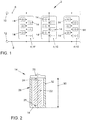
- the Fig. 1 shows, in a simplified and schematic representation, a section of a vehicle battery 2 of a motor vehicle, not shown in detail.
- the (vehicle) battery 2 is designed in particular as an electrochemical secondary battery, the motor vehicle being in particular an electrically driven or drivable motor vehicle, for example an electric or hybrid vehicle.
- the battery 2 has a number of battery modules 4, which are designed, for example, as lithium-ion accumulators. Examples are in the Fig. 1 only three battery modules 4 connected in parallel are shown, each of which is connected to a plus path 6 on the one hand and to a minus path 8 on the other. The paths 6, 8 each lead to a corresponding connection 10, 12 of the battery 2.
- the battery modules 4 are merely exemplary, each with six individual battery cells 14 ( Fig. 2 ) shown.
- the battery cells 14 are arranged adjacent to one another in the battery module 4 and are connected together to form the battery module 4.
- the battery cells 14 are in the Fig. 1 provided with reference symbols only as an example.
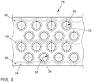
- the battery modules 4 each have a cell carrier (module carrier block) 16 as a cell connector ( Fig. 3 ).
- individually illustrated battery cells 14 are designed as round cells or cylindrical cells.
- the or each battery cell 14 has a cylindrical cell housing 18 which is closed by means of a cell cover 20 on the end face.
- An electrode coil 22 is arranged within the cell housing 18.
- the electrode coil 22 has two cell poles 24, 26, that is to say a positive pole 24 and a negative pole 26.
- the positive pole 24 is in contact with the cell cover 20.
- the negative pole 26 is contacted on the opposite end of the cell housing 18 to a housing base. In other words, it is the negative pole 26 switched to the cell housing 18.
- This means that the positive pole of the battery cell 14 is essentially formed by the cell cover 20, and the negative pole of the battery cell 14 is essentially formed by the cell housing 18.
- the cell cover 20 and the cell housing 18 are expediently electrically isolated from one another. Alternatively, it is conceivable, for example, that the positive pole 24 is connected to the cell housing 18 and the negative pole 26 is connected to the cell cover 20.
- the cell housing 18 has an outer jacket surface 28 with an axial cell height 30.
- An external thread 32 which extends essentially over the entire axial cell height 30 of the cell housing 18, is introduced into the jacket surface 28.
- the in Fig. 3 Cell carrier 16 shown only partially, has a carrier body 34 in which a number of threaded bores 36 are made.
- the threaded bores 36 each have an internal thread 38, which is designed to be complementary to the external thread 32.
- the threaded holes are in the Fig. 3 provided with reference symbols only as an example.
- the carrier body 34 is produced, for example, from a phase change matrix material, the phase change matrix material retaining a solid structure during a phase transition.
- the carrier body 34 is made at least partially from an electrically conductive material. In this case, for example, a punched grid is integrated into the carrier body 34, which is guided to the threaded bores 36 or to their internal threads 38.
- the battery cells 14 are screwed or screwed into the internal thread 38 of the threaded bores 36 of the cell carrier 16 by means of their external thread 32. Due to the contact between the cell pole 26 and the cell housing 18 and due to the electrically conductive material of the carrier body 34, the screwing in of the battery cells 14 is on the one hand non-positively attached to the cell carrier 16 and on the other hand electrically interconnected. In particular, the battery cells 14 are electrically conductively coupled to one another in an electrical parallel circuit.
- Coolant channels 40 which are integrated in the carrier body 34, are guided around the threaded bores 36.
- the coolant channels 40 are in the Fig. 3 shown in dash-dotted lines.
- the coolant channels 40 are guided in a wave-like or meandering manner around the threaded bores 36, so that each threaded bore 36 is at least partially surrounded or framed by a coolant channel 40.
- the coolant channels 40 can be designed, for example, as a continuous, that is, one-piece coolant channel, or as separate, parallel coolant channels.
- the coolant channels 40 are connected to a coolant circuit of the battery 2 and / or the motor vehicle, and a coolant or heating medium flows through them.
- the compact grid dimensions of the threaded bores 36 and the phase change matrix material of the carrier body 34 as well as the coolant channels 40 result in a particularly effective, reliable and operationally safe temperature management of the battery cells 14, which ensures high-performance, cell-related temperature control of the battery cells 14 during operation of the battery module 4 guaranteed.
Abstract
Die Erfindung betrifft ein Batteriemodul (4), aufweisend mindestens eine Batteriezelle (14) und einen Zellenträger (16), wobei die Batteriezelle (14) ein zylindrisches Zellgehäuse (18) mit einer außenseitigen Mantelfläche (28) aufweist, wobei in die Mantelfläche (28) ein Außengewinde (32) eingebracht ist, und wobei der Zellenträger (16) mindestens eine Gewindebohrung (36) mit einem Innengewinde (38) aufweist, in welche die mindestens eine Batteriezelle (14) eingedreht oder eindrehbar ist.The invention relates to a battery module (4), having at least one battery cell (14) and a cell carrier (16), the battery cell (14) having a cylindrical cell housing (18) with an outer jacket surface (28), wherein the jacket surface (28 ) an external thread (32) is introduced, and wherein the cell carrier (16) has at least one threaded bore (36) with an internal thread (38) into which the at least one battery cell (14) can be screwed or screwed.
Description
Die Erfindung betrifft ein Batteriemodul beispielsweise für ein Kraftfahrzeug, insbesondere für ein elektrisch angetriebenes oder antreibbares Kraftfahrzeug, wie beispielsweise ein Elektro- oder Hybridfahrzeug. Die Erfindung betrifft weiterhin eine Batteriezelle für ein solches Batteriemodul sowie ein elektrisch angetriebenes oder antreibbares Kraftfahrzeug mit einem derartigen Batteriemodul.The invention relates to a battery module, for example for a motor vehicle, in particular for an electrically powered or drivable motor vehicle, such as an electric or hybrid vehicle. The invention further relates to a battery cell for such a battery module as well as an electrically driven or drivable motor vehicle with such a battery module.
Elektrisch beziehungsweise elektromotorisch angetriebene oder antreibbare Kraftfahrzeuge, wie beispielsweise Elektro- oder Hybridfahrzeuge, umfassen in der Regel einen Elektromotor, mit dem eine oder beide Fahrzeugachsen antreibbar sind. Zur Versorgung mit elektrischer Energie ist der Elektromotor üblicherweise an eine fahrzeuginterne (Hochvolt-)Batterie als elektrischen Energiespeicher angeschlossen.Motor vehicles driven or drivable by electric or electric motors, such as for example electric or hybrid vehicles, generally comprise an electric motor with which one or both vehicle axles can be driven. To supply electrical energy, the electric motor is usually connected to a (high-voltage) battery inside the vehicle as an electrical energy store.
Unter einer insbesondere elektrochemischen Batterie ist hier und im Folgenden insbesondere eine sogenannte sekundäre Batterie (Sekundärbatterie) des Kraftfahrzeugs zu verstehen. Bei einer solchen (sekundären) Fahrzeugbatterie ist eine verbrauchte chemische Energie mittels eines elektrischen (Auf-)Ladevorgangs wiederherstellbar. Derartige Fahrzeugbatterien sind beispielsweise als elektrochemische Akkumulatoren, insbesondere als Lithium-Ionen-Akkumulatoren, ausgeführt. Zur Erzeugung oder Bereitstellung einer ausreichend hohen Betriebsspannung weisen solche Fahrzeugbatterien typischerweise mindestens ein Batteriemodul (Batteriezellmodul) auf, bei welchem mehrere einzelne Batteriezellen modular verschaltet sind.An electrochemical battery, in particular, is to be understood here and below as a so-called secondary battery (secondary battery) of the motor vehicle. In the case of such a (secondary) vehicle battery, the chemical energy used can be restored by means of an electrical (charging) process. Such vehicle batteries are designed, for example, as electrochemical accumulators, in particular as lithium-ion accumulators. In order to generate or provide a sufficiently high operating voltage, such vehicle batteries typically have at least one battery module (battery cell module) in which several individual battery cells are connected in a modular manner.
Die Batteriezellen können beispielsweise als sogenannte Rundzellen oder zylindrische Zellen ausgeführt sein. Derartige Rundzellen weisen in der Regel eine zylindrische oder runde Bauform mit einem (kreis-)zylindrischen Zellgehäuse auf.The battery cells can be designed as so-called round cells or cylindrical cells, for example. Round cells of this type generally have a cylindrical or round design with a (circular) cylindrical cell housing.
Beim Aufbau einer Fahrzeugbatterie aus Rundzellen ist es hierbei häufig notwendig, dass mehr als tausend einzelne Batteriezellen zu einem Batteriemodul gekoppelt werden müssen. Aufgrund der hohen Anzahl von Batteriezellen ist deren Handhabung im Zuge der Montage und deren Halterung im Modulverbund sowie die automotiv-taugliche Anbindung im Batteriemodul und die abschließende elektrische Kontaktierung mit einem großen Fertigungsaufwand verbunden. Dadurch werden sowohl die Fertigungsdauer als auch die Fertigungskosten derartiger Batteriemodule nachteilig erhöht.When building a vehicle battery from round cells, it is often necessary here that more than a thousand individual battery cells have to be coupled to form a battery module. Due to the high number of battery cells, their handling in the course of assembly and their holding in the module network as well as the automotive-compatible connection in the battery module and the subsequent electrical contacting are associated with a large production effort. This disadvantageously increases both the production time and the production costs of such battery modules.
Die Halterung oder Befestigung der Batterie- oder Rundzellen im Batteriemodul erfolgt typischerweise dadurch, dass eine vormontierte Zellanordnung der Batteriezellen durch eine Vergussmasse (beispielsweise Gießharz) stoffschlüssig gefügt oder geklebt wird. Anschließend werden die einzelnen Batteriezellen mittels eines Drahtbondens miteinander elektrisch leitend kontaktiert.The battery or round cells are typically held or fastened in the battery module in that a preassembled cell arrangement of the battery cells is cohesively joined or glued by means of a potting compound (for example cast resin). The individual battery cells are then electrically connected to one another by means of wire bonding.
Bei einem solchen Batteriemodul mit vergossenen oder stoffschlüssig gefügten Batteriezellen wird eine spätere Demontage zu Wartungs-, Reperatur- oder Recyclingfall nachteilig erschwert oder sogar unmöglich.In the case of such a battery module with encapsulated or cohesively joined battery cells, subsequent dismantling for maintenance, repair or recycling purposes is disadvantageously made difficult or even impossible.
Des Weiteren ist es häufig notwendig, dass die Vergussmasse bei der Fertigung des Batteriemoduls mit einer hohen Temperatur auf die Batteriezellen aufgebracht wird. Hierbei tritt das Problem auf, dass die Batteriezellen bei einer hohen Batteriezelltemperatur, beispielsweise höher als 45 °C, beginnen zu degenerieren. Dies bedeutet, dass bei derartig erhöhten Temperaturen elektrochemische Reaktionen innerhalb der Batteriezellen auftreten, welche die Batteriezellen beschädigen oder vollständig zerstören. Daher ist es notwendig, dass das Vergießen unter kontrollierten Bedingungen erfolgt, da einerseits die Temperatur der Vergussmasse einerseits hinreichend hoch sein muss, um ein gutes Fließ- und Benetzungsverhalten zu gewährleisten, aber andererseits eine Degeneration der Batteriezellen vermieden werden soll. Dadurch wird der Fertigungsaufwand des Batteriemoduls nachteilig weiter erhöht.Furthermore, it is often necessary for the casting compound to be applied to the battery cells at a high temperature during manufacture of the battery module. The problem arises here that the battery cells begin to degenerate at a high battery cell temperature, for example higher than 45 ° C. This means that at such elevated temperatures, electrochemical reactions occur within the battery cells, which damage or completely destroy the battery cells. It is therefore necessary that the potting takes place under controlled conditions, since on the one hand the temperature of the potting compound must be sufficiently high to ensure good flow and wetting behavior, but on the other hand it prevents degeneration of the battery cells shall be. This disadvantageously increases the manufacturing cost of the battery module.
Die Batteriezellen weisen jeweils zwei Zellpole, einen Minuspol und einen Pluspol, als elektrische Kontakt- oder Anbindungsstellen auf, so dass im Zuge der elektrischen Kontaktierung der Batteriezellen jeweils zwei Drahtbond-Schritte je Batteriezelle notwendig sind. Dadurch ist ein hoher Verschaltungsaufwand der Batteriezellen des Batteriemoduls realisiert, wodurch die Fertigungsdauer nachteilig erhöht wird.The battery cells each have two cell poles, a negative pole and a positive pole, as electrical contact or connection points, so that two wire bonding steps are necessary for each battery cell in the course of making electrical contact with the battery cells. As a result, the battery cells of the battery module are connected to a high degree of complexity, which disadvantageously increases the production time.
Aus der
In der
Der Erfindung liegt die Aufgabe zugrunde, ein besonders geeignetes Batteriemodul anzugeben. Insbesondere soll ein Batteriemodul angegeben werden, welches einen besonders niedrigen Montage- und Verschaltungsaufwand aufweist. Der Erfindung liegt weiterhin die Aufgabe zugrunde, eine Batteriezelle für ein solches Batteriemodul sowie ein elektrisch angetriebenes oder antreibbares Kraftfahrzeug mit einem derartigen Batteriemodul anzugeben.The invention is based on the object of specifying a particularly suitable battery module. In particular, a battery module is to be specified which has particularly low assembly and wiring costs. The invention is also based on the object of specifying a battery cell for such a battery module and an electrically driven or drivable motor vehicle with such a battery module.
Hinsichtlich des Batteriemoduls wird die Aufgabe mit den Merkmalen des Anspruchs 1 und hinsichtlich der Batteriezelle mit den Merkmalen des Anspruchs 9 sowie hinsichtlich des Kraftfahrzeugs mit den Merkmalen des Anspruchs 10 erfindungsgemäß gelöst. Vorteilhafte Ausgestaltungen und Weiterbildungen sind Gegenstand der Unteransprüche. Die im Hinblick auf das Batteriemodul angeführten Vorteile und Ausgestaltungen sind sinngemäß auch auf die Batteriezelle und/oder das Kraftfahrzeug übertragbar und umgekehrt.With regard to the battery module, the object is achieved according to the invention with the features of claim 1 and with regard to the battery cell with the features of claim 9 and with regard to the motor vehicle with the features of
Das erfindungsgemäße Batteriemodul ist beispielsweise für einen stationären Energiespeicher geeignet und eingerichtet. Vorzugsweise ist das Batteriemodul für einen fahrzeuginternen Energiespeicher, also für eine Fahrzeugbatterie eines elektrisch angetriebenen oder antreibbaren Kraftfahrzeugs, geeignet und eingerichtet. Das Batteriemodul weist mindestens eine Batteriezelle und einen Zellenträger (Modulträger, Trägerblock) als Zellverbinder auf.The battery module according to the invention is suitable and set up for a stationary energy store, for example. The battery module is preferably suitable and set up for a vehicle-internal energy store, that is to say for a vehicle battery of an electrically driven or drivable motor vehicle. The battery module has at least one battery cell and a cell carrier (module carrier, carrier block) as a cell connector.
Die Batteriezelle weist ein zylindrisches Zellgehäuse mit einer außenseitigen Mantelfläche auf. Mit anderen Worten ist die Batteriezelle als eine Rundzelle oder zylindrische Zelle ausgeführt. In die Mantelfläche des Zellgehäuses ist zumindest abschnittsweise ein Außengewinde oder Schraubengewinde, also eine profilierte Einkerbung, welche fortlaufend wendelartig, also als Schraubenlinie verläuft, eingebracht.The battery cell has a cylindrical cell housing with an outer jacket surface. In other words, the battery cell is designed as a round cell or a cylindrical cell. An external thread or screw thread, that is to say a profiled notch, which runs continuously in a helical manner, that is to say as a helical line, is introduced into the jacket surface of the cell housing at least in sections.
Der Zellenträger weist hierbei mindestens eine Gewindebohrung mit einem Innengewinde auf, in welche die mindestens eine Batteriezelle eingedreht (eingeschraubt, eingesetzt) oder eindrehbar (einschraubbar, einsetzbar) ist. Dies bedeutet, dass das Innengewinde der Gewindebohrung komplementär oder kämmend zum Außengewinde des Zellgehäuses ausgeführt ist, also dass die Gewindebohrung und die Batteriezelle ein zusammenpassendes Paar sind. Dadurch ist ein besonders geeignetes Batteriemodul gebildet.The cell carrier in this case has at least one threaded hole with an internal thread into which the at least one battery cell is screwed (screwed, inserted) or screwed (screwed, inserted). This means that the internal thread of the threaded hole is designed to be complementary or meshing with the external thread of the cell housing, that is to say that the threaded hole and the battery cell are a matching pair. A particularly suitable battery module is thereby formed.
Das Außengewinde der Batteriezelle wird somit zur Montage des Batteriemoduls in die Gewindebohrung des Zellenträgers eingedreht. Dadurch ist eine besonders einfache und aufwandreduzierte Montage des Batteriemoduls realisiert. Insbesondere ist somit auch eine vereinfachte Demontage einzelner Batteriezellen im Zuge einer Wartung, einer Reparatur, oder eines Recyclings ermöglicht.The external thread of the battery cell is thus screwed into the threaded hole of the cell carrier for assembly of the battery module. This enables the battery module to be mounted in a particularly simple and cost-effective manner. Especially This also enables simplified dismantling of individual battery cells in the course of maintenance, repair or recycling.
Durch das Außengewinde der Batteriezelle einerseits und das Innengewinde der Gewindebohrung des Zellenträgers andererseits ist eine kraftschlüssige Halterung oder Befestigung der Batteriezelle am Zellenträger realisiert. Unter einem "Kraftschluss" oder einer "kraftschlüssigen Verbindung" zwischen wenigstens zwei miteinander verbundenen Teilen wird hier und im Folgenden insbesondere verstanden, dass die miteinander verbundenen Teile aufgrund einer zwischen ihnen wirkenden Reibkraft gegen ein Abgleiten aneinander gehindert sind. Fehlt eine diese Reibkraft hervorrufende "Verbindungskraft" (dies bedeutet diejenige Kraft, welche die Teile gegeneinander drückt, beispielsweise eine Schraubenkraft oder die Gewichtskraft selbst), kann die kraftschlüssige Verbindung nicht aufrecht erhalten und somit gelöst werden.By means of the external thread of the battery cell on the one hand and the internal thread of the threaded hole of the cell carrier on the other hand, a non-positive holding or fastening of the battery cell on the cell carrier is realized. A "force fit" or a "force fit connection" between at least two interconnected parts is understood here and hereinafter in particular to mean that the interconnected parts are prevented from sliding off one another due to a frictional force acting between them. If a "connecting force" causing this frictional force is missing (this means the force which presses the parts against one another, for example a screw force or the weight force itself), the force-fit connection cannot be maintained and thus released.
Die Außen- und Innengewinde des Zellgehäuses beziehungsweise des Zellenträgers sind hierbei beispielsweise spanend über mechanische (Nach-)Bearbeitung, oder spanlos (umformend) mittels Gießen oder additiven Fertigungsverfahren hergestellt.The external and internal threads of the cell housing or of the cell carrier are produced, for example, by machining via mechanical (post) processing, or non-cutting (forming) by means of casting or additive manufacturing processes.
Im Gegensatz zum Stand der Technik erfolgt die kraftschlüssige Gewinde- oder Schraubverbindung nicht lediglich im Bereich einer Stirnseite des Zellgehäuses, sondern entlang dessen Mantelfläche. Dadurch ist im Vergleich zum Stand der Technik ein Wesentlich größerer Eingriff der Gewinde, also ein verlängerter Verbindungs- oder Fügebereich, zwischen der Batteriezelle und dem Zellenträger ermöglicht. Somit ist eine betriebssichere, vibrations- und schockbeständige Verbindung zwischen der mindestens einen Batteriezelle und dem Zellenträger realisiert.In contrast to the prior art, the force-fit thread or screw connection is not only made in the area of an end face of the cell housing, but along its outer surface. As a result, in comparison to the prior art, a significantly greater engagement of the thread, that is to say an extended connecting or joining area, is made possible between the battery cell and the cell carrier. An operationally reliable, vibration and shock-resistant connection between the at least one battery cell and the cell carrier is thus implemented.
In einer vorteilhaften Ausführung erstreckt sich das Außengewinde im Wesentlichen über die komplette axiale Zellhöhe des Zellgehäuses. Mit anderen Worten ist das Zellgehäuse nach Art eines Gewindebolzens ausgeführt. Dadurch ist ein besonders langer und großflächiger Verbindungs- oder Fügebereich realisiert, wodurch eine besonders betriebssichere, vibrations- und schockbeständige Verbindung zwischen der mindestens einen Batteriezelle und dem Zellenträger gewährleistet ist.In an advantageous embodiment, the external thread extends essentially over the entire axial cell height of the cell housing. In other words, the cell housing is designed in the manner of a threaded bolt. As a result, a particularly long and large-area connection or joining area is implemented, which creates a particularly reliable, vibration and shock-resistant connection is guaranteed between the at least one battery cell and the cell carrier.
Vorzugsweise weist die Gewindebohrung eine hinreichende axiale Tiefe auf, so dass die Batteriezelle möglichst vollständig in die Gewindebohrung eingedreht oder eindrehbar ist.The threaded hole preferably has a sufficient axial depth so that the battery cell can be screwed or screwed into the threaded hole as completely as possible.
In einer geeigneten Weiterbildung ist ein Zellpol, also der Pluspol oder der Minuspol der Batteriezelle auf das Zellgehäuse geschaltet. Dies bedeutet, dass das Zellgehäuse, insbesondere das Außengewinde, effektiv einen der Zellpole der Batteriezelle bildet. Dadurch ist eine besonders einfache Kontaktierung der Batteriezelle ermöglicht.In a suitable development, a cell pole, that is to say the positive pole or the negative pole of the battery cell, is connected to the cell housing. This means that the cell housing, in particular the external thread, effectively forms one of the cell poles of the battery cell. This enables particularly simple contacting of the battery cell.
Der jeweils andere Zellpol wird beispielsweise mittels Drahtbonden oder mittels (Laser-)Schweißens kontaktiert. Ebenso denkbar ist beispielsweise eine bodenseitige Kontaktstelle der Gewindebohrung, beispielsweise nach Art eines Federkontaktes, wodurch eine weitere Vereinfachung der Montage des Batteriemoduls bewirkt wird.The respective other cell pole is contacted by means of wire bonding or (laser) welding, for example. Likewise conceivable, for example, is a bottom-side contact point of the threaded hole, for example in the manner of a spring contact, which further simplifies the assembly of the battery module.
In einer möglichen Ausgestaltung ist der Zellenträger zumindest teilweise aus einem elektrisch leitfähigen Material gefertigt. Das elektrisch leitfähige Material ist beispielsweise ein Metall, insbesondere ein Kupfer- oder Aluminiummaterial. Hierbei ist es beispielsweise möglich, dass der Zellenträger ein Stanzgitter oder eine Stromschiene aus dem elektrisch leitfähigen Material aufweist, welche(s) in ein elektrisch nicht leitfähiges Trägermaterial, beispielsweise als Einlegeteil, integriert ist. Dadurch ist eine besonders einfache und aufwandsreduzierte Kontaktierung und/oder Verschaltung der Batteriezellen möglich. Die Konjunktion "und/oder" ist hier und im Folgenden derart zu verstehen, dass die mittels dieser Konjunktion verknüpften Merkmale sowohl gemeinsam als auch als Alternativen zueinander ausgebildet sein können.In one possible embodiment, the cell carrier is made at least partially from an electrically conductive material. The electrically conductive material is, for example, a metal, in particular a copper or aluminum material. In this case it is possible, for example, for the cell carrier to have a stamped grid or a busbar made of the electrically conductive material, which is integrated into an electrically non-conductive carrier material, for example as an insert. This makes contacting and / or interconnection of the battery cells possible in a particularly simple and effortless manner. The conjunction “and / or” is to be understood here and in the following in such a way that the features linked by means of this conjunction can be designed both together and as alternatives to one another.
Alternativ ist es beispielsweise denkbar, dass der Zellenträger aus einem elektrisch nicht leitfähigen Material, beispielsweise aus einem Kunststoffmaterial, gefertigt ist. Der Zellenträger ist hierbei beispielsweise aus einem ABS- (AcrylnitrilButadien-Styrol-Copolymere) oder einem PP-Kunststoffmaterial (Polypropylen), bedarfsweise auch mit Glasfaserverstärkung (z.B. PP GF 30), hergestellt. Dadurch ist ein besonders baugewichts- und kostenreduziertes Batteriemodul realisiert.Alternatively, it is conceivable, for example, for the cell carrier to be manufactured from an electrically non-conductive material, for example from a plastic material is. The cell carrier is made from an ABS (acrylonitrile-butadiene-styrene copolymer) or a PP plastic material (polypropylene), if necessary also with glass fiber reinforcement (eg PP GF 30). As a result, a battery module that is particularly lightweight and cost-effective is realized.
In einer besonders zweckmäßigen Ausbildung ist die Batteriezelle im eingedrehten Zustand elektrisch leitend kontaktiert. Dies bedeutet, dass durch das Einschrauben oder Eindrehen der Batteriezellen in die Gewindebohrungen des Zellenträgers die elektrische Kontaktierung zumindest eines Zellpols der Batteriezellen erfolgt. Bei einer Anzahl von in den Zellenträger eingedrehten Batteriezellen erfolgt hierbei vorzugsweise elektrischen Parallelschaltung der kontaktierten Zellpole. Dadurch entfallen im Vergleich zum Stand der Technik beispielsweise die Hälfte der zur Kontaktierung und/oder Verschaltung notwendigen Drahtbond-Schritte, da ein Zellpol der Batteriezelle bereits durch das Eindrehen in die Gewindebohrung kontaktiert wird.In a particularly expedient embodiment, the battery cell is electrically conductively contacted in the screwed-in state. This means that by screwing or screwing the battery cells into the threaded bores of the cell carrier, electrical contact is made with at least one cell pole of the battery cells. In the case of a number of battery cells screwed into the cell carrier, the contacted cell poles are preferably connected in parallel. As a result, compared to the prior art, for example, half of the wire bonding steps required for contacting and / or interconnection are omitted, since contact is made with a cell pole of the battery cell by screwing it into the threaded hole.
Die insbesondere elektrochemischen Batteriezellen sind beispielsweise als Lithium-lonen-Batteriezellen ausgeführt. Derartige Batteriezellen weisen in der Regel einen Wirkungsgrad von etwa 95% auf, wobei die auftretenden Verluste in Wärmeenergie gewandelt werden. Für einen effizienten und zuverlässigen Einsatz des Batteriemoduls in einem Kraftfahrzeug ist es daher notwendig, dass die Batteriezellen im Betrieb auf eine Betriebstemperatur, beispielsweise 25 °C, temperiert werden, da einerseits Degenerationen bei Batterietemperaturen höher als 45 °C beginnen, und andererseits die Leistung der Lithium-Ionen-Batteriezellen unterhalb von -5 °C abnimmt.The especially electrochemical battery cells are designed as lithium-ion battery cells, for example. Such battery cells usually have an efficiency of around 95%, with the losses that occur being converted into thermal energy. For efficient and reliable use of the battery module in a motor vehicle, it is therefore necessary that the battery cells are tempered to an operating temperature, for example 25 ° C, during operation, since on the one hand degenerations begin at battery temperatures higher than 45 ° C, and on the other hand the performance of the Lithium-ion battery cells decreases below -5 ° C.
Zum Zwecke einer Temperierung oder eines Temperaturmanagements, und somit zum Zwecke eines möglichst leistungsoptimierten Betriebs des Batteriemoduls, ist in einer geeigneten Ausführung mindestens ein Kühlmittelkanal, also eine zur Führung von Kühl- oder Wärmefluiden vorgesehene Kanalstruktur, in den Zellenträger integriert, welcher um die mindestens eine Gewindebohrung geführt ist.For the purpose of temperature control or temperature management, and thus for the purpose of a performance-optimized operation of the battery module, at least one coolant channel, i.e. a channel structure provided for guiding cooling or heating fluids, is integrated into the cell carrier in a suitable embodiment, which around the at least one Threaded hole is guided.
Somit ist eine performante oder leistungsfähige, zellnahe Temperierung der Batteriezellen ermöglicht.This enables high-performance or high-performance, cell-level temperature control of the battery cells.
Im Montage- oder Einbauzustand ist der mindestens eine Kühlmittelkanal geeigneterweise an einen entsprechenden (externen) Kühlmittelkreislauf angeschlossen, und von einem Kühl- oder Wärmemittel durchströmt. Dadurch werden eine effektive und betriebssichere Kühlung und/oder eine Wärmespeicherung für die Batteriezellen des Batteriemoduls realisiert, wodurch die Lebensdauer der Batteriezellen und somit des Batteriemoduls erhöht werden.In the assembled or installed state, the at least one coolant channel is suitably connected to a corresponding (external) coolant circuit and a coolant or heating medium flows through it. As a result, effective and operationally reliable cooling and / or heat storage for the battery cells of the battery module are implemented, as a result of which the service life of the battery cells and thus of the battery module are increased.
In einer zusätzlichen oder alternativen Ausgestaltung ist es für eine Temperierung oder ein Temperaturmanagement der Batteriezellen vorgesehen, dass im Bereich der oder jeder Gewindebohrung ein Phasenwechselmaterial (engl. phase change material, PCM) als Latentwärmespeicher (engl. latent heat system, LHS) in den Zellenträger eingebracht ist, welches bei einem Phasenübergang eine feste Struktur beibehält. Dies bedeutet, dass das Phasenwechselmaterial sowohl vor als auch nach dem Phasenübergang ein Festkörpermaterial ist, sich also beispielsweise im Zuge des Phasenübergangs nicht verflüssigt.In an additional or alternative embodiment, for temperature control or temperature management of the battery cells, a phase change material (PCM) as a latent heat storage (LHS) in the cell carrier is provided in the area of the or each threaded hole is introduced, which retains a solid structure during a phase transition. This means that the phase change material is a solid material both before and after the phase transition, that is to say, for example, does not liquefy in the course of the phase transition.
Der Zellenträger ist hierbei insbesondere aus einem PCM-Matrix-Material gefertigt. Dadurch wird die Wärmekapazität des Zellenträgers erhöht. Somit ist es beispielsweise möglich, dem umgebenden Zellenträgermaterial und/oder den Batteriezellen sowohl Wärme als auch Kälte zu entziehen und entsprechend einzuspeichern. Durch das eingesetzte oder eingebrachte PCM ist es beispielsweise möglich, Temperaturschwankungen der Batterietemperatur auszugleichen und/oder die Batterietemperatur zu stabilisieren. Dadurch werden Wärmespitzen der Batterietemperatur im Wesentlichen passiv verhindert, ohne dass die Batteriezelle oder der Zellenträger aktiv gekühlt werden muss.The cell carrier is in particular made of a PCM matrix material. This increases the heat capacity of the cell carrier. It is thus possible, for example, to withdraw both heat and cold from the surrounding cell carrier material and / or the battery cells and to store them accordingly. The PCM used or introduced makes it possible, for example, to compensate for temperature fluctuations in the battery temperature and / or to stabilize the battery temperature. As a result, thermal peaks in the battery temperature are essentially passively prevented without the battery cell or the cell carrier having to be actively cooled.
In einer denkbaren Weiterbildung ist eine Anzahl von Gewindebohrungen in einem zentriert-rechteckigen oder hexagonalen Rastermaß im Zellenträger angeordnet. Mit anderen Worten sind benachbarte Reihen von Gewindebohrungen gegeneinander versetzt angeordnet, so dass eine besonders bauraumkompakte Anordnung der Batteriezellen realisiert ist. Dadurch wird der Bauraumbedarf des Batteriemoduls vorteilhaft reduziert, was insbesondere hinsichtlich Einbau- oder Anwendungssituationen in einem Kraftfahrzeug vorteilhaft ist.In a conceivable development, a number of threaded bores are arranged in a centered, rectangular or hexagonal grid dimension in the cell carrier. In other words, adjacent rows of threaded bores are offset from one another, so that a particularly compact installation space Arrangement of the battery cells is realized. This advantageously reduces the installation space required by the battery module, which is particularly advantageous with regard to installation or application situations in a motor vehicle.
Die erfindungsgemäße Batteriezelle ist für ein vorstehend beschriebenes Batteriemodul geeignet und eingerichtet. Die Batteriezelle ist als eine Rundzelle oder zylindrische Zelle mit einem zylindrischen Zellgehäuse ausgeführt, wobei in eine außenseitige Mantelfläche des Zellgehäuses ein Außen- oder Schraubengewinde eingebracht ist.The battery cell according to the invention is suitable and set up for a battery module described above. The battery cell is designed as a round cell or cylindrical cell with a cylindrical cell housing, with an external or screw thread being introduced into an outer lateral surface of the cell housing.
Die Batteriezelle ist mittels des Außengewindes in eine Gewindebohrung eines Zellenträgers des Batteriemoduls eindrehbar, wobei die Batteriezelle hierbei kraftschlüssig am Zellenträger befestigt, und vorzugsweise elektrisch leitfähig kontaktiert oder verschaltet wird. Dadurch ist eine besonders einfache und aufwandreduzierte Montage und Verschaltung des Batteriemoduls realisierbar. Insbesondere ist auch eine vereinfachte Demontage einzelner Batteriezellen aus dem Batteriemodul im Zuge einer Wartung, einer Reparatur, oder eines Recyclings ermöglicht.The battery cell can be screwed into a threaded bore of a cell carrier of the battery module by means of the external thread, the battery cell being fastened to the cell carrier in a force-locking manner, and preferably contacted or connected in an electrically conductive manner. As a result, a particularly simple and cost-reduced assembly and connection of the battery module can be implemented. In particular, simplified dismantling of individual battery cells from the battery module in the course of maintenance, repair or recycling is also made possible.
In einer bevorzugten Anwendung ist das vorstehend beschriebene Batteriemodul ein Teil einer Fahrzeugbatterie eines elektrisch angetriebenen oder antreibbaren Kraftfahrzeugs, insbesondere eines Hybrid- oder Elektrofahrzeugs. Durch das erfindungsgemäße Batteriemodul wird der Fertigungsaufwand, und somit die Fertigungskosten des Kraftfahrzeugs vorteilhaft reduziert.In a preferred application, the battery module described above is part of a vehicle battery of an electrically powered or drivable motor vehicle, in particular a hybrid or electric vehicle. The production effort and thus the production costs of the motor vehicle are advantageously reduced by the battery module according to the invention.
Nachfolgend ist ein Ausführungsbeispiel der Erfindung anhand einer Zeichnung näher erläutert. Darin zeigen in schematischen und vereinfachten Darstellungen:
- Fig. 1
- ausschnittsweise eine Fahrzeugbatterie eines Kraftfahrzeugs, mit einer Anzahl von Batteriemodulen mit jeweils einer Anzahl von Batteriezellen,
- Fig. 2
- in Schnittansicht eine Batteriezelle, und
- Fig. 3
- in Draufsicht einen Zellenträger des Batteriemoduls mit Gewindebohrungen und integrierten Kühlmittelkanälen.
- Fig. 1
- a section of a vehicle battery of a motor vehicle, with a number of battery modules, each with a number of battery cells,
- Fig. 2
- a battery cell in sectional view, and
- Fig. 3
- in plan view a cell carrier of the battery module with threaded bores and integrated coolant channels.
Einander entsprechende Teile und Größen sind in allen Figuren stets mit den gleichen Bezugszeichen versehen.Corresponding parts and sizes are always provided with the same reference symbols in all figures.
Die
Die Batterie 2 weist eine Anzahl von Batteriemodulen 4 auf, welche beispielsweise als Lithium-Ionen-Akkumulatoren ausgeführt sind. Beispielhaft sind in der
In der
Die in
Das Zellgehäuse 18 weist eine außenseitige Mantelfläche 28 mit einer axialen Zellhöhe 30 auf. In die Mantelfläche 28 ist ein Außengewinde 32 eingebracht, welches sich im Wesentlichen über die komplette axiale Zellhöhe 30 des Zellgehäuses 18 erstreckt.The
Der in
Der Trägerkörper 34 ist beispielsweise aus einem Phasenwechsel-Matrix-Material hergestellt, wobei das Phasenwechsel-Matrix-Material bei einem Phasenübergang eine feste Struktur behält. Der Trägerkörper 34 ist hierbei zumindest teilweise aus einem elektrisch leitenden Material hergestellt. In den Trägerkörper 34 ist hierbei beispielsweise ein Stanzgitter integriert, welches an die Gewindebohrungen 36 beziehungsweise an deren Innengewinde 38 geführt ist.The
Zur Montage des Batteriemoduls 4 werden die Batteriezellen 14 mittels ihres Außengewindes 32 in die Innengewinde 38 der Gewindebohrungen 36 des Zellenträgers 16 eingedreht oder eingeschraubt. Aufgrund der Kontaktierung des Zellpols 26 mit dem Zellgehäuse 18 sowie aufgrund des elektrisch leitenden Materials des Trägerkörpers 34 werden die Batteriezellen 14 durch das Eindrehen einerseits kraftschlüssig am Zellenträger 16 befestigt und andererseits elektrisch miteinander verschaltet. Insbesondere werden die Batteriezellen 14 hierbei in einer elektrischen Parallelschaltung miteinander elektrisch leitfähig gekoppelt.To assemble the
In dem Ausschnitt der
Um die Gewindebohrungen 36 sind Kühlmittelkanäle 40 geführt, welche in den Trägerkörper 34 integriert sind. Die Kühlmittelkanäle 40 sind in der
Im Montage- oder Einbauzustand sind die Kühlmittelkanäle 40 an einen Kühlmittelkreislauf der Batterie 2 und/oder des Kraftfahrzeugs angeschlossen, und von einem Kühl- oder Wärmemittel durchströmt. Durch das bauraumkompakte Rastermaß der Gewindebohrungen 36 und durch das Phasenwechsel-Matrix-Material des Trägerkörpers 34 sowie durch die Kühlmittelkanäle 40 ist ein besonders effektives, zuverlässiges und betriebssicheres Temperaturmanagement der Batteriezellen 14 realisiert, welches eine performante, zellnahe Temperierung der Batteriezellen 14 im Betrieb des Batteriemoduls 4 gewährleistet.In the assembled or installed state, the
Die beanspruchte Erfindung ist nicht auf das vorstehend beschriebene Ausführungsbeispiel beschränkt. Vielmehr können auch andere Varianten der Erfindung von dem Fachmann hieraus im Rahmen der offenbarten Ansprüche abgeleitet werden, ohne den Gegenstand der beanspruchten Erfindung zu verlassen. Insbesondere sind ferner alle im Zusammenhang mit dem Ausführungsbeispiel beschriebenen Einzelmerkmale im Rahmen der offenbarten Ansprüche auch auf andere Weise kombinierbar, ohne den Gegenstand der beanspruchten Erfindung zu verlassen.The claimed invention is not limited to the embodiment described above. Rather, other variants of the invention can also be derived therefrom by the person skilled in the art within the scope of the disclosed claims without departing from the subject matter of the claimed invention. In particular, all individual features described in connection with the exemplary embodiment are also included within the scope of the disclosed claims can be combined in other ways without departing from the subject matter of the claimed invention.
- 22
- FahrzeugbatterieVehicle battery
- 44th
- BatteriemodulBattery module
- 66
- PluspfadPlus path
- 88th
- MinuspfadMinus path
- 1010
- Anschlussconnection
- 1212
- Anschlussconnection
- 1414th
- BatteriezelleBattery cell
- 1616
- ZellenträgerCell carrier
- 1818th
- ZellgehäuseCell housing
- 2020th
- ZelldeckelCell cover
- 2222nd
- ElektrodenwickelElectrode coil
- 2424
- Zellpol/PluspolCell pole / positive pole
- 2626th
- Zellpol/MinuspolCell pole / negative pole
- 2828
- MantelflächeOuter surface
- 3030th
- ZellhöheCell height
- 3232
- AußengewindeExternal thread
- 3434
- TrägerkörperCarrier body
- 3636
- GewindebohrungThreaded hole
- 3838
- Innengewindeinner thread
- 4040
- KühlmittelkanalCoolant duct
Claims (10)
dadurch gekennzeichnet,
dass sich das Außengewinde (32) im Wesentlichen über die komplette axiale Zellhöhe (30) des Zellgehäuses (18) erstreckt.Battery module (4) according to claim 1,
characterized,
that the external thread (32) extends essentially over the entire axial cell height (30) of the cell housing (18).
dadurch gekennzeichnet,
dass ein Zellpol (26) der Batteriezelle (14) auf das Zellgehäuse (18) geschaltet ist.Battery module (4) according to claim 1 or 2,
characterized,
that a cell pole (26) of the battery cell (14) is connected to the cell housing (18).
dadurch gekennzeichnet,
dass der Zellenträger (16) zumindest teilweise aus einem elektrisch leitfähigen Material gefertigt ist.Battery module (4) according to one of claims 1 to 3,
characterized,
that the cell carrier (16) is made at least partially from an electrically conductive material.
dadurch gekennzeichnet,
dass die Batteriezelle (14) in eingedrehten Zustand elektrisch leitend kontaktiert ist.Battery module (4) according to one of claims 1 to 4,
characterized,
that the battery cell (14) is electrically conductively contacted in the screwed-in state.
dadurch gekennzeichnet,
dass ein Kühlmittelkanal (40) in den Zellenträger (16) integriert ist, welcher um die mindestens eine Gewindebohrung (36) geführt ist.Battery module (4) according to one of claims 1 to 5,
characterized,
that a coolant channel (40) is integrated into the cell carrier (16), which is guided around the at least one threaded hole (36).
dadurch gekennzeichnet,
dass im Bereich der Gewindebohrung (36) ein Phasenwechselmaterial in den Zellenträger (16) eingebracht ist, welches bei einem Phasenübergang eine feste Struktur behält.Battery module (4) according to one of claims 1 to 6,
characterized,
that a phase change material is introduced into the cell carrier (16) in the area of the threaded bore (36), which material retains a solid structure during a phase transition.
dadurch gekennzeichnet,
dass eine Anzahl von Gewindebohrungen (36) in einem zentriert-rechteckigen oder hexagonalen Rastermaß im Zellenträger (16) angeordnet ist.Battery module (4) according to one of Claims 1 to 7,
characterized,
that a number of threaded bores (36) are arranged in a centered rectangular or hexagonal grid dimension in the cell carrier (16).
Applications Claiming Priority (1)
| Application Number | Priority Date | Filing Date | Title |
|---|---|---|---|
| DE102019207207.0A DE102019207207A1 (en) | 2019-05-17 | 2019-05-17 | Battery module for a motor vehicle |
Publications (2)
| Publication Number | Publication Date |
|---|---|
| EP3739660A1 true EP3739660A1 (en) | 2020-11-18 |
| EP3739660B1 EP3739660B1 (en) | 2023-07-12 |
Family
ID=70682642
Family Applications (1)
| Application Number | Title | Priority Date | Filing Date |
|---|---|---|---|
| EP20174185.7A Active EP3739660B1 (en) | 2019-05-17 | 2020-05-12 | Battery module for a motor vehicle |
Country Status (4)
| Country | Link |
|---|---|
| US (1) | US20200365932A1 (en) |
| EP (1) | EP3739660B1 (en) |
| CN (1) | CN111952496A (en) |
| DE (1) | DE102019207207A1 (en) |
Cited By (3)
| Publication number | Priority date | Publication date | Assignee | Title |
|---|---|---|---|---|
| DE102021110025A1 (en) | 2021-04-21 | 2022-10-27 | Dr. Ing. H.C. F. Porsche Aktiengesellschaft | Battery cell mounting assembly and electric vehicle |
| WO2023285212A1 (en) * | 2021-07-12 | 2023-01-19 | Robert Bosch Gmbh | Battery cell, battery cell adapter, system having a battery cell and a battery cell adapter, and battery module cell holder |
| DE102022002480A1 (en) | 2022-07-07 | 2024-01-18 | Mercedes-Benz Group AG | Battery cell for a battery module of an electrical energy storage device and battery module |
Families Citing this family (5)
| Publication number | Priority date | Publication date | Assignee | Title |
|---|---|---|---|---|
| US11527798B2 (en) * | 2020-08-26 | 2022-12-13 | Bae Systems Information And Electronic Systems Integration Inc. | Battery mounting mechanism |
| DE102020210927A1 (en) | 2020-08-31 | 2022-03-03 | Robert Bosch Gesellschaft mit beschränkter Haftung | Cooling system for at least one battery |
| FR3118315A1 (en) * | 2020-12-22 | 2022-06-24 | Airbus Defence And Space Sas | Device for protecting and cooling a battery. |
| DE102021110914A1 (en) | 2021-04-28 | 2022-11-03 | Audi Aktiengesellschaft | Method of disassembling a battery assembly and disassembly assembly |
| DE102022111769B4 (en) * | 2022-05-11 | 2024-01-18 | Rheinisch-Westfälische Technische Hochschule Aachen, Körperschaft des öffentlichen Rechts | Battery device |
Citations (4)
| Publication number | Priority date | Publication date | Assignee | Title |
|---|---|---|---|---|
| DE10122682A1 (en) | 2000-05-12 | 2001-11-29 | Honda Motor Co Ltd | Cell module structure has inner, outer cell connectors coaxially aligned at end of cell that contact inner, outer joining connectors coaxially aligned in connector joining part when connected |
| US20090004556A1 (en) * | 2000-02-29 | 2009-01-01 | Said Al-Hallaj | Battery system thermal management |
| US20110135975A1 (en) * | 2008-08-14 | 2011-06-09 | Johnson Controls - Saft Advanced Power Solutions Llc | Battery module with sealed vent chamber |
| DE102015210671A1 (en) | 2015-06-11 | 2016-12-15 | Robert Bosch Gmbh | Battery cell with a disposed within a second terminal first terminal |
Family Cites Families (11)
| Publication number | Priority date | Publication date | Assignee | Title |
|---|---|---|---|---|
| JP3312852B2 (en) * | 1996-09-26 | 2002-08-12 | 松下電器産業株式会社 | Battery power supply |
| US20060113965A1 (en) * | 2004-11-30 | 2006-06-01 | Yoon-Cheol Jeon | Secondary battery module |
| JP4182451B1 (en) * | 2007-07-23 | 2008-11-19 | トヨタ自動車株式会社 | Assembled battery |
| US20120107662A1 (en) * | 2010-10-29 | 2012-05-03 | Roemmler Mike | Thermal management matrix |
| US20120308875A1 (en) * | 2011-01-06 | 2012-12-06 | Shinya Geshi | Battery module |
| WO2012164832A1 (en) * | 2011-05-31 | 2012-12-06 | パナソニック株式会社 | Cell block |
| JP5919065B2 (en) * | 2012-03-30 | 2016-05-18 | 本田技研工業株式会社 | Cylindrical battery mounting structure for electric vehicles |
| CN106410080A (en) * | 2016-09-27 | 2017-02-15 | 深圳市沃特玛电池有限公司 | Battery module |
| CN206558654U (en) * | 2017-02-23 | 2017-10-13 | 深圳市沃特玛电池有限公司 | A kind of new power battery module radiator structure |
| CN207233784U (en) * | 2017-08-17 | 2018-04-13 | 深圳市沃特玛电池有限公司 | A kind of battery structure |
| WO2019241871A1 (en) * | 2018-06-22 | 2019-12-26 | Charger Industries Canada Limited Partnership | Vibration-damped battery, battery container, and battery pack for use downhole |
-
2019
- 2019-05-17 DE DE102019207207.0A patent/DE102019207207A1/en active Pending
-
2020
- 2020-05-12 EP EP20174185.7A patent/EP3739660B1/en active Active
- 2020-05-18 CN CN202010418223.5A patent/CN111952496A/en active Pending
- 2020-05-18 US US16/876,743 patent/US20200365932A1/en active Pending
Patent Citations (4)
| Publication number | Priority date | Publication date | Assignee | Title |
|---|---|---|---|---|
| US20090004556A1 (en) * | 2000-02-29 | 2009-01-01 | Said Al-Hallaj | Battery system thermal management |
| DE10122682A1 (en) | 2000-05-12 | 2001-11-29 | Honda Motor Co Ltd | Cell module structure has inner, outer cell connectors coaxially aligned at end of cell that contact inner, outer joining connectors coaxially aligned in connector joining part when connected |
| US20110135975A1 (en) * | 2008-08-14 | 2011-06-09 | Johnson Controls - Saft Advanced Power Solutions Llc | Battery module with sealed vent chamber |
| DE102015210671A1 (en) | 2015-06-11 | 2016-12-15 | Robert Bosch Gmbh | Battery cell with a disposed within a second terminal first terminal |
Cited By (3)
| Publication number | Priority date | Publication date | Assignee | Title |
|---|---|---|---|---|
| DE102021110025A1 (en) | 2021-04-21 | 2022-10-27 | Dr. Ing. H.C. F. Porsche Aktiengesellschaft | Battery cell mounting assembly and electric vehicle |
| WO2023285212A1 (en) * | 2021-07-12 | 2023-01-19 | Robert Bosch Gmbh | Battery cell, battery cell adapter, system having a battery cell and a battery cell adapter, and battery module cell holder |
| DE102022002480A1 (en) | 2022-07-07 | 2024-01-18 | Mercedes-Benz Group AG | Battery cell for a battery module of an electrical energy storage device and battery module |
Also Published As
| Publication number | Publication date |
|---|---|
| EP3739660B1 (en) | 2023-07-12 |
| DE102019207207A1 (en) | 2020-11-19 |
| CN111952496A (en) | 2020-11-17 |
| US20200365932A1 (en) | 2020-11-19 |
Similar Documents
| Publication | Publication Date | Title |
|---|---|---|
| EP3739660B1 (en) | Battery module for a motor vehicle | |
| EP3275028B1 (en) | Battery block, and method for producing a battery block | |
| DE102010013025A1 (en) | Vehicle battery e.g. lithium ion battery for hybrid car, has cooling plate arranged in housing for controlling temperature of battery, where plate is provided with molds, and cooling pipe held in molds in force and/or form fit manner | |
| EP2854212A1 (en) | Heating and cooling device for a battery | |
| DE102008034868A1 (en) | Battery with a arranged in a battery housing heat conducting plate for tempering the battery | |
| DE102008010837A1 (en) | Battery with a arranged in a battery housing heat conducting plate for tempering the battery | |
| DE102018103713A1 (en) | Mechanical and thermal system for a modular battery with power electronics components | |
| DE102009035470A1 (en) | Battery for use in vehicle e.g. hybrid drive vehicle, has isolation elements whose height is larger than height of pole contacts during non-assembled condition of cells, so that isolation elements are projected above pole contacts | |
| WO2010012338A1 (en) | Battery, in particular a vehicle battery | |
| DE102012215205A1 (en) | Cell connector for use in battery cell module of battery in e.g. electromotive drivable motor car, has access devices connecting connector with terminals of cells, where covering device with which one of access devices is partly covered | |
| DE102008059947A1 (en) | Battery, particularly high power battery and vehicle battery for mild hybrid drives of motor vehicle, has heat conducting plate for maintaining temperature of battery, where heat conducting plate is arranged in battery housing | |
| DE102014019696A1 (en) | cell block | |
| DE102012211180A1 (en) | Energy storage module of several prismatic storage cells | |
| WO2011054586A1 (en) | Method for connecting a battery terminal on a first battery cell having a battery terminal to a second battery cell, battery having connected battery cells and battery system | |
| WO2016037763A1 (en) | Temperature control apparatus for the temperature control of an electrical power supply unit | |
| WO2011009619A1 (en) | Electrochemical energy storage and method for cooling or heating an electrochemical energy storage | |
| EP2735039B1 (en) | Cell contacting arrangement for an energy store | |
| WO2015121118A1 (en) | Electric energy storage device and method for extracting the heat from an electric energy storage device | |
| DE102019200817A1 (en) | Cooling device for cooling battery cells, batteries and motor vehicles | |
| EP2909873B1 (en) | Energy storage cell and energy storage module | |
| WO2015121117A1 (en) | Electric energy storage cell and method for extracting the heat from an electric energy storage cell | |
| EP3117472B1 (en) | Connector arrangement for electrically contacting arresters of an electrochemical cell | |
| DE102014202240A1 (en) | Cooling device for cooling at least one battery, in particular a lithium-ion battery | |
| DE102011076578A1 (en) | Energy storage module for battery of motor car, has end plates comprising two pairs of opposite sides at distances, where one of distances is greater than other distance, and tie rods engage at end plates at one of pairs of opposed sides | |
| DE102022120938A1 (en) | DEVICE FOR ELECTRICALLY CONNECTING AT LEAST TWO ELECTRICAL COMPONENTS, IN PARTICULAR AN ELECTRICALLY DRIVEN VEHICLE, TO A COOLING DEVICE |
Legal Events
| Date | Code | Title | Description |
|---|---|---|---|
| PUAI | Public reference made under article 153(3) epc to a published international application that has entered the european phase |
Free format text: ORIGINAL CODE: 0009012 |
|
| STAA | Information on the status of an ep patent application or granted ep patent |
Free format text: STATUS: THE APPLICATION HAS BEEN PUBLISHED |
|
| AK | Designated contracting states |
Kind code of ref document: A1 Designated state(s): AL AT BE BG CH CY CZ DE DK EE ES FI FR GB GR HR HU IE IS IT LI LT LU LV MC MK MT NL NO PL PT RO RS SE SI SK SM TR |
|
| AX | Request for extension of the european patent |
Extension state: BA ME |
|
| STAA | Information on the status of an ep patent application or granted ep patent |
Free format text: STATUS: REQUEST FOR EXAMINATION WAS MADE |
|
| 17P | Request for examination filed |
Effective date: 20210518 |
|
| RAV | Requested validation state of the european patent: fee paid |
Extension state: KH Effective date: 20210518 Extension state: MA Effective date: 20210518 Extension state: MD Effective date: 20210518 Extension state: TN Effective date: 20210518 |
|
| RAX | Requested extension states of the european patent have changed |
Extension state: BA Payment date: 20210518 Extension state: ME Payment date: 20210518 |
|
| RBV | Designated contracting states (corrected) |
Designated state(s): AL AT BE BG CH CY CZ DE DK EE ES FI FR GB GR HR HU IE IS IT LI LT LU LV MC MK MT NL NO PL PT RO RS SE SI SK SM TR |
|
| REG | Reference to a national code |
Ref document number: 502020004105 Country of ref document: DE Ref country code: DE Ref legal event code: R079 Free format text: PREVIOUS MAIN CLASS: H01M0002100000 Ipc: H01M0010040000 |
|
| GRAP | Despatch of communication of intention to grant a patent |
Free format text: ORIGINAL CODE: EPIDOSNIGR1 |
|
| STAA | Information on the status of an ep patent application or granted ep patent |
Free format text: STATUS: GRANT OF PATENT IS INTENDED |
|
| RIC1 | Information provided on ipc code assigned before grant |
Ipc: B60L 50/64 20190101ALN20230123BHEP Ipc: B60K 1/04 20060101ALN20230123BHEP Ipc: H01M 50/249 20210101ALI20230123BHEP Ipc: H01M 50/50 20210101ALI20230123BHEP Ipc: H01M 50/24 20210101ALI20230123BHEP Ipc: H01M 10/6557 20140101ALI20230123BHEP Ipc: H01M 10/655 20140101ALI20230123BHEP Ipc: H01M 50/213 20210101ALI20230123BHEP Ipc: H01M 10/643 20140101ALI20230123BHEP Ipc: H01M 10/625 20140101ALI20230123BHEP Ipc: H01M 50/107 20210101ALI20230123BHEP Ipc: H01M 10/613 20140101ALI20230123BHEP Ipc: H01M 10/04 20060101AFI20230123BHEP |
|
| INTG | Intention to grant announced |
Effective date: 20230216 |
|
| GRAS | Grant fee paid |
Free format text: ORIGINAL CODE: EPIDOSNIGR3 |
|
| GRAA | (expected) grant |
Free format text: ORIGINAL CODE: 0009210 |
|
| STAA | Information on the status of an ep patent application or granted ep patent |
Free format text: STATUS: THE PATENT HAS BEEN GRANTED |
|
| AK | Designated contracting states |
Kind code of ref document: B1 Designated state(s): AL AT BE BG CH CY CZ DE DK EE ES FI FR GB GR HR HU IE IS IT LI LT LU LV MC MK MT NL NO PL PT RO RS SE SI SK SM TR |
|
| REG | Reference to a national code |
Ref country code: CH Ref legal event code: EP |
|
| REG | Reference to a national code |
Ref country code: IE Ref legal event code: FG4D Free format text: LANGUAGE OF EP DOCUMENT: GERMAN |
|
| REG | Reference to a national code |
Ref country code: DE Ref legal event code: R096 Ref document number: 502020004105 Country of ref document: DE |
|
| P01 | Opt-out of the competence of the unified patent court (upc) registered |
Effective date: 20230713 |
|
| REG | Reference to a national code |
Ref country code: LT Ref legal event code: MG9D |
|
| REG | Reference to a national code |
Ref country code: NL Ref legal event code: MP Effective date: 20230712 |
|
| PG25 | Lapsed in a contracting state [announced via postgrant information from national office to epo] |
Ref country code: NL Free format text: LAPSE BECAUSE OF FAILURE TO SUBMIT A TRANSLATION OF THE DESCRIPTION OR TO PAY THE FEE WITHIN THE PRESCRIBED TIME-LIMIT Effective date: 20230712 |
|
| PG25 | Lapsed in a contracting state [announced via postgrant information from national office to epo] |
Ref country code: GR Free format text: LAPSE BECAUSE OF FAILURE TO SUBMIT A TRANSLATION OF THE DESCRIPTION OR TO PAY THE FEE WITHIN THE PRESCRIBED TIME-LIMIT Effective date: 20231013 |
|
| PG25 | Lapsed in a contracting state [announced via postgrant information from national office to epo] |
Ref country code: ES Free format text: LAPSE BECAUSE OF FAILURE TO SUBMIT A TRANSLATION OF THE DESCRIPTION OR TO PAY THE FEE WITHIN THE PRESCRIBED TIME-LIMIT Effective date: 20230712 |
|
| PG25 | Lapsed in a contracting state [announced via postgrant information from national office to epo] |
Ref country code: IS Free format text: LAPSE BECAUSE OF FAILURE TO SUBMIT A TRANSLATION OF THE DESCRIPTION OR TO PAY THE FEE WITHIN THE PRESCRIBED TIME-LIMIT Effective date: 20231112 |
|
| PG25 | Lapsed in a contracting state [announced via postgrant information from national office to epo] |
Ref country code: SE Free format text: LAPSE BECAUSE OF FAILURE TO SUBMIT A TRANSLATION OF THE DESCRIPTION OR TO PAY THE FEE WITHIN THE PRESCRIBED TIME-LIMIT Effective date: 20230712 Ref country code: RS Free format text: LAPSE BECAUSE OF FAILURE TO SUBMIT A TRANSLATION OF THE DESCRIPTION OR TO PAY THE FEE WITHIN THE PRESCRIBED TIME-LIMIT Effective date: 20230712 Ref country code: PT Free format text: LAPSE BECAUSE OF FAILURE TO SUBMIT A TRANSLATION OF THE DESCRIPTION OR TO PAY THE FEE WITHIN THE PRESCRIBED TIME-LIMIT Effective date: 20231113 Ref country code: NO Free format text: LAPSE BECAUSE OF FAILURE TO SUBMIT A TRANSLATION OF THE DESCRIPTION OR TO PAY THE FEE WITHIN THE PRESCRIBED TIME-LIMIT Effective date: 20231012 Ref country code: LV Free format text: LAPSE BECAUSE OF FAILURE TO SUBMIT A TRANSLATION OF THE DESCRIPTION OR TO PAY THE FEE WITHIN THE PRESCRIBED TIME-LIMIT Effective date: 20230712 Ref country code: LT Free format text: LAPSE BECAUSE OF FAILURE TO SUBMIT A TRANSLATION OF THE DESCRIPTION OR TO PAY THE FEE WITHIN THE PRESCRIBED TIME-LIMIT Effective date: 20230712 Ref country code: IS Free format text: LAPSE BECAUSE OF FAILURE TO SUBMIT A TRANSLATION OF THE DESCRIPTION OR TO PAY THE FEE WITHIN THE PRESCRIBED TIME-LIMIT Effective date: 20231112 Ref country code: HR Free format text: LAPSE BECAUSE OF FAILURE TO SUBMIT A TRANSLATION OF THE DESCRIPTION OR TO PAY THE FEE WITHIN THE PRESCRIBED TIME-LIMIT Effective date: 20230712 Ref country code: GR Free format text: LAPSE BECAUSE OF FAILURE TO SUBMIT A TRANSLATION OF THE DESCRIPTION OR TO PAY THE FEE WITHIN THE PRESCRIBED TIME-LIMIT Effective date: 20231013 Ref country code: FI Free format text: LAPSE BECAUSE OF FAILURE TO SUBMIT A TRANSLATION OF THE DESCRIPTION OR TO PAY THE FEE WITHIN THE PRESCRIBED TIME-LIMIT Effective date: 20230712 Ref country code: ES Free format text: LAPSE BECAUSE OF FAILURE TO SUBMIT A TRANSLATION OF THE DESCRIPTION OR TO PAY THE FEE WITHIN THE PRESCRIBED TIME-LIMIT Effective date: 20230712 |
|
| PG25 | Lapsed in a contracting state [announced via postgrant information from national office to epo] |
Ref country code: PL Free format text: LAPSE BECAUSE OF FAILURE TO SUBMIT A TRANSLATION OF THE DESCRIPTION OR TO PAY THE FEE WITHIN THE PRESCRIBED TIME-LIMIT Effective date: 20230712 |