EP3739362B1 - Reflektanzmessung mit flugzeitkameras - Google Patents
Reflektanzmessung mit flugzeitkameras Download PDFInfo
- Publication number
- EP3739362B1 EP3739362B1 EP20174659.1A EP20174659A EP3739362B1 EP 3739362 B1 EP3739362 B1 EP 3739362B1 EP 20174659 A EP20174659 A EP 20174659A EP 3739362 B1 EP3739362 B1 EP 3739362B1
- Authority
- EP
- European Patent Office
- Prior art keywords
- reflectance
- pixels
- pixel
- distance
- calibration
- Prior art date
- Legal status (The legal status is an assumption and is not a legal conclusion. Google has not performed a legal analysis and makes no representation as to the accuracy of the status listed.)
- Active
Links
Images


Classifications
-
- G—PHYSICS
- G01—MEASURING; TESTING
- G01S—RADIO DIRECTION-FINDING; RADIO NAVIGATION; DETERMINING DISTANCE OR VELOCITY BY USE OF RADIO WAVES; LOCATING OR PRESENCE-DETECTING BY USE OF THE REFLECTION OR RERADIATION OF RADIO WAVES; ANALOGOUS ARRANGEMENTS USING OTHER WAVES
- G01S17/00—Systems using the reflection or reradiation of electromagnetic waves other than radio waves, e.g. lidar systems
- G01S17/88—Lidar systems specially adapted for specific applications
- G01S17/89—Lidar systems specially adapted for specific applications for mapping or imaging
- G01S17/894—Three-dimensional [3D] imaging with simultaneous measurement of time-of-flight at a two-dimensional [2D] array of receiver pixels, e.g. time-of-flight cameras or flash lidar
-
- G—PHYSICS
- G01—MEASURING; TESTING
- G01S—RADIO DIRECTION-FINDING; RADIO NAVIGATION; DETERMINING DISTANCE OR VELOCITY BY USE OF RADIO WAVES; LOCATING OR PRESENCE-DETECTING BY USE OF THE REFLECTION OR RERADIATION OF RADIO WAVES; ANALOGOUS ARRANGEMENTS USING OTHER WAVES
- G01S7/00—Details of systems according to groups G01S13/00, G01S15/00, G01S17/00
- G01S7/48—Details of systems according to groups G01S13/00, G01S15/00, G01S17/00 of systems according to group G01S17/00
- G01S7/483—Details of pulse systems
- G01S7/486—Receivers
- G01S7/4865—Time delay measurement, e.g. time-of-flight measurement, time of arrival measurement or determining the exact position of a peak
-
- G—PHYSICS
- G01—MEASURING; TESTING
- G01S—RADIO DIRECTION-FINDING; RADIO NAVIGATION; DETERMINING DISTANCE OR VELOCITY BY USE OF RADIO WAVES; LOCATING OR PRESENCE-DETECTING BY USE OF THE REFLECTION OR RERADIATION OF RADIO WAVES; ANALOGOUS ARRANGEMENTS USING OTHER WAVES
- G01S17/00—Systems using the reflection or reradiation of electromagnetic waves other than radio waves, e.g. lidar systems
- G01S17/02—Systems using the reflection of electromagnetic waves other than radio waves
- G01S17/06—Systems determining position data of a target
- G01S17/08—Systems determining position data of a target for measuring distance only
- G01S17/10—Systems determining position data of a target for measuring distance only using transmission of interrupted, pulse-modulated waves
-
- G—PHYSICS
- G01—MEASURING; TESTING
- G01S—RADIO DIRECTION-FINDING; RADIO NAVIGATION; DETERMINING DISTANCE OR VELOCITY BY USE OF RADIO WAVES; LOCATING OR PRESENCE-DETECTING BY USE OF THE REFLECTION OR RERADIATION OF RADIO WAVES; ANALOGOUS ARRANGEMENTS USING OTHER WAVES
- G01S17/00—Systems using the reflection or reradiation of electromagnetic waves other than radio waves, e.g. lidar systems
- G01S17/88—Lidar systems specially adapted for specific applications
- G01S17/89—Lidar systems specially adapted for specific applications for mapping or imaging
-
- G—PHYSICS
- G01—MEASURING; TESTING
- G01S—RADIO DIRECTION-FINDING; RADIO NAVIGATION; DETERMINING DISTANCE OR VELOCITY BY USE OF RADIO WAVES; LOCATING OR PRESENCE-DETECTING BY USE OF THE REFLECTION OR RERADIATION OF RADIO WAVES; ANALOGOUS ARRANGEMENTS USING OTHER WAVES
- G01S7/00—Details of systems according to groups G01S13/00, G01S15/00, G01S17/00
- G01S7/48—Details of systems according to groups G01S13/00, G01S15/00, G01S17/00 of systems according to group G01S17/00
- G01S7/4802—Details of systems according to groups G01S13/00, G01S15/00, G01S17/00 of systems according to group G01S17/00 using analysis of echo signal for target characterisation; Target signature; Target cross-section
-
- G—PHYSICS
- G01—MEASURING; TESTING
- G01S—RADIO DIRECTION-FINDING; RADIO NAVIGATION; DETERMINING DISTANCE OR VELOCITY BY USE OF RADIO WAVES; LOCATING OR PRESENCE-DETECTING BY USE OF THE REFLECTION OR RERADIATION OF RADIO WAVES; ANALOGOUS ARRANGEMENTS USING OTHER WAVES
- G01S7/00—Details of systems according to groups G01S13/00, G01S15/00, G01S17/00
- G01S7/48—Details of systems according to groups G01S13/00, G01S15/00, G01S17/00 of systems according to group G01S17/00
- G01S7/483—Details of pulse systems
- G01S7/486—Receivers
- G01S7/4861—Circuits for detection, sampling, integration or read-out
- G01S7/4863—Detector arrays, e.g. charge-transfer gates
-
- G—PHYSICS
- G01—MEASURING; TESTING
- G01S—RADIO DIRECTION-FINDING; RADIO NAVIGATION; DETERMINING DISTANCE OR VELOCITY BY USE OF RADIO WAVES; LOCATING OR PRESENCE-DETECTING BY USE OF THE REFLECTION OR RERADIATION OF RADIO WAVES; ANALOGOUS ARRANGEMENTS USING OTHER WAVES
- G01S7/00—Details of systems according to groups G01S13/00, G01S15/00, G01S17/00
- G01S7/48—Details of systems according to groups G01S13/00, G01S15/00, G01S17/00 of systems according to group G01S17/00
- G01S7/491—Details of non-pulse systems
- G01S7/4912—Receivers
- G01S7/4915—Time delay measurement, e.g. operational details for pixel components; Phase measurement
-
- G—PHYSICS
- G01—MEASURING; TESTING
- G01S—RADIO DIRECTION-FINDING; RADIO NAVIGATION; DETERMINING DISTANCE OR VELOCITY BY USE OF RADIO WAVES; LOCATING OR PRESENCE-DETECTING BY USE OF THE REFLECTION OR RERADIATION OF RADIO WAVES; ANALOGOUS ARRANGEMENTS USING OTHER WAVES
- G01S7/00—Details of systems according to groups G01S13/00, G01S15/00, G01S17/00
- G01S7/48—Details of systems according to groups G01S13/00, G01S15/00, G01S17/00 of systems according to group G01S17/00
- G01S7/497—Means for monitoring or calibrating
Definitions
- the present disclosure is generally related to time-of-flight (ToF) measurements and is more particularly related to techniques for obtaining reflectance measurements using a ToF sensor.
- ToF time-of-flight
- depth measurements i.e., measurements of the distance to various features of an object or objects in view of an image sensor may be performed as so-called time-of-flight (ToF) measurements, which are distance measurements determined using the speed of light and image/pixel sensors.
- the distance to an object of interest is typically calculated per pixel and, once calculated, can be used for depth detection, gesture identification, object detection, and the like.
- the distance per pixel is combined to create a depth map that provides a three-dimensional image.
- ToF measurement technology is increasingly being found in portable electronic devices, such as cellular phones and "smart" devices.
- Each exposure requires that light generated from a light source be amplitude modulated using a modulating signal at a respective phase with respect to a reference signal applied to the pixels that demodulate light reflected from an object or objects of interest, the phase being different for different exposures.
- a modulating signal at 0°, 90°,180° and 270°, respectively, with respect to the reference signal.
- Measurement information from the four exposures is collected and compared to determine a depth map. For high-precision measurements, with extended unambiguous ranges, even more exposures, e.g., as many as nine separate raw measurements, may be performed.
- Patent document US 2016/178512 A1 proposes an active illumination range camera that acquires a range and a picture image of a scene and provides a reflectance for a feature in the scene responsive to a distance for the feature provided by the range image, a registered irradiance for the feature provided by the picture image and registered irradiance for a region of a calibration surface corresponding to the feature provided by an image of the calibration surface acquired by the range camera.
- Some embodiments relate to a method, in a time-of-flight (ToF) measurement device, the method including obtaining a distance measurement, using one or more pixels in a ToF sensor; obtaining an intensity measurement corresponding to the distance measurement, using the one or more pixels; and obtaining an intensity measurement corresponding to the distance measurement, using the one or more pixels; and calculating a reflectance value for the one or more pixels, based on the distance measurement, the intensity measurement, and a reflectance calibration factor, the reflectance calibration factor compensating for at least one of a viewing angle for the one or more pixels using Lambert's cosine law, and a difference between a distance to a planar, diffuse, calibration surface measured by the one or more pixels and a distance calibration value using inverse square law.
- the reflectance calibration factor is specific to the one or more pixels in the ToF sensor.
- said calculating includes multiplying the intensity measurement by the reflectance calibration factor and by a factor proportional to the square of the distance measurement.
- the method further includes using the calculated reflectance value to normalize a pixel value or group of pixel values in a two-dimensional image.
- the method includes obtaining a plurality of distance measurements using the ToF sensor, wherein each distance measurement is obtained using a respective pixel or group of pixels in the ToF sensor; obtaining an intensity measurement corresponding to each of the distance measurements, using the respective pixels or groups of pixels; and calculating a reflectance value corresponding to each intensity measurement, based on the intensity measurement, the respective distance measurement, and a respective reflectance calibration factor.
- the respective calibration factors are each specific to a respective pixel or group of pixels.
- said calculating includes multiplying the intensity measurement for the respective pixel or group of pixels by the reflectance calibration factor for the respective pixel or group of pixels and by a factor proportional to the square of the distance measurement for the respective pixel or group of pixels.
- the method further includes using the calculated reflectance values to normalize pixel values or groups of pixel values in a two-dimensional image.
- the method further includes forming a reflectance image from the calculated reflectance values.
- the method further includes forming a three-dimensional point-cloud including the distance measurements and the corresponding reflectance values.
- the method includes obtaining the calibration distance by measuring a reference distance to a calibration surface, using a reference pixel in the ToF sensor, and obtaining the calibration distance from the measured reference distance.
- the method includes obtaining the reflectance calibration factors by calculating the reflectance calibration factor for each of the respective pixels or groups of pixels as a function of a viewing angle for the pixel or group of pixels or a distance to a calibration surface measured by the pixel or group of pixels, or both, and a reference reflectance.
- the function is a function of R ref / cos ⁇ i,j , where R ref is the reference reflectance and ⁇ i , j is the viewing angle of the respective pixel or group of pixels, with respect to the optical axis of the ToF sensor.
- the method includes obtaining the reflectance calibration factors by, for each pixel or group of pixels, measuring an intensity of reflection from a calibration surface, using the pixel or group of pixels; scaling the measured intensity, based on the viewing angle for the pixel or group of pixels, with respect to the optical axis of the ToF sensor; calculating the reflectance calibration factor for the pixel or group of pixels as a function of the scaled measured intensity and a reference reflectance.
- Some embodiments relate to a time-of-flight (ToF) measurement device, including a light source configured to emit a series of light pulses formed by amplitude-modulating light with a modulating signal; a ToF sensor including a plurality of pixels configured to generate a respective plurality of pixel signal values in response to received light, wherein each pixel is configured to obtain its respective pixel signal value by demodulating received light using a reference signal; a reference signal generator configured to generate the reference signal and to provide the reference signal to the plurality of pixels; and control circuitry configured to control the light source, ToF sensor, and a reflectance map generator to obtain a distance measurement, using one or more pixels in the ToF sensor; obtain an intensity measurement corresponding to the distance measurement, using the one or more pixels; and calculate a reflectance value for the one or more pixels, based on the distance measurement, the intensity measurement, and a reflectance calibration factor, the reflectance calibration factor compensating for at least one of a viewing angle for the one or more pixels using Lambert's cosine law
- the reflectance calibration factor is specific to the one or more pixels in the ToF sensor.
- said calculating includes multiplying the intensity measurement by the reflectance calibration factor and by a factor proportional to the square of the distance measurement.
- control circuitry is configured to control the light source, ToF sensor, and reflectance map generator to obtain a plurality of distance measurements using the ToF sensor, wherein each distance measurement is obtained using a respective pixel or group of pixels in the ToF sensor; obtain an intensity measurement corresponding to each of the distance measurements, using the respective pixels or groups of pixels; and calculate a reflectance value corresponding to each intensity measurement, based on the intensity measurement, the respective distance measurement, and a respective reflectance calibration factor.
- the respective calibration factors are each specific to a respective pixel or group of pixels.
- the reflectance value is calculated by multiplying the intensity measurement for the respective pixel or group of pixels by the reflectance calibration factor for the respective pixel or group of pixels and by a factor proportional to the square of the distance measurement for the respective pixel or group of pixels.
- control circuitry is configured to control the light source, sensor, and reflectance map generator to measure a reference distance to a calibration surface, using a reference pixel in the ToF sensor, and obtain the calibration distance from the measured reference distance.
- control circuitry is configured to control the light source, sensor, and reflectance map generator to obtain the reflectance calibration factors by calculating the reflectance calibration factor for each of the respective pixels or groups of pixels as a function of a viewing angle for the pixel or group of pixels or a distance to a calibration surface measured by the pixel or group of pixels, or both, and a reference reflectance.
- the function is a function of R ref / cos ⁇ i,j , where R ref is the reference reflectance and ⁇ i,j is the viewing angle of the respective pixel or group of pixels, with respect to the optical axis of the ToF sensor.
- control circuitry is configured to control the light source, sensor, and reflectance map generator to obtain the reflectance calibration factors by, for each pixel or group of pixels, measuring an intensity of reflection from a calibration surface, using the pixel or group of pixels; scaling the measured intensity, based on the viewing angle for the pixel or group of pixels, with respect to the optical axis of the ToF sensor; calculating the reflectance calibration factor for the pixel or group of pixels as a function of the scaled measured intensity and a reference reflectance.
- Described herein are techniques for measuring the reflectance of an imaged object or objects, for each pixel of a time-of-flight (ToF) sensor.
- the reflectance is the effectiveness of an object's or material's surface in reflecting radiant energy, and can be understood as the percentage of light illuminating the object's or material's surface reflected back to the ToF sensor.
- a ToF sensor can be used to produce a reflectance map, along with a depth map. This can be used, for example, to classify imaged materials, and/or to provide additional data for object and face recognition.
- the reflectance data might also be used, for example, to detect skin color, or to detect sweat on human skin.
- Embodiments described in detail below include an example method for reflectance measurement, as implemented in a time-of-flight (ToF) measurement device.
- This example method includes the step of obtaining a distance measurement, using one or more pixels in a ToF sensor, and obtaining an intensity measurement corresponding to the distance measurement, using the same one or more pixels.
- the method further comprises calculating a reflectance value for the one or more pixels, based on the distance measurement, the intensity measurement, and a reflectance calibration factor. These steps may be carried out for each of several (or many) pixels or pixel groups, using reflectance calibration factors that are specific to the respective pixels or pixel groups.
- calculating the reflectance value comprises multiplying the intensity measurement by the reflectance calibration factor and by a factor proportional to the square of the distance measurement.
- the ToF measurement device obtains the calibration distance by measuring a reference distance to a calibration surface, e.g., using a reference pixel in the ToF sensor having a viewing angle aligned with the optical axis of the ToF sensor, and obtaining the calibration distance from the measured reference distance.
- the ToF measurement device calculates the reflectance calibration factor for each of the respective pixels or groups of pixels as a function of a viewing angle for the pixel or group of pixels or a distance to a calibration surface measured by the pixel or group of pixels, or both, and a reference reflectance.
- the reflectance calibration factors are obtained by, for each pixel or group of pixels: measuring an intensity of reflection from the calibration surface for the pixel or group of pixels; scaling the measured intensity, based on the viewing angle for the pixel or group of pixels, with respect to the optical axis of the ToF sensor; and calculating the reflectance calibration factor for the pixel or group of pixels as a function of the scaled measured intensity and a reference reflectance.
- Reflectance values calculated according to the techniques disclosed herein may be used to normalize pixel values or groups of pixel values in a two-dimensional image, for example. This could be used for machine-learning purposes, for example, allowing intensity values to be mapped to a fixed scale that is independent of the distance. As another example, reflectance values calculated according to these techniques may be used to form a reflectance image, or to form a three-dimensional point-cloud comprising the distance measurements and the corresponding reflectance values.
- image and image sensor are not limited to images or sensors involving visible light but encompass the use of visible light and other electromagnetic radiation.
- light as used herein is meant broadly and refers to visible light as well as infrared and ultraviolet radiation.
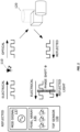
- FIG. 1 illustrates the basic principles of continuous-wave (CW) time-of-flight (TOF) measurements, which are well known.
- a light source 110 such as a light-emitting diode (LED) or vertical-cavity surface-emitting laser (VCSEL) is modulated with an electrical signal (e.g., a radio-frequency sinusoid at, for example, 300 MHz), so that the light source 110 emits an amplitude-modulated optical signal towards the target scene 120.
- an electrical signal e.g., a radio-frequency sinusoid at, for example, 300 MHz
- the light signal reflects from an object or objects in the scene 120 and arrives back at a pixel array 135 in the TOF sensor 130, with the time of flight to the target scene 120 and back imposing a phase shift of ⁇ on the optical signal as received at the pixel array 135, relative to the originally transmitted optical signal.
- the modulation signal 137 used to modulate the emitted light, or a phase-shifted version of it, is also supplied as a reference signal to the pixels in pixel array 135, to be correlated with the modulation signal superimposed on the reflected optical signal - in effect, the reflected optical signal is demodulated by each pixel in the pixel array 135.
- each of the pixels in pixel array 135 may in some instances be a photon mixing device, or PMD.
- Figure 2 illustrates the basic structure of an example PMD, which includes readout diodes A and B and modulation gates A and B.
- a reference signal is applied differentially across the modulation gates A and B, creating a gradient in electric potential across the p-substrate, while incoming light is received at a photo gate/diode.
- a differential sensor signal is generated across the readout diodes A and B. The sensor signal from a pixel may be integrated for a period of time to determine phase measurement information.
- the difference between voltages at the Read-A and Read-B nodes of the PMD corresponds to the correlation between the modulated optical signal detected by the photosensitive diode structures in the illustrated device and the reference signal, which is applied between the Mod-A and Mod-B nodes of the device.
- the PMD demodulate the modulated optical signal reflected from the target scene 120, producing a pixel signal value (in this case the difference between voltages at Read-A and Read-B) indicative of the distance traveled by the reflected optical signal, as discussed in further detail below.
- the phase difference between the emitted optical signal and the received reflection of that signal can be extracted by an N-phase shifting technique.
- This requires sampling the correlation function at N different points, e.g., by performing correlations using N different phase shifts of the reference signal, with respect to the modulating signal g(t). At least two measurements are required to calculate this phase shift, and hence to determine the distance traveled. This is often done using four different phase shifts, at 0, 90, 180, and 270 degrees, as this allows for a simple cancellation of systematic offsets in the correlation results.
- FIG. 3 shows how the correlations A0 and A1, at 0 and 90 degrees, respectively, correspond to a first phase vector having an "ideal" component corresponding to the actual difference traveled by the optical signal and a systematic component reflecting systematic error in the measurements and readout.
- the correlations A2 and A3, at 180 and 270 degrees, respectively correspond to a second phase vector pointing in the opposite direction, with an exactly opposite "ideal" component and an identical systematic component.
- the ideal components are represented by the vectors extending from the origin to the circle, while the systematic error components are represented by the smaller vectors.
- intensity measurements can in turn be used to measure the amount of light reflected from an object. Because of the modulated illumination signal used to perform the distance measurements, other light sources, such as sunlight or background lighting, do not influence these intensity measurements. Rather, the external influences on the intensity measurement value for a given pixel are the reflectance of the object or material imaged by the pixel and the distance from the ToF illumination unit to the imaged object or material and back to the pixel. Internal influences on the intensity measurement value include the intensity of the illumination, in the direction of the imaged object or material, the sensitivity of the pixel, and the measurement time.
- Described herein are techniques for compensating the influence of the distance to the object, so that a reflectance value for the imaged object or material can be obtained from the intensity measurement for a pixel. These techniques may also be used to compensate for variations in illumination intensity across a field of view, as well as for variations in pixel sensitivity.
- Reflectance from a surface depends on the surface angle ⁇ , which is the angle between the surface of the object, at a point viewed by a given pixel, and the ray extending from the object at that point to the pixel.
- ⁇ is the angle between the surface of the object, at a point viewed by a given pixel, and the ray extending from the object at that point to the pixel.
- the reflectance provides a unique way to sense a representation of an object. It provides additional information for object recognition applications, such as face identification and gesture detection. In many of these applications, the dependence on angle ⁇ does not matter, since the object classification model may be learned from many different angles anyway.
- a first step to be able to measure reflectance is camera calibration.
- each pixel in a ToF sensor may have variations in sensitivity.
- the illumination unit illuminating the object(s) or material of interest may not produce a uniform light distribution.
- obtaining a reference is required to have a scale for the sensed reflectance.
- One approach to calibration is to take a single intensity and depth image of a planar, diffuse, calibration surface, which is arranged so that the optical axis of the ToF sensor is normal to the calibration surface. This can be done, for example, when each ToF camera is calibrated during manufacturing. Alternatively, this might be performed for a ToF camera of a particular design, with the calibration results being used for similar cameras.
- One step of this calibration process is to transform the intensity measurement I i,j for each pixel i,j, as obtained from imaging the planar calibration surface, to a virtual sphere S, having its center at the optical center of the ToF sensor.
- intensity measurements, depth measurements, and the like may be performed on a pixel-by-pixel basis, or for a small group of neighboring pixels.
- the following discussion will refer to individual pixels arranged in a rectangular array, such that they can be conveniently indexed with indices i and j.
- a group of neighboring pixels may generally be substituted for each pixel in this discussion, and that these pixels or groups of pixels may be arranged in configurations other than a rectangular array.
- references to a "pixel i,j" may be understood to refer to an arbitrary pixel or group of pixels in a ToF sensor.
- a second step of the calibration procedure is to establish a correction factor, or reflectance calibration factor c i,j r, for each pixel.
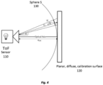
- FIG. 4 illustrates a ToF sensor 110 arranged with its optical axis pointing directly at planar, diffuse, calibration surface 120.
- the illumination source which emits modulated light towards calibration surface 120, is at the optical focal point of the ToF sensor 110; the same assumption is made for the pixels of the ToF sensor 110.
- the distance from the optical focal point of the ToF sensor 110 to the planar calibration surface 120 is denoted d calib in Figure 4 , and is the radius of a virtual sphere 130, which has its center at the optical focal point of ToF sensor 110 and which touches calibration surface 120.
- at least one pixel on the ToF sensor 110 may view the calibration surface 120 directly along the optical axis of the ToF sensor-this pixel may be regarded as the "reference pixel.”
- Other pixels will have various viewing angles ⁇ i,j , with respect to the optical axis.
- the distance from each of those pixels to the calibration surface 120 is denoted d i,j in Figure 4 .
- the distances d i,j can be calculated. Alternatively, of course, these distances can simply be measured, using the ToF sensor 110's distance measuring capability.
- each of the pixels in ToF sensor 110 can measure an intensity I i,j of the light reflected by the calibration surface from the area viewed by the pixel back towards the ToF sensor 110. That intensity I i,j can be transformed to a "virtual" intensity measurement representing the intensity that would be observed if the planar calibration surface 120 had the shape of virtual sphere 130 - in other words, the measured intensity I i,j can be translated to the virtual sphere 130.
- the difference in distance i.e., from d i,j to d calib , can be addressed by applying the inverse square law.
- the different angle i.e., from ⁇ i , j to 0, can be addressed with Lambert's cosine law, given the assumption that the calibration surface 120 is diffuse.
- the angle ⁇ between the surface normal vectors n1 and n2 of the calibration surface 120 and the virtual sphere 130 is the same as the viewing angle ⁇ i , j for the pixel of interest, i.e., the angle between the optical axis of the ToF sensor and the center of the pixel's view.
- optical axis of the ToF sensor which corresponds to the distance d calib in Figure 4 , must be normal to the calibration surface 120 for this latter expression to be accurate.
- the different angles at which the ToF sensor 110 views the calibration surface 120 is compensated using Lambert's cosine law, assuming a diffuse material.
- a custom function which might be supplied in the datasheet of the reference material, can be used.
- the angle ⁇ can be calculated from the normal vectors of the surface, as seen in Figure 4 .
- the virtual intensity L i,j is calculated with respect to a virtual sphere 130 having a radius d calib that is equal to the distance from the ToF sensor 110 to the calibration surface 120.
- the virtual intensity is defined with respect to the distance d calib .
- the virtual intensity could instead be calculated for a virtual sphere of any arbitrary radius, using the inverse square law, regardless of the dimensions of the calibration setup.
- the virtual intensities could be translated to a virtual sphere having a radius of "1," to simplify subsequent calculations.
- the distance from the ToF sensor 110 to the calibration surface 120 is denoted d axis
- the distance d calib is understood as an arbitrary calibration distance representing the radius of a virtual sphere that need not touch the calibration surface 120
- d calib the radius of the virtual sphere to which the intensities are projected, can be the same as the distance from the ToF sensor 110 to the calibration surface 120, but need not be.
- d calib 2 is a constant that depends on the calibration setup, rather than any characteristic of the imaged object.
- this term could be neglected, with a reflectance value being obtained by multiplying the intensity measurement I i,j by the reflectance calibration factor c i , j and by any factor proportional to the square of the distance measurement d i,j .
- This will produce a reflectance value that is proportional to the "true” reflectance; appropriate choice of the reflectance calibration factor c i,j allows the results to be normalized to any desired scale.
- the ToF sensor captures a depth and amplitude image.
- a depth image may require the capture of 4 or 8 raw images, or exposures, for example.
- the amplitude/intensity image can be calculated from these same 4 or 8 raw images.
- the distance of the pixel array to the surface being imaged is invariant to the intensity. But, the distance between the illumination source and the surface needs to be compensated. This is done using the inverse square law, as can be seen in equation (3).
- the reflectance calibration factor serves to convert the intensity measurements into reflectance values, as well as to correct for nonuniformities in illumination and pixel sensitivity.
- the calculated reflectance values can be used in any of a variety of image processing tasks. They can be used to normalize corresponding pixel values or groups of pixel values in a two-dimensional image, for example.
- the calculated reflectance values can be used to form a reflectance image, or reflectance map, or used as an additional attribute for each point of a pointcloud, such that the pointcloud comprises distance measurements and corresponding reflectance values.
- the reflectance values can be associated with an RGB image, using the ToF distance measurement for mapping.
- the reflectance values can be combined with depth and used as input for enhanced object recognition.
- the reflectance values might be used to detect sweat on human skin, for example - the detected sweat might be used as input to a lie detector algorithm, for instance, or used to adjust a heating or air conditioning unit.
- a surface of interest can be sensed at different angles, using the techniques described herein, in order to sample the bidirectional reflectance distribution function (BRDF) of the surface.
- BRDF bidirectional reflectance distribution function
- This function is valuable for 3D scanning, as it allows rendering systems photorealistic shading.
- a ToF system might also feature multiple different illumination units, such as red, blue and green. Taking an image with each of these illumination units active, using the techniques described herein, allow the measurement of the true color of an object, independent of the background illumination. Again, this can be valuable for 3D scanning, if the scanned scene is placed in a virtual environment.
- a calibration process using a planar calibration surface was described, with the procedure including a transformation of the intensity values obtained by imaging that surface to a virtual sphere.
- An actual sphere (or portion of a sphere) could be used instead.
- calibration can be performed separately for each pixel in a ToF sensor, or for each pixel group in the ToF sensor, but need not necessarily be.
- Calibration may be performed for a subset of pixels or groups of pixels, for example, with the calibration factors so obtained then being interpolated to those pixels or groups of pixels between the calibrated pixels. In this manner, pixel-specific calibration factors may be determined for each pixel or group of pixels, whether or not every pixel or pixel group is individually calibrated.
- the calibration surface may comprise a pattern of reflective and non-reflective (i.e., black) portions. If the precise dimensions of this pattern are known to the calibrating unit, alignment of the calibration surface with respect to the ToF sensor can be evaluated, and adjustments to the calibration process made accordingly. While reflectance calibration of the pixels viewing the non-reflective portions cannot be calibrated directly, nearby pixels viewing reflective portions can, and the reflectance calibration factors from those nearby pixels can be interpolated or extrapolated to the pixels viewing the non-reflective portions of the calibration surface.
- calibration need not be carried out for every unit.
- calibration can be carried out using a reference device, with the calibration factors obtained from that reference device being preloaded into the similar devices.
- This calibration might be updated from time to time, e.g., using samples from the manufacturing line, to account for drift in the manufacturing process.
- the viability of using this approach at all, and perhaps the frequency of updates depend on the desired accuracy for the reflectance measurements, as some applications may be more tolerant of relatively inaccurate measurements.
- Figure 5 illustrates an example method, according to the techniques described herein, for calibrating and using a ToF sensor for reflectance measurements.
- calibration might not be performed for all pixels of a given ToF sensor, or even for a given sensor at all.
- the procedure shown in Figure 5 can be divided into a calibration part and a reflectance measurement part, with the understanding that any given device or instance of use may involve only one part or the other, or both.
- the illustrated method begins with a calibration procedure, as shown at blocks 510-540.
- This procedure begins, as shown at block 510, with measuring an intensity of reflection from a calibration surface for each of a plurality of pixels or groups of pixels.
- the procedure may further include measuring the distance to the calibration surface, for each pixel or group of pixels - it will be appreciated that the distance and intensity measurements may be performed at the same time, e.g., where both distance and intensity values are obtained from multiple exposures or phase images of the calibration surface.
- the calibration procedure continues with the scaling of the measured intensities, for each pixel or group of pixels. This is done to project the measured intensity onto a virtual sphere, for example, and thus corrects for distance and angle. This may be performed as a function of the viewing angle for the respective pixel or group of pixels, the measured distance to the calibration surface for the pixel or pixels, or both. Examples of this scaling operation are shown in equations (1a), (1b), and (1c), above.
- the calibration procedure continues with the calculating of a reflectance calibration factor, for each pixel or group of pixels, as a function of a reference reflectance and the scaled measured intensity for the pixel or group of pixels.
- this reference reflectance may represent the actual reflectance of the calibration surface at a viewing angle of zero, but could instead represent an arbitrary factor for scaling intensity to a reflectance value, in some embodiments. This may be done according to equation (2) above, in some embodiments. Note that while Figure 5 (and the equations above) shows the scaling of the intensity measurement and the calculation of the reflectance calibration factor as two distinct operations, the reflectance calibration factor may be calculated in one step, in some embodiments, with the scaling of the intensity measurement being inherent in that calculation.
- reflectance measurements can be carried out.
- An example measurement procedure is shown in Figure 5 at blocks 550-570. Again, it should be appreciated that this measurement procedure may be carried out separately and independently of the calibration procedure shown in blocks 510-540, e.g., where the reflectance calibration factors are obtained using a different device and simply provided to the ToF measurement device performing the reflectance measurements.
- the reflectance measurement procedure begins with obtaining a distance measurement to an object or material of interest, using one or more pixels in the ToF sensor.
- the method further comprises, as shown at block 560, obtaining an intensity measurement corresponding to the distance measurement, using the one or more pixels. It will again be appreciated that the intensity measurement and the distance measurement may be obtained at the same time, e.g., using multiple phase exposures of the object of interest.
- the method further comprises calculating a reflectance value for the pixel, based on the distance measurement, the intensity measurement, and a reflectance calibration factor.
- This reflectance calibration factor may be pixel-specific, for instance, and may have been obtained using the steps shown at blocks 510-540, for example, but might also be provided separately, or interpolated from one or more reflectance calibration factors obtained according to the techniques described above.
- This calculating may comprise multiplying the intensity measurement by the reflectance calibration factor and by a factor proportional to the square of the distance measurement, for example.
- the reflectance value is calculated according to equation (3), above.
- the steps shown in 550-570 may be carried out for each of several (or many) pixels, e.g., for all of the pixels in a ToF sensor, with the results thus providing a reflectance map of the imaged object or objects.
- these reflectance values may be used in connection with a depth map and/or an RGB color map, for example, and/or in association with a 3D pointcloud. As indicated above, these reflectance values may be used to enhance object recognition or characterization, in various applications.
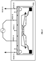
- FIG. 6 illustrates an example ToF measurement device 600, according to several embodiments of the presently disclosed devices and systems.
- the ToF measurement device 600 can be utilized to detect objects, e.g., as shown in target scene 602, as well as to determine distances to the detected objects.
- ToF measurement 600 may also be configured to determine reflectance values of the detected object or objects.
- ToF measurement device 600 may be a continuous-wave TOF system, such as a photon modulation device (PMD) -based TOF system.
- ToF measurement device 600 may be further configured to superimpose data on emitted light pulses, according to the techniques described herein, for reception by a remote device.
- PMD photon modulation device
- the illustrated ToF measurement device 600 includes a light source 624, which is configured to amplitude modulate a beam of light with a modulating signal and emit the amplitude-modulated light towards the scene 602.
- the amplitude modulation may be based on a reference signal generated by reference signal generator 608.
- the reference signal may be a radio-frequency (RF) signal, e.g., in the MHz range, although other modulation frequencies can be used.
- the emitted light can include light having varied ranges of wavelength, such as light in the visible spectrum or infra-red radiation. The emitted light reflects from one or more objects in the scene and returns to the sensor 604.
- the illustrated ToF measurement device 600 further includes a sensor 604, which comprises a plurality of pixels configured to generate a respective plurality of pixel signal values in response to received light 614, where each pixel is configured to obtain its respective pixel signal value by demodulating received light using a reference signal 622.
- received light 602 may be reflected from a target scene 602.
- one suitable pixel design is the PMD described above.
- the numbers of pixels, rows, and columns can vary, from one embodiment to another, and are selected based on factors including desired resolution, intensity, and the like. In one example, these sensor characteristics are selected based on the objects to be detected and the expected distances to the objects. Thus, for example, the pixel resolution of the pixels in sensor 604 may vary, from one embodiment to another. Small objects require a higher resolution for detection. For example, finger detection requires a resolution of ⁇ 5mm per pixel at a distance or range of about 0.5 meters. Medium sized objects, such as hand detection, require a resolution of ⁇ 20mm per pixel at a range of about 1.5 meters. Larger sized objects, such as a human body, require a resolution of ⁇ 60 mm per pixel at about 2.5 meters.
- ToF measurement device 600 further includes a reference signal generator 608, which may be configured, in some embodiments, to generate reference signal 622 with a selectable phase, relative to the phase of a modulation signal applied to light transmitted towards target scene 602, and to provide the reference signal 622 to the plurality of pixels in sensor 604.
- Image processing system 600 still further includes an analog-to-digital converter (ADC) circuit 606, which may include one or several ADCs, operatively coupled to the plurality of pixels in sensor 604, with ADC circuit 606 providing digital phase or distance measurements to reflectance map generator 610, which may comprise a separate processing circuit and/or digital logic and/or may be a functional unit implemented using the same circuitry making up control circuitry 612.
- ADC analog-to-digital converter
- the illustrated ToF measurement device 600 further includes control circuitry 612, which may comprise, for example a processor, controller, or the like, and/or other digital logic.
- the control circuitry 612 is configured to cause the image processing system 600 to carry out a method like those described above, in connection with Figure 5 .
- control circuity 612 may be configured to control the light source 624, the sensor 604, and reflectance map generator 610 to obtain a distance measurement to an object or material of interest, using one or more pixels in the sensor, and to obtain an intensity measurement corresponding to the distance measurement, using the one or more pixels.
- the intensity measurement and the distance measurement may be obtained at the same time, e.g., using multiple phase exposures of the object of interest.
- Control circuitry 612 may be further configured to control the reflectance map generator to calculate a reflectance value for the pixel, based on the distance measurement, the intensity measurement, and a reflectance calibration factor.
- This reflectance calibration factor may be pixel-specific, for instance, and may be obtained during a calibration process performed with ToF measurement device 600, for example, or provided to the ToF measurement 600.
- the reflectance value is calculated according to equation (3), above.
- control circuitry 612 and reflectance map generator 610 may be carried out for each of several (or many) pixels, e.g., for all of the pixels in sensor 604, with the results thus providing a reflectance map of the imaged object or objects.
- these reflectance values may be used in connection with a depth map and/or an RGB color map, for example, and/or in association with a 3D pointcloud. As indicated above, these reflectance values may be used to enhance object recognition or characterization, in various applications.
- ToF measurement device 600 may be further configured to carry out a calibration procedure.
- control circuitry 612 is configured to control the light source 624, the sensor 604, and reflectance map generator 610 to measure an intensity of reflection from a calibration surface for each of a plurality of pixels or groups of pixels and to measure the distance to the calibration surface, for each pixel or group of pixels - once again, it will be appreciated that the distance and intensity measurements may be performed at the same time, e.g., where both distance and intensity values are obtained from multiple exposures or phase images of the calibration surface.
- the control circuitry 612 may be further configured to control reflectance map generator 610 to scale the measured intensities, for each pixel or group of pixels, e.g., so as project the measured intensity onto a virtual sphere. This may be performed as a function of the viewing angle for the respective pixel or group of pixels, the measured distance to the calibration surface for the pixel or pixels, or both. Examples of this scaling operation are shown in equations (1a), (1b), and (1c), above. Control circuitry 612 in these embodiments may be further configured to control reflectance map generator 610 to calculate a reflectance calibration factor, for each pixel or group of pixels, as a function of a reference reflectance and the scaled measured intensity for the pixel or group of pixels.
- this reference reflectance may represent the actual reflectance of the calibration surface at a viewing angle of zero, but could instead represent an arbitrary factor for scaling intensity to a reflectance value, in some embodiments. This may be done according to equation (2) above, in some embodiments. Note that while Figure 5 (and the equations above) shows the scaling of the intensity measurement and the calculation of the reflectance calibration factor as two distinct operations, the reflectance calibration factor may be calculated in one step, in some embodiments, with the scaling of the intensity measurement being inherent in that calculation.
Landscapes
- Engineering & Computer Science (AREA)
- Physics & Mathematics (AREA)
- Computer Networks & Wireless Communication (AREA)
- General Physics & Mathematics (AREA)
- Radar, Positioning & Navigation (AREA)
- Remote Sensing (AREA)
- Electromagnetism (AREA)
- Measurement Of Optical Distance (AREA)
- Optical Radar Systems And Details Thereof (AREA)
- Length Measuring Devices By Optical Means (AREA)
Claims (16)
- Ein Verfahren in einer Laufzeitmessvorrichtung, ToF-Messvorrichtung, wobei das Verfahren Folgendes umfasst:Erhalten (550) einer Abstandsmessung unter Verwendung eines oder mehrerer Pixel in einem ToF-Sensor;Erhalten (560) einer Intensitätsmessung, die der Abstandsmessung entspricht, unter Verwendung des einen oder der mehreren Pixel; undBerechnen (570) eines Reflexionswerts für das eine oder die mehreren Pixel basierend auf der Abstandsmessung, der Intensitätsmessung und einem Reflexionskalibrierungsfaktor, dadurch gekennzeichnet, dass der Reflexionskalibrierungsfaktor für zumindest eines von einem Betrachtungswinkel für das eine oder die mehreren Pixel unter Verwendung des Lambertschen Kosinusgesetzes und einer Differenz zwischen einem Abstand zu einer planaren, diffusen Kalibrierungsoberfläche, die durch das eine oder die mehreren Pixel gemessen wird, und einem Abstandskalibrierungswert unter Verwendung des inversen quadratischen Gesetzes kompensiert wird.
- Verfahren nach Anspruch 1, wobei der Reflexionskalibrierungsfaktor für das eine oder die mehreren Pixel in dem ToF-Sensor spezifisch ist.
- Eine Laufzeitmessvorrichtung, ToF-Messvorrichtung (600), die Folgendes umfasst:eine Lichtquelle (624), die konfiguriert ist, um eine Reihe von Lichtimpulsen zu emittieren, die durch Amplitudenmodulieren von Licht mit einem Modulationssignal gebildet werden;einen ToF-Sensor (604), der eine Mehrzahl von Pixeln umfasst, die konfiguriert sind, um eine jeweilige Mehrzahl von Pixelsignalwerten als Reaktion auf empfangenes Licht zu erzeugen, wobei jedes Pixel konfiguriert ist, um seinen jeweiligen Pixelsignalwert durch Demodulieren von empfangenem Licht unter Verwendung eines Referenzsignals zu erhalten;einen Referenzsignalgenerator (608), der konfiguriert ist, um das Referenzsignal zu erzeugen und das Referenzsignal an die Mehrzahl von Pixeln bereitzustellen; undeine Steuerschaltungsanordnung (612), die konfiguriert ist, um die Lichtquelle, den ToF-Sensor und einen Reflexionskartengenerator zu Folgendem zu steuern:Erhalten einer Abstandsmessung unter Verwendung eines oder mehrerer Pixel in dem ToF-Sensor;Erhalten einer Intensitätsmessung, die der Abstandsmessung entspricht, unter Verwendung des einen oder der mehreren Pixel; undBerechnen eines Reflexionswerts für das eine oder die mehreren Pixel basierend auf der Abstandsmessung, der Intensitätsmessung und einem Reflexionskalibrierungsfaktor, dadurch gekennzeichnet, dass der Reflexionskalibrierungsfaktor für zumindest eines von einem Betrachtungswinkel für das eine oder die mehreren Pixel unter Verwendung des Lambertschen Kosinusgesetzes und einer Differenz zwischen einem Abstand zu einer planaren, diffusen Kalibrierungsoberfläche, die durch das eine oder die mehreren Pixel gemessen wird, und einem Abstandskalibrierungswert unter Verwendung des inversen quadratischen Gesetzes kompensiert wird.
- ToF-Messvorrichtung nach Anspruch 3, wobei der Reflexionskalibrierungsfaktor für ein oder mehrere Pixel in dem ToF-Sensor spezifisch ist.
- ToF-Messvorrichtung nach Anspruch 3 oder 4, wobei der Reflexionswert durch Multiplizieren der Intensitätsmessung mit dem Reflexionskalibrierungsfaktor und mit einem Faktor proportional zu dem Quadrat der Abstandsmessung berechnet wird.
- ToF-Messvorrichtung nach einem der Ansprüche 3 bis 5, wobei der Reflexionswert berechnet wird gemäß:

- ToF-Messvorrichtung nach einem der Ansprüche 3 bis 6,
wobei die Steuerschaltungsanordnung (612) konfiguriert ist, um die Lichtquelle (624), den ToF-Sensor (604) und den Reflexionskartengenerator (610) zu Folgendem zu steuern:Erhalten einer Mehrzahl von Abstandsmessungen unter Verwendung des ToF-Sensors, wobei jede Abstandsmessung unter Verwendung einer jeweiligen Gruppe von Pixeln in dem ToF-Sensor erhalten wird;Erhalten einer Intensitätsmessung, die jeder der Abstandsmessungen entspricht, unter Verwendung der jeweiligen Gruppen von Pixeln; undBerechnen eines Reflexionswerts, der jeder Intensitätsmessung entspricht, basierend auf der Intensitätsmessung, der jeweiligen Abstandsmessung und einem jeweiligen Reflexionskalibrierungsfaktor. - ToF-Messvorrichtung nach Anspruch 7, wobei die Steuerschaltungsanordnung (312) konfiguriert ist, um jeweilige Reflexionskalibrierungsfaktoren zu erhalten, wobei die jeweiligen Kalibrierungsfaktoren jeweils für eine jeweilige Gruppe von Pixeln spezifisch sind.
- ToF-Messvorrichtung nach Anspruch 7 oder 8, wobei für jede jeweilige Gruppe von Pixeln der Reflexionswert durch Multiplizieren der Intensitätsmessung für die jeweilige Gruppe von Pixeln mit dem Reflexionskalibrierungsfaktor für die jeweilige Gruppe von Pixeln und mit einem Faktor proportional zu dem Quadrat der Abstandsmessung für die jeweilige Gruppe von Pixeln berechnet wird.
- ToF-Messvorrichtung nach einem der Ansprüche 7-9, wobei der Reflexionswert für jedes Pixel i, j berechnet wird gemäß:
 Ri,j der berechnete Reflexionswert für Pixel i, j ist;ci,j der Reflexionskalibrierungsfaktor für Pixel i, j ist;Ii,j die gemessene Intensität für Pixel i, j ist;di,j die Abstandsmessung für Pixel i, j ist; unddcalib ein Kalibrierungsabstand ist.
 - ToF-Messvorrichtung nach einem der Ansprüche 7-10, wobei die Steuerschaltungsanordnung (612) konfiguriert ist, um die Lichtquelle (624), den TOF-Sensor (604) und den Reflexionskartengenerator (610) zu steuern, um einen Referenzabstand zu einer Kalibrierungsoberfläche unter Verwendung eines Referenzpixels in dem ToF-Sensor (604) zu messen und den Kalibrierungsabstand aus dem gemessenen Referenzabstand zu erhalten.
- ToF-Messvorrichtung nach einem der Ansprüche 7-11, wobei die Steuerschaltungsanordnung (612) konfiguriert ist, um die Lichtquelle (624), den TOF-Sensor (604) und den Reflexionskartengenerator (610) zu steuern, um den Reflexionskalibrierungsfaktor durch Folgendes zu erhalten:
Berechnen des Reflexionskalibrierungsfaktors für jede der jeweiligen Gruppen von Pixeln als eine Funktion eines Betrachtungswinkels für die Gruppe von Pixeln oder eines Abstands zu einer Kalibrierungsoberfläche, die durch das Pixel oder die Gruppe von Pixeln oder beides gemessen wird, und einer Referenzreflexion. - ToF-Messvorrichtung nach Anspruch 12, wobei die Funktion eine Funktion von Rref / cos βi,j ist, wobei Rref die Referenzreflexion ist und βi,j der Betrachtungswinkel der jeweiligen Gruppe von Pixeln in Bezug auf die optische Achse des ToF-Sensors (604) ist.
- ToF-Messvorrichtung nach einem der Ansprüche 7 bis 13, wobei die Steuerschaltungsanordnung (612) konfiguriert ist, um die Lichtquelle (624), den TOF-Sensor (604) und den Reflexionskartengenerator (610) zu steuern, um die Reflexionskalibrierungsfaktoren durch Folgendes für jede Gruppe von Pixeln zu erhalten:Messen einer Intensität der Reflexion von einer Kalibrierungsoberfläche unter Verwendung der Gruppe von Pixeln;Skalieren der gemessenen Intensität basierend auf dem Betrachtungswinkel für die Gruppe von Pixeln in Bezug auf die optische Achse des ToF-Sensors;Berechnen des Reflexionskalibrierungsfaktors für die Gruppe von Pixeln durch Multiplizieren eines Inversen der skalierten gemessenen Intensität und einer Referenzreflexion.
- ToF-Messvorrichtung nach Anspruch 14, wobei das Skalieren der gemessenen Intensität das Berechnen der skalierten gemessenen Intensität gemäß Li,j = Ii,j / (cos β i,j )3 umfasst, wobei:Li,j die skalierte gemessene Intensität für Pixel i, j ist;Ii,j die gemessene Intensität für Pixel i, j ist; undβi,j der Betrachtungswinkel von Pixel i, j in Bezug auf die optische Achse des ToF-Sensors ist.
- ToF-Messvorrichtung nach Anspruch 14 oder 15, wobei die Steuerschaltungsanordnung (612) konfiguriert ist, um die Lichtquelle (624), den TOF-Sensor (604) und den Reflexionskartengenerator (610) zu steuern, um einen Abstand zu der Kalibrierungsoberfläche für jede Gruppe von Pixeln zu messen und die gemessene Intensität durch Berechnen der skalierten gemessenen Intensität gemäß
 Li,j die skalierte gemessene Intensität für Pixel i, j ist;Ii,j die gemessene Intensität für Pixel i, j ist;dci,j der gemessene Abstand zu der Kalibrierungsoberfläche für Pixel i, j ist;βi,j der Betrachtungswinkel von Pixel i, j in Bezug auf die optische Achse des ToF-Sensors ist; unddcalib der Kalibrierungsabstand ist.
Applications Claiming Priority (1)
| Application Number | Priority Date | Filing Date | Title |
|---|---|---|---|
| US16/414,969 US11874403B2 (en) | 2019-05-17 | 2019-05-17 | Reflectance sensing with time-of-flight cameras |
Publications (2)
| Publication Number | Publication Date |
|---|---|
| EP3739362A1 EP3739362A1 (de) | 2020-11-18 |
| EP3739362B1 true EP3739362B1 (de) | 2024-09-04 |
Family
ID=70736710
Family Applications (1)
| Application Number | Title | Priority Date | Filing Date |
|---|---|---|---|
| EP20174659.1A Active EP3739362B1 (de) | 2019-05-17 | 2020-05-14 | Reflektanzmessung mit flugzeitkameras |
Country Status (3)
| Country | Link |
|---|---|
| US (1) | US11874403B2 (de) |
| EP (1) | EP3739362B1 (de) |
| CN (1) | CN112034485B (de) |
Families Citing this family (10)
| Publication number | Priority date | Publication date | Assignee | Title |
|---|---|---|---|---|
| JP7420038B2 (ja) * | 2019-10-16 | 2024-01-23 | 株式会社デンソー | 車載の異常検出装置 |
| EP4081830A1 (de) * | 2019-12-23 | 2022-11-02 | Sony Semiconductor Solutions Corporation | Flugzeitobjektdetektionsschaltung und flugzeitobjektdetektionsverfahren |
| KR20220141006A (ko) * | 2021-04-12 | 2022-10-19 | 에스케이하이닉스 주식회사 | 촬영 장치 |
| CN115239802A (zh) * | 2021-04-23 | 2022-10-25 | 阿里巴巴新加坡控股有限公司 | 数据处理方法、装置和货品摆放的调整方法 |
| CN114302067B (zh) * | 2021-12-30 | 2025-02-11 | 无锡图创智能科技有限公司 | 不同反射率表面三维结构光测量的曝光值选择方法 |
| US20230367010A1 (en) * | 2022-01-24 | 2023-11-16 | Sensortek Technology Corp. | Light sensor and control method thereof |
| JP2024024329A (ja) * | 2022-08-09 | 2024-02-22 | 上海天馬微電子有限公司 | センサ装置及び補正係数を決定する方法 |
| CN115844334B (zh) * | 2022-12-19 | 2024-05-28 | 哈尔滨工业大学 | 一种基于物理过程的间接型ToF相机对人体皮肤组织深度测量值误差的获取方法 |
| CN117054047B (zh) * | 2023-10-11 | 2023-12-22 | 泰州市银杏舞台机械工程有限公司 | 一种基于检测灯内板偏转的舞台灯检测方法及系统 |
| US20250272865A1 (en) * | 2024-02-23 | 2025-08-28 | Zebra Technologies Corporation | Image-Assisted Material Classification for Mobile Dimensioning |
Family Cites Families (10)
| Publication number | Priority date | Publication date | Assignee | Title |
|---|---|---|---|---|
| CN103261912B (zh) * | 2010-07-29 | 2016-01-20 | 威凯托陵科有限公司 | 用于测量对象的距离和/或强度特性的设备和方法 |
| KR20140057625A (ko) * | 2012-01-10 | 2014-05-13 | 소프트키네틱 센서스 엔브이 | 이동거리시간차 신호들을 프로세싱하는데 있어서 또는 프로세싱과 관련된 개선들 |
| CN105026955B (zh) * | 2012-12-28 | 2018-12-18 | 诺基亚技术有限公司 | 用于对来自距离感应相机的数据进行降噪的方法和装置 |
| US10063844B2 (en) * | 2013-10-17 | 2018-08-28 | Microsoft Technology Licensing, Llc. | Determining distances by probabilistic time of flight imaging |
| US9823352B2 (en) * | 2014-10-31 | 2017-11-21 | Rockwell Automation Safety Ag | Absolute distance measurement for time-of-flight sensors |
| US9958383B2 (en) | 2014-12-18 | 2018-05-01 | Microsoft Technology Licensing, Llc. | Range camera |
| DE102016219516B4 (de) * | 2015-10-30 | 2021-11-04 | pmdtechnologies ag | Lichtlaufzeitkamerasystem |
| EP3508814B1 (de) * | 2016-09-01 | 2023-08-23 | Sony Semiconductor Solutions Corporation | Bildgebungsvorrichtung |
| KR102618542B1 (ko) * | 2016-09-07 | 2023-12-27 | 삼성전자주식회사 | ToF (time of flight) 촬영 장치 및 ToF 촬영 장치에서 깊이 이미지의 블러 감소를 위하여 이미지를 처리하는 방법 |
| US20180278910A1 (en) * | 2017-03-22 | 2018-09-27 | Microsoft Technology Licensing, Llc | Correction of multipath interference in time of flight camera depth imaging measurements |
-
2019
- 2019-05-17 US US16/414,969 patent/US11874403B2/en active Active
-
2020
- 2020-05-14 EP EP20174659.1A patent/EP3739362B1/de active Active
- 2020-05-15 CN CN202010414786.7A patent/CN112034485B/zh active Active
Also Published As
| Publication number | Publication date |
|---|---|
| US20200363512A1 (en) | 2020-11-19 |
| EP3739362A1 (de) | 2020-11-18 |
| CN112034485B (zh) | 2025-08-01 |
| US11874403B2 (en) | 2024-01-16 |
| CN112034485A (zh) | 2020-12-04 |
Similar Documents
| Publication | Publication Date | Title |
|---|---|---|
| EP3739362B1 (de) | Reflektanzmessung mit flugzeitkameras | |
| US11536804B2 (en) | Glare mitigation in LIDAR applications | |
| Kahlmann et al. | Calibration for increased accuracy of the range imaging camera swissranger | |
| US10091492B2 (en) | Imaging apparatuses and a time of flight imaging method | |
| US10677923B2 (en) | Optoelectronic modules for distance measurements and/or multi-dimensional imaging | |
| US10643349B2 (en) | Method of calibrating a camera and a laser scanner | |
| US11393115B2 (en) | Filtering continuous-wave time-of-flight measurements, based on coded modulation images | |
| WO2020023489A1 (en) | Phase noise and methods of correction in multi-frequency mode lidar | |
| JP7259660B2 (ja) | イメージレジストレーション装置、画像生成システム及びイメージレジストレーションプログラム | |
| TW201539011A (zh) | 可操作以辨認偽反射及補償由偽反射所造成之錯誤的光電模組 | |
| CN113780349A (zh) | 训练样本集的获取方法、模型训练方法及相关装置 | |
| US11506763B2 (en) | Image sensor with interleaved hold for single-readout depth measurement | |
| EP3712639B1 (de) | Gleichzeitige datenübertragung und tiefenbildaufzeichnung mit flugzeitkameras | |
| CN112945221A (zh) | 相位角校正值计算装置和计算相位角校正值的方法 | |
| Liu et al. | Intensity image-based LiDAR fiducial marker system | |
| Mohammed et al. | The effect of polynomial order on georeferencing remote sensing images | |
| CN105518483A (zh) | 散射光参考像素 | |
| Langmann | Wide area 2D/3D imaging: development, analysis and applications | |
| CN207515908U (zh) | 一种多光路自定标偏振探测装置及系统 | |
| Dorrington et al. | An evaluation of time-of-flight range cameras for close range metrology applications | |
| Robbins et al. | Photogrammetric calibration and colorization of the SwissRanger SR-3100 3-D range imaging sensor | |
| Zhang et al. | Method of improving the measurement accuracy of plane array imaging laser radar by pixel cascade | |
| EP4685518A1 (de) | Vorrichtung und verfahren, vorrichtung und verfahren zur bestimmung eines referenzwertes zur anzeige einer parallaxe und flugzeitsystem | |
| Peppa | Precision analysis of 3D camera | |
| Liu et al. | Establishment and verification of energy simulation model of time-of-flight depth camera |
Legal Events
| Date | Code | Title | Description |
|---|---|---|---|
| PUAI | Public reference made under article 153(3) epc to a published international application that has entered the european phase |
Free format text: ORIGINAL CODE: 0009012 |
|
| STAA | Information on the status of an ep patent application or granted ep patent |
Free format text: STATUS: THE APPLICATION HAS BEEN PUBLISHED |
|
| AK | Designated contracting states |
Kind code of ref document: A1 Designated state(s): AL AT BE BG CH CY CZ DE DK EE ES FI FR GB GR HR HU IE IS IT LI LT LU LV MC MK MT NL NO PL PT RO RS SE SI SK SM TR |
|
| AX | Request for extension of the european patent |
Extension state: BA ME |
|
| STAA | Information on the status of an ep patent application or granted ep patent |
Free format text: STATUS: REQUEST FOR EXAMINATION WAS MADE |
|
| 17P | Request for examination filed |
Effective date: 20210512 |
|
| RBV | Designated contracting states (corrected) |
Designated state(s): AL AT BE BG CH CY CZ DE DK EE ES FI FR GB GR HR HU IE IS IT LI LT LU LV MC MK MT NL NO PL PT RO RS SE SI SK SM TR |
|
| STAA | Information on the status of an ep patent application or granted ep patent |
Free format text: STATUS: EXAMINATION IS IN PROGRESS |
|
| 17Q | First examination report despatched |
Effective date: 20221205 |
|
| GRAP | Despatch of communication of intention to grant a patent |
Free format text: ORIGINAL CODE: EPIDOSNIGR1 |
|
| STAA | Information on the status of an ep patent application or granted ep patent |
Free format text: STATUS: GRANT OF PATENT IS INTENDED |
|
| INTG | Intention to grant announced |
Effective date: 20240405 |
|
| GRAS | Grant fee paid |
Free format text: ORIGINAL CODE: EPIDOSNIGR3 |
|
| GRAA | (expected) grant |
Free format text: ORIGINAL CODE: 0009210 |
|
| STAA | Information on the status of an ep patent application or granted ep patent |
Free format text: STATUS: THE PATENT HAS BEEN GRANTED |
|
| P01 | Opt-out of the competence of the unified patent court (upc) registered |
Free format text: CASE NUMBER: APP_39161/2024 Effective date: 20240701 |
|
| AK | Designated contracting states |
Kind code of ref document: B1 Designated state(s): AL AT BE BG CH CY CZ DE DK EE ES FI FR GB GR HR HU IE IS IT LI LT LU LV MC MK MT NL NO PL PT RO RS SE SI SK SM TR |
|
| REG | Reference to a national code |
Ref country code: GB Ref legal event code: FG4D |
|
| REG | Reference to a national code |
Ref country code: CH Ref legal event code: EP |
|
| REG | Reference to a national code |
Ref country code: IE Ref legal event code: FG4D |
|
| REG | Reference to a national code |
Ref country code: DE Ref legal event code: R096 Ref document number: 602020036920 Country of ref document: DE |
|
| REG | Reference to a national code |
Ref country code: LT Ref legal event code: MG9D |
|
| REG | Reference to a national code |
Ref country code: NL Ref legal event code: MP Effective date: 20240904 |
|
| PG25 | Lapsed in a contracting state [announced via postgrant information from national office to epo] |
Ref country code: NO Free format text: LAPSE BECAUSE OF FAILURE TO SUBMIT A TRANSLATION OF THE DESCRIPTION OR TO PAY THE FEE WITHIN THE PRESCRIBED TIME-LIMIT Effective date: 20241204 |
|
| PG25 | Lapsed in a contracting state [announced via postgrant information from national office to epo] |
Ref country code: PL Free format text: LAPSE BECAUSE OF FAILURE TO SUBMIT A TRANSLATION OF THE DESCRIPTION OR TO PAY THE FEE WITHIN THE PRESCRIBED TIME-LIMIT Effective date: 20240904 Ref country code: GR Free format text: LAPSE BECAUSE OF FAILURE TO SUBMIT A TRANSLATION OF THE DESCRIPTION OR TO PAY THE FEE WITHIN THE PRESCRIBED TIME-LIMIT Effective date: 20241205 Ref country code: FI Free format text: LAPSE BECAUSE OF FAILURE TO SUBMIT A TRANSLATION OF THE DESCRIPTION OR TO PAY THE FEE WITHIN THE PRESCRIBED TIME-LIMIT Effective date: 20240904 |
|
| PG25 | Lapsed in a contracting state [announced via postgrant information from national office to epo] |
Ref country code: BG Free format text: LAPSE BECAUSE OF FAILURE TO SUBMIT A TRANSLATION OF THE DESCRIPTION OR TO PAY THE FEE WITHIN THE PRESCRIBED TIME-LIMIT Effective date: 20240904 |
|
| PG25 | Lapsed in a contracting state [announced via postgrant information from national office to epo] |
Ref country code: LV Free format text: LAPSE BECAUSE OF FAILURE TO SUBMIT A TRANSLATION OF THE DESCRIPTION OR TO PAY THE FEE WITHIN THE PRESCRIBED TIME-LIMIT Effective date: 20240904 |
|
| PG25 | Lapsed in a contracting state [announced via postgrant information from national office to epo] |
Ref country code: HR Free format text: LAPSE BECAUSE OF FAILURE TO SUBMIT A TRANSLATION OF THE DESCRIPTION OR TO PAY THE FEE WITHIN THE PRESCRIBED TIME-LIMIT Effective date: 20240904 |
|
| PG25 | Lapsed in a contracting state [announced via postgrant information from national office to epo] |
Ref country code: ES Free format text: LAPSE BECAUSE OF FAILURE TO SUBMIT A TRANSLATION OF THE DESCRIPTION OR TO PAY THE FEE WITHIN THE PRESCRIBED TIME-LIMIT Effective date: 20240904 Ref country code: RS Free format text: LAPSE BECAUSE OF FAILURE TO SUBMIT A TRANSLATION OF THE DESCRIPTION OR TO PAY THE FEE WITHIN THE PRESCRIBED TIME-LIMIT Effective date: 20241204 |
|
| PG25 | Lapsed in a contracting state [announced via postgrant information from national office to epo] |
Ref country code: RS Free format text: LAPSE BECAUSE OF FAILURE TO SUBMIT A TRANSLATION OF THE DESCRIPTION OR TO PAY THE FEE WITHIN THE PRESCRIBED TIME-LIMIT Effective date: 20241204 Ref country code: PL Free format text: LAPSE BECAUSE OF FAILURE TO SUBMIT A TRANSLATION OF THE DESCRIPTION OR TO PAY THE FEE WITHIN THE PRESCRIBED TIME-LIMIT Effective date: 20240904 Ref country code: NO Free format text: LAPSE BECAUSE OF FAILURE TO SUBMIT A TRANSLATION OF THE DESCRIPTION OR TO PAY THE FEE WITHIN THE PRESCRIBED TIME-LIMIT Effective date: 20241204 Ref country code: LV Free format text: LAPSE BECAUSE OF FAILURE TO SUBMIT A TRANSLATION OF THE DESCRIPTION OR TO PAY THE FEE WITHIN THE PRESCRIBED TIME-LIMIT Effective date: 20240904 Ref country code: HR Free format text: LAPSE BECAUSE OF FAILURE TO SUBMIT A TRANSLATION OF THE DESCRIPTION OR TO PAY THE FEE WITHIN THE PRESCRIBED TIME-LIMIT Effective date: 20240904 Ref country code: GR Free format text: LAPSE BECAUSE OF FAILURE TO SUBMIT A TRANSLATION OF THE DESCRIPTION OR TO PAY THE FEE WITHIN THE PRESCRIBED TIME-LIMIT Effective date: 20241205 Ref country code: FI Free format text: LAPSE BECAUSE OF FAILURE TO SUBMIT A TRANSLATION OF THE DESCRIPTION OR TO PAY THE FEE WITHIN THE PRESCRIBED TIME-LIMIT Effective date: 20240904 Ref country code: ES Free format text: LAPSE BECAUSE OF FAILURE TO SUBMIT A TRANSLATION OF THE DESCRIPTION OR TO PAY THE FEE WITHIN THE PRESCRIBED TIME-LIMIT Effective date: 20240904 Ref country code: BG Free format text: LAPSE BECAUSE OF FAILURE TO SUBMIT A TRANSLATION OF THE DESCRIPTION OR TO PAY THE FEE WITHIN THE PRESCRIBED TIME-LIMIT Effective date: 20240904 |
|
| REG | Reference to a national code |
Ref country code: AT Ref legal event code: MK05 Ref document number: 1720941 Country of ref document: AT Kind code of ref document: T Effective date: 20240904 |
|
| PG25 | Lapsed in a contracting state [announced via postgrant information from national office to epo] |
Ref country code: NL Free format text: LAPSE BECAUSE OF FAILURE TO SUBMIT A TRANSLATION OF THE DESCRIPTION OR TO PAY THE FEE WITHIN THE PRESCRIBED TIME-LIMIT Effective date: 20240904 |
|
| PG25 | Lapsed in a contracting state [announced via postgrant information from national office to epo] |
Ref country code: IS Free format text: LAPSE BECAUSE OF FAILURE TO SUBMIT A TRANSLATION OF THE DESCRIPTION OR TO PAY THE FEE WITHIN THE PRESCRIBED TIME-LIMIT Effective date: 20250104 Ref country code: PT Free format text: LAPSE BECAUSE OF FAILURE TO SUBMIT A TRANSLATION OF THE DESCRIPTION OR TO PAY THE FEE WITHIN THE PRESCRIBED TIME-LIMIT Effective date: 20250106 |
|
| PG25 | Lapsed in a contracting state [announced via postgrant information from national office to epo] |
Ref country code: SM Free format text: LAPSE BECAUSE OF FAILURE TO SUBMIT A TRANSLATION OF THE DESCRIPTION OR TO PAY THE FEE WITHIN THE PRESCRIBED TIME-LIMIT Effective date: 20240904 Ref country code: RO Free format text: LAPSE BECAUSE OF FAILURE TO SUBMIT A TRANSLATION OF THE DESCRIPTION OR TO PAY THE FEE WITHIN THE PRESCRIBED TIME-LIMIT Effective date: 20240904 |
|
| PG25 | Lapsed in a contracting state [announced via postgrant information from national office to epo] |
Ref country code: EE Free format text: LAPSE BECAUSE OF FAILURE TO SUBMIT A TRANSLATION OF THE DESCRIPTION OR TO PAY THE FEE WITHIN THE PRESCRIBED TIME-LIMIT Effective date: 20240904 Ref country code: AT Free format text: LAPSE BECAUSE OF FAILURE TO SUBMIT A TRANSLATION OF THE DESCRIPTION OR TO PAY THE FEE WITHIN THE PRESCRIBED TIME-LIMIT Effective date: 20240904 |
|
| PG25 | Lapsed in a contracting state [announced via postgrant information from national office to epo] |
Ref country code: CZ Free format text: LAPSE BECAUSE OF FAILURE TO SUBMIT A TRANSLATION OF THE DESCRIPTION OR TO PAY THE FEE WITHIN THE PRESCRIBED TIME-LIMIT Effective date: 20240904 |
|
| PG25 | Lapsed in a contracting state [announced via postgrant information from national office to epo] |
Ref country code: IT Free format text: LAPSE BECAUSE OF FAILURE TO SUBMIT A TRANSLATION OF THE DESCRIPTION OR TO PAY THE FEE WITHIN THE PRESCRIBED TIME-LIMIT Effective date: 20240904 Ref country code: SK Free format text: LAPSE BECAUSE OF FAILURE TO SUBMIT A TRANSLATION OF THE DESCRIPTION OR TO PAY THE FEE WITHIN THE PRESCRIBED TIME-LIMIT Effective date: 20240904 |
|
| REG | Reference to a national code |
Ref country code: DE Ref legal event code: R097 Ref document number: 602020036920 Country of ref document: DE |
|
| PG25 | Lapsed in a contracting state [announced via postgrant information from national office to epo] |
Ref country code: DK Free format text: LAPSE BECAUSE OF FAILURE TO SUBMIT A TRANSLATION OF THE DESCRIPTION OR TO PAY THE FEE WITHIN THE PRESCRIBED TIME-LIMIT Effective date: 20240904 |
|
| PGFP | Annual fee paid to national office [announced via postgrant information from national office to epo] |
Ref country code: GB Payment date: 20250527 Year of fee payment: 6 |
|
| PLBE | No opposition filed within time limit |
Free format text: ORIGINAL CODE: 0009261 |
|
| STAA | Information on the status of an ep patent application or granted ep patent |
Free format text: STATUS: NO OPPOSITION FILED WITHIN TIME LIMIT |
|
| PGFP | Annual fee paid to national office [announced via postgrant information from national office to epo] |
Ref country code: FR Payment date: 20250528 Year of fee payment: 6 |
|
| 26N | No opposition filed |
Effective date: 20250605 |
|
| PG25 | Lapsed in a contracting state [announced via postgrant information from national office to epo] |
Ref country code: SE Free format text: LAPSE BECAUSE OF FAILURE TO SUBMIT A TRANSLATION OF THE DESCRIPTION OR TO PAY THE FEE WITHIN THE PRESCRIBED TIME-LIMIT Effective date: 20240904 |
|
| PGFP | Annual fee paid to national office [announced via postgrant information from national office to epo] |
Ref country code: DE Payment date: 20250721 Year of fee payment: 6 |
|
| REG | Reference to a national code |
Ref country code: CH Ref legal event code: H13 Free format text: ST27 STATUS EVENT CODE: U-0-0-H10-H13 (AS PROVIDED BY THE NATIONAL OFFICE) Effective date: 20251223 |
|
| PG25 | Lapsed in a contracting state [announced via postgrant information from national office to epo] |
Ref country code: LU Free format text: LAPSE BECAUSE OF NON-PAYMENT OF DUE FEES Effective date: 20250514 |
|
| PG25 | Lapsed in a contracting state [announced via postgrant information from national office to epo] |
Ref country code: CH Free format text: LAPSE BECAUSE OF NON-PAYMENT OF DUE FEES Effective date: 20250531 |
|
| REG | Reference to a national code |
Ref country code: BE Ref legal event code: MM Effective date: 20250531 |
|
| PG25 | Lapsed in a contracting state [announced via postgrant information from national office to epo] |
Ref country code: MC Free format text: LAPSE BECAUSE OF FAILURE TO SUBMIT A TRANSLATION OF THE DESCRIPTION OR TO PAY THE FEE WITHIN THE PRESCRIBED TIME-LIMIT Effective date: 20240904 |
|
| PG25 | Lapsed in a contracting state [announced via postgrant information from national office to epo] |
Ref country code: IE Free format text: LAPSE BECAUSE OF NON-PAYMENT OF DUE FEES Effective date: 20250514 |
|
| PG25 | Lapsed in a contracting state [announced via postgrant information from national office to epo] |
Ref country code: BE Free format text: LAPSE BECAUSE OF NON-PAYMENT OF DUE FEES Effective date: 20250531 |