EP3739317A1 - Pressure sensor device - Google Patents
Pressure sensor device Download PDFInfo
- Publication number
- EP3739317A1 EP3739317A1 EP19755059.3A EP19755059A EP3739317A1 EP 3739317 A1 EP3739317 A1 EP 3739317A1 EP 19755059 A EP19755059 A EP 19755059A EP 3739317 A1 EP3739317 A1 EP 3739317A1
- Authority
- EP
- European Patent Office
- Prior art keywords
- board
- pressure sensor
- sensor device
- hole
- hollow part
- Prior art date
- Legal status (The legal status is an assumption and is not a legal conclusion. Google has not performed a legal analysis and makes no representation as to the accuracy of the status listed.)
- Granted
Links
Images











Classifications
-
- G—PHYSICS
- G01—MEASURING; TESTING
- G01L—MEASURING FORCE, STRESS, TORQUE, WORK, MECHANICAL POWER, MECHANICAL EFFICIENCY, OR FLUID PRESSURE
- G01L13/00—Devices or apparatus for measuring differences of two or more fluid pressure values
- G01L13/02—Devices or apparatus for measuring differences of two or more fluid pressure values using elastically-deformable members or pistons as sensing elements
- G01L13/025—Devices or apparatus for measuring differences of two or more fluid pressure values using elastically-deformable members or pistons as sensing elements using diaphragms
-
- G—PHYSICS
- G01—MEASURING; TESTING
- G01L—MEASURING FORCE, STRESS, TORQUE, WORK, MECHANICAL POWER, MECHANICAL EFFICIENCY, OR FLUID PRESSURE
- G01L9/00—Measuring steady of quasi-steady pressure of fluid or fluent solid material by electric or magnetic pressure-sensitive elements; Transmitting or indicating the displacement of mechanical pressure-sensitive elements, used to measure the steady or quasi-steady pressure of a fluid or fluent solid material, by electric or magnetic means
- G01L9/0041—Transmitting or indicating the displacement of flexible diaphragms
- G01L9/0072—Transmitting or indicating the displacement of flexible diaphragms using variations in capacitance
-
- G—PHYSICS
- G01—MEASURING; TESTING
- G01L—MEASURING FORCE, STRESS, TORQUE, WORK, MECHANICAL POWER, MECHANICAL EFFICIENCY, OR FLUID PRESSURE
- G01L19/00—Details of, or accessories for, apparatus for measuring steady or quasi-steady pressure of a fluent medium insofar as such details or accessories are not special to particular types of pressure gauges
-
- G—PHYSICS
- G01—MEASURING; TESTING
- G01L—MEASURING FORCE, STRESS, TORQUE, WORK, MECHANICAL POWER, MECHANICAL EFFICIENCY, OR FLUID PRESSURE
- G01L19/00—Details of, or accessories for, apparatus for measuring steady or quasi-steady pressure of a fluent medium insofar as such details or accessories are not special to particular types of pressure gauges
- G01L19/0007—Fluidic connecting means
-
- G—PHYSICS
- G01—MEASURING; TESTING
- G01L—MEASURING FORCE, STRESS, TORQUE, WORK, MECHANICAL POWER, MECHANICAL EFFICIENCY, OR FLUID PRESSURE
- G01L19/00—Details of, or accessories for, apparatus for measuring steady or quasi-steady pressure of a fluent medium insofar as such details or accessories are not special to particular types of pressure gauges
- G01L19/0007—Fluidic connecting means
- G01L19/0038—Fluidic connecting means being part of the housing
-
- G—PHYSICS
- G01—MEASURING; TESTING
- G01L—MEASURING FORCE, STRESS, TORQUE, WORK, MECHANICAL POWER, MECHANICAL EFFICIENCY, OR FLUID PRESSURE
- G01L19/00—Details of, or accessories for, apparatus for measuring steady or quasi-steady pressure of a fluent medium insofar as such details or accessories are not special to particular types of pressure gauges
- G01L19/14—Housings
- G01L19/142—Multiple part housings
- G01L19/143—Two part housings
-
- G—PHYSICS
- G01—MEASURING; TESTING
- G01L—MEASURING FORCE, STRESS, TORQUE, WORK, MECHANICAL POWER, MECHANICAL EFFICIENCY, OR FLUID PRESSURE
- G01L9/00—Measuring steady of quasi-steady pressure of fluid or fluent solid material by electric or magnetic pressure-sensitive elements; Transmitting or indicating the displacement of mechanical pressure-sensitive elements, used to measure the steady or quasi-steady pressure of a fluid or fluent solid material, by electric or magnetic means
- G01L9/0041—Transmitting or indicating the displacement of flexible diaphragms
- G01L9/0042—Constructional details associated with semiconductive diaphragm sensors, e.g. etching, or constructional details of non-semiconductive diaphragms
-
- G—PHYSICS
- G01—MEASURING; TESTING
- G01L—MEASURING FORCE, STRESS, TORQUE, WORK, MECHANICAL POWER, MECHANICAL EFFICIENCY, OR FLUID PRESSURE
- G01L9/00—Measuring steady of quasi-steady pressure of fluid or fluent solid material by electric or magnetic pressure-sensitive elements; Transmitting or indicating the displacement of mechanical pressure-sensitive elements, used to measure the steady or quasi-steady pressure of a fluid or fluent solid material, by electric or magnetic means
- G01L9/0041—Transmitting or indicating the displacement of flexible diaphragms
- G01L9/0051—Transmitting or indicating the displacement of flexible diaphragms using variations in ohmic resistance
Definitions
- the present invention relates to a pressure sensor device including a semiconductor pressure sensor element.
- a pressure sensor device includes a semiconductor pressure sensor element, and has a packaged configuration including a pressure inlet for introducing a fluid as a measurement target and an air inlet for introducing air as a comparison target.
- the semiconductor pressure sensor element is a chip that has a structure where a piezoelectric element is provided on the surface of a diaphragm deformable by the pressures of the introduced fluid and the introduced air, and detects the pressure of the fluid relative to the atmospheric pressure.
- the pressure sensor device when the atmospheric pressure is used as the comparison target pressure, the pressure sensor device is configured such that air is introduced into the air inlet; and when a pressure other than the atmospheric pressure is used as the comparison target, the pressure sensor device is configured such a fluid with the comparison target pressure is introduced into the air inlet.
- terminals of the piezoelectric element in the semiconductor pressure sensor element are connected to external connection terminals of the pressure sensor device.
- the external connection terminals of the pressure sensor device are fixed to terminals provided on a mounting surface of a motherboard by soldering. Thus, when the pressure sensor device is used, the pressure sensor device is mounted on the motherboard.
- Patent Documents 1 and 2 disclose pressure sensor devices including a semiconductor pressure sensor element.
- the pressure sensor device disclosed in Patent Document 1 is formed by insert molding using a lead frame and is configured such that leads extend outward from the package of the pressure sensor device. Because the leads extend outward, the occupied area of the pressure sensor device mounted on a motherboard becomes large, and it is difficult to reduce the size of the pressure sensor device.
- a semiconductor pressure sensor element is disposed directly below a pressure inlet. For this reason, when dust such as flux enters the pressure inlet, the dust may directly adhere to and greatly affect the semiconductor pressure sensor element and may prevent the semiconductor pressure sensor element from operating correctly.
- One object of the present invention is to provide a pressure sensor device that can be miniaturized and is configured to suppress the entry of dust into a pressure inlet.
- a pressure sensor device of the present invention includes a first board including external connection terminals, a second board stacked on an upper surface of the first board and including a first through hole and a second through hole formed therein, a pressure sensor element including a diaphragm structure and mounted on an upper surface of the second board such that the first through hole is closed by the diaphragm structure, and a cover that is mounted on the upper surface of the second board to cover the pressure sensor element and in which a first channel for guiding a first fluid to an upper surface of the diaphragm structure is formed.
- a second channel is formed between the first board and the second board, and the second channel leads from the second through hole to the first through hole and guides a second fluid to a lower surface of the diaphragm structure.
- the present invention makes it possible to miniaturize a pressure sensor device and to suppress the entry of dust into a pressure inlet of the pressure sensor device.
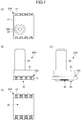
- FIG. 1 (A) is a top plan view
- FIG. 1 (B) and FIG. 1 (C) are side views
- FIG. 1 (D) is a bottom plan view of a pressure sensor device according to the present embodiment.
- a cover 20A is mounted on the upper surface of a board 10A
- a lid 30 is mounted on the lower surface of the board 10A.
- the board 10A is shaped like a plate having a rectangular shape in plan view.
- Multiple terminals 12 are arranged on two opposite sides of the board 10A.
- the cover 20A is a resin molded product and includes a box-shaped part 21 and a tubular part 25.
- the tubular part 25 has a columnar outer shape and is a tubular structure having a tubular-part upper-end opening 26t at an end.
- the lid 30 is shaped like a plate, and a lid opening 32 is formed in a side wall of the lid 30 as a second pressure inlet.
- FIG. 2 (A) is a top plan view and FIG. 2 (B) is a bottom plan view of the board of the pressure sensor device of the present embodiment.
- the board 10A is formed of, for example, a glass epoxy resin and includes a substrate 11 which serves as a body of a plate-shaped structure and on which the terminals 12 are formed as external connection terminals.
- the terminals 12 are formed along three surfaces, an upper surface, a side surface, and a lower surface, of the substrate 11.
- Wires 13 including lands are formed on the upper surface of the substrate 11 and are connected to the terminals 12.
- a through hole 14 is formed in the substrate 11.
- a pressure sensor element 15 is mounted on the upper surface of the substrate 11 so as to close the through hole 14.
- a control chip 16 is mounted on the upper surface of the substrate 11 at a position adjacent to the pressure sensor element 15. Bonding wires 17 connect the pressure sensor element 15 to the control chip 16, connect the pressure sensor element 15 to the land of the wire 13, and connect the control chip 16 to the lands of the wires 13.
- a metal layer 31e is formed on the lower surface of the substrate 11 around the through hole 14. The structure around the lid is described later.
- the board 10A is configured as described above.
- the pressure sensor element 15 is an element in which a diaphragm for detecting a pressure is formed.
- the pressure sensor element 15 is a semiconductor strain gauge element that detects strain of the diaphragm as a change in resistance, a capacitance element that detects displacement of the diaphragm as a change in capacitance, or an element that detects a measurement target pressure using any other detection technique.
- the pressure sensor element 15 is mounted on the upper surface of the board 10A with an adhesive such as a silicon resin such that the through hole of the board 10A communicates with one side of the diaphragm and the through hole 14 is closed.
- FIG. 3 (A) is a top perspective view and FIG. 3 (B) is a bottom perspective view of a cover of the pressure sensor device according to the present embodiment.
- the cover 20A includes the box-shaped part 21 and the tubular part 25.
- a first recess 22, a second recess 23, and a communicating part 24 through which the first recess 22 communicates with the second recess 23 are formed.
- a hollow structure (first hollow part) is formed by the surface of the board 10A and the inner surfaces of the first recess 22, the second recess 23, and the communicating part 24 of the cover 20A.
- the pressure sensor element 15 and the control chip 16 on the board 10A are housed in a space of the first hollow part corresponding to the first recess 22.
- the tubular part 25 is provided on a portion of the box-shaped part 21 above the second recess 23.
- An opening structure starting from the tubular-part upper-end opening 26t of the tubular part 25 passes through the tubular part 25 and the box-shaped part 21 and reaches the second recess 23.
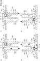
- FIG. 4 illustrate cross-sectional views of the pressure sensor device of the present embodiment.
- FIG. 4 (A) corresponds to a cross section taken along line XA-XB in FIG. 2 (A)
- FIG. 4 (B) corresponds to a cross section taken along line YA-YB in FIG. 2 (A) .
- the opening structure starting from the tubular-part upper-end opening 26t of the tubular part 25 reaches the second recess 23 through a tubular-part opening 26 inside of the tubular part 25 and a box-shaped-part through hole 21a.
- the second recess 23 communicates with the first recess 22 via the communicating part 24.
- a first channel for guiding a first fluid to the upper surface of the diaphragm structure of the pressure sensor element 15 extends from the tubular-part upper-end opening 26t of the tubular part 25, passes through the tubular-part opening 26, the box-shaped-part through hole 21a, the second recess 23, and the communicating part 24, and reaches the first recess 22.
- This fluid flow is indicated by black arrows.
- the first fluid is, for example, a pressure measurement target fluid.
- an arrow with a "+" symbol indicates a flow from a direction perpendicular to the page surface.
- a plate-shaped lid 30 is disposed at a predetermined distance from the lower surface of the board 10A to cover the through hole 14.
- the lid 30 is separated from the board 10A by a side wall 31.
- a hollow structure (second hollow part) is formed by the lower surface of the board 10A and the inner surfaces of the lid 30 and the side wall 31. A part of the side wall is removed to form a lid opening 32.
- the opening structure starting from the lid opening 32 communicates with the through hole 14 via the second hollow part and forms a second channel that guides a second fluid to the lower surface of the diaphragm structure of the pressure sensor element 15.
- This fluid flow is indicated by white arrows.
- the second fluid is, for example, a pressure measurement comparison target fluid such as air.
- an arrow with a "+" symbol indicates a flow from a direction perpendicular to the page surface.
- the board 10A has a rectangular shape in plan view.
- the terminals 12 are formed along two opposite sides of the rectangular board 10A, and the lid opening 32 is open toward a side different from the two opposite sides.
- the above configuration can suppress the flux of solder, which is generated near the terminals 12 that are fixed with solder when the pressure sensor device is mounted on the motherboard as described below, from entering the lid opening 32.
- the first fluid is guided to the upper surface of the pressure sensor element 15 and the second fluid is guided to the lower surface of the pressure sensor element 15.
- the strain or displacement of the diaphragm changes depending on the pressure of the first fluid and the pressure of the second fluid.
- the thickness of the board 10A is about 0.1 mm to 1 mm
- the board 10A is shaped like a rectangle each side of which has a length of about 2 mm to 20 mm in plan view.
- the box-shaped part 21 of the cover 20A has a height of about 1 mm and has such a size that the box-shaped part 21 does not cover the terminals when the cover 20A is mounted on the board 10A.
- the tubular part 25 has a diameter of about 0.5 mm, which corresponds to a fraction to one half of each side of the rectangular shape of the board 10A in plan view.
- the lid 30 is shaped like a plate with a thickness of about 0.1 mm to 1 mm.
- FIG. 5 (A) is a cross-sectional view of the lid of the pressure sensor device according to the present embodiment.
- a side wall 31 is formed to separate the lid 30 from the substrate 11 of the board 10A by a predetermined distance.
- the side wall 31 is formed by stacking a metal layer 31e of, for example, Cu, Ni, or Au; a resist layer 31d; a bonding sheet 31c, a resist layer 31b, and a metal layer 31a of, for example, copper.
- Each layer has a thickness of 0.1 ⁇ m to 200 ⁇ m, and the side wall 31 has a total thickness of about 10 ⁇ m to 500 ⁇ m.
- a distance "a" between the board 10A (substrate 11) and the lid 30 corresponds to this thickness.
- FIG. 5 (B) is a drawing illustrating a configuration of the lid.
- a method of forming the lid is described with reference to FIG. 5 (B) .
- the metal layer 31e is formed by patterning on the lower surface of the board 10A (substrate 11), and the resist layer 31d is formed by patterning on the metal layer 31e.
- the metal layer 31a and the resist layer 31b are formed by patterning on the surface of the lid 30 to be mounted on the board 10A.
- the resist layer 31b and the resist layer 31d are bonded to the upper surface and the lower surface of the bonding sheet 31c. As a result, the side wall 31 is formed.
- the lid opening 32 is formed in the side wall 31 of the lid 30.
- the lid opening 32 can be formed in the side wall 31 by forming the metal layer 31e, the resist layer 31d, the bonding sheet 31c, the resist layer 31b, and the metal layer 31a except in a region corresponding to the lid opening 32.
- FIG. 2 (B) illustrates a state where the metal layer 31e is formed on the lower surface of the board 10A around the through hole 14. This corresponds to the configuration where the metal layer 31e is formed around the through hole 14 except in a portion that becomes the lid opening 32.
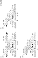
- FIG. 6 (A) and FIG. 6 (B) are cross-sectional views of an example where the pressure sensor device of the present embodiment is mounted on a motherboard, and correspond to the cross sections illustrated in FIG. 4 (A) and FIG. 4 (B) .
- the pressure sensor device is mounted on a motherboard 100 such that the tubular part 25 faces upward with respect to the motherboard 100.
- the motherboard 100 is a glass epoxy resin board such as FR-4. Terminals and wiring patterns (not shown) are formed on the surface of the motherboard 100.
- An opening 100A is formed in the motherboard 100.
- the pressure sensor device is mounted on the motherboard 100 such that the lid 30 of the pressure sensor device of the present embodiment is placed in the opening 100A, and the terminals 12 of the pressure sensor device are connected and fixed to the terminals (not shown) of the motherboard 100 by soldering. In this case, the lower and side surfaces of the terminals 12 are connected with solder.
- FIG. 7 (A) and FIG. 7(B) are cross-sectional views of another example where the pressure sensor device of the present embodiment is mounted on a motherboard, and correspond to cross sections obtained by inverting FIG. 4 (A) and FIG. 4 (B) .
- the pressure sensor device is mounted on the motherboard 100 such that the tubular part 25 faces downward with respect to the motherboard 100.
- the pressure sensor device is mounted on the motherboard 100 such that the cover 20A of the pressure sensor device of the present embodiment is placed in the opening 100A of the motherboard 100, and the terminals 12 of the pressure sensor device are connected and fixed to the terminals (not shown) of the motherboard 100 by soldering.
- the upper surfaces (surfaces closer to the cover 20A) and the side surfaces of the terminals 12 are connected with solder.
- both of the mounting method illustrated in FIG. 6 (A) and FIG. 6 (B) and the mounting method illustrated in FIG. 7 (A) and FIG. 7 (B) can be used without changing the configuration of the pressure sensor device.
- the board 10A has a rectangular shape in plan view, and the terminals 12 are formed along two opposite sides of the rectangular board 10A.
- the lid opening 32 is open toward a side different from the two opposite sides.
- the plate-shaped lid 30 is mounted on the lower surface of the board 10A to cover the through hole 14 and is separated at a predetermined distance from the board 10A. Because the through hole 14 is hidden from the outside, this configuration makes it possible to suppress the entry of dust such as flux through the through hole 14 into the pressure sensor element 15.
- the pressure sensor device of the present embodiment is implemented without using a lead frame, and the occupied area of the pressure sensor device mounted on a motherboard corresponds to the area of the board 10A.
- the present embodiment makes it possible to miniaturize a pressure sensor device. Because the pressure sensor device of the present embodiment is implemented by using inexpensive injection molded parts instead of using high-cost insert molding, the present embodiment can reduce costs.
- the pressure sensor element 15 is not disposed immediately below the tubular-part upper-end opening 26t.
- the second recess 23 functions as a dust trap.
- a structure that functions as a dust trap can be easily implemented by providing the second recess 23 and a channel communicating with the second recess 23 in the cover.
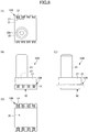
- FIG. 8 (A) is a top plan view
- FIG. 8 (B) and FIG. 8 (C) are side views
- FIG. 8 (D) is a bottom plan view of a pressure sensor device according to the present embodiment.
- a cover 20B is mounted on the upper surface of a board 10B
- a lid 30 is mounted on the lower surface of the board 10B.
- the board 10B is shaped like a rectangular plate in plan view. Multiple terminals 12 are arranged along two opposite sides of the board 10B.
- the cover 20B is a resin molded product and includes a box-shaped part 21 and a tubular part 25. At an upper corner (upper-end corner) of the box-shaped part 21, a box-shaped-part opening(s) 27 is formed as a first pressure inlet.
- the tubular part 25 is a tubular structure having a columnar outer shape, and a tubular-part upper-end opening 26t is provided at an end of the tubular structure as a second pressure inlet.
- FIG. 9 (A) is a top plan view and FIG. 9 (B) is a bottom plan view of the board of the pressure sensor device according to the present embodiment.
- a through hole 14 and a second through hole 18 are formed in a substrate 11 of the board 10B.
- a metal layer 31e is formed around the through hole 14 and the second through hole 18.
- the board 10B has substantially the same configuration as the board 10A of the first embodiment.
- the through hole 14 and the second through hole 18 are located on a dashed-dotted line ZA-ZB in the drawing.
- one or both of the through hole 14 and the second through hole 18 may be located off the dashed-dotted line ZA-ZB.
- FIG. 10 (A) is a top perspective view and FIG. 10 (B) is a bottom perspective view of the cover of the pressure sensor device according to the present embodiment.
- the cover 20B includes the box-shaped part 21 and the tubular part 25.
- a first recess 22 and a second recess 23 are formed in the surface of the box-shaped part 21 to be bonded to the board 10B.
- a hollow structure first hollow part
- a hollow structure is formed by the surface of the board 10B and the inner surface of the first recess 22 of the cover 20B.
- a hollow structure is formed by the surface of the board 10B and the inner surface of the second recess 23 of the cover 20B.
- the pressure sensor element 15 and the control chip 16 on the board 10B are housed in the space in the first hollow part.
- the second through hole 18 is located immediately below the second hollow part and communicates with the second hollow part.
- the tubular part 25 is provided on a portion of the box-shaped part 21 above the second recess 23.
- the opening structure starting from the tubular-part upper-end opening 26t of the tubular part 25 passes through the tubular part 25 and the box-shaped part 21 and reaches the second recess 23.
- the box-shaped-part opening 27 leading to the first recess 22 is formed in an upper corner of the box-shaped part 21.
- the box-shaped-part opening 27 may be formed in the upper surface or a side surface of the box-shaped part 21. Further, the box-shaped-part opening 27 may be formed in both of the upper surface and the side surface, and may be formed in the upper corner of the box-shaped part 21 as described above.
- FIG. 11 is a cross-sectional view of the pressure sensor device according to the present embodiment and corresponds to a cross section taken along line ZA-ZB in FIG. 9 (A) .
- the box-shaped-part opening 27 formed in the corner of the box-shaped part 21 of the cover 20B leads to the first recess 22 and constitutes a first channel that guides a first fluid to the upper surface of the diaphragm structure of the pressure sensor element 15. This fluid flow is indicated by a white arrow.
- the first fluid is, for example, a comparison target fluid for pressure measurement.
- a plate-shaped lid 30 is disposed at a predetermined distance from the lower surface of the board 10A to cover the through hole 14.
- the lid 30 is separated from the board 10A by a side wall 31, and a hollow structure (third hollow part) is formed by the lower surface of the board 10A and the inner surfaces of the lid 30 and the side wall 31.
- the side wall 31 is substantially the same as that in the first embodiment except that the lid opening is not formed.
- the opening structure starting from the tubular-part upper-end opening 26t of the tubular part 25 reaches the second recess 23 through the tubular-part opening 26 inside of the tubular part 25 and a box-shaped-part through hole 21a.
- the second recess 23 communicates via the second through hole 18 with the third hollow part formed by the lower surface of the board 10A and the inner surfaces of the lid 30 and the side wall 31.
- the third hollow part communicates via the through hole 14 with the lower surface of the diaphragm structure of the pressure sensor element 15.
- the opening structure starting from the tubular-part upper-end opening 26t communicates with the tubular-part opening 26, the box-shaped-part through hole 21a, the second hollow part, the second through hole 18, the third hollow part, and the through hole 14 and forms the second channel that guides the second fluid to the lower surface of the diaphragm structure of the pressure sensor element 15.
- This fluid flow is indicated by black arrows.
- the second fluid is, for example, a pressure measurement target fluid.
- the board 10A has a rectangular shape in plan view.
- the terminals 12 are formed along two opposite sides of the rectangular board 10A.
- the box-shaped-part opening(s) 27 is open on the two opposite sides where the terminals are formed.
- a configuration where the box-shaped-part opening 27 is open toward a side different from the opposite two sides where the terminals are formed is preferable because this configuration can suppress the flux of solder, which is generated near the terminals 12 that are soldered when the pressure sensor device is mounted, from entering the box-shaped-part opening 27.
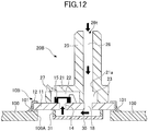
- FIG. 12 is a cross-sectional view of an example where the pressure sensor device according to the present embodiment is mounted on a motherboard.
- the pressure sensor device is mounted on a motherboard 100 such that the tubular part 25 faces upward with respect to the motherboard 100.
- the motherboard 100 is a glass epoxy resin board such as FR-4. Terminals and wiring patterns (not shown) are formed on the surface of the motherboard 100.
- An opening 100A is formed in the motherboard 100.
- the pressure sensor device is mounted on the motherboard 100 such that the lid 30 of the pressure sensor device of the present embodiment is placed in the opening 100A, and the terminals 12 of the pressure sensor device are connected and fixed to the terminals (not shown) of the motherboard 100 by soldering. In this case, the lower and side surfaces of the terminals 12 are connected with solder.
- FIG. 13 is a cross-sectional view of another example where the pressure sensor device according to the present embodiment is mounted on the motherboard, and corresponds to a cross section obtained by inverting FIG. 11 .
- the pressure sensor device is mounted on the motherboard 100 such that the tubular part 25 faces downward with respect to the motherboard 100.
- the pressure sensor device is mounted on the motherboard 100 such that the cover 20B of the pressure sensor device of the present embodiment is placed in the opening 100A of the motherboard 100, and the terminals 12 of the pressure sensor device are connected and fixed to the terminals (not shown) of the motherboard 100 by soldering.
- the upper surfaces (surfaces closer to the cover 20A) and the side surfaces of the terminals 12 are connected with solder.
- both of the mounting method illustrated in FIG. 12 and the mounting method illustrated in FIG. 13 can be used without changing the configuration of the pressure sensor device.
- the plate-shaped lid 30 is mounted on the lower surface of the board 10B to cover the through hole 14 and is separated at a predetermined distance from the board 10B. Because the through hole 14 is hidden from the outside, this configuration makes it possible to suppress the entry of dust such as flux through the through hole 14 into the pressure sensor element 15.
- the pressure sensor device of the present embodiment is implemented without using a lead frame, and the occupied area of the pressure sensor device mounted on a motherboard corresponds to the area of the board 10B.
- the present embodiment makes it possible to miniaturize a pressure sensor device. Because the pressure sensor device is implemented by using inexpensive injection molded parts instead of using high-cost insert molding, the present embodiment can reduce costs.
- the pressure sensor element 15 is not disposed immediately below the tubular-part upper-end opening 26t.
- the dust is trapped in the second recess 23 located immediately below the tubular-part upper-end opening 26t or the third hollow part and cannot readily reach the pressure sensor element 15.
- the second recess 23 and the third hollow part function as dust traps.
- a structure that functions as a dust trap can be easily implemented by providing the second recess 23 and a channel communicating with the second recess 23 in the cover.
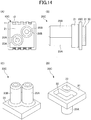
- FIG. 14 (A) is a top plan view and FIG. 14 (B) is a side view of a pressure sensor device according to a first variation; and FIG. 14 (C) is a top perspective view and FIG. 14 (D) is a bottom perspective view of a cover.
- a cover 20C is mounted on the upper surface of a board 10C, and a lid 30 is mounted on the lower surface of the board 10C via a side wall 31.
- the cover 20C includes a box-shaped part 21, a first tubular part 25A, and a second tubular part 25B.
- the first tubular part 25A is a tubular structure having a columnar outer shape, and a tubular-part upper-end opening 26A is provided at an end of the tubular structure as a second pressure inlet.
- the second tubular part 25B is a tubular structure having a columnar outer shape, and a tubular-part upper-end opening 26B is provided at an end of the tubular structure as a first pressure inlet.
- the first tubular part 25A is provided on a portion of the box-shaped part 21 above the second recess 23 and similarly to the second embodiment, the tubular-part upper-end opening 26A communicates with the lower surface of the diaphragm structure of the pressure sensor element 15 through the second hollow part and the third hollow part.
- the second tubular part 25B is provided on a portion of the box-shaped part 21 above the first recess 22.
- the tubular-part upper-end opening 26B communicates with the upper surface of the diaphragm structure of the pressure sensor element 15 in the first hollow part.
- fluids other than air are introduced from the first tubular part 25A and the second tubular part 25B to the pressure sensor element 15, and the pressure difference between the two fluids can be obtained as information.
- FIG. 15 (A) is a cross-sectional view of a pressure sensor device according to an example of a second variation.
- the pressure sensor device of the first variation is mounted on the motherboard 100.
- the pressure sensor device is mounted such that the first tubular part 25A and the second tubular part 25B face downward with respect to the motherboard 100.
- a pressure measurement target fluid black arrow
- a pressure measurement comparison target fluid white arrow
- FIG. 15 (B) is a cross-sectional view of a pressure sensor device according to another example of the second variation.
- the pressure sensor device of the first variation is mounted on the motherboard 100.
- the pressure sensor device is mounted such that the first tubular part 25A and the second tubular part 25B face upward with respect to the motherboard 100.
- a pressure measurement target fluid black arrow
- a pressure measurement comparison target fluid white arrow
- FIG. 15 (C) is a cross-sectional view of a pressure sensor device according to another example of the second variation.
- the pressure sensor device of the first variation is mounted on the motherboard 100.
- the pressure sensor device is mounted such that the first tubular part 25A and the second tubular part 25B face downward with respect to the motherboard 100.
- a pressure measurement comparison target fluid (white arrow) is introduced into the first tubular part 25A
- a pressure measurement target fluid (black arrow) is introduced into the second tubular part 25B.
- FIG. 15 (D) is a cross-sectional view of a pressure sensor device according to another example of the second variation.
- the pressure sensor device of the first variation is mounted on the motherboard 100.
- the pressure sensor device is mounted such that the first tubular part 25A and the second tubular part 25B face upward with respect to the motherboard 100.
- a pressure measurement comparison target fluid (white arrow) is introduced into the first tubular part 25A
- a pressure measurement target fluid (black arrow) is introduced into the second tubular part 25B.
- FIG. 16 (A) is a cross-sectional view of a configuration where a pressure sensor device according to an example of a third variation is mounted on the motherboard 100.
- a first tubular part 25C whose end is bent outward is formed.
- a second tubular part 25D whose end is bent outward is formed.
- the pressure sensor device is mounted such that the first tubular part 25C and the second tubular part 25D face upward with respect to the motherboard 100.
- Either a pressure measurement target fluid (black arrow) or a pressure measurement comparison target fluid (white arrow) is introduced into each of the first tubular part 25C and the second tubular part 25D.
- the first hollow part formed in the cover 20D is implemented by two recesses that communicate with each other.
- the first hollow part may have any other configuration.
- FIG. 16 (B) is a cross-sectional view of a configuration where a pressure sensor device according to an example the fourth variation is mounted on the motherboard 100. This corresponds to a configuration obtained by removing the first tubular part 25C of the pressure sensor device of the third variation.
- An opening 28 is formed in the upper surface of the box-shaped part 21 of a cover 20E to form a channel communicating with the lower surface of the diaphragm structure of the pressure sensor element 15.
- a pressure measurement target fluid black arrow
- a pressure measurement comparison target fluid (white arrow) is introduced into the opening 28 in the upper surface of the box-shaped part 21.
- FIG. 16 (C) is a cross-sectional view of a configuration where a pressure sensor device according to a fifth variation is mounted on the motherboard 100.
- This configuration is obtained by replacing the tubular part 25 in the pressure sensor device of the first embodiment with a tubular part 25E whose end is bent outward.
- the pressure sensor device is mounted such that the tubular part 25E faces upward with respect to the motherboard 100.
- a pressure measurement target fluid black arrow
- a pressure measurement comparison target fluid (white arrow) is introduced into the lid opening of the lid 30.
- the plate-shaped lid 30 is mounted on the lower surface of the board to cover the through hole 14 and is separated by a predetermined distance from the board. Because the through hole 14 is hidden from the outside, this configuration makes it possible to suppress the entry of dust such as flux through the through hole 14 into the pressure sensor element 15.
- the pressure sensor devices of the above-described variations are implemented without using a lead frame, and the occupied area of each of the pressure sensor devices mounted on a motherboard corresponds to the area of the board.
- the configurations of the variations make it possible to miniaturize a pressure sensor device. Because the pressure sensor devices of the variations are implemented by using inexpensive injection molded parts instead of using high-cost insert molding, the configurations of the variations can reduce costs.
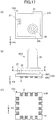
- FIG. 17 (A) is a top plan view
- FIG. 17 (B) is a side view
- FIG. 17 (C) is a bottom plan view of a pressure sensor device according to the present embodiment.
- a cover 20G is mounted on the upper surface of a board 10G.
- the board 10G is shaped like a plate having a rectangular shape in plan view.
- multiple terminals 12 are arranged on each of the four sides of the board 10G.
- the cover 20G is a resin molded product and includes a box-shaped part 21 and a tubular part 25.
- a box-shaped-part opening(s) 27 is formed as a first pressure inlet.
- the tubular part 25 is a tubular structure having a columnar outer shape, and a tubular-part upper-end opening 26t is provided at an end of the tubular structure as a second pressure inlet.
- the board 10G includes a first board 200 on which the multiple terminals 12 are provided and a second board 300 stacked on the first board 200 and having a through hole described later.
- the first board 200 and the second board 300 are bonded together using a bonding sheet described later.
- the first board 200 functions as a lid.
- no metal layer other than the terminals 12 is formed on the lower surface of the first board 200, and a region other than the terminals 12 is covered with a resist layer.
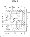
- FIG. 18 is a cross-sectional view of the pressure sensor device according to the present embodiment, and corresponds to a cross section taken along A-A' in FIG. 17 (B) .
- a first through hole 14 and a second through hole 18 are formed in the second board 300.
- the pressure sensor element 15 and the control chip 16 are mounted on the second board 300.
- the pressure sensor element 15 is mounted on the upper surface of the second board 300 using an adhesive such as a silicone resin to close the first through hole 14.
- Land openings 301 are formed in portions of the second board 300 near the pressure sensor element 15 and the control chip 16 to expose lands 13a of wires 13 provided on the first board 200. Bonding wires 17 connect the pressure sensor element 15 to the control chip 16, connect the pressure sensor element 15 to the lands 13a of the wires 13, and connect the control chip 16 to the lands 13a of the wires 13.
- FIG. 19 is cross-sectional views of the pressure sensor device according to the present embodiment.
- FIG. 19 (A) corresponds to a cross section taken along line B-B' in FIG. 18 .
- FIG. 19 (B) corresponds to a cross section taken along line C-C' in FIG. 18 .
- the first recess 22 and the second recess 23 are formed in a surface of the box-shaped part 21 to be bonded to the board 10G.
- a hollow structure is formed by the surface of the board 10G and the inner surface of the first recess 22 of the cover 20G. Also, a hollow structure (second hollow part) is formed by the surface of the board 10G and the inner surface of the second recess 23 of the cover 20G.
- the pressure sensor element 15 and the control chip 16 on the board 10G are housed in the space in the first hollow part.
- the second through hole 18 is located immediately below the second hollow part and communicates with the second hollow part.
- the tubular part 25 is provided on the box-shaped part 21. The opening structure starting from the tubular-part upper-end opening 26t of the tubular part 25 passes through the tubular part 25 and the box-shaped part 21 and reaches the second recess 23.
- a box-shaped-part opening 27 leads to the first recess 22 and constitutes a first channel that guides a first fluid to the upper surface of the diaphragm structure of the pressure sensor element 15.
- the fluid flow is indicated by white arrows in FIG. 19 (B) .
- the first fluid is, for example, a pressure measurement comparison target fluid.
- a recess 302 is formed in the second board 300 constituting the board 10G to face the first board 200.
- the recess 302 communicates with the first through hole 14 and the second through hole 18.
- a hollow structure (third hollow part) is formed by the surface of the first board 200 and the inner surface of the recess 302 of the second board 300.
- a recess may also be formed in a region of the surface of the first board 200 facing the recess 302.
- the opening structure starting from the tubular-part upper-end opening 26t reaches the second recess 23 through the tubular-part opening 26 inside of the tubular part 25 and the box-shaped-part through hole 21a.
- the second recess 23 communicates via the second through hole 18 with the third hollow part.
- the third hollow part communicates via the through hole 14 with the lower surface of the diaphragm structure of the pressure sensor element 15.
- the opening structure starting from the tubular-part upper-end opening 26t communicates with the tubular-part opening 26, the box-shaped-part through hole 21a, the second hollow part, the second through hole 18, the third hollow part, and the through hole 14 and forms the second channel that guides the second fluid to the lower surface of the diaphragm structure of the pressure sensor element 15.
- This fluid flow is indicated by black arrows in FIG. 19 (A) .
- the second fluid is, for example, a pressure measurement target fluid.
- FIG. 20 (A) is a top plan view of the first board 200.
- FIG. 20 (B) is a cross-sectional view of the first board 200 and corresponds to a cross section taken along line D-D' in FIG. 20 (A) .
- the first board 200 includes a substrate 210 as a base.
- the substrate 210 is formed of, for example, a glass epoxy resin and serves as a body of a plate-shaped structure.
- a metal layer of, for example, Cu, Ni, or Au and a resist layer are stacked on the upper and lower surfaces of the substrate 210.
- the terminals 12, the wires 13, and the lands 13a are formed by the metal layer.
- An Au plating layer is preferably formed on the surface of each land 13a.
- a resist layer 211 is formed on the upper surface of the substrate 210 to cover the metal layer. Openings 201 for exposing the lands 13a are formed in the resist layer 211. The openings 201 are formed at positions corresponding to the land openings 301 formed in the second board 300 with the same shapes and sizes as the land openings 301.
- the recess 202 has the same shape and size as the recess 302. Although the recess 202 is not essential, when the recess 202 is formed, the recess 202 (first recess) and the recess 302 (second recess) face each other and form the third hollow part that constitutes the second channel.
- a frame 203 comprised of a metal layer (e.g., copper foil) is formed around the recess 202.
- the upper surface of the frame 203 is covered by the resist layer 211.
- a resist layer 212 is formed in a region of the lower surface of the substrate 210 other than the terminals 12.
- An Au plating layer is preferably formed on the surface of each terminal 12.
- FIG. 21 (A) is a top plan view of the second board 300
- FIG. 21 (B) is a bottom plan view of the second board 300
- FIG. 22 is a cross-sectional view of the second board 300 and corresponds to a cross section taken along line E-E' in FIG. 21 (A) .
- the second board 300 includes a substrate 310 as a base.
- the substrate 310 is formed of, for example, a glass epoxy resin and serves as a body of a plate-shaped structure.
- a first through hole 14, a second through hole 18, and land openings 301 are formed in the second board 300.
- a resist layer 311 is formed on the lower surface of the substrate 310 to cover a metal layer of, for example, Cu.
- the recess 302 is formed by removing a region including the first through hole 14 and the second through hole 18.
- a frame 303 comprised of a metal layer (e.g., copper foil) is formed.
- a frame 304 comprised of a metal layer (e.g., copper foil) is formed along the outer periphery of the substrate 310.
- the frame 303 and the frame 304 are covered by the resist layer 311. Also, regions of the resist layer 311 corresponding to the land openings 301 are removed.
- FIG. 23 is a drawing illustrating a method of joining the first board 200 and the second board 300.
- FIG. 23 (A) illustrates a state before the boards are joined and
- FIG. 23 (B) illustrates a state after the boards are joined.
- the second board 300 is bonded to the first board 200 via a bonding sheet 400.
- the bonding sheet 400 includes openings formed in regions corresponding to the land openings 301 and the recess 302.
- the board 10G is formed by bonding the first board 200 to the second board 300 via the bonding sheet 400 such that the openings 201 and the recess 202 of the first board 200 are aligned with the land openings 301 and the recess 302 of the second board 300.
- the present embodiment makes it possible to easily form the third hollow part constituting the second channel between the first board 200 and the second board 300.
- the second channel is formed by the recess 202 formed in the first board 200 and the recess 302 formed in the second board 300.
- the second channel may be formed by one of the recess 202 and the recess 302.
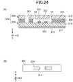
- FIG. 24 is a drawing illustrating a board according to a first variation of the third embodiment.
- FIG. 24 (A) is a cross-sectional view.
- FIG. 24 (B) is a plan view of the recess 202.
- protrusions 220 are formed in the recess 202 of the first board 200.
- the protrusions 220 are formed by patterning the metal layer and the resist layer formed on the upper surface of the substrate 210.
- two rectangular protrusions 220 are disposed in the recess 202.
- the shape and number of the protrusions 220 are not limited to this example.
- the substrate 210 and the substrate 310 are prevented from contacting each other in the third hollow part, and the second channel can be maintained.
- protrusions may also be formed in the recess 302 of the second board 300. Also, protrusions may be formed only in the recess 302 of the second board 300.
- FIG. 25 (A) is a top plan view
- FIG. 25 (B) is a side view
- FIG. 25 (C) is a bottom plan view of a pressure sensor device according to a second variation of the third embodiment
- FIG. 26 is a cross-sectional view of the pressure sensor device according to the second variation of the third embodiment, and corresponds to a cross section taken along line F-F' in FIG. 25 (B) .
- a cover 20H is mounted on the upper surface of the board 10G.
- the cover 20H includes a box-shaped part 21, a first tubular part 25A, and a second tubular part 25B.
- the board 10G has the same configuration as the board 10G of the third embodiment.
- the first tubular part 25A is a tubular structure having a columnar outer shape, and a tubular-part upper-end opening 26A is provided at an end of the tubular structure as a second pressure inlet.
- the second tubular part 25B is a tubular structure having a columnar outer shape, and a tubular-part upper-end opening 26B is provided at an end of the tubular structure as a first pressure inlet.
- the first tubular part 25A is provided on a portion of the box-shaped part 21 above the second recess 23.
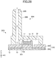
- FIGs. 27 and 28 are cross-sectional views of the pressure sensor device according to this variation.
- FIG. 27 corresponds to a cross section taken along G-G' in FIG. 26 .
- FIG. 28 corresponds to a cross section taken along line H-H' in FIG. 18 .
- the first recess 22 and the second recess 23 are formed in a surface of the box-shaped part 21 to be bonded to the board 10G.
- the tubular-part upper-end opening 26A communicates with the lower surface of the diaphragm structure of the pressure sensor element 15 via the second hollow part and the third hollow part and forms a second channel.
- the second tubular part 25B is provided on a portion of the box-shaped part 21 above the first recess 22. As illustrated in FIG. 28 , the tubular-part upper-end opening 26B communicates with the upper surface of the diaphragm structure of the pressure sensor element 15 in the first hollow part and forms a first channel.
- fluids other than air are introduced from the first tubular part 25A and the second tubular part 25B to the pressure sensor element 15, and the pressure difference between the two fluids can be obtained as information.
- the board 10G can be modified similarly to the third embodiment.
- the first tubular part 25A of this variation corresponds to a second tubular part recited in the claims
- the second tubular part 25B corresponds to a first tubular part recited in the claims.
- FIG. 29 (A) is a top plan view
- FIG. 29 (B) is a side view
- FIG. 29 (C) is a bottom plan view of a pressure sensor device according to a third variation of the third embodiment.
- FIG. 30 is a cross-sectional view of the pressure sensor device according to the third variation of the third embodiment and corresponds to a cross section taken along line I-I' in FIG. 29 (B) .
- a cover 20J is mounted on the upper surface of the board 10G.
- the cover 20J includes a box-shaped part 21 and a second tubular part 25B.
- the cover 20J of this variation is different from the cover 20H of the second variation in that the cover 20J does not include the first tubular part 25A.
- an opening 26C is formed in the upper surface of the box-shaped part 21 as a pressure inlet that communicates with the second recess 23.
- the board 10G has the same configuration as the board 10G according to the third embodiment.
- FIGs. 31 and 32 are cross-sectional views of the pressure sensor device according to this variation.
- FIG. 31 corresponds to a cross section taken along line J-J' in FIG. 30 .
- FIG. 32 corresponds to a cross section taken along line K-K' in FIG. 30 .
- the first recess 22 and the second recess 23 are formed in a surface of the box-shaped part 21 to be bonded to the board 10G.
- the opening 26C communicates with the lower surface of the diaphragm structure of the pressure sensor element 15 via the second hollow part and the third hollow part and forms a second channel.
- the tubular-part upper-end opening 26B communicates with the upper surface of the diaphragm structure of the pressure sensor element 15 in the first hollow part and forms a first channel.
- fluids other than air are guided to the pressure sensor element 15 from the opening 26C and the second tubular part 25B, and the pressure difference between the two fluids can be obtained as information.
- FIG. 33 (A) is a top plan view
- FIG. 33 (B) is a side view
- FIG. 33 (C) is a bottom plan view of a pressure sensor device according to a fourth variation of the third embodiment
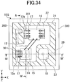
- FIG. 34 is a cross-sectional view of the pressure sensor device according to the fourth variation of the third embodiment, and corresponds to a cross section taken along line L-L' in FIG. 33 (B) .
- a cover 20K is mounted on the upper surface of the board 10G.
- the cover 20K includes a box-shaped part 21 and a second tubular part 25B.
- the cover 20K of this variation differs from the cover 20J of the third variation in the position where an opening is formed as a pressure inlet that communicates with the second recess 23.
- the opening 26C described in the third variation is not formed in the upper surface of the box-shaped part 21.
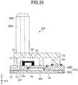
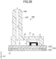
- FIGs. 35 and 36 are cross-sectional views of the pressure sensor device according to this variation.
- FIG. 35 corresponds to a cross section taken along line M-M' in FIG. 34 .
- FIG. 36 corresponds to a cross section taken along line N-N' in FIG. 30 .
- the first recess 22 and the second recess 23 are formed in a surface of the box-shaped part 21 to be bonded to the board 10G.
- an opening 29 is formed in a side surface of the box-shaped part 21 as a pressure inlet that communicates with the second recess 23. Also, in this variation, the opening 29 is located between the box-shaped part 21 and the second board 300 and is shaped like a groove. The opening 29 communicates with the lower surface of the diaphragm structure of the pressure sensor element 15 via the second hollow part and the third hollow part and forms a second channel. Also, as illustrated in FIG. 36 , the tubular-part upper-end opening 26B communicates with the upper surface of the diaphragm structure of the pressure sensor element 15 in the first hollow part and forms a first channel.
- fluids other than air are guided to the pressure sensor element 15 from the opening 29 and the second tubular part 25B, and the pressure difference between the two fluids can be obtained as information.
- the through hole of the substrate does not necessarily have a circular shape, and may have a different shape such as a square shape.
Landscapes
- Physics & Mathematics (AREA)
- General Physics & Mathematics (AREA)
- Chemical & Material Sciences (AREA)
- Analytical Chemistry (AREA)
- Measuring Fluid Pressure (AREA)
Abstract
Description
- The present invention relates to a pressure sensor device including a semiconductor pressure sensor element.
- A pressure sensor device includes a semiconductor pressure sensor element, and has a packaged configuration including a pressure inlet for introducing a fluid as a measurement target and an air inlet for introducing air as a comparison target. The semiconductor pressure sensor element is a chip that has a structure where a piezoelectric element is provided on the surface of a diaphragm deformable by the pressures of the introduced fluid and the introduced air, and detects the pressure of the fluid relative to the atmospheric pressure.
- As described above, when the atmospheric pressure is used as the comparison target pressure, the pressure sensor device is configured such that air is introduced into the air inlet; and when a pressure other than the atmospheric pressure is used as the comparison target, the pressure sensor device is configured such a fluid with the comparison target pressure is introduced into the air inlet.
- In the pressure sensor device, terminals of the piezoelectric element in the semiconductor pressure sensor element are connected to external connection terminals of the pressure sensor device. The external connection terminals of the pressure sensor device are fixed to terminals provided on a mounting surface of a motherboard by soldering. Thus, when the pressure sensor device is used, the pressure sensor device is mounted on the motherboard.
- For example,
Patent Documents 1 and 2 disclose pressure sensor devices including a semiconductor pressure sensor element. -
- [Patent Document 1] Japanese Unexamined Patent Application Publication No.
2012-233872 - [Patent Document 2] Japanese Unexamined Patent Application Publication No.
2012-052874 - The pressure sensor device disclosed in
Patent Document 1 is formed by insert molding using a lead frame and is configured such that leads extend outward from the package of the pressure sensor device. Because the leads extend outward, the occupied area of the pressure sensor device mounted on a motherboard becomes large, and it is difficult to reduce the size of the pressure sensor device. - In the pressure sensor device disclosed in Patent Document 2, a semiconductor pressure sensor element is disposed directly below a pressure inlet. For this reason, when dust such as flux enters the pressure inlet, the dust may directly adhere to and greatly affect the semiconductor pressure sensor element and may prevent the semiconductor pressure sensor element from operating correctly.
- One object of the present invention is to provide a pressure sensor device that can be miniaturized and is configured to suppress the entry of dust into a pressure inlet.
- To achieve the above object, a pressure sensor device of the present invention includes a first board including external connection terminals, a second board stacked on an upper surface of the first board and including a first through hole and a second through hole formed therein, a pressure sensor element including a diaphragm structure and mounted on an upper surface of the second board such that the first through hole is closed by the diaphragm structure, and a cover that is mounted on the upper surface of the second board to cover the pressure sensor element and in which a first channel for guiding a first fluid to an upper surface of the diaphragm structure is formed. A second channel is formed between the first board and the second board, and the second channel leads from the second through hole to the first through hole and guides a second fluid to a lower surface of the diaphragm structure.
- The present invention makes it possible to miniaturize a pressure sensor device and to suppress the entry of dust into a pressure inlet of the pressure sensor device.
-
-
FIG. 1 is a top plan view (A), a side view (B), a side view (C), and a bottom plan view (D) of a pressure sensor device according to a first embodiment; -
FIG. 2 is a top plan view (A) and a bottom plan view (B) of a board of the pressure sensor device according to the first embodiment; -
FIG. 3 is a top perspective view (A) and a bottom perspective view (B) of a cover of the pressure sensor device according to the first embodiment; -
FIG. 4 is cross-sectional views of the pressure sensor device according to the first embodiment; -
FIG. 5 is a cross-sectional view (A) of a lid of the pressure sensor device according to the first embodiment and a drawing (B) illustrating a configuration of the lid; -
FIG. 6 is cross-sectional views of an example of the pressure sensor device of the first embodiment mounted on a motherboard; -
FIG. 7 is cross-sectional views of another example of the pressure sensor device of the first embodiment mounted on a motherboard; -
FIG. 8 is a top plan view (A), a side view (B), a side view (C), and a bottom plan view (D) of a pressure sensor device according to a second embodiment; -
FIG. 9 is a top plan view (A) and a bottom plan view (B) of a board of the pressure sensor device according to the second embodiment; -
FIG. 10 is a top perspective view (A) and a bottom perspective view (B) of a cover of the pressure sensor device according to the second embodiment; -
FIG. 11 is a cross-sectional view of the pressure sensor device according to the second embodiment; -
FIG. 12 is a cross-sectional view of an example of the pressure sensor device of the second embodiment mounted on a motherboard; -
FIG. 13 is a cross-sectional view of another example of the pressure sensor device of the second embodiment mounted on a motherboard; -
FIG. 14 is a top plan view (A) and a side view (B) of a pressure sensor device and a top perspective view (C) and a bottom perspective view (D) of a cover according to a first variation; -
FIG. 15 is cross-sectional views of a pressure sensor device according to a second variation; -
FIG. 16 is cross-sectional views of pressure sensor devices according to third through fifth variations; -
FIG. 17 is a top plan view (A), a side view (B), and a bottom plan view (C) of a pressure sensor device according to a third embodiment; -
FIG. 18 is a cross-sectional view taken along line A-A' inFIG. 17 (B) ; -
FIG. 19 is a cross-sectional view (A) taken along line B-B' and a cross-sectional view (B) taken along line C-C' inFIG. 18 ; -
FIG. 20 is a top plan view (A) of a first board and a cross-sectional view (B) taken along line D-D' inFIG. 20 (A) ; -
FIG. 21 is a top plan view (A) and a bottom plan view (B) of a second board; -
FIG. 22 is a cross-sectional view taken along line E-E' inFIG. 21 (A) ; -
FIG. 23 is cross-sectional view (A) of the first board and the second board before being joined and a cross-sectional view (B) of the first board and the second board after being joined; -
FIG. 24 is a cross-sectional view (A) illustrating a board according to a first variation of the third embodiment and a plan view (B) of a recess of a first board; -
FIG. 25 is a top plan view (A), a side view (B), and a bottom plan view (C) of a pressure sensor device according to a second variation of the third embodiment; -
FIG. 26 is a cross-sectional view taken along line F-F' inFIG. 25 (B) ; -
FIG. 27 is a cross-sectional view taken along line G-G' inFIG. 26 ; -
FIG. 28 is a cross-sectional view taken along line H-H' inFIG. 26 ; -
FIG. 29 is a top plan view (A), a side view (B), and a bottom plan view (C) of a pressure sensor device according to a third variation of the third embodiment; -
FIG. 30 is a cross-sectional view taken along line I-I' inFIG. 29 (B) ; -
FIG. 31 is a cross-sectional view taken along line J-J' inFIG. 30 ; -
FIG. 32 is a cross-sectional view taken along line K-K' inFIG. 30 ; -
FIG. 33 is a top plan view (A), a side view (B), and a bottom plan view (C) of a pressure sensor device according to a fourth variation of the third embodiment; -
FIG. 34 is a cross-sectional view taken along line L-L' inFIG. 33 (B) ; -
FIG. 35 is a cross-sectional view taken along line M-M' inFIG. 34 ; and -
FIG. 36 is a cross-sectional view taken along line N-N' inFIG. 34 . - An embodiment of the present invention is described below with reference to the accompanying drawings.
FIG. 1 (A) is a top plan view,FIG. 1 (B) and FIG. 1 (C) are side views, andFIG. 1 (D) is a bottom plan view of a pressure sensor device according to the present embodiment. Acover 20A is mounted on the upper surface of aboard 10A, and alid 30 is mounted on the lower surface of theboard 10A. Theboard 10A is shaped like a plate having a rectangular shape in plan view.Multiple terminals 12 are arranged on two opposite sides of theboard 10A. - The
cover 20A is a resin molded product and includes a box-shapedpart 21 and atubular part 25. Thetubular part 25 has a columnar outer shape and is a tubular structure having a tubular-part upper-end opening 26t at an end. Thelid 30 is shaped like a plate, and alid opening 32 is formed in a side wall of thelid 30 as a second pressure inlet. -
FIG. 2 (A) is a top plan view andFIG. 2 (B) is a bottom plan view of the board of the pressure sensor device of the present embodiment. Theboard 10A is formed of, for example, a glass epoxy resin and includes asubstrate 11 which serves as a body of a plate-shaped structure and on which theterminals 12 are formed as external connection terminals. Theterminals 12 are formed along three surfaces, an upper surface, a side surface, and a lower surface, of thesubstrate 11.Wires 13 including lands are formed on the upper surface of thesubstrate 11 and are connected to theterminals 12. - A through
hole 14 is formed in thesubstrate 11. Apressure sensor element 15 is mounted on the upper surface of thesubstrate 11 so as to close the throughhole 14. Acontrol chip 16 is mounted on the upper surface of thesubstrate 11 at a position adjacent to thepressure sensor element 15.Bonding wires 17 connect thepressure sensor element 15 to thecontrol chip 16, connect thepressure sensor element 15 to the land of thewire 13, and connect thecontrol chip 16 to the lands of thewires 13. Ametal layer 31e is formed on the lower surface of thesubstrate 11 around the throughhole 14. The structure around the lid is described later. Theboard 10A is configured as described above. - The
pressure sensor element 15 is an element in which a diaphragm for detecting a pressure is formed. Thepressure sensor element 15 is a semiconductor strain gauge element that detects strain of the diaphragm as a change in resistance, a capacitance element that detects displacement of the diaphragm as a change in capacitance, or an element that detects a measurement target pressure using any other detection technique. Thepressure sensor element 15 is mounted on the upper surface of theboard 10A with an adhesive such as a silicon resin such that the through hole of theboard 10A communicates with one side of the diaphragm and the throughhole 14 is closed. -
FIG. 3 (A) is a top perspective view andFIG. 3 (B) is a bottom perspective view of a cover of the pressure sensor device according to the present embodiment. Thecover 20A includes the box-shapedpart 21 and thetubular part 25. In the surface of the box-shapedpart 21 to be bonded to theboard 10A, afirst recess 22, asecond recess 23, and a communicatingpart 24 through which thefirst recess 22 communicates with thesecond recess 23 are formed. When thecover 20A is mounted on theboard 10A, a hollow structure (first hollow part) is formed by the surface of theboard 10A and the inner surfaces of thefirst recess 22, thesecond recess 23, and the communicatingpart 24 of thecover 20A. Thepressure sensor element 15 and thecontrol chip 16 on theboard 10A are housed in a space of the first hollow part corresponding to thefirst recess 22. Thetubular part 25 is provided on a portion of the box-shapedpart 21 above thesecond recess 23. An opening structure starting from the tubular-part upper-end opening 26t of thetubular part 25 passes through thetubular part 25 and the box-shapedpart 21 and reaches thesecond recess 23. -
FIG. 4 illustrate cross-sectional views of the pressure sensor device of the present embodiment.FIG. 4 (A) corresponds to a cross section taken along line XA-XB inFIG. 2 (A) , andFIG. 4 (B) corresponds to a cross section taken along line YA-YB inFIG. 2 (A) . As described above, the opening structure starting from the tubular-part upper-end opening 26t of thetubular part 25 reaches thesecond recess 23 through a tubular-part opening 26 inside of thetubular part 25 and a box-shaped-part throughhole 21a. Thesecond recess 23 communicates with thefirst recess 22 via the communicatingpart 24. - Thus, a first channel for guiding a first fluid to the upper surface of the diaphragm structure of the
pressure sensor element 15 extends from the tubular-part upper-end opening 26t of thetubular part 25, passes through the tubular-part opening 26, the box-shaped-part throughhole 21a, thesecond recess 23, and the communicatingpart 24, and reaches thefirst recess 22. This fluid flow is indicated by black arrows. The first fluid is, for example, a pressure measurement target fluid. In the figures, an arrow with a "+" symbol indicates a flow from a direction perpendicular to the page surface. - A plate-shaped
lid 30 is disposed at a predetermined distance from the lower surface of theboard 10A to cover the throughhole 14. Thelid 30 is separated from theboard 10A by aside wall 31. A hollow structure (second hollow part) is formed by the lower surface of theboard 10A and the inner surfaces of thelid 30 and theside wall 31. A part of the side wall is removed to form alid opening 32. The opening structure starting from thelid opening 32 communicates with the throughhole 14 via the second hollow part and forms a second channel that guides a second fluid to the lower surface of the diaphragm structure of thepressure sensor element 15. This fluid flow is indicated by white arrows. The second fluid is, for example, a pressure measurement comparison target fluid such as air. In the figures, an arrow with a "+" symbol indicates a flow from a direction perpendicular to the page surface. - In the pressure sensor device of the present embodiment, the
board 10A has a rectangular shape in plan view. Theterminals 12 are formed along two opposite sides of therectangular board 10A, and thelid opening 32 is open toward a side different from the two opposite sides. Compared with a configuration where thelid opening 32 is open toward theterminals 12, the above configuration can suppress the flux of solder, which is generated near theterminals 12 that are fixed with solder when the pressure sensor device is mounted on the motherboard as described below, from entering thelid opening 32. - As described above, the first fluid is guided to the upper surface of the
pressure sensor element 15 and the second fluid is guided to the lower surface of thepressure sensor element 15. The strain or displacement of the diaphragm changes depending on the pressure of the first fluid and the pressure of the second fluid. By detecting the strain or displacement of the diaphragm as the amount of change in resistance or capacitance, it is possible to measure the pressure of the first fluid, which is a measurement target when the second fluid is a comparison target. - In the above configuration, for example, the thickness of the
board 10A is about 0.1 mm to 1 mm, and theboard 10A is shaped like a rectangle each side of which has a length of about 2 mm to 20 mm in plan view. The box-shapedpart 21 of thecover 20A has a height of about 1 mm and has such a size that the box-shapedpart 21 does not cover the terminals when thecover 20A is mounted on theboard 10A. Thetubular part 25 has a diameter of about 0.5 mm, which corresponds to a fraction to one half of each side of the rectangular shape of theboard 10A in plan view. Thelid 30 is shaped like a plate with a thickness of about 0.1 mm to 1 mm. -
FIG. 5 (A) is a cross-sectional view of the lid of the pressure sensor device according to the present embodiment. Aside wall 31 is formed to separate thelid 30 from thesubstrate 11 of theboard 10A by a predetermined distance. Theside wall 31 is formed by stacking ametal layer 31e of, for example, Cu, Ni, or Au; a resistlayer 31d; abonding sheet 31c, a resistlayer 31b, and ametal layer 31a of, for example, copper. Each layer has a thickness of 0.1 µm to 200 µm, and theside wall 31 has a total thickness of about 10 µm to 500 µm. A distance "a" between theboard 10A (substrate 11) and thelid 30 corresponds to this thickness. -
FIG. 5 (B) is a drawing illustrating a configuration of the lid. A method of forming the lid is described with reference toFIG. 5 (B) . Themetal layer 31e is formed by patterning on the lower surface of theboard 10A (substrate 11), and the resistlayer 31d is formed by patterning on themetal layer 31e. On the other hand, themetal layer 31a and the resistlayer 31b are formed by patterning on the surface of thelid 30 to be mounted on theboard 10A. Next, the resistlayer 31b and the resistlayer 31d are bonded to the upper surface and the lower surface of thebonding sheet 31c. As a result, theside wall 31 is formed. - In the present embodiment, the
lid opening 32 is formed in theside wall 31 of thelid 30. Thelid opening 32 can be formed in theside wall 31 by forming themetal layer 31e, the resistlayer 31d, thebonding sheet 31c, the resistlayer 31b, and themetal layer 31a except in a region corresponding to thelid opening 32.FIG. 2 (B) illustrates a state where themetal layer 31e is formed on the lower surface of theboard 10A around the throughhole 14. This corresponds to the configuration where themetal layer 31e is formed around the throughhole 14 except in a portion that becomes thelid opening 32. -
FIG. 6 (A) and FIG. 6 (B) are cross-sectional views of an example where the pressure sensor device of the present embodiment is mounted on a motherboard, and correspond to the cross sections illustrated inFIG. 4 (A) and FIG. 4 (B) . InFIG. 6 (A) and FIG. 6 (B) , the pressure sensor device is mounted on amotherboard 100 such that thetubular part 25 faces upward with respect to themotherboard 100. Themotherboard 100 is a glass epoxy resin board such as FR-4. Terminals and wiring patterns (not shown) are formed on the surface of themotherboard 100. - An
opening 100A is formed in themotherboard 100. The pressure sensor device is mounted on themotherboard 100 such that thelid 30 of the pressure sensor device of the present embodiment is placed in theopening 100A, and theterminals 12 of the pressure sensor device are connected and fixed to the terminals (not shown) of themotherboard 100 by soldering. In this case, the lower and side surfaces of theterminals 12 are connected with solder. -
FIG. 7 (A) and FIG. 7(B) are cross-sectional views of another example where the pressure sensor device of the present embodiment is mounted on a motherboard, and correspond to cross sections obtained by invertingFIG. 4 (A) and FIG. 4 (B) . InFIG. 7 (A) and FIG. 7 (B) , the pressure sensor device is mounted on themotherboard 100 such that thetubular part 25 faces downward with respect to themotherboard 100. - The pressure sensor device is mounted on the
motherboard 100 such that thecover 20A of the pressure sensor device of the present embodiment is placed in theopening 100A of themotherboard 100, and theterminals 12 of the pressure sensor device are connected and fixed to the terminals (not shown) of themotherboard 100 by soldering. In this case, the upper surfaces (surfaces closer to thecover 20A) and the side surfaces of theterminals 12 are connected with solder. - Because the
terminals 12 are formed along three surfaces, the upper surface, the side surface, and the lower surface, of thesubstrate 11 constituting theboard 10A, both of the mounting method illustrated inFIG. 6 (A) and FIG. 6 (B) and the mounting method illustrated inFIG. 7 (A) and FIG. 7 (B) can be used without changing the configuration of the pressure sensor device. - The
board 10A has a rectangular shape in plan view, and theterminals 12 are formed along two opposite sides of therectangular board 10A. In the examples illustrated inFIG. 6 (A) and (B) andFIG. 7 (A) and (B) , thelid opening 32 is open toward a side different from the two opposite sides. When the pressure sensor device is mounted on themotherboard 100, compared with a configuration where thelid opening 32 is open toward theterminals 12, the above configuration can suppress the flux of solder, which is generated near theterminals 12 fixed with solder, from entering thelid opening 32. - In the pressure sensor device according to the present embodiment, the plate-shaped
lid 30 is mounted on the lower surface of theboard 10A to cover the throughhole 14 and is separated at a predetermined distance from theboard 10A. Because the throughhole 14 is hidden from the outside, this configuration makes it possible to suppress the entry of dust such as flux through the throughhole 14 into thepressure sensor element 15. - Also, the pressure sensor device of the present embodiment is implemented without using a lead frame, and the occupied area of the pressure sensor device mounted on a motherboard corresponds to the area of the
board 10A. Thus, the present embodiment makes it possible to miniaturize a pressure sensor device. Because the pressure sensor device of the present embodiment is implemented by using inexpensive injection molded parts instead of using high-cost insert molding, the present embodiment can reduce costs. - Further, in the pressure sensor device of the present embodiment, the
pressure sensor element 15 is not disposed immediately below the tubular-part upper-end opening 26t. With this configuration, even if dust enters from the tubular-part upper-end opening 26t, the dust is trapped in thesecond recess 23 located immediately below the tubular-part upper-end opening 26t and cannot readily reach thepressure sensor element 15. Thesecond recess 23 functions as a dust trap. A structure that functions as a dust trap can be easily implemented by providing thesecond recess 23 and a channel communicating with thesecond recess 23 in the cover. - In the present embodiment, descriptions of components that are the same as those in the first embodiment are omitted.
FIG. 8 (A) is a top plan view,FIG. 8 (B) and FIG. 8 (C) are side views, andFIG. 8 (D) is a bottom plan view of a pressure sensor device according to the present embodiment. Acover 20B is mounted on the upper surface of aboard 10B, and alid 30 is mounted on the lower surface of theboard 10B. - The
board 10B is shaped like a rectangular plate in plan view.Multiple terminals 12 are arranged along two opposite sides of theboard 10B. Thecover 20B is a resin molded product and includes a box-shapedpart 21 and atubular part 25. At an upper corner (upper-end corner) of the box-shapedpart 21, a box-shaped-part opening(s) 27 is formed as a first pressure inlet. Thetubular part 25 is a tubular structure having a columnar outer shape, and a tubular-part upper-end opening 26t is provided at an end of the tubular structure as a second pressure inlet. -
FIG. 9 (A) is a top plan view andFIG. 9 (B) is a bottom plan view of the board of the pressure sensor device according to the present embodiment. A throughhole 14 and a second throughhole 18 are formed in asubstrate 11 of theboard 10B. Also, on the lower surface of thesubstrate 11, ametal layer 31e is formed around the throughhole 14 and the second throughhole 18. Except for the above differences, theboard 10B has substantially the same configuration as theboard 10A of the first embodiment. As illustrated inFIG. 9 (A) , the throughhole 14 and the second throughhole 18 are located on a dashed-dotted line ZA-ZB in the drawing. However, one or both of the throughhole 14 and the second throughhole 18 may be located off the dashed-dotted line ZA-ZB. -
FIG. 10 (A) is a top perspective view andFIG. 10 (B) is a bottom perspective view of the cover of the pressure sensor device according to the present embodiment. Thecover 20B includes the box-shapedpart 21 and thetubular part 25. Afirst recess 22 and asecond recess 23 are formed in the surface of the box-shapedpart 21 to be bonded to theboard 10B. When thecover 20B is mounted on theboard 10B, a hollow structure (first hollow part) is formed by the surface of theboard 10B and the inner surface of thefirst recess 22 of thecover 20B. Also, a hollow structure (second hollow part) is formed by the surface of theboard 10B and the inner surface of thesecond recess 23 of thecover 20B. - The
pressure sensor element 15 and thecontrol chip 16 on theboard 10B are housed in the space in the first hollow part. The second throughhole 18 is located immediately below the second hollow part and communicates with the second hollow part. Thetubular part 25 is provided on a portion of the box-shapedpart 21 above thesecond recess 23. - The opening structure starting from the tubular-part upper-
end opening 26t of thetubular part 25 passes through thetubular part 25 and the box-shapedpart 21 and reaches thesecond recess 23. Also, the box-shaped-part opening 27 leading to thefirst recess 22 is formed in an upper corner of the box-shapedpart 21. The box-shaped-part opening 27 may be formed in the upper surface or a side surface of the box-shapedpart 21. Further, the box-shaped-part opening 27 may be formed in both of the upper surface and the side surface, and may be formed in the upper corner of the box-shapedpart 21 as described above. -
FIG. 11 is a cross-sectional view of the pressure sensor device according to the present embodiment and corresponds to a cross section taken along line ZA-ZB inFIG. 9 (A) . As described above, the box-shaped-part opening 27 formed in the corner of the box-shapedpart 21 of thecover 20B leads to thefirst recess 22 and constitutes a first channel that guides a first fluid to the upper surface of the diaphragm structure of thepressure sensor element 15. This fluid flow is indicated by a white arrow. The first fluid is, for example, a comparison target fluid for pressure measurement. - A plate-shaped
lid 30 is disposed at a predetermined distance from the lower surface of theboard 10A to cover the throughhole 14. Thelid 30 is separated from theboard 10A by aside wall 31, and a hollow structure (third hollow part) is formed by the lower surface of theboard 10A and the inner surfaces of thelid 30 and theside wall 31. Theside wall 31 is substantially the same as that in the first embodiment except that the lid opening is not formed. - The opening structure starting from the tubular-part upper-
end opening 26t of thetubular part 25 reaches thesecond recess 23 through the tubular-part opening 26 inside of thetubular part 25 and a box-shaped-part throughhole 21a. Thesecond recess 23 communicates via the second throughhole 18 with the third hollow part formed by the lower surface of theboard 10A and the inner surfaces of thelid 30 and theside wall 31. The third hollow part communicates via the throughhole 14 with the lower surface of the diaphragm structure of thepressure sensor element 15. - Thus, the opening structure starting from the tubular-part upper-
end opening 26t communicates with the tubular-part opening 26, the box-shaped-part throughhole 21a, the second hollow part, the second throughhole 18, the third hollow part, and the throughhole 14 and forms the second channel that guides the second fluid to the lower surface of the diaphragm structure of thepressure sensor element 15. This fluid flow is indicated by black arrows. The second fluid is, for example, a pressure measurement target fluid. - In the pressure sensor device of the present embodiment, the
board 10A has a rectangular shape in plan view. Theterminals 12 are formed along two opposite sides of therectangular board 10A. As illustrated in, for example,FIG. 8 , the box-shaped-part opening(s) 27 is open on the two opposite sides where the terminals are formed. A configuration where the box-shaped-part opening 27 is open toward a side different from the opposite two sides where the terminals are formed is preferable because this configuration can suppress the flux of solder, which is generated near theterminals 12 that are soldered when the pressure sensor device is mounted, from entering the box-shaped-part opening 27. -
FIG. 12 is a cross-sectional view of an example where the pressure sensor device according to the present embodiment is mounted on a motherboard. InFIG. 12 , the pressure sensor device is mounted on amotherboard 100 such that thetubular part 25 faces upward with respect to themotherboard 100. Themotherboard 100 is a glass epoxy resin board such as FR-4. Terminals and wiring patterns (not shown) are formed on the surface of themotherboard 100. Anopening 100A is formed in themotherboard 100. The pressure sensor device is mounted on themotherboard 100 such that thelid 30 of the pressure sensor device of the present embodiment is placed in theopening 100A, and theterminals 12 of the pressure sensor device are connected and fixed to the terminals (not shown) of themotherboard 100 by soldering. In this case, the lower and side surfaces of theterminals 12 are connected with solder. -
FIG. 13 is a cross-sectional view of another example where the pressure sensor device according to the present embodiment is mounted on the motherboard, and corresponds to a cross section obtained by invertingFIG. 11 . InFIG. 13 , the pressure sensor device is mounted on themotherboard 100 such that thetubular part 25 faces downward with respect to themotherboard 100. The pressure sensor device is mounted on themotherboard 100 such that thecover 20B of the pressure sensor device of the present embodiment is placed in theopening 100A of themotherboard 100, and theterminals 12 of the pressure sensor device are connected and fixed to the terminals (not shown) of themotherboard 100 by soldering. In this case, the upper surfaces (surfaces closer to thecover 20A) and the side surfaces of theterminals 12 are connected with solder. Similarly to the first embodiment, because theterminals 12 are formed along three surfaces, the upper surface, the side surface, and the lower surface, of thesubstrate 11 constituting theboard 10B, both of the mounting method illustrated inFIG. 12 and the mounting method illustrated inFIG. 13 can be used without changing the configuration of the pressure sensor device. - In the pressure sensor device according to the present embodiment, the plate-shaped
lid 30 is mounted on the lower surface of theboard 10B to cover the throughhole 14 and is separated at a predetermined distance from theboard 10B. Because the throughhole 14 is hidden from the outside, this configuration makes it possible to suppress the entry of dust such as flux through the throughhole 14 into thepressure sensor element 15. - Also, the pressure sensor device of the present embodiment is implemented without using a lead frame, and the occupied area of the pressure sensor device mounted on a motherboard corresponds to the area of the
board 10B. Thus, the present embodiment makes it possible to miniaturize a pressure sensor device. Because the pressure sensor device is implemented by using inexpensive injection molded parts instead of using high-cost insert molding, the present embodiment can reduce costs. - Further, in the pressure sensor device of the present embodiment, the
pressure sensor element 15 is not disposed immediately below the tubular-part upper-end opening 26t. With this configuration, even if dust enters from the tubular-part upper-end opening 26t, the dust is trapped in thesecond recess 23 located immediately below the tubular-part upper-end opening 26t or the third hollow part and cannot readily reach thepressure sensor element 15. Thesecond recess 23 and the third hollow part function as dust traps. A structure that functions as a dust trap can be easily implemented by providing thesecond recess 23 and a channel communicating with thesecond recess 23 in the cover. -
FIG. 14 (A) is a top plan view andFIG. 14 (B) is a side view of a pressure sensor device according to a first variation; andFIG. 14 (C) is a top perspective view andFIG. 14 (D) is a bottom perspective view of a cover. Acover 20C is mounted on the upper surface of aboard 10C, and alid 30 is mounted on the lower surface of theboard 10C via aside wall 31. Thecover 20C includes a box-shapedpart 21, a firsttubular part 25A, and a secondtubular part 25B. - The first
tubular part 25A is a tubular structure having a columnar outer shape, and a tubular-part upper-end opening 26A is provided at an end of the tubular structure as a second pressure inlet. The secondtubular part 25B is a tubular structure having a columnar outer shape, and a tubular-part upper-end opening 26B is provided at an end of the tubular structure as a first pressure inlet. The firsttubular part 25A is provided on a portion of the box-shapedpart 21 above thesecond recess 23 and similarly to the second embodiment, the tubular-part upper-end opening 26A communicates with the lower surface of the diaphragm structure of thepressure sensor element 15 through the second hollow part and the third hollow part. - On the other hand, in this variation, instead of the box-shaped-
part opening 27 in the second embodiment, the secondtubular part 25B is provided on a portion of the box-shapedpart 21 above thefirst recess 22. The tubular-part upper-end opening 26B communicates with the upper surface of the diaphragm structure of thepressure sensor element 15 in the first hollow part. - In the pressure sensor device according to this variation, fluids other than air are introduced from the first
tubular part 25A and the secondtubular part 25B to thepressure sensor element 15, and the pressure difference between the two fluids can be obtained as information. -
FIG. 15 (A) is a cross-sectional view of a pressure sensor device according to an example of a second variation. The pressure sensor device of the first variation is mounted on themotherboard 100. Here, the pressure sensor device is mounted such that the firsttubular part 25A and the secondtubular part 25B face downward with respect to themotherboard 100. A pressure measurement target fluid (black arrow) is introduced into the firsttubular part 25A, and a pressure measurement comparison target fluid (white arrow) is introduced into the secondtubular part 25B. -
FIG. 15 (B) is a cross-sectional view of a pressure sensor device according to another example of the second variation. The pressure sensor device of the first variation is mounted on themotherboard 100. Here, the pressure sensor device is mounted such that the firsttubular part 25A and the secondtubular part 25B face upward with respect to themotherboard 100. A pressure measurement target fluid (black arrow) is introduced into the firsttubular part 25A, and a pressure measurement comparison target fluid (white arrow) is introduced into the secondtubular part 25B. -
FIG. 15 (C) is a cross-sectional view of a pressure sensor device according to another example of the second variation. The pressure sensor device of the first variation is mounted on themotherboard 100. Here, the pressure sensor device is mounted such that the firsttubular part 25A and the secondtubular part 25B face downward with respect to themotherboard 100. A pressure measurement comparison target fluid (white arrow) is introduced into the firsttubular part 25A, and a pressure measurement target fluid (black arrow) is introduced into the secondtubular part 25B. -
FIG. 15 (D) is a cross-sectional view of a pressure sensor device according to another example of the second variation. The pressure sensor device of the first variation is mounted on themotherboard 100. Here, the pressure sensor device is mounted such that the firsttubular part 25A and the secondtubular part 25B face upward with respect to themotherboard 100. A pressure measurement comparison target fluid (white arrow) is introduced into the firsttubular part 25A, and a pressure measurement target fluid (black arrow) is introduced into the secondtubular part 25B. -
FIG. 16 (A) is a cross-sectional view of a configuration where a pressure sensor device according to an example of a third variation is mounted on themotherboard 100. Instead of the cylindrical firsttubular part 25A in the second variation, a firsttubular part 25C whose end is bent outward is formed. Also, instead of the cylindrical secondtubular part 25B in the second variation, a secondtubular part 25D whose end is bent outward is formed. The pressure sensor device is mounted such that the firsttubular part 25C and the secondtubular part 25D face upward with respect to themotherboard 100. - Either a pressure measurement target fluid (black arrow) or a pressure measurement comparison target fluid (white arrow) is introduced into each of the first
tubular part 25C and the secondtubular part 25D. InFIG. 16 (A) , the first hollow part formed in thecover 20D is implemented by two recesses that communicate with each other. However, the first hollow part may have any other configuration. -
FIG. 16 (B) is a cross-sectional view of a configuration where a pressure sensor device according to an example the fourth variation is mounted on themotherboard 100. This corresponds to a configuration obtained by removing the firsttubular part 25C of the pressure sensor device of the third variation. Anopening 28 is formed in the upper surface of the box-shapedpart 21 of acover 20E to form a channel communicating with the lower surface of the diaphragm structure of thepressure sensor element 15. For example, a pressure measurement target fluid (black arrow) is introduced into the secondtubular part 25D, and a pressure measurement comparison target fluid (white arrow) is introduced into theopening 28 in the upper surface of the box-shapedpart 21. -
FIG. 16 (C) is a cross-sectional view of a configuration where a pressure sensor device according to a fifth variation is mounted on themotherboard 100. This configuration is obtained by replacing thetubular part 25 in the pressure sensor device of the first embodiment with atubular part 25E whose end is bent outward. The pressure sensor device is mounted such that thetubular part 25E faces upward with respect to themotherboard 100. A pressure measurement target fluid (black arrow) is introduced into thetubular part 25E, and a pressure measurement comparison target fluid (white arrow) is introduced into the lid opening of thelid 30. - In each of the pressure sensor devices of the variations described above, the plate-shaped
lid 30 is mounted on the lower surface of the board to cover the throughhole 14 and is separated by a predetermined distance from the board. Because the throughhole 14 is hidden from the outside, this configuration makes it possible to suppress the entry of dust such as flux through the throughhole 14 into thepressure sensor element 15. - Also, the pressure sensor devices of the above-described variations are implemented without using a lead frame, and the occupied area of each of the pressure sensor devices mounted on a motherboard corresponds to the area of the board. Thus, the configurations of the variations make it possible to miniaturize a pressure sensor device. Because the pressure sensor devices of the variations are implemented by using inexpensive injection molded parts instead of using high-cost insert molding, the configurations of the variations can reduce costs.
- In the present embodiment, descriptions of components that are the same as those in the first embodiment are omitted.
FIG. 17 (A) is a top plan view,FIG. 17 (B) is a side view, andFIG. 17 (C) is a bottom plan view of a pressure sensor device according to the present embodiment. - A
cover 20G is mounted on the upper surface of aboard 10G. Theboard 10G is shaped like a plate having a rectangular shape in plan view. In the present embodiment,multiple terminals 12 are arranged on each of the four sides of theboard 10G. Thecover 20G is a resin molded product and includes a box-shapedpart 21 and atubular part 25. At an upper corner (upper-end corner) of the box-shapedpart 21, a box-shaped-part opening(s) 27 is formed as a first pressure inlet. Thetubular part 25 is a tubular structure having a columnar outer shape, and a tubular-part upper-end opening 26t is provided at an end of the tubular structure as a second pressure inlet. - In the present embodiment, the
board 10G includes afirst board 200 on which themultiple terminals 12 are provided and asecond board 300 stacked on thefirst board 200 and having a through hole described later. Thefirst board 200 and thesecond board 300 are bonded together using a bonding sheet described later. - No through hole is formed in the
first board 200. In the present embodiment, thefirst board 200 functions as a lid. - Unlike the first and second embodiments, no metal layer other than the
terminals 12 is formed on the lower surface of thefirst board 200, and a region other than theterminals 12 is covered with a resist layer. -
FIG. 18 is a cross-sectional view of the pressure sensor device according to the present embodiment, and corresponds to a cross section taken along A-A' inFIG. 17 (B) . A first throughhole 14 and a second throughhole 18 are formed in thesecond board 300. Thepressure sensor element 15 and thecontrol chip 16 are mounted on thesecond board 300. Thepressure sensor element 15 is mounted on the upper surface of thesecond board 300 using an adhesive such as a silicone resin to close the first throughhole 14. -
Land openings 301 are formed in portions of thesecond board 300 near thepressure sensor element 15 and thecontrol chip 16 to exposelands 13a ofwires 13 provided on thefirst board 200.Bonding wires 17 connect thepressure sensor element 15 to thecontrol chip 16, connect thepressure sensor element 15 to thelands 13a of thewires 13, and connect thecontrol chip 16 to thelands 13a of thewires 13. -
FIG. 19 is cross-sectional views of the pressure sensor device according to the present embodiment.FIG. 19 (A) corresponds to a cross section taken along line B-B' inFIG. 18 .FIG. 19 (B) corresponds to a cross section taken along line C-C' inFIG. 18 . Similarly to the second embodiment, in the present embodiment, thefirst recess 22 and thesecond recess 23 are formed in a surface of the box-shapedpart 21 to be bonded to theboard 10G. - When the
cover 20G is mounted on theboard 10G, a hollow structure (first hollow part) is formed by the surface of theboard 10G and the inner surface of thefirst recess 22 of thecover 20G. Also, a hollow structure (second hollow part) is formed by the surface of theboard 10G and the inner surface of thesecond recess 23 of thecover 20G. - The
pressure sensor element 15 and thecontrol chip 16 on theboard 10G are housed in the space in the first hollow part. The second throughhole 18 is located immediately below the second hollow part and communicates with the second hollow part. Thetubular part 25 is provided on the box-shapedpart 21. The opening structure starting from the tubular-part upper-end opening 26t of thetubular part 25 passes through thetubular part 25 and the box-shapedpart 21 and reaches thesecond recess 23. - A box-shaped-
part opening 27 leads to thefirst recess 22 and constitutes a first channel that guides a first fluid to the upper surface of the diaphragm structure of thepressure sensor element 15. The fluid flow is indicated by white arrows inFIG. 19 (B) . The first fluid is, for example, a pressure measurement comparison target fluid. - Also, a
recess 302 is formed in thesecond board 300 constituting theboard 10G to face thefirst board 200. Therecess 302 communicates with the first throughhole 14 and the second throughhole 18. A hollow structure (third hollow part) is formed by the surface of thefirst board 200 and the inner surface of therecess 302 of thesecond board 300. As described later, a recess may also be formed in a region of the surface of thefirst board 200 facing therecess 302. - The opening structure starting from the tubular-part upper-
end opening 26t reaches thesecond recess 23 through the tubular-part opening 26 inside of thetubular part 25 and the box-shaped-part throughhole 21a. Thesecond recess 23 communicates via the second throughhole 18 with the third hollow part. The third hollow part communicates via the throughhole 14 with the lower surface of the diaphragm structure of thepressure sensor element 15. Thus, the opening structure starting from the tubular-part upper-end opening 26t communicates with the tubular-part opening 26, the box-shaped-part throughhole 21a, the second hollow part, the second throughhole 18, the third hollow part, and the throughhole 14 and forms the second channel that guides the second fluid to the lower surface of the diaphragm structure of thepressure sensor element 15. This fluid flow is indicated by black arrows inFIG. 19 (A) . The second fluid is, for example, a pressure measurement target fluid. - Configurations of the
first board 200 and thesecond board 300 are described below.FIG. 20 (A) is a top plan view of thefirst board 200.FIG. 20 (B) is a cross-sectional view of thefirst board 200 and corresponds to a cross section taken along line D-D' inFIG. 20 (A) . - The
first board 200 includes asubstrate 210 as a base. Thesubstrate 210 is formed of, for example, a glass epoxy resin and serves as a body of a plate-shaped structure. A metal layer of, for example, Cu, Ni, or Au and a resist layer are stacked on the upper and lower surfaces of thesubstrate 210. On the upper surface of thesubstrate 210, theterminals 12, thewires 13, and thelands 13a are formed by the metal layer. An Au plating layer is preferably formed on the surface of eachland 13a. - Also, a resist
layer 211 is formed on the upper surface of thesubstrate 210 to cover the metal layer.Openings 201 for exposing thelands 13a are formed in the resistlayer 211. Theopenings 201 are formed at positions corresponding to theland openings 301 formed in thesecond board 300 with the same shapes and sizes as theland openings 301. - Further, a region of the resist
layer 211 corresponding to therecess 302 of thesecond board 300 is removed to form arecess 202. Therecess 202 has the same shape and size as therecess 302. Although therecess 202 is not essential, when therecess 202 is formed, the recess 202 (first recess) and the recess 302 (second recess) face each other and form the third hollow part that constitutes the second channel. - A
frame 203 comprised of a metal layer (e.g., copper foil) is formed around therecess 202. The upper surface of theframe 203 is covered by the resistlayer 211. Also, a resistlayer 212 is formed in a region of the lower surface of thesubstrate 210 other than theterminals 12. An Au plating layer is preferably formed on the surface of each terminal 12. -
FIG. 21 (A) is a top plan view of thesecond board 300, andFIG. 21 (B) is a bottom plan view of thesecond board 300.FIG. 22 is a cross-sectional view of thesecond board 300 and corresponds to a cross section taken along line E-E' inFIG. 21 (A) . - The
second board 300 includes asubstrate 310 as a base. Thesubstrate 310 is formed of, for example, a glass epoxy resin and serves as a body of a plate-shaped structure. A first throughhole 14, a second throughhole 18, andland openings 301 are formed in thesecond board 300. - A resist
layer 311 is formed on the lower surface of thesubstrate 310 to cover a metal layer of, for example, Cu. In the resistlayer 311, therecess 302 is formed by removing a region including the first throughhole 14 and the second throughhole 18. Around therecess 302, aframe 303 comprised of a metal layer (e.g., copper foil) is formed. Also, on the lower surface of thesubstrate 310, aframe 304 comprised of a metal layer (e.g., copper foil) is formed along the outer periphery of thesubstrate 310. - The
frame 303 and theframe 304 are covered by the resistlayer 311. Also, regions of the resistlayer 311 corresponding to theland openings 301 are removed. -
FIG. 23 is a drawing illustrating a method of joining thefirst board 200 and thesecond board 300.FIG. 23 (A) illustrates a state before the boards are joined andFIG. 23 (B) illustrates a state after the boards are joined. As illustrated inFIG. 23 (A) , thesecond board 300 is bonded to thefirst board 200 via abonding sheet 400. Thebonding sheet 400 includes openings formed in regions corresponding to theland openings 301 and therecess 302. - The
board 10G is formed by bonding thefirst board 200 to thesecond board 300 via thebonding sheet 400 such that theopenings 201 and therecess 202 of thefirst board 200 are aligned with theland openings 301 and therecess 302 of thesecond board 300. - As described above, the present embodiment makes it possible to easily form the third hollow part constituting the second channel between the
first board 200 and thesecond board 300. InFIG. 23 , the second channel is formed by therecess 202 formed in thefirst board 200 and therecess 302 formed in thesecond board 300. However, the second channel may be formed by one of therecess 202 and therecess 302. - Variations of the pressure sensor device according to the third embodiment are described below.
-
FIG. 24 is a drawing illustrating a board according to a first variation of the third embodiment.FIG. 24 (A) is a cross-sectional view.FIG. 24 (B) is a plan view of therecess 202. In this variation,protrusions 220 are formed in therecess 202 of thefirst board 200. Theprotrusions 220 are formed by patterning the metal layer and the resist layer formed on the upper surface of thesubstrate 210. In this variation, tworectangular protrusions 220 are disposed in therecess 202. However, the shape and number of theprotrusions 220 are not limited to this example. - With the
protrusions 220 formed in therecess 202, even when the third hollow part formed by therecess 302 and therecess 202 is flattened by a pressing pressure applied in the vertical direction (Z direction) to thefirst board 200 or thesecond board 300, thesubstrate 210 and thesubstrate 310 are prevented from contacting each other in the third hollow part, and the second channel can be maintained. - Similar protrusions may also be formed in the
recess 302 of thesecond board 300. Also, protrusions may be formed only in therecess 302 of thesecond board 300. -
FIG. 25 (A) is a top plan view,FIG. 25 (B) is a side view, andFIG. 25 (C) is a bottom plan view of a pressure sensor device according to a second variation of the third embodiment.FIG. 26 is a cross-sectional view of the pressure sensor device according to the second variation of the third embodiment, and corresponds to a cross section taken along line F-F' inFIG. 25 (B) . - A
cover 20H is mounted on the upper surface of theboard 10G. Thecover 20H includes a box-shapedpart 21, a firsttubular part 25A, and a secondtubular part 25B. Theboard 10G has the same configuration as theboard 10G of the third embodiment. - The first
tubular part 25A is a tubular structure having a columnar outer shape, and a tubular-part upper-end opening 26A is provided at an end of the tubular structure as a second pressure inlet. The secondtubular part 25B is a tubular structure having a columnar outer shape, and a tubular-part upper-end opening 26B is provided at an end of the tubular structure as a first pressure inlet. The firsttubular part 25A is provided on a portion of the box-shapedpart 21 above thesecond recess 23. -
FIGs. 27 and28 are cross-sectional views of the pressure sensor device according to this variation.FIG. 27 corresponds to a cross section taken along G-G' inFIG. 26 .FIG. 28 corresponds to a cross section taken along line H-H' inFIG. 18 . Similarly to the third embodiment, in the present embodiment, thefirst recess 22 and thesecond recess 23 are formed in a surface of the box-shapedpart 21 to be bonded to theboard 10G. - As illustrated in
FIG. 27 , similarly to the third embodiment, the tubular-part upper-end opening 26A communicates with the lower surface of the diaphragm structure of thepressure sensor element 15 via the second hollow part and the third hollow part and forms a second channel. - In this variation, instead of the box-shaped-
part opening 27 in the third embodiment, the secondtubular part 25B is provided on a portion of the box-shapedpart 21 above thefirst recess 22. As illustrated inFIG. 28 , the tubular-part upper-end opening 26B communicates with the upper surface of the diaphragm structure of thepressure sensor element 15 in the first hollow part and forms a first channel. - In the pressure sensor device of this variation, fluids other than air are introduced from the first
tubular part 25A and the secondtubular part 25B to thepressure sensor element 15, and the pressure difference between the two fluids can be obtained as information. - The
board 10G can be modified similarly to the third embodiment. - The first
tubular part 25A of this variation corresponds to a second tubular part recited in the claims, and the secondtubular part 25B corresponds to a first tubular part recited in the claims. -
FIG. 29 (A) is a top plan view,FIG. 29 (B) is a side view, andFIG. 29 (C) is a bottom plan view of a pressure sensor device according to a third variation of the third embodiment.FIG. 30 is a cross-sectional view of the pressure sensor device according to the third variation of the third embodiment and corresponds to a cross section taken along line I-I' inFIG. 29 (B) . - A
cover 20J is mounted on the upper surface of theboard 10G. Thecover 20J includes a box-shapedpart 21 and a secondtubular part 25B. Thecover 20J of this variation is different from thecover 20H of the second variation in that thecover 20J does not include the firsttubular part 25A. In this variation, as illustrated inFIG. 29 (A) , anopening 26C is formed in the upper surface of the box-shapedpart 21 as a pressure inlet that communicates with thesecond recess 23. Theboard 10G has the same configuration as theboard 10G according to the third embodiment. -
FIGs. 31 and32 are cross-sectional views of the pressure sensor device according to this variation.FIG. 31 corresponds to a cross section taken along line J-J' inFIG. 30 .FIG. 32 corresponds to a cross section taken along line K-K' inFIG. 30 . In this variation, similarly to the second variation, thefirst recess 22 and thesecond recess 23 are formed in a surface of the box-shapedpart 21 to be bonded to theboard 10G. - As illustrated in
FIG. 31 , theopening 26C communicates with the lower surface of the diaphragm structure of thepressure sensor element 15 via the second hollow part and the third hollow part and forms a second channel. Also, as illustrated inFIG. 32 , the tubular-part upper-end opening 26B communicates with the upper surface of the diaphragm structure of thepressure sensor element 15 in the first hollow part and forms a first channel. - In the pressure sensor device according to this variation, fluids other than air are guided to the
pressure sensor element 15 from theopening 26C and the secondtubular part 25B, and the pressure difference between the two fluids can be obtained as information. -
FIG. 33 (A) is a top plan view,FIG. 33 (B) is a side view, andFIG. 33 (C) is a bottom plan view of a pressure sensor device according to a fourth variation of the third embodiment.FIG. 34 is a cross-sectional view of the pressure sensor device according to the fourth variation of the third embodiment, and corresponds to a cross section taken along line L-L' inFIG. 33 (B) . - A
cover 20K is mounted on the upper surface of theboard 10G. Thecover 20K includes a box-shapedpart 21 and a secondtubular part 25B. Thecover 20K of this variation differs from thecover 20J of the third variation in the position where an opening is formed as a pressure inlet that communicates with thesecond recess 23. In this variation, as illustrated inFIG. 33 (A) , theopening 26C described in the third variation is not formed in the upper surface of the box-shapedpart 21. -
FIGs. 35 and36 are cross-sectional views of the pressure sensor device according to this variation.FIG. 35 corresponds to a cross section taken along line M-M' inFIG. 34 .FIG. 36 corresponds to a cross section taken along line N-N' inFIG. 30 . In this variation, similarly to the third variation, thefirst recess 22 and thesecond recess 23 are formed in a surface of the box-shapedpart 21 to be bonded to theboard 10G. - As illustrated in
FIG. 35 , in this variation, anopening 29 is formed in a side surface of the box-shapedpart 21 as a pressure inlet that communicates with thesecond recess 23. Also, in this variation, theopening 29 is located between the box-shapedpart 21 and thesecond board 300 and is shaped like a groove. Theopening 29 communicates with the lower surface of the diaphragm structure of thepressure sensor element 15 via the second hollow part and the third hollow part and forms a second channel. Also, as illustrated inFIG. 36 , the tubular-part upper-end opening 26B communicates with the upper surface of the diaphragm structure of thepressure sensor element 15 in the first hollow part and forms a first channel. - In the pressure sensor device according to this variation, fluids other than air are guided to the
pressure sensor element 15 from theopening 29 and the secondtubular part 25B, and the pressure difference between the two fluids can be obtained as information. - Preferred embodiments of the present invention are described above. However, the present invention is not limited to the specifically disclosed embodiments, and variations and modifications may be made without departing from the scope of the present invention. For example, the through hole of the substrate does not necessarily have a circular shape, and may have a different shape such as a square shape.
- The present application claims priority to Japanese Patent Application No.
2018-024647 filed on February 15, 2018 -
- 10A, 10B, 10C, 10G
- board
- 11, 210, 310
- substrate
- 12
- terminal
- 13
- wire
- 14
- through hole
- 15
- pressure sensor element
- 16
- control chip
- 17
- wire bonding
- 18
- second through hole
- 20A, 20B, 20C, 20D, 20E, 20G, 20H, 20J, 20K
- cover
- 21
- box-shaped part
- 21a
- box-shaped-part through hole
- 22
- first recess
- 23
- second recess
- 24
- communicating part
- 25, 25E
- tubular part
- 25A, 25C
- first tubular part
- 25B, 25D
- second tubular part
- 26
- tubular-part opening
- 26A, 26B, 26t
- tubular-part upper-end opening
- 27
- box-shaped-part opening
- 28, 26C, 29
- opening
- 30
- lid
- 31
- side wall
- 31a, 31e
- metal layer
- 31b, 31d
- resist layer
- 31c
- bonding sheet
- 32
- lid opening
- 100
- motherboard
- 100A
- opening
- 200
- first board
- 201
- opening
- 202
- recess
- 203
- frame
- 211, 212, 311
- resist layer
- 220
- protrusion
- 300
- second board
- 301
- land opening
- 302
- recess
- 303, 304
- frame
- 400
- bonding sheet
Claims (12)
- A pressure sensor device, comprising:a first board including external connection terminals;a second board stacked on an upper surface of the first board and including a first through hole and a second through hole formed therein;a pressure sensor element including a diaphragm structure and mounted on an upper surface of the second board such that the first through hole is closed by the diaphragm structure; anda cover that is mounted on the upper surface of the second board to cover the pressure sensor element and in which a first channel for guiding a first fluid to an upper surface of the diaphragm structure is formed,wherein a second channel is formed between the first board and the second board, the second channel leading from the second through hole to the first through hole and guiding a second fluid to a lower surface of the diaphragm structure.
- The pressure sensor device as claimed in claim 1, wherein
the cover includes a box-shaped part that forms a first hollow part and a second hollow part between the cover and the second board and a first tubular part that is formed on an upper surface of the second hollow part;
the pressure sensor element is disposed in the first hollow part, and the second hollow part communicates with the second through hole;
the first channel leads from a first pressure inlet provided at an upper corner of the first hollow part to the first hollow part and guides the first fluid to the upper surface of the diaphragm structure; and
the second channel leads from a second pressure inlet provided at an upper end of the first tubular part to the second hollow part and guides the second fluid to the lower surface of the diaphragm structure. - The pressure sensor device as claimed in claim 1, wherein
the cover includesa box-shaped part that forms a first hollow part and a second hollow part between the cover and the second board,a first tubular part formed on an upper surface of the first hollow part, anda second tubular part formed on an upper surface of the second hollow part;the pressure sensor element is disposed in the first hollow part, and the second hollow part communicates with the second through hole;
the first channel leads from a first pressure inlet provided at an upper end of the first tubular part to the first hollow part and guides the first fluid to the upper surface of the diaphragm structure; and
the second channel leads from a second pressure inlet provided at an upper end of the second tubular part to the second hollow part and guides the second fluid to the lower surface of the diaphragm structure. - The pressure sensor device as claimed in claim 1, wherein
the first board includes a first recess in the upper surface there of;
the second board includes a second recess in a lower surface thereof; and
the first recess and the second recess face each other and form a third hollow part that constitutes the second channel. - A pressure sensor device, comprising:a board including external connection terminals and a through hole formed thereon;a pressure sensor element including a diaphragm structure and mounted on an upper surface of the board such that the through hole is closed by the diaphragm structure;a cover that is mounted on the upper surface of the board to cover the pressure sensor element and in which a first channel for guiding a first fluid to an upper surface of the diaphragm structure is formed; anda lid disposed on a lower surface of the board via a side wall to cover at least the through hole and form a second channel for guiding a second fluid to a lower surface of the diaphragm structure via the through hole, whereina second pressure inlet is formed in a part of the side wall; andthe second channel leads from the second pressure inlet via a space between the lid and the board to the through hole.
- The pressure sensor device as claimed in claim 5, wherein
the cover includes a box-shaped part forming a hollow part between the cover and the board and a tubular part formed on an upper surface of the box-shaped part; and
the first channel is formed to lead from a first pressure inlet provided at an upper end of the tubular part, pass through the tubular part and the upper surface of the box-shaped part, and reach the hollow part. - The pressure sensor device as claimed in claim 5, wherein
the board has a rectangular shape in plan view;
the external connection terminals are formed along two opposite sides of the rectangular shape; and
the second pressure inlet is open toward a side different from the two opposite sides. - A pressure sensor device, comprising:a board including external connection terminals and a through hole formed thereon;a pressure sensor element including a diaphragm structure and mounted on an upper surface of the board such that the through hole is closed by the diaphragm structure;a cover that is mounted on the upper surface of the board to cover the pressure sensor element and in which a first channel for guiding a first fluid to an upper surface of the diaphragm structure is formed; anda lid disposed on a lower surface of the board via a side wall to cover at least the through hole and form a second channel for guiding a second fluid to a lower surface of the diaphragm structure via the through hole, whereina second through hole is formed in the board;the cover includes a box-shaped part that forms a first hollow part and a second hollow part between the cover and the board and a tubular part formed on an upper surface of the box-shaped part; anda second channel is formed to lead from a second pressure inlet provided at an upper end of the tubular part, pass through the tubular part and the upper surface of the box-shaped part to reach the second hollow part, and further extend via the second through hole and a space between the lid and the board to the through hole.
- The pressure sensor device as claimed in claim 8, wherein
a first pressure inlet is formed at least in an upper surface, a side surface, or an upper corner of the first hollow part of the box-shaped part; and
the first channel is formed to lead from the first pressure inlet to the first hollow part. - The pressure sensor device as claimed in claim 9, wherein
the board has a rectangular shape in plan view;
the external connection terminals are formed along two opposite sides of the rectangular shape; and
the first pressure inlet is open in a side different from the two opposite sides. - The pressure sensor device as claimed in claim 1, wherein
the cover includesa box-shaped part that forms a first hollow part and a second hollow part between the cover and the second board,a tubular part formed on an upper surface of the first hollow part, andan opening formed in an upper surface or a side surface of the second hollow part;the pressure sensor element is disposed in the first hollow part, and the second hollow part communicates with the second through hole;
the first channel leads from a first pressure inlet provided at an upper end of the tubular part to the first hollow part and guides the first fluid to the upper surface of the diaphragm structure; and
the second channel leads from the opening provided as a second pressure inlet to the second hollow part and guides the second fluid to the lower surface of the diaphragm structure. - The pressure sensor device as claimed in claim 11, wherein the opening is located between the box-shaped part and the second board.
Applications Claiming Priority (2)
| Application Number | Priority Date | Filing Date | Title |
|---|---|---|---|
| JP2018024647 | 2018-02-15 | ||
| PCT/JP2019/004472 WO2019159814A1 (en) | 2018-02-15 | 2019-02-07 | Pressure sensor device |
Publications (3)
| Publication Number | Publication Date |
|---|---|
| EP3739317A1 true EP3739317A1 (en) | 2020-11-18 |
| EP3739317A4 EP3739317A4 (en) | 2021-07-07 |
| EP3739317B1 EP3739317B1 (en) | 2023-05-10 |
Family
ID=67618693
Family Applications (1)
| Application Number | Title | Priority Date | Filing Date |
|---|---|---|---|
| EP19755059.3A Active EP3739317B1 (en) | 2018-02-15 | 2019-02-07 | Pressure sensor device |
Country Status (6)
| Country | Link |
|---|---|
| US (1) | US11137305B2 (en) |
| EP (1) | EP3739317B1 (en) |
| JP (1) | JP7323810B2 (en) |
| KR (1) | KR102613764B1 (en) |
| CN (2) | CN111566463A (en) |
| WO (1) | WO2019159814A1 (en) |
Families Citing this family (1)
| Publication number | Priority date | Publication date | Assignee | Title |
|---|---|---|---|---|
| US12480828B2 (en) * | 2022-11-25 | 2025-11-25 | Amkor Technology Singapore Holding Pte. Ltd. | Electronic devices and methods of manufacturing electronic devices |
Family Cites Families (21)
| Publication number | Priority date | Publication date | Assignee | Title |
|---|---|---|---|---|
| JPS5745282A (en) * | 1980-09-01 | 1982-03-15 | Hitachi Ltd | Semiconductor pressure converter |
| US5174158A (en) | 1991-06-07 | 1992-12-29 | Maclean-Fogg Company | Resistive strain gauge pressure sensor |
| JPH0727644A (en) * | 1993-07-12 | 1995-01-31 | Omron Corp | Pressure sensor module |
| US5438876A (en) | 1993-08-05 | 1995-08-08 | The Foxboro Company | Modular diaphragm pressure sensor with peripheral mounted electrical terminals |
| JP3107516B2 (en) * | 1996-05-01 | 2000-11-13 | 株式会社日立製作所 | Composite sensor |
| JP2001511884A (en) * | 1996-07-10 | 2001-08-14 | ハネウェル データ インスツルメンツ インコーポレイテッド | Pressure transducer with error compensation |
| JP3567740B2 (en) | 1998-07-02 | 2004-09-22 | オムロン株式会社 | Semiconductor sensor and mounting structure |
| JP4072973B2 (en) * | 1998-09-07 | 2008-04-09 | 日本電産コパル電子株式会社 | Pressure transducer |
| JP2005091166A (en) * | 2003-09-17 | 2005-04-07 | Matsushita Electric Works Ltd | Semiconductor pressure sensor |
| JP2007085968A (en) * | 2005-09-26 | 2007-04-05 | Seiko Epson Corp | Pressure sensor |
| JP5847385B2 (en) | 2010-08-31 | 2016-01-20 | ミツミ電機株式会社 | PRESSURE SENSOR DEVICE, ELECTRONIC DEVICE PROVIDED WITH THE DEVICE, AND METHOD FOR MOUNTING THE DEVICE |
| JP5853171B2 (en) | 2010-12-13 | 2016-02-09 | パナソニックIpマネジメント株式会社 | Semiconductor pressure sensor and manufacturing method thereof |
| US9021689B2 (en) * | 2011-06-02 | 2015-05-05 | Freescale Semiconductor, Inc. | Method of making a dual port pressure sensor |
| US8770034B2 (en) * | 2011-09-06 | 2014-07-08 | Honeywell International Inc. | Packaged sensor with multiple sensors elements |
| JP2013108876A (en) * | 2011-11-22 | 2013-06-06 | Panasonic Corp | Semiconductor pressure sensor and manufacturing method therefor |
| CN104114990B (en) * | 2012-02-16 | 2016-08-31 | 北陆电气工业株式会社 | Pressure sensor module |
| US9274018B2 (en) * | 2012-09-28 | 2016-03-01 | Rosemount Inc. | Remote seal process pressure measuring system |
| US9470593B2 (en) * | 2013-09-12 | 2016-10-18 | Honeywell International Inc. | Media isolated pressure sensor |
| US10190931B2 (en) * | 2014-09-03 | 2019-01-29 | Cometnetwork Co., Ltd. | Differential pressure sensor |
| KR101715244B1 (en) * | 2015-06-15 | 2017-03-13 | 주식회사 아이티엠반도체 | Pressure sensor device and method of fabricating the same |
| JP6938265B2 (en) | 2016-07-27 | 2021-09-22 | 国立大学法人 東京大学 | A metal complex and a method for producing the same, a catalyst component for olefin polymerization containing the metal complex, a catalyst for olefin polymerization, and a method for producing an α-olefin polymer using the catalyst for olefin polymerization. |
-
2019
- 2019-02-07 EP EP19755059.3A patent/EP3739317B1/en active Active
- 2019-02-07 KR KR1020207021506A patent/KR102613764B1/en active Active
- 2019-02-07 JP JP2020500444A patent/JP7323810B2/en active Active
- 2019-02-07 WO PCT/JP2019/004472 patent/WO2019159814A1/en not_active Ceased
- 2019-02-07 CN CN201980007511.7A patent/CN111566463A/en active Pending
- 2019-02-07 US US16/967,868 patent/US11137305B2/en active Active
- 2019-02-07 CN CN202211385899.4A patent/CN115824490B/en active Active
Also Published As
| Publication number | Publication date |
|---|---|
| CN115824490B (en) | 2025-08-26 |
| JP7323810B2 (en) | 2023-08-09 |
| KR20200118801A (en) | 2020-10-16 |
| CN115824490A (en) | 2023-03-21 |
| US11137305B2 (en) | 2021-10-05 |
| WO2019159814A1 (en) | 2019-08-22 |
| JPWO2019159814A1 (en) | 2021-01-28 |
| CN111566463A (en) | 2020-08-21 |
| EP3739317A4 (en) | 2021-07-07 |
| US20210048361A1 (en) | 2021-02-18 |
| KR102613764B1 (en) | 2023-12-19 |
| EP3739317B1 (en) | 2023-05-10 |
Similar Documents
| Publication | Publication Date | Title |
|---|---|---|
| US8705776B2 (en) | Microphone package and method for manufacturing same | |
| KR100966681B1 (en) | Semiconductor device, lead frame and its microphone package | |
| CN110894059A (en) | MEMS sensor package and method of making the same | |
| KR20090013067A (en) | Semiconductor device, preliminary mold package, and manufacturing method thereof | |
| JP4779614B2 (en) | Semiconductor device | |
| KR20160061842A (en) | Gas Sensor Package and Manufacturing Method thereof | |
| CN110690207A (en) | Electronic packaging structure | |
| JP2021524591A (en) | Current converter with integrated primary conductor | |
| JP2012252002A (en) | Dual port pressure sensor | |
| EP3739317B1 (en) | Pressure sensor device | |
| US6683370B1 (en) | Semiconductor component and method of manufacturing same | |
| CN111554652A (en) | Conductive trace design for smart cards | |
| US5428188A (en) | Low-cost package for electronic components | |
| JP2015159224A (en) | sensor structure | |
| EP2994412B1 (en) | A microelectromechanical device and a method of manufacturing | |
| US7768124B2 (en) | Semiconductor sensor having a flat mounting plate with banks | |
| CN105789166A (en) | Integrated Circuit Housing | |
| JP5970485B2 (en) | Pressure sensor module | |
| US20150177028A1 (en) | Sensor package and portable terminal having the same | |
| JP4207848B2 (en) | Pressure sensor | |
| CN116113814B (en) | Pressure sensor chip, pressure sensor, and method for manufacturing the same | |
| JPH11248578A (en) | Capacitive pressure sensor and package structure thereof | |
| JP7312708B2 (en) | Packages for storing electronic components, electronic devices and electronic modules | |
| JP2006153724A (en) | Acceleration sensor module | |
| JP2007158217A (en) | Semiconductor device |
Legal Events
| Date | Code | Title | Description |
|---|---|---|---|
| STAA | Information on the status of an ep patent application or granted ep patent |
Free format text: STATUS: THE INTERNATIONAL PUBLICATION HAS BEEN MADE |
|
| PUAI | Public reference made under article 153(3) epc to a published international application that has entered the european phase |
Free format text: ORIGINAL CODE: 0009012 |
|
| STAA | Information on the status of an ep patent application or granted ep patent |
Free format text: STATUS: REQUEST FOR EXAMINATION WAS MADE |
|
| 17P | Request for examination filed |
Effective date: 20200813 |
|
| AK | Designated contracting states |
Kind code of ref document: A1 Designated state(s): AL AT BE BG CH CY CZ DE DK EE ES FI FR GB GR HR HU IE IS IT LI LT LU LV MC MK MT NL NO PL PT RO RS SE SI SK SM TR |
|
| AX | Request for extension of the european patent |
Extension state: BA ME |
|
| RIC1 | Information provided on ipc code assigned before grant |
Ipc: G01L 19/14 20060101ALI20210225BHEP Ipc: G01L 13/02 20060101ALI20210225BHEP Ipc: G01L 19/00 20060101AFI20210225BHEP |
|
| DAV | Request for validation of the european patent (deleted) | ||
| DAX | Request for extension of the european patent (deleted) | ||
| A4 | Supplementary search report drawn up and despatched |
Effective date: 20210608 |
|
| RIC1 | Information provided on ipc code assigned before grant |
Ipc: G01L 19/00 20060101AFI20210601BHEP Ipc: G01L 13/02 20060101ALI20210601BHEP Ipc: G01L 19/14 20060101ALI20210601BHEP |
|
| GRAP | Despatch of communication of intention to grant a patent |
Free format text: ORIGINAL CODE: EPIDOSNIGR1 |
|
| STAA | Information on the status of an ep patent application or granted ep patent |
Free format text: STATUS: GRANT OF PATENT IS INTENDED |
|
| INTG | Intention to grant announced |
Effective date: 20221129 |
|
| GRAS | Grant fee paid |
Free format text: ORIGINAL CODE: EPIDOSNIGR3 |
|
| GRAA | (expected) grant |
Free format text: ORIGINAL CODE: 0009210 |
|
| STAA | Information on the status of an ep patent application or granted ep patent |
Free format text: STATUS: THE PATENT HAS BEEN GRANTED |
|
| AK | Designated contracting states |
Kind code of ref document: B1 Designated state(s): AL AT BE BG CH CY CZ DE DK EE ES FI FR GB GR HR HU IE IS IT LI LT LU LV MC MK MT NL NO PL PT RO RS SE SI SK SM TR |
|
| REG | Reference to a national code |
Ref country code: GB Ref legal event code: FG4D |
|
| REG | Reference to a national code |
Ref country code: AT Ref legal event code: REF Ref document number: 1567120 Country of ref document: AT Kind code of ref document: T Effective date: 20230515 Ref country code: CH Ref legal event code: EP |
|
| REG | Reference to a national code |
Ref country code: DE Ref legal event code: R096 Ref document number: 602019028784 Country of ref document: DE |
|
| REG | Reference to a national code |
Ref country code: IE Ref legal event code: FG4D |
|
| REG | Reference to a national code |
Ref country code: LT Ref legal event code: MG9D |
|
| REG | Reference to a national code |
Ref country code: NL Ref legal event code: MP Effective date: 20230510 |
|
| REG | Reference to a national code |
Ref country code: AT Ref legal event code: MK05 Ref document number: 1567120 Country of ref document: AT Kind code of ref document: T Effective date: 20230510 |
|
| PG25 | Lapsed in a contracting state [announced via postgrant information from national office to epo] |
Ref country code: SE Free format text: LAPSE BECAUSE OF FAILURE TO SUBMIT A TRANSLATION OF THE DESCRIPTION OR TO PAY THE FEE WITHIN THE PRESCRIBED TIME-LIMIT Effective date: 20230510 Ref country code: PT Free format text: LAPSE BECAUSE OF FAILURE TO SUBMIT A TRANSLATION OF THE DESCRIPTION OR TO PAY THE FEE WITHIN THE PRESCRIBED TIME-LIMIT Effective date: 20230911 Ref country code: NO Free format text: LAPSE BECAUSE OF FAILURE TO SUBMIT A TRANSLATION OF THE DESCRIPTION OR TO PAY THE FEE WITHIN THE PRESCRIBED TIME-LIMIT Effective date: 20230810 Ref country code: NL Free format text: LAPSE BECAUSE OF FAILURE TO SUBMIT A TRANSLATION OF THE DESCRIPTION OR TO PAY THE FEE WITHIN THE PRESCRIBED TIME-LIMIT Effective date: 20230510 Ref country code: ES Free format text: LAPSE BECAUSE OF FAILURE TO SUBMIT A TRANSLATION OF THE DESCRIPTION OR TO PAY THE FEE WITHIN THE PRESCRIBED TIME-LIMIT Effective date: 20230510 Ref country code: AT Free format text: LAPSE BECAUSE OF FAILURE TO SUBMIT A TRANSLATION OF THE DESCRIPTION OR TO PAY THE FEE WITHIN THE PRESCRIBED TIME-LIMIT Effective date: 20230510 |
|
| PG25 | Lapsed in a contracting state [announced via postgrant information from national office to epo] |
Ref country code: RS Free format text: LAPSE BECAUSE OF FAILURE TO SUBMIT A TRANSLATION OF THE DESCRIPTION OR TO PAY THE FEE WITHIN THE PRESCRIBED TIME-LIMIT Effective date: 20230510 Ref country code: PL Free format text: LAPSE BECAUSE OF FAILURE TO SUBMIT A TRANSLATION OF THE DESCRIPTION OR TO PAY THE FEE WITHIN THE PRESCRIBED TIME-LIMIT Effective date: 20230510 Ref country code: LV Free format text: LAPSE BECAUSE OF FAILURE TO SUBMIT A TRANSLATION OF THE DESCRIPTION OR TO PAY THE FEE WITHIN THE PRESCRIBED TIME-LIMIT Effective date: 20230510 Ref country code: LT Free format text: LAPSE BECAUSE OF FAILURE TO SUBMIT A TRANSLATION OF THE DESCRIPTION OR TO PAY THE FEE WITHIN THE PRESCRIBED TIME-LIMIT Effective date: 20230510 Ref country code: IS Free format text: LAPSE BECAUSE OF FAILURE TO SUBMIT A TRANSLATION OF THE DESCRIPTION OR TO PAY THE FEE WITHIN THE PRESCRIBED TIME-LIMIT Effective date: 20230910 Ref country code: HR Free format text: LAPSE BECAUSE OF FAILURE TO SUBMIT A TRANSLATION OF THE DESCRIPTION OR TO PAY THE FEE WITHIN THE PRESCRIBED TIME-LIMIT Effective date: 20230510 Ref country code: GR Free format text: LAPSE BECAUSE OF FAILURE TO SUBMIT A TRANSLATION OF THE DESCRIPTION OR TO PAY THE FEE WITHIN THE PRESCRIBED TIME-LIMIT Effective date: 20230811 |
|
| PG25 | Lapsed in a contracting state [announced via postgrant information from national office to epo] |
Ref country code: FI Free format text: LAPSE BECAUSE OF FAILURE TO SUBMIT A TRANSLATION OF THE DESCRIPTION OR TO PAY THE FEE WITHIN THE PRESCRIBED TIME-LIMIT Effective date: 20230510 |
|
| PG25 | Lapsed in a contracting state [announced via postgrant information from national office to epo] |
Ref country code: SK Free format text: LAPSE BECAUSE OF FAILURE TO SUBMIT A TRANSLATION OF THE DESCRIPTION OR TO PAY THE FEE WITHIN THE PRESCRIBED TIME-LIMIT Effective date: 20230510 |
|
| PG25 | Lapsed in a contracting state [announced via postgrant information from national office to epo] |
Ref country code: SM Free format text: LAPSE BECAUSE OF FAILURE TO SUBMIT A TRANSLATION OF THE DESCRIPTION OR TO PAY THE FEE WITHIN THE PRESCRIBED TIME-LIMIT Effective date: 20230510 Ref country code: SK Free format text: LAPSE BECAUSE OF FAILURE TO SUBMIT A TRANSLATION OF THE DESCRIPTION OR TO PAY THE FEE WITHIN THE PRESCRIBED TIME-LIMIT Effective date: 20230510 Ref country code: RO Free format text: LAPSE BECAUSE OF FAILURE TO SUBMIT A TRANSLATION OF THE DESCRIPTION OR TO PAY THE FEE WITHIN THE PRESCRIBED TIME-LIMIT Effective date: 20230510 Ref country code: EE Free format text: LAPSE BECAUSE OF FAILURE TO SUBMIT A TRANSLATION OF THE DESCRIPTION OR TO PAY THE FEE WITHIN THE PRESCRIBED TIME-LIMIT Effective date: 20230510 Ref country code: DK Free format text: LAPSE BECAUSE OF FAILURE TO SUBMIT A TRANSLATION OF THE DESCRIPTION OR TO PAY THE FEE WITHIN THE PRESCRIBED TIME-LIMIT Effective date: 20230510 Ref country code: CZ Free format text: LAPSE BECAUSE OF FAILURE TO SUBMIT A TRANSLATION OF THE DESCRIPTION OR TO PAY THE FEE WITHIN THE PRESCRIBED TIME-LIMIT Effective date: 20230510 |
|
| REG | Reference to a national code |
Ref country code: DE Ref legal event code: R097 Ref document number: 602019028784 Country of ref document: DE |
|
| PLBE | No opposition filed within time limit |
Free format text: ORIGINAL CODE: 0009261 |
|
| STAA | Information on the status of an ep patent application or granted ep patent |
Free format text: STATUS: NO OPPOSITION FILED WITHIN TIME LIMIT |
|
| 26N | No opposition filed |
Effective date: 20240213 |
|
| PG25 | Lapsed in a contracting state [announced via postgrant information from national office to epo] |
Ref country code: SI Free format text: LAPSE BECAUSE OF FAILURE TO SUBMIT A TRANSLATION OF THE DESCRIPTION OR TO PAY THE FEE WITHIN THE PRESCRIBED TIME-LIMIT Effective date: 20230510 |
|
| PG25 | Lapsed in a contracting state [announced via postgrant information from national office to epo] |
Ref country code: SI Free format text: LAPSE BECAUSE OF FAILURE TO SUBMIT A TRANSLATION OF THE DESCRIPTION OR TO PAY THE FEE WITHIN THE PRESCRIBED TIME-LIMIT Effective date: 20230510 Ref country code: IT Free format text: LAPSE BECAUSE OF FAILURE TO SUBMIT A TRANSLATION OF THE DESCRIPTION OR TO PAY THE FEE WITHIN THE PRESCRIBED TIME-LIMIT Effective date: 20230510 |
|
| PG25 | Lapsed in a contracting state [announced via postgrant information from national office to epo] |
Ref country code: MC Free format text: LAPSE BECAUSE OF FAILURE TO SUBMIT A TRANSLATION OF THE DESCRIPTION OR TO PAY THE FEE WITHIN THE PRESCRIBED TIME-LIMIT Effective date: 20230510 |
|
| REG | Reference to a national code |
Ref country code: CH Ref legal event code: PL |
|
| PG25 | Lapsed in a contracting state [announced via postgrant information from national office to epo] |
Ref country code: LU Free format text: LAPSE BECAUSE OF NON-PAYMENT OF DUE FEES Effective date: 20240207 |
|
| PG25 | Lapsed in a contracting state [announced via postgrant information from national office to epo] |
Ref country code: CH Free format text: LAPSE BECAUSE OF NON-PAYMENT OF DUE FEES Effective date: 20240229 |
|
| GBPC | Gb: european patent ceased through non-payment of renewal fee |
Effective date: 20240207 |
|
| PG25 | Lapsed in a contracting state [announced via postgrant information from national office to epo] |
Ref country code: LU Free format text: LAPSE BECAUSE OF NON-PAYMENT OF DUE FEES Effective date: 20240207 Ref country code: CH Free format text: LAPSE BECAUSE OF NON-PAYMENT OF DUE FEES Effective date: 20240229 |
|
| PG25 | Lapsed in a contracting state [announced via postgrant information from national office to epo] |
Ref country code: BG Free format text: LAPSE BECAUSE OF FAILURE TO SUBMIT A TRANSLATION OF THE DESCRIPTION OR TO PAY THE FEE WITHIN THE PRESCRIBED TIME-LIMIT Effective date: 20230510 |
|
| PG25 | Lapsed in a contracting state [announced via postgrant information from national office to epo] |
Ref country code: BG Free format text: LAPSE BECAUSE OF FAILURE TO SUBMIT A TRANSLATION OF THE DESCRIPTION OR TO PAY THE FEE WITHIN THE PRESCRIBED TIME-LIMIT Effective date: 20230510 |
|
| REG | Reference to a national code |
Ref country code: BE Ref legal event code: MM Effective date: 20240229 |
|
| PG25 | Lapsed in a contracting state [announced via postgrant information from national office to epo] |
Ref country code: BE Free format text: LAPSE BECAUSE OF NON-PAYMENT OF DUE FEES Effective date: 20240229 |
|
| PG25 | Lapsed in a contracting state [announced via postgrant information from national office to epo] |
Ref country code: GB Free format text: LAPSE BECAUSE OF NON-PAYMENT OF DUE FEES Effective date: 20240207 |
|
| PG25 | Lapsed in a contracting state [announced via postgrant information from national office to epo] |
Ref country code: FR Free format text: LAPSE BECAUSE OF NON-PAYMENT OF DUE FEES Effective date: 20240229 |
|
| PG25 | Lapsed in a contracting state [announced via postgrant information from national office to epo] |
Ref country code: IE Free format text: LAPSE BECAUSE OF NON-PAYMENT OF DUE FEES Effective date: 20240207 |
|
| PG25 | Lapsed in a contracting state [announced via postgrant information from national office to epo] |
Ref country code: IE Free format text: LAPSE BECAUSE OF NON-PAYMENT OF DUE FEES Effective date: 20240207 Ref country code: GB Free format text: LAPSE BECAUSE OF NON-PAYMENT OF DUE FEES Effective date: 20240207 Ref country code: FR Free format text: LAPSE BECAUSE OF NON-PAYMENT OF DUE FEES Effective date: 20240229 Ref country code: BE Free format text: LAPSE BECAUSE OF NON-PAYMENT OF DUE FEES Effective date: 20240229 |
|
| PG25 | Lapsed in a contracting state [announced via postgrant information from national office to epo] |
Ref country code: CY Free format text: LAPSE BECAUSE OF FAILURE TO SUBMIT A TRANSLATION OF THE DESCRIPTION OR TO PAY THE FEE WITHIN THE PRESCRIBED TIME-LIMIT; INVALID AB INITIO Effective date: 20190207 |
|
| PG25 | Lapsed in a contracting state [announced via postgrant information from national office to epo] |
Ref country code: HU Free format text: LAPSE BECAUSE OF FAILURE TO SUBMIT A TRANSLATION OF THE DESCRIPTION OR TO PAY THE FEE WITHIN THE PRESCRIBED TIME-LIMIT; INVALID AB INITIO Effective date: 20190207 |
|
| PG25 | Lapsed in a contracting state [announced via postgrant information from national office to epo] |
Ref country code: TR Free format text: LAPSE BECAUSE OF FAILURE TO SUBMIT A TRANSLATION OF THE DESCRIPTION OR TO PAY THE FEE WITHIN THE PRESCRIBED TIME-LIMIT Effective date: 20230510 |
|
| PGFP | Annual fee paid to national office [announced via postgrant information from national office to epo] |
Ref country code: DE Payment date: 20260218 Year of fee payment: 8 |