EP3739276B1 - Heat exchanger and temperature control circuit system - Google Patents
Heat exchanger and temperature control circuit system Download PDFInfo
- Publication number
- EP3739276B1 EP3739276B1 EP20172633.8A EP20172633A EP3739276B1 EP 3739276 B1 EP3739276 B1 EP 3739276B1 EP 20172633 A EP20172633 A EP 20172633A EP 3739276 B1 EP3739276 B1 EP 3739276B1
- Authority
- EP
- European Patent Office
- Prior art keywords
- fluid
- line
- heat exchanger
- circuit
- heat
- Prior art date
- Legal status (The legal status is an assumption and is not a legal conclusion. Google has not performed a legal analysis and makes no representation as to the accuracy of the status listed.)
- Active
Links
- 239000012530 fluid Substances 0.000 claims description 320
- 238000010438 heat treatment Methods 0.000 claims description 95
- 239000002826 coolant Substances 0.000 claims description 32
- 239000003507 refrigerant Substances 0.000 claims description 21
- 230000010354 integration Effects 0.000 claims description 4
- 239000011888 foil Substances 0.000 description 11
- 239000000463 material Substances 0.000 description 6
- 239000004020 conductor Substances 0.000 description 5
- 239000007788 liquid Substances 0.000 description 5
- FXRLMCRCYDHQFW-UHFFFAOYSA-N 2,3,3,3-tetrafluoropropene Chemical compound FC(=C)C(F)(F)F FXRLMCRCYDHQFW-UHFFFAOYSA-N 0.000 description 4
- XAGFODPZIPBFFR-UHFFFAOYSA-N aluminium Chemical compound [Al] XAGFODPZIPBFFR-UHFFFAOYSA-N 0.000 description 3
- 229910052782 aluminium Inorganic materials 0.000 description 3
- 238000001816 cooling Methods 0.000 description 3
- 238000011161 development Methods 0.000 description 3
- 230000018109 developmental process Effects 0.000 description 3
- 238000004146 energy storage Methods 0.000 description 3
- 229910000831 Steel Inorganic materials 0.000 description 2
- 239000008367 deionised water Substances 0.000 description 2
- 229910021641 deionized water Inorganic materials 0.000 description 2
- 239000000203 mixture Substances 0.000 description 2
- 230000001105 regulatory effect Effects 0.000 description 2
- 239000010959 steel Substances 0.000 description 2
- XLYOFNOQVPJJNP-UHFFFAOYSA-N water Chemical compound O XLYOFNOQVPJJNP-UHFFFAOYSA-N 0.000 description 2
- 238000004378 air conditioning Methods 0.000 description 1
- 238000005485 electric heating Methods 0.000 description 1
- 238000005516 engineering process Methods 0.000 description 1
- 230000000284 resting effect Effects 0.000 description 1
- 238000011144 upstream manufacturing Methods 0.000 description 1
Images


Classifications
-
- F—MECHANICAL ENGINEERING; LIGHTING; HEATING; WEAPONS; BLASTING
- F28—HEAT EXCHANGE IN GENERAL
- F28D—HEAT-EXCHANGE APPARATUS, NOT PROVIDED FOR IN ANOTHER SUBCLASS, IN WHICH THE HEAT-EXCHANGE MEDIA DO NOT COME INTO DIRECT CONTACT
- F28D7/00—Heat-exchange apparatus having stationary tubular conduit assemblies for both heat-exchange media, the media being in contact with different sides of a conduit wall
- F28D7/10—Heat-exchange apparatus having stationary tubular conduit assemblies for both heat-exchange media, the media being in contact with different sides of a conduit wall the conduits being arranged one within the other, e.g. concentrically
-
- F—MECHANICAL ENGINEERING; LIGHTING; HEATING; WEAPONS; BLASTING
- F25—REFRIGERATION OR COOLING; COMBINED HEATING AND REFRIGERATION SYSTEMS; HEAT PUMP SYSTEMS; MANUFACTURE OR STORAGE OF ICE; LIQUEFACTION SOLIDIFICATION OF GASES
- F25B—REFRIGERATION MACHINES, PLANTS OR SYSTEMS; COMBINED HEATING AND REFRIGERATION SYSTEMS; HEAT PUMP SYSTEMS
- F25B5/00—Compression machines, plants or systems, with several evaporator circuits, e.g. for varying refrigerating capacity
-
- B—PERFORMING OPERATIONS; TRANSPORTING
- B60—VEHICLES IN GENERAL
- B60H—ARRANGEMENTS OF HEATING, COOLING, VENTILATING OR OTHER AIR-TREATING DEVICES SPECIALLY ADAPTED FOR PASSENGER OR GOODS SPACES OF VEHICLES
- B60H1/00—Heating, cooling or ventilating [HVAC] devices
- B60H1/00271—HVAC devices specially adapted for particular vehicle parts or components and being connected to the vehicle HVAC unit
- B60H1/00278—HVAC devices specially adapted for particular vehicle parts or components and being connected to the vehicle HVAC unit for the battery
-
- B—PERFORMING OPERATIONS; TRANSPORTING
- B60—VEHICLES IN GENERAL
- B60H—ARRANGEMENTS OF HEATING, COOLING, VENTILATING OR OTHER AIR-TREATING DEVICES SPECIALLY ADAPTED FOR PASSENGER OR GOODS SPACES OF VEHICLES
- B60H1/00—Heating, cooling or ventilating [HVAC] devices
- B60H1/00321—Heat exchangers for air-conditioning devices
- B60H1/00342—Heat exchangers for air-conditioning devices of the liquid-liquid type
-
- B—PERFORMING OPERATIONS; TRANSPORTING
- B60—VEHICLES IN GENERAL
- B60H—ARRANGEMENTS OF HEATING, COOLING, VENTILATING OR OTHER AIR-TREATING DEVICES SPECIALLY ADAPTED FOR PASSENGER OR GOODS SPACES OF VEHICLES
- B60H1/00—Heating, cooling or ventilating [HVAC] devices
- B60H1/22—Heating, cooling or ventilating [HVAC] devices the heat being derived otherwise than from the propulsion plant
- B60H1/2215—Heating, cooling or ventilating [HVAC] devices the heat being derived otherwise than from the propulsion plant the heat being derived from electric heaters
- B60H1/2221—Heating, cooling or ventilating [HVAC] devices the heat being derived otherwise than from the propulsion plant the heat being derived from electric heaters arrangements of electric heaters for heating an intermediate liquid
-
- B—PERFORMING OPERATIONS; TRANSPORTING
- B60—VEHICLES IN GENERAL
- B60H—ARRANGEMENTS OF HEATING, COOLING, VENTILATING OR OTHER AIR-TREATING DEVICES SPECIALLY ADAPTED FOR PASSENGER OR GOODS SPACES OF VEHICLES
- B60H1/00—Heating, cooling or ventilating [HVAC] devices
- B60H1/32—Cooling devices
- B60H1/3204—Cooling devices using compression
- B60H1/3227—Cooling devices using compression characterised by the arrangement or the type of heat exchanger, e.g. condenser, evaporator
-
- F—MECHANICAL ENGINEERING; LIGHTING; HEATING; WEAPONS; BLASTING
- F24—HEATING; RANGES; VENTILATING
- F24H—FLUID HEATERS, e.g. WATER OR AIR HEATERS, HAVING HEAT-GENERATING MEANS, e.g. HEAT PUMPS, IN GENERAL
- F24H1/00—Water heaters, e.g. boilers, continuous-flow heaters or water-storage heaters
- F24H1/0072—Special adaptations
- F24H1/009—Special adaptations for vehicle systems
-
- F—MECHANICAL ENGINEERING; LIGHTING; HEATING; WEAPONS; BLASTING
- F24—HEATING; RANGES; VENTILATING
- F24H—FLUID HEATERS, e.g. WATER OR AIR HEATERS, HAVING HEAT-GENERATING MEANS, e.g. HEAT PUMPS, IN GENERAL
- F24H1/00—Water heaters, e.g. boilers, continuous-flow heaters or water-storage heaters
- F24H1/10—Continuous-flow heaters, i.e. heaters in which heat is generated only while the water is flowing, e.g. with direct contact of the water with the heating medium
- F24H1/101—Continuous-flow heaters, i.e. heaters in which heat is generated only while the water is flowing, e.g. with direct contact of the water with the heating medium using electric energy supply
- F24H1/102—Continuous-flow heaters, i.e. heaters in which heat is generated only while the water is flowing, e.g. with direct contact of the water with the heating medium using electric energy supply with resistance
-
- F—MECHANICAL ENGINEERING; LIGHTING; HEATING; WEAPONS; BLASTING
- F24—HEATING; RANGES; VENTILATING
- F24H—FLUID HEATERS, e.g. WATER OR AIR HEATERS, HAVING HEAT-GENERATING MEANS, e.g. HEAT PUMPS, IN GENERAL
- F24H1/00—Water heaters, e.g. boilers, continuous-flow heaters or water-storage heaters
- F24H1/10—Continuous-flow heaters, i.e. heaters in which heat is generated only while the water is flowing, e.g. with direct contact of the water with the heating medium
- F24H1/12—Continuous-flow heaters, i.e. heaters in which heat is generated only while the water is flowing, e.g. with direct contact of the water with the heating medium in which the water is kept separate from the heating medium
- F24H1/121—Continuous-flow heaters, i.e. heaters in which heat is generated only while the water is flowing, e.g. with direct contact of the water with the heating medium in which the water is kept separate from the heating medium using electric energy supply
-
- F—MECHANICAL ENGINEERING; LIGHTING; HEATING; WEAPONS; BLASTING
- F24—HEATING; RANGES; VENTILATING
- F24H—FLUID HEATERS, e.g. WATER OR AIR HEATERS, HAVING HEAT-GENERATING MEANS, e.g. HEAT PUMPS, IN GENERAL
- F24H1/00—Water heaters, e.g. boilers, continuous-flow heaters or water-storage heaters
- F24H1/10—Continuous-flow heaters, i.e. heaters in which heat is generated only while the water is flowing, e.g. with direct contact of the water with the heating medium
- F24H1/12—Continuous-flow heaters, i.e. heaters in which heat is generated only while the water is flowing, e.g. with direct contact of the water with the heating medium in which the water is kept separate from the heating medium
- F24H1/14—Continuous-flow heaters, i.e. heaters in which heat is generated only while the water is flowing, e.g. with direct contact of the water with the heating medium in which the water is kept separate from the heating medium by tubes, e.g. bent in serpentine form
- F24H1/142—Continuous-flow heaters, i.e. heaters in which heat is generated only while the water is flowing, e.g. with direct contact of the water with the heating medium in which the water is kept separate from the heating medium by tubes, e.g. bent in serpentine form using electric energy supply
-
- F—MECHANICAL ENGINEERING; LIGHTING; HEATING; WEAPONS; BLASTING
- F25—REFRIGERATION OR COOLING; COMBINED HEATING AND REFRIGERATION SYSTEMS; HEAT PUMP SYSTEMS; MANUFACTURE OR STORAGE OF ICE; LIQUEFACTION SOLIDIFICATION OF GASES
- F25B—REFRIGERATION MACHINES, PLANTS OR SYSTEMS; COMBINED HEATING AND REFRIGERATION SYSTEMS; HEAT PUMP SYSTEMS
- F25B25/00—Machines, plants or systems, using a combination of modes of operation covered by two or more of the groups F25B1/00 - F25B23/00
- F25B25/005—Machines, plants or systems, using a combination of modes of operation covered by two or more of the groups F25B1/00 - F25B23/00 using primary and secondary systems
-
- F—MECHANICAL ENGINEERING; LIGHTING; HEATING; WEAPONS; BLASTING
- F28—HEAT EXCHANGE IN GENERAL
- F28D—HEAT-EXCHANGE APPARATUS, NOT PROVIDED FOR IN ANOTHER SUBCLASS, IN WHICH THE HEAT-EXCHANGE MEDIA DO NOT COME INTO DIRECT CONTACT
- F28D7/00—Heat-exchange apparatus having stationary tubular conduit assemblies for both heat-exchange media, the media being in contact with different sides of a conduit wall
- F28D7/10—Heat-exchange apparatus having stationary tubular conduit assemblies for both heat-exchange media, the media being in contact with different sides of a conduit wall the conduits being arranged one within the other, e.g. concentrically
- F28D7/103—Heat-exchange apparatus having stationary tubular conduit assemblies for both heat-exchange media, the media being in contact with different sides of a conduit wall the conduits being arranged one within the other, e.g. concentrically consisting of more than two coaxial conduits or modules of more than two coaxial conduits
-
- F—MECHANICAL ENGINEERING; LIGHTING; HEATING; WEAPONS; BLASTING
- F28—HEAT EXCHANGE IN GENERAL
- F28D—HEAT-EXCHANGE APPARATUS, NOT PROVIDED FOR IN ANOTHER SUBCLASS, IN WHICH THE HEAT-EXCHANGE MEDIA DO NOT COME INTO DIRECT CONTACT
- F28D7/00—Heat-exchange apparatus having stationary tubular conduit assemblies for both heat-exchange media, the media being in contact with different sides of a conduit wall
- F28D7/10—Heat-exchange apparatus having stationary tubular conduit assemblies for both heat-exchange media, the media being in contact with different sides of a conduit wall the conduits being arranged one within the other, e.g. concentrically
- F28D7/106—Heat-exchange apparatus having stationary tubular conduit assemblies for both heat-exchange media, the media being in contact with different sides of a conduit wall the conduits being arranged one within the other, e.g. concentrically consisting of two coaxial conduits or modules of two coaxial conduits
-
- F—MECHANICAL ENGINEERING; LIGHTING; HEATING; WEAPONS; BLASTING
- F28—HEAT EXCHANGE IN GENERAL
- F28F—DETAILS OF HEAT-EXCHANGE AND HEAT-TRANSFER APPARATUS, OF GENERAL APPLICATION
- F28F7/00—Elements not covered by group F28F1/00, F28F3/00 or F28F5/00
-
- H—ELECTRICITY
- H01—ELECTRIC ELEMENTS
- H01M—PROCESSES OR MEANS, e.g. BATTERIES, FOR THE DIRECT CONVERSION OF CHEMICAL ENERGY INTO ELECTRICAL ENERGY
- H01M10/00—Secondary cells; Manufacture thereof
- H01M10/60—Heating or cooling; Temperature control
- H01M10/62—Heating or cooling; Temperature control specially adapted for specific applications
- H01M10/625—Vehicles
-
- H—ELECTRICITY
- H01—ELECTRIC ELEMENTS
- H01M—PROCESSES OR MEANS, e.g. BATTERIES, FOR THE DIRECT CONVERSION OF CHEMICAL ENERGY INTO ELECTRICAL ENERGY
- H01M10/00—Secondary cells; Manufacture thereof
- H01M10/60—Heating or cooling; Temperature control
- H01M10/66—Heat-exchange relationships between the cells and other systems, e.g. central heating systems or fuel cells
- H01M10/663—Heat-exchange relationships between the cells and other systems, e.g. central heating systems or fuel cells the system being an air-conditioner or an engine
-
- H—ELECTRICITY
- H05—ELECTRIC TECHNIQUES NOT OTHERWISE PROVIDED FOR
- H05B—ELECTRIC HEATING; ELECTRIC LIGHT SOURCES NOT OTHERWISE PROVIDED FOR; CIRCUIT ARRANGEMENTS FOR ELECTRIC LIGHT SOURCES, IN GENERAL
- H05B3/00—Ohmic-resistance heating
- H05B3/40—Heating elements having the shape of rods or tubes
- H05B3/42—Heating elements having the shape of rods or tubes non-flexible
-
- F—MECHANICAL ENGINEERING; LIGHTING; HEATING; WEAPONS; BLASTING
- F24—HEATING; RANGES; VENTILATING
- F24H—FLUID HEATERS, e.g. WATER OR AIR HEATERS, HAVING HEAT-GENERATING MEANS, e.g. HEAT PUMPS, IN GENERAL
- F24H2250/00—Electrical heat generating means
- F24H2250/02—Resistances
-
- F—MECHANICAL ENGINEERING; LIGHTING; HEATING; WEAPONS; BLASTING
- F25—REFRIGERATION OR COOLING; COMBINED HEATING AND REFRIGERATION SYSTEMS; HEAT PUMP SYSTEMS; MANUFACTURE OR STORAGE OF ICE; LIQUEFACTION SOLIDIFICATION OF GASES
- F25B—REFRIGERATION MACHINES, PLANTS OR SYSTEMS; COMBINED HEATING AND REFRIGERATION SYSTEMS; HEAT PUMP SYSTEMS
- F25B2600/00—Control issues
- F25B2600/25—Control of valves
- F25B2600/2519—On-off valves
-
- F—MECHANICAL ENGINEERING; LIGHTING; HEATING; WEAPONS; BLASTING
- F25—REFRIGERATION OR COOLING; COMBINED HEATING AND REFRIGERATION SYSTEMS; HEAT PUMP SYSTEMS; MANUFACTURE OR STORAGE OF ICE; LIQUEFACTION SOLIDIFICATION OF GASES
- F25B—REFRIGERATION MACHINES, PLANTS OR SYSTEMS; COMBINED HEATING AND REFRIGERATION SYSTEMS; HEAT PUMP SYSTEMS
- F25B49/00—Arrangement or mounting of control or safety devices
- F25B49/02—Arrangement or mounting of control or safety devices for compression type machines, plants or systems
-
- F—MECHANICAL ENGINEERING; LIGHTING; HEATING; WEAPONS; BLASTING
- F25—REFRIGERATION OR COOLING; COMBINED HEATING AND REFRIGERATION SYSTEMS; HEAT PUMP SYSTEMS; MANUFACTURE OR STORAGE OF ICE; LIQUEFACTION SOLIDIFICATION OF GASES
- F25B—REFRIGERATION MACHINES, PLANTS OR SYSTEMS; COMBINED HEATING AND REFRIGERATION SYSTEMS; HEAT PUMP SYSTEMS
- F25B9/00—Compression machines, plants or systems, in which the refrigerant is air or other gas of low boiling point
- F25B9/002—Compression machines, plants or systems, in which the refrigerant is air or other gas of low boiling point characterised by the refrigerant
- F25B9/008—Compression machines, plants or systems, in which the refrigerant is air or other gas of low boiling point characterised by the refrigerant the refrigerant being carbon dioxide
-
- F—MECHANICAL ENGINEERING; LIGHTING; HEATING; WEAPONS; BLASTING
- F28—HEAT EXCHANGE IN GENERAL
- F28D—HEAT-EXCHANGE APPARATUS, NOT PROVIDED FOR IN ANOTHER SUBCLASS, IN WHICH THE HEAT-EXCHANGE MEDIA DO NOT COME INTO DIRECT CONTACT
- F28D21/00—Heat-exchange apparatus not covered by any of the groups F28D1/00 - F28D20/00
- F28D2021/0019—Other heat exchangers for particular applications; Heat exchange systems not otherwise provided for
- F28D2021/0068—Other heat exchangers for particular applications; Heat exchange systems not otherwise provided for for refrigerant cycles
-
- F—MECHANICAL ENGINEERING; LIGHTING; HEATING; WEAPONS; BLASTING
- F28—HEAT EXCHANGE IN GENERAL
- F28D—HEAT-EXCHANGE APPARATUS, NOT PROVIDED FOR IN ANOTHER SUBCLASS, IN WHICH THE HEAT-EXCHANGE MEDIA DO NOT COME INTO DIRECT CONTACT
- F28D21/00—Heat-exchange apparatus not covered by any of the groups F28D1/00 - F28D20/00
- F28D2021/0019—Other heat exchangers for particular applications; Heat exchange systems not otherwise provided for
- F28D2021/008—Other heat exchangers for particular applications; Heat exchange systems not otherwise provided for for vehicles
-
- H—ELECTRICITY
- H05—ELECTRIC TECHNIQUES NOT OTHERWISE PROVIDED FOR
- H05B—ELECTRIC HEATING; ELECTRIC LIGHT SOURCES NOT OTHERWISE PROVIDED FOR; CIRCUIT ARRANGEMENTS FOR ELECTRIC LIGHT SOURCES, IN GENERAL
- H05B2203/00—Aspects relating to Ohmic resistive heating covered by group H05B3/00
- H05B2203/021—Heaters specially adapted for heating liquids
-
- Y—GENERAL TAGGING OF NEW TECHNOLOGICAL DEVELOPMENTS; GENERAL TAGGING OF CROSS-SECTIONAL TECHNOLOGIES SPANNING OVER SEVERAL SECTIONS OF THE IPC; TECHNICAL SUBJECTS COVERED BY FORMER USPC CROSS-REFERENCE ART COLLECTIONS [XRACs] AND DIGESTS
- Y02—TECHNOLOGIES OR APPLICATIONS FOR MITIGATION OR ADAPTATION AGAINST CLIMATE CHANGE
- Y02E—REDUCTION OF GREENHOUSE GAS [GHG] EMISSIONS, RELATED TO ENERGY GENERATION, TRANSMISSION OR DISTRIBUTION
- Y02E60/00—Enabling technologies; Technologies with a potential or indirect contribution to GHG emissions mitigation
- Y02E60/10—Energy storage using batteries
Definitions
- the invention relates to heat exchangers with at least one line for a first fluid that can be integrated into a fluid circuit and with at least one line for a second fluid that can be integrated into a further fluid circuit in a heat exchange connection for a heat exchange of a first fluid circuit arranged with a second fluid.
- heat exchangers also known as fluid-fluid heat exchangers, are used in particular in air conditioning systems for vehicles with a circulation system with a refrigerant circuit and a cooling circuit for heat exchange between the fluids of the two circuits.
- the invention further relates to a circulatory system and a vehicle therewith.
- the circuit system comprises a first fluid circuit with at least one compressor, a condenser/gas cooler and an expansion element for a first fluid circulating therein as a coolant, and a second fluid circuit with at least one fluid delivery device for a second fluid circulating therein as a coolant, the heat exchange between the two fluids being carried out via a heat exchanger integrated into both fluid circuits takes place.
- Heat exchangers are known which serve as fluid-fluid heat exchangers for heat exchange between two fluid circuits. That's how it is WO2015/032599 such a heat exchanger, known as an evaporator, for heat exchange between a refrigerant circuit, i.e a fluid circuit carrying coolant as the first fluid, and a coolant circuit, i.e. a further fluid circuit carrying coolant as the second fluid.
- the fluid-fluid heat exchanger is integrated there on the one hand behind the expansion element and in front of the compressor, i.e. in the low pressure range, of the fluid circuit carrying refrigerant and, on the other hand, integrated in the fluid circuit carrying coolant in front of an aggregate heat exchanger intended for cooling a vehicle unit.
- the coolant circuit also contains an ambient heat exchanger through which the coolant flow can absorb and release heat.
- an ambient heat exchanger through which the coolant flow can absorb and release heat.
- connection line carrying the refrigerant from the compressor of the refrigerant circuit extends coaxially through a riser pipe in the accumulator which carries the storage fluid.
- DE102017118424A1 is a circulation system with a fluid-fluid heat exchanger, such as a plate heat exchanger, for heat exchange between a first fluid carrying a refrigerant Fluid circuit and a second fluid circuit carrying a coolant as a second fluid.
- the fluid-fluid heat exchanger is integrated there, on the one hand, in the low-pressure region of the first fluid circuit carrying a coolant and, on the other hand, integrated in the second fluid circuit carrying the coolant in front of a heat exchange connection provided for temperature control of a traction battery.
- a switchable, electrically operable heating device made up of PTC elements is integrated in the second fluid circuit after the fluid-fluid heat exchanger for heating the second fluid if necessary.
- US7661460B1 A cylindrical heat exchanger for heat exchange between a refrigerant and a heat transport fluid is disclosed, in which a tube into which an electric heating element can be inserted is arranged in the middle along the longitudinal axis.
- the refrigerant pipe is wound around the central pipe and another pipe wall forms the outer jacket, so that between central pipe, refrigerant pipe and outer jacket the heat transport fluid can flow.
- WO02/04879A1 discloses a plate heat exchanger for the heat exchange between two fluids of two fluid circuits, in which at least one electrically operable heating layer is arranged between areas through which fluid can flow.
- DE4201944A1 a liquid heating device with two coaxially extending tubes for the flow of one liquid each is disclosed, an electrically operable heating device being arranged around the inside of the two tubes, so that two liquids flowing through the liquid heating device can be heated at the same time.
- DE102012017404A1 shows a tubular heat exchanger with at least one inner tube and one outer tube for the simultaneous flow and heat exchange of two fluids.
- FR3026165A1 discloses a tubular heat exchanger with two tubes running coaxially to one another for the flow of a liquid, with an electrically operable heating wire running in the inner tube on the central axis and nine further electrically operable heating wires running parallel to it on the outside of the outer tube.
- the invention specified in claim 1 is based on the problem of having a heat exchanger with at least one line that can be integrated into a fluid circuit for a first fluid and with at least one line that can be integrated into a further fluid circuit in a heat exchange connection for a heat exchange of a first with a second fluid second fluid, which is improved in particular with regard to temperature control with respect to the second fluid.
- the heat exchanger has at least one electrically operable heating element with at least one line for a first fluid that can be integrated into a fluid circuit and with at least one line for a second fluid that is arranged in a heat exchange connection for a heat exchange of a first with a second fluid and that can be integrated into a further fluid circuit is arranged in heat-conducting connection with at least one of the at least one line for a second fluid, and the heat exchanger is designed and provided for integration into a circulatory system such that the line for the first fluid is in the low-pressure region of a first fluid circuit with at least one compressor , a condenser/gas cooler and an expansion element for the first fluid circulating therein as coolant and the line for the second fluid are to be integrated into a second fluid circuit with at least one fluid delivery device for the second fluid circulating therein as coolant, and at least one line for a first Fluid is arranged coaxially in at least one line for a
- a heat-conducting connection with a line is also to be understood, among other things, in an embodiment in which the heat-conducting connection is designed in such a way that that when the second fluid flows through the line, it exists directly between a heating element and the second fluid within the line.
- the invention has the advantage that the at least one electrically operable heating element, which is suitable for heating the second fluid due to the heat-conducting connection with at least one line for a second fluid, is integrated in the heat exchanger.
- the heat exchanger according to the invention therefore enables, on the one hand, cooling of a second fluid by a first fluid and, on the other hand, heating of the second fluid by the at least one electrically operable heating element.
- An additional electrically operable heating device in a fluid circuit for the second fluid is therefore unnecessary for heating the second fluid as required.
- the heat exchanger according to the invention therefore advantageously saves space, material and weight as well as costs, particularly with regard to temperature control with respect to the second fluid.
- the coaxial arrangement of the lines is particularly space- and material-saving and at the same time there is an effective heat exchange connection between the lines and, during operation, between the two fluids.
- the outer surface of the conduit for a second fluid is usually its largest.
- the at least one electrically operable heating element can be easily applied from the outside and undesirable heating of a first fluid in the inner line does not occur or is at least as low as possible.
- the types of designs of an electrically operable heating element according to the invention are effective, inexpensive and easy to implement. Particularly effective, inexpensive and easy to do
- the configuration in which the at least one electrically operable heating element designed as a heating foil is arranged with its one surface adjacent to the at least one line for a second fluid, in which a line for a first fluid runs coaxially, is also to be handled.
- the at least one line for a first fluid that can be integrated into a fluid circuit is designed as a coolant line and the at least one line for a second fluid that can be integrated into a further fluid circuit is designed as a coolant line.
- the heat exchanger is in a refrigerant circuit with a refrigerant such as R-134a, R-1234yf or R-744 as the first fluid and in a coolant circuit with coolant such as a water-glycol mixture as the second fluid for heat exchange between the Can be integrated into both fluid circuits.
- the at least one line for a second fluid in which at least one line for a first fluid runs coaxially, has a rectangular, preferably square cross-section in the section plane perpendicular to its longitudinal axis.
- the ratio of surface to volume is advantageous for effective heating of a second fluid with heating element(s) attached to the outer surface. Electrically operated heating elements with a rigid, flat surface can also be attached to the outside of the line for a second fluid.
- a design of the heat exchanger is also advantageous, in which at least one of the at least one electrically operable heating element is arranged outside the line for a first fluid and in a heat-conducting connection within the at least one coaxially extending line for a second fluid.
- the lines for the second fluid are arranged coaxially next to one another with respect to their longitudinal axes. Due to the division into several parallel lines, the heat exchange between a first and second fluid as well as the possibility of heating a second fluid through the electrically operated heating elements are particularly effective. This means that the surface area is increased in relation to the volume compared to just a coaxial line of the same length. The heat exchanger can therefore be advantageously short with the same effectiveness.
- the line for a first fluid is at least partially surrounded by at least two lines for a second fluid running with a longitudinal axis parallel thereto or by at least two segments of a line for a second fluid running with a longitudinal axis parallel thereto, and between at least two of these lines for a second fluid Fluid or between at least two of the segments of a line for a second fluid, at least one of the at least one electrically operable heating element is arranged in a thermally conductive connection.
- Such a design of the heat exchanger is particularly compact.
- the heat exchanger is designed as a plate heat exchanger, wherein a layer of the heat exchanger comprises at least one of the at least one line for a second fluid and this layer is adjacent in layers between a layer comprising at least one electrically operable heating element and at least one of the at least one line is arranged in a heat-conducting manner for the first fluid-comprising layer.
- a plate heat exchanger is compact and effective. It is also possible to have an embodiment comprising several overlapping layer sequences of this type, each with the reverse layer order to the one adjacent in the layer stack, i.e.
- each with a layer with a line for a second fluid between a layer with an electrically operable heating element and a layer with a line for a first fluid Preferably, it comprises at least one electrically operable heating element comprehensive layer a heating foil as the electrically operated heating element.
- a heating foil can be easily arranged as or in a layer in a plate heat exchanger and is particularly effective because of its large area effective for heating.
- the circulation system has a heat exchanger according to the invention with a first fluid circuit with at least one compressor, a condenser/gas cooler and an expansion element for a first fluid circulating therein as a coolant and with a second fluid circuit with at least one fluid delivery device for a second fluid circulating therein as a coolant , whereby this is integrated into the low-pressure region of the first fluid circuit and into the second fluid circuit, and the at least one heating element of this heat exchanger can be operated with electrical energy from an electrical energy source/storage, the problem is solved.
- the advantages of such a circulation system are the advantages listed above for a heat exchanger according to the invention.
- an additional electrical heating device in the fluid circuit for the second fluid is unnecessary for heating the second fluid as required.
- the integration of a heat exchanger according to the invention into the circulatory system advantageously saves space, material, weight and costs, especially with regard to temperature control with regard to the second fluid.
- a bypass that can be switched by means of a valve to at least one line of the heat exchanger according to the invention integrated into the second fluid circuit is arranged in the second fluid circuit for the second fluid and/or a bypass that can be switched by means of a valve to at least one line in the first fluid circuit is arranged in the first fluid circuit for the first fluid integrated line of this heat exchanger.
- a bypass enables the respective active part of the fluid circuit for the first and/or second fluid to be decoupled from the heat exchanger according to the invention. This makes it possible to control the temperature of the second fluid more flexibly.
- the circulation system advantageously comprises a control system designed to regulate the valve(s) for the at least one switchable bypass and to regulate the at least one electrical heating element of the heat exchanger.
- This control enables the temperature of the second fluid to be adjusted automatically, which represents an improvement, particularly when the circuit system is designed with a heat exchange connection in the second fluid circuit with at least one object to be tempered.
- the at least one object to be tempered is preferably an aggregate of a vehicle, such as in particular a traction battery.
- a traction battery should be operated in a certain temperature range, particularly with regard to its efficiency and durability.
- the invention Circulation system is particularly well suited for temperature control.
- the problem for a vehicle underlying the heat exchanger according to the invention is solved by a vehicle with a circulation system according to the invention.
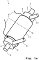
- FIG. 1a An exemplary embodiment of a heat exchanger 1, which is designed as a fluid-fluid heat exchanger, is shown.
- a line 3 for a first fluid runs inside in the longitudinal axis alignment.
- This line 3 can be integrated into a fluid circuit with its front connection end 5 and its rear connection end 7.
- the line 3 is designed as a refrigerant line. It is suitable for allowing refrigerants such as R-134a, R-1234yf or R-744 to flow through it. It is tubular with a circular cross section. Your pipe wall is made of steel or another suitable, common material.
- the line 3 runs coaxially with the line 9 for a second fluid in this line 9.
- the line 9 is also tubular with a circular cross section, which is correspondingly larger than that of the line 3 for the first fluid.
- the connecting piece 11 that protrudes laterally from the line 9 for a second fluid in the front area and the connecting piece 13 that projects laterally in the rear area serve to connect to a fluid circuit for a second fluid, so that the line 9 can be integrated into a fluid circuit for a second fluid.
- It is designed as a coolant line for a coolant, such as a water-glycol mixture or deionized water, as a second fluid.
- Your pipe wall is made of a suitable material such as steel.
- the line 3 for the first fluid running in the line 9 for the second fluid is arranged in a heat exchange connection for a heat exchange of a first fluid with a second fluid.
- Heat can pass through the pipe wall of line 3 the second fluid flowing in the line 9 can be exchanged with a first fluid flowing through the line 3 running coaxially in it.
- An electrical heating element 15 designed as a heating foil is arranged outside around the line 9 for the second fluid with one surface of it. This electrical heating element 15, which lies around the line 9 for a second fluid as a jacket, is therefore arranged in a thermally conductive connection with this line 9. This allows a second fluid flowing in line 9 to be heated.
- the electrical lines 17 are used to connect an electrical energy source or an electrical energy storage device for supplying power to the electrically operable heating element 15.
- the electrically operable heating element 15 on the outside of the line 9 for the second fluid such as a heating rod with a heat-conducting plate connected in a heat-conducting manner or a heating wire wound around the at least one line 9 for the second fluid is conceivable.
- Fig. 1b is a view of a cross section in the cutting plane through the dashed line in Fig. 1a line A running perpendicular to the longitudinal axis of the in Fig. 1a heat exchanger 1 shown.
- the line 3 for a first fluid In the center is the line 3 for a first fluid, with its circular cross section.
- the line 3 lies coaxially in the line 9 for a second fluid, which also has a circular cross section.
- the cross sections of the two lines 3 and 9 are concentric.
- a second fluid would therefore flow through the annular area between the cross-sectional areas of the pipe walls of the two lines 3 and 9.
- the outer ring around the line 9 for the second fluid forms a thermally conductive connection to it electrically operable heating element 15 designed as a heating foil.
- Fig. 2 a view of a cross section in the cutting plane perpendicular to the longitudinal axis of a further exemplary embodiment of a heat exchanger 1 is shown.
- the heat exchanger 1 is constructed in exactly the same way as the one in. except for the square cross-section of the line 9 for a second fluid and thus also the square cross-section of the electrical heating element 15, which acts as a heating foil on the outside of the line 9 Fig. 1a heat exchanger 1 shown.
- the line 3 for a first fluid is located coaxially to one another in the line 9 for a second fluid.
- the line 9 can be integrated into a further fluid circuit for a second fluid.
- the line 9 can be integrated into a further fluid circuit for a second fluid.
- four heating elements 15 with heat-conducting plates connected to the respective heating element in a heat-conducting manner, which each rest on one of the four outer surfaces of the line 9 running in the longitudinal direction of the line for a second fluid, are also conceivable as electrically operable heating elements 15.
- Fig. 3 a view of a cross section in the cutting plane perpendicular to the longitudinal axis of an exemplary embodiment of a heat exchanger 1 is shown.
- the line 3 for a first fluid lies coaxially to one another in the line 9 for a second fluid.
- the line 9 can be integrated into a further fluid circuit for a second fluid. Outside the line 3 for a first fluid and in a heat-conducting connection within the line 9 for a second fluid, three electrically operable heating elements 15 are arranged, without being limited to the number.
- the heating elements 15 are designed as electrically operable heating elements whose longitudinal axes run parallel to the longitudinal axis of the line 9 for a second fluid. Your heat-conducting connection with the line 9 for a second fluid exists directly between the heating elements 15 and the second fluid within the line 9 when the second fluid flows through the line 9. As a variant, particularly good heat-conducting materials, such as heat-conducting plates, are available to improve the heat-conducting connection the heating elements 15 conceivable. Other types of electrically operable heating elements 15 are also conceivable, such as a heating foil on the inside of the pipe wall of the line 9 for the second fluid.
- Fig. 4 a view of a cross section in the cutting plane perpendicular to the longitudinal axis of a further exemplary embodiment of a heat exchanger 1 is shown.
- the line 3 for a first fluid runs as a central channel with a square cross-section in an elongated cuboid containing a highly heat-conducting material 29, such as aluminum, the external shape of which essentially represents that of the heat exchanger 1.
- the line 3 for a first fluid is in a fluid circuit for a first fluid integrable. It is surrounded by four segments 10 of the line 9 for a second fluid.
- the four segments 10 do not completely enclose the line 3 for a first fluid, but surround it to a large extent.
- These four segments 10 run with their longitudinal axes parallel to the longitudinal axis of the line 3 for a first fluid. They each have a rectangular cross section and are each designed as a channel in the highly heat-conducting material 29 of the heat exchanger 1, which is essentially shaped as a cuboid. There is a heat exchange connection to the central line 3 for a first fluid through the highly heat-conducting material 29 on one side of a respective segment 10 of the line 9 for the second fluid. Between two adjacent segments 10 of the line 9 for the second fluid, an electrically operable heating element 15 is arranged in a heat-conducting connection.
- These four heating elements 15 are inserted as heating elements into the heat exchanger 1, which is essentially shaped as a cuboid, each in the area of one of its longitudinal edges.
- the longitudinal axes of the heating elements 15 run parallel to the longitudinal axes of the four segments 10 of the line 9 for the second fluid.
- the heating elements 15 are arranged outside the line 3 for a first fluid.
- the four segments 10 of the line 9 for a second fluid are each brought together at their front and rear ends to form a line 9 with connection option for integration into a fluid circuit for the second fluid, which is due to the illustration in Fig. 4 is not visible.
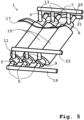
- a heat exchanger 1 which is designed as a fluid-fluid heat exchanger.
- the respective lines 3 for a first fluid which can be, for example, a refrigerant such as R-134a, R-1234yf or R-744, has a circular cross section in the section plane perpendicular to its longitudinal axis.
- the respective front connection ends 5 of the lines 3 for the first fluid are connected to a front manifold 19, which can be connected to a fluid circuit.
- the respective rear connection ends 7 of the lines 3 for the first fluid are connected to a rear manifold 21, which can be connected to the same fluid circuit.
- This means that the lines 3 for a first fluid can be integrated into a fluid circuit.
- the lines 9 for a second fluid can be integrated into a further fluid circuit via a front manifold 23 and a rear manifold 25.
- Their respective front connecting pieces 11 open into the front manifold 23 and their respective rear connecting pieces 13 open into the rear manifold 25.
- the respective lines 9 for a second fluid have a circular cross section in the cutting plane perpendicular to their longitudinal axis.
- Heat exchange connection for a heat exchange of a first fluid with a second fluid through the pipe wall of the respective line 3 for a first fluid, which runs coaxially in the respective line 9 for the second fluid.
- an electrically operable heating element 15 is arranged in each case.
- the respective heating element 15 comprises an electrically operable heating foil, one surface of which rests on the outer line wall of the respective line 9 for a second fluid in a heat-conducting connection. This allows a second fluid flowing through line 9, such as deionized water, to be heated as a coolant.
- the three electrically operable heating elements 15 can be connected to an electrical energy source or an electrical energy storage device via the electrical lines 17.
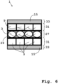
- Fig. 6 a view of a vertical section of an exemplary embodiment of a heat exchanger 1 designed as a plate heat exchanger is shown.
- the middle layer 27 includes, without being limited to the number, four lines 3 for a first fluid. These lines 3 each have an oval cross section relative to their longitudinal axis. Other suitable forms of a line cross section are also conceivable.
- the lines 3 for a first fluid are designed as channel lines through a highly heat-conducting material 29, such as aluminum, in the middle layer 27.
- the lines 3 for a first fluid can therefore be integrated into a fluid circuit.
- each with four lines 9 for a second fluid in layers.
- These lines 9 have rectangular cross sections without being limited to this shape.
- There is also a different number of lines 9 for a second fluid in a layer 31 is conceivable.
- the walls of the lines 9 are made of a material that conducts heat well, such as aluminum.
- the lines 3 for a first fluid of the middle layer 27 and the lines 9 for a second fluid of the adjacent layer 31 are therefore arranged in such a way that there is in each case a heat exchange connection for a heat exchange between a first and a second fluid.
- the lines 9 for a second fluid point in Fig. 6 Front and rear connection ends, not shown, for connection to another fluid circuit.
- the lines 9 for a second fluid can therefore be integrated into another fluid circuit.
- the top and bottom layers 33 of the heat exchanger 1 each include an electrically operable heating element 15 designed as a heating foil. These layers 33 are each adjacent in layers to a layer 31 with lines 9 for a second fluid. There is a heat-conducting connection between a heating element 15 and the lines 9 for a second fluid of the adjacent layer 31, so that a second fluid flowing through can be heated.
- Both layers 31 with the lines 9 for the second fluid are each arranged in a heat-conducting manner in a layer-like manner adjacent between a layer 33 comprising an electrically operable heating element 15 and a layer 27 comprising lines 3 for the first fluid.
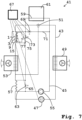
- FIG. 7 an exemplary embodiment of a circulation system 41 with a first fluid circuit 43 designed as a refrigerant circuit and a second fluid circuit 45 designed as a coolant circuit is shown.
- a Compressor 47 In the first fluid circuit 43 there are a Compressor 47, a condenser/gas cooler 49, an expansion element 51 designed as a thermostatic expansion valve and an evaporator 53 are arranged connected via refrigerant lines, so that a refrigerant such as R-134a, R-1234yf or R-744 can circulate therein as the first fluid.
- a refrigerant such as R-134a, R-1234yf or R-744 can circulate therein as the first fluid.
- a heat exchanger 1 designed as a fluid-fluid heat exchanger is integrated in the low-pressure region downstream of the expansion element 51 and upstream of the evaporator 53 in the first fluid circuit 43 with the line 3 for the first fluid.
- the heat exchanger 1 corresponds to the in Fig. 5 heat exchanger shown, as above Fig. 5 described.
- This heat exchanger 1 is also integrated into the second fluid circuit 45.
- a fluid delivery device 55 as a coolant pump, a further heat exchanger 57 and a heat exchange connection 59 are also arranged to form an object 61 designed as an aggregate, such as a traction battery, connected via coolant lines.
- the further heat exchanger 57 serves for heat exchange between the first and second fluid. It can be bypassed in the second fluid circuit 45 by appropriately switching the valve 63 in the bypass 65.
- the valve 63 is regulated by the controller 67, which is designed as a controller with a processor.
- the heat-conducting connection 59 to the object 61 designed as an aggregate can be bypassed by appropriately switching the valve 69 in the bypass 71.
- the valve 69 is controlled by the control 67.
- the heat exchanger 1 is closed in the second fluid circuit 45 by appropriately switching the valve 73 in the bypass 75 the lines 9 of the heat exchanger 1 integrated into the second fluid circuit 45 can be bypassed.
- the valve 73 is controlled by the control 67. This also regulates the supply of electrical energy to the electrically operable heating elements 15 of the heat exchanger 1. The electrical energy for this is supplied by the electrical energy storage 77 designed as a rechargeable battery.
- the heating elements 15 of the heat exchanger 1 are in a heat-conducting connection to its lines 9 for the second fluid, which are integrated into the second fluid circuit 45, so that coolant flowing through there can be heated by the electrically operable heating elements 15.
- the control 67 regulates the compressor 47.
- the second fluid flowing through which is a coolant
- first Fluid flowing colder refrigerant can be cooled.
- Regulation 67 receives from in Fig. 7
- temperature sensors not shown, measure the temperatures of the object 61 to be tempered and of the second fluid and determine from this whether the second fluid should be heated or cooled or neither heated nor cooled, and accordingly regulates the valves 63, 69 and 73, the compressor 47 and the heating elements 15 of the heat exchanger 1.
- the connections for regulation are marked with dashed lines Fig. 7 shown.
- the circulation system 41 is intended for a land vehicle, such as an electric wheel loader.
- FIG. 8 an exemplary embodiment of a further circuit system 41 with a first fluid circuit 43 designed as a coolant circuit and a second fluid circuit 45 designed as a coolant circuit is shown.
- This circulatory system 41 essentially corresponds to that in Fig. 7 shown.
- the heat exchanger 1 corresponds to the in Fig. 5 heat exchanger shown, as above Fig. 5 described.
- Fig. 1a or as in Fig. 6 Heat exchanger shown 1.
- a bypass with a valve in the second fluid circuit 45 to the heat exchanger 1 exists in the in Fig.
- the circulatory system 41 can be regulated in such a way that the object 61, designed as an aggregate, can be tempered in accordance with the temperature range specified for it by the second fluid in the second fluid circuit 45.
- the circuit system 41 is intended for a land vehicle such as an electric truck.
- Fig. 9 is an embodiment of a vehicle 91 with a circulation system 41, as in Fig. 7 shown, depicted.
- Vehicle 91 is an electric wheel loader.
- the object 61 designed as a traction battery can be in the second fluid circuit 45 of the circulatory system 41 via the heat exchange connection 59 Fig. 7 be tempered as described.
- a vehicle 91 is, for example, a forklift or an agricultural tractor with a traction battery as the object 61 to be tempered.
Description
Die Erfindung betrifft Wärmetauscher mit wenigstens einer in einen Fluidkreislauf integrierbaren Leitung für ein erstes Fluid und mit wenigstens einer dazu in Wärmetauschverbindung für einen Wärmetausch eines ersten mit einem zweiten Fluid angeordneten in einen weiteren Fluidkreislauf integrierbaren Leitung für ein zweites Fluid. Derartige auch als Fluid-Fluid-Wärmetauscher bezeichnete Wärmetauscher werden insbesondere bei Klimaanlage für Fahrzeuge mit einem Kreislaufsystem mit Kältemittelkreislauf und Kühlkreislauf zum Wärmetausch zwischen den Fluiden der beiden Kreisläufe verwendet. Ferner betrifft die Erfindung ein Kreislaufsystem und ein Fahrzeug damit. Das Kreislaufsystem umfasst einen ersten Fluidkreislauf mit wenigstens einem Verdichter, einem Kondensator/Gaskühler und einem Expansionsorgan für ein darin als Kältemittel zirkulierendes erstes Fluid sowie einen zweiten Fluidkreislauf mit wenigstens einer Fluidfördereinrichtung für ein darin als Kühlmittel zirkulierendes zweites Fluid, wobei der Wärmetausch zwischen beiden Fluiden über einen in beide Fluidkreisläufe integrierten Wärmetauscher erfolgt.The invention relates to heat exchangers with at least one line for a first fluid that can be integrated into a fluid circuit and with at least one line for a second fluid that can be integrated into a further fluid circuit in a heat exchange connection for a heat exchange of a first fluid circuit arranged with a second fluid. Such heat exchangers, also known as fluid-fluid heat exchangers, are used in particular in air conditioning systems for vehicles with a circulation system with a refrigerant circuit and a cooling circuit for heat exchange between the fluids of the two circuits. The invention further relates to a circulatory system and a vehicle therewith. The circuit system comprises a first fluid circuit with at least one compressor, a condenser/gas cooler and an expansion element for a first fluid circulating therein as a coolant, and a second fluid circuit with at least one fluid delivery device for a second fluid circulating therein as a coolant, the heat exchange between the two fluids being carried out via a heat exchanger integrated into both fluid circuits takes place.
Bekannt sind Wärmetauscher, die als Fluid-Fluid-Wärmetauscher dem Wärmetausch zwischen zwei Fluidkreisläufen dienen. So ist in
In
In
Der im Patentanspruch 1 angegebenen Erfindung liegt das Problem zugrunde, einen Wärmetauscher mit wenigstens einer in einen Fluidkreislauf integrierbaren Leitung für ein erstes Fluid und mit wenigstens einer dazu in Wärmetauschverbindung für einen Wärmetausch eines ersten mit einem zweiten Fluid angeordneten in einen weiteren Fluidkreislauf integrierbaren Leitung für ein zweites Fluid, der insbesondere hinsichtlich einer Temperierung bezüglich des zweiten Fluides verbessert ist, bereitzustellen.The invention specified in
Entsprechende Probleme für ein Kreislaufsystem und für ein Fahrzeug liegen den in den Patentansprüchen 4 und 8 angegebenen Erfindungen zugrunde.Corresponding problems for a circulatory system and for a vehicle are the basis of the inventions specified in claims 4 and 8.
Das der im Patentanspruch 1 angegebenen Erfindung zugrundeliegende Problem wird mit den im Patentanspruch 1 aufgeführten Merkmalen gelöst. Dadurch dass der Wärmetauscher mit wenigstens einer in einen Fluidkreislauf integrierbaren Leitung für ein erstes Fluid und mit wenigstens einer dazu in Wärmetauschverbindung für einen Wärmetausch eines ersten mit einem zweiten Fluid angeordneten in einen weiteren Fluidkreislauf integrierbaren Leitung für ein zweites Fluid zumindest ein elektrisch betreibbares Heizelement, das in Wärmeleitverbindung mit zumindest einer der wenigstens einen Leitung für ein zweites Fluid angeordnet ist, umfasst, und der Wärmetauscher für eine Integration in ein Kreislaufsystem derart ausgebildet und vorgesehen ist, dass die Leitung für das erstes Fluid in den Niedrigdruckbereich eines ersten Fluidkreislaufs mit wenigstens einem Verdichter, einem Kondensator/Gaskühler und einem Expansionsorgan für das darin als Kältemittel zirkulierende erste Fluid und die Leitung für das zweites Fluid in einen zweiten Fluidkreislauf mit wenigstens einer Fluidfördereinrichtung für das darin als Kühlmittel zirkulierende zweite Fluid zu integrieren sind, und wenigstens eine Leitung für ein erstes Fluid koaxial in wenigstens einer Leitung für ein zweites Fluid angeordnet ist und in Wärmeleitverbindung außen an wenigstens einer Leitung für ein zweites Fluid, in der koaxial eine Leitung für ein erstes Fluid verläuft, das wenigstens eine elektrisch betreibbare Heizelement angeordnet ist, wobei das wenigstens eine elektrisch betreibbare Heizelement
einen um die wenigstens eine Leitung für ein zweites Fluid gewundenen Heizdraht oder eine um die wenigstens eine Leitung für ein zweites Fluid herum mit seiner einen Oberfläche anliegende Heizfolie umfasst, wird das Problem gelöst.The problem underlying the invention specified in
a heating wire wound around the at least one line for a second fluid or a heating foil around the at least one line for a second fluid with its surface resting on one surface, the problem is solved.
In Wärmeleitverbindung mit einer Leitung ist unter anderem auch bei einer Ausführungsform so zu verstehen, bei der die Wärmeleitverbindung derart ausgebildet ist, dass sie bei durch die Leitung strömenden zweiten Fluid direkt zwischen einem Heizelement und dem zweiten Fluid innerhalb der Leitung besteht.A heat-conducting connection with a line is also to be understood, among other things, in an embodiment in which the heat-conducting connection is designed in such a way that that when the second fluid flows through the line, it exists directly between a heating element and the second fluid within the line.
Die Erfindung hat den Vorteil, dass das wenigstens eine elektrisch betreibbare Heizelement, das durch die Wärmeleitverbindung mit wenigstens einer Leitung für ein zweites Fluid zum Erwärmen des zweiten Fluides geeignet ist, im Wärmetauscher integriert ist. Der erfindungsgemäße Wärmetauscher ermöglicht also einerseits eine Kühlung eines zweiten Fluides durch ein erstes Fluid und anderseits die Erwärmung des zweiten Fluides durch das wenigstens eine elektrisch betreibbare Heizelement. Eine zusätzliche elektrisch betreibbare Heizeinrichtung in einem Fluidkreislauf für das zweite Fluid ist somit für eine bedarfsweise Erwärmung des zweiten Fluides entbehrlich. Durch den erfindungsgemäßen Wärmetauscher werden also insbesondere hinsichtlich einer Temperierung bezüglich des zweiten Fluides vorteilhaft Platz, Material und Gewicht sowie Kosten gespart. Die koaxiale Anordnung der Leitungen ist besonders platz- und materialsparend und zugleich existiert eine effektive Wärmetauschverbindung zwischen den Leitungen und bei Betrieb somit auch zwischen beiden Fluiden.The invention has the advantage that the at least one electrically operable heating element, which is suitable for heating the second fluid due to the heat-conducting connection with at least one line for a second fluid, is integrated in the heat exchanger. The heat exchanger according to the invention therefore enables, on the one hand, cooling of a second fluid by a first fluid and, on the other hand, heating of the second fluid by the at least one electrically operable heating element. An additional electrically operable heating device in a fluid circuit for the second fluid is therefore unnecessary for heating the second fluid as required. The heat exchanger according to the invention therefore advantageously saves space, material and weight as well as costs, particularly with regard to temperature control with respect to the second fluid. The coaxial arrangement of the lines is particularly space- and material-saving and at the same time there is an effective heat exchange connection between the lines and, during operation, between the two fluids.
Die äußere Oberfläche der Leitung für ein zweites Fluid ist üblicherweise deren größte. Das wenigstens eine elektrisch betreibbare Heizelement lässt sich von außen gut aufbringen und ein unerwünschtes Heizen auch eines ersten Fluides in der inneren Leitung erfolgt so nicht oder ist zumindest möglichst gering.The outer surface of the conduit for a second fluid is usually its largest. The at least one electrically operable heating element can be easily applied from the outside and undesirable heating of a first fluid in the inner line does not occur or is at least as low as possible.
Die erfindungsgemäßen Arten der Ausführungen eines elektrisch betreibbaren Heizelements sind effektiv, kostengünstig und einfach zu bewerkstelligen. Besonders effektiv, kostengünstig und einfach zu bewerkstelligen sowie zu handhaben ist die Ausgestaltung, bei der das wenigstens eine als Heizfolie ausgebildete elektrisch betreibbare Heizelement um die wenigstens eine Leitung für ein zweites Fluid, in der koaxial eine Leitung für ein erstes Fluid verläuft, herum mit seiner einen Oberfläche anliegend angeordnet ist.The types of designs of an electrically operable heating element according to the invention are effective, inexpensive and easy to implement. Particularly effective, inexpensive and easy to do The configuration in which the at least one electrically operable heating element designed as a heating foil is arranged with its one surface adjacent to the at least one line for a second fluid, in which a line for a first fluid runs coaxially, is also to be handled.
Es sind die wenigstens eine in einen Fluidkreislauf integrierbare Leitung für ein erstes Fluid als Kältemittelleitung und die wenigstens eine in einen weiteren Fluidkreislauf integrierbare Leitung für ein zweites Fluid als Kühlmittelleitung ausgebildet. Damit ist der Wärmetauscher in einen Kältemittel-Kreislauf mit einem Kältemittel wie zum Beispiel R-134a, R-1234yf oder R-744 als erstes Fluid und in einen Kühlmittelkreislauf mit Kühlmittel wie beispielsweise ein Wasser-Glykol-Gemisch als zweites Fluid zum Wärmetausch zwischen den beiden Fluidkreisläufen integrierbar.The at least one line for a first fluid that can be integrated into a fluid circuit is designed as a coolant line and the at least one line for a second fluid that can be integrated into a further fluid circuit is designed as a coolant line. This means that the heat exchanger is in a refrigerant circuit with a refrigerant such as R-134a, R-1234yf or R-744 as the first fluid and in a coolant circuit with coolant such as a water-glycol mixture as the second fluid for heat exchange between the Can be integrated into both fluid circuits.
In den Unteransprüchen sind vorteilhafte Ausgestaltungen, Weiterbildungen und Verbesserungen des jeweiligen Gegenstandes der Erfindung angegeben.Advantageous refinements, further developments and improvements of the respective subject matter of the invention are specified in the subclaims.
Besonders vorteilhaft ist bei einer Anordnung jeweils ein kreisrunder Querschnitt der beiden Leitungen in Schnittebene senkrecht zu ihrer Längsachse, denn mit einem derartigen Querschnitt sind die Leitungen wenig schadanfällig, besonders druckbeständig und durch ihre Zylindersymmetrie gleichmäßig hinsichtlich des Wärmetauschs. Nach einer ebenfalls vorteilhaften Alternative weist die wenigstens eine Leitung für ein zweites Fluid, in der koaxial wenigstens eine Leitung für ein erstes Fluid verläuft, einen rechteckigen vorzugsweise quadratischen Querschnitt in Schnittebene senkrecht zu ihrer Längsachse auf. Dadurch ist das Verhältnis von Oberfläche zu Volumen für ein effektives Heizen eines zweiten Fluides mit auf der äußeren Oberfläche angebrachten Heizelement/en vorteilhaft. So können auch elektrisch betreibbare Heizelemente mit starrer planer Fläche außen auf der Leitung für ein zweites Fluid angebracht werden.In an arrangement, it is particularly advantageous to have a circular cross section of the two lines in the cutting plane perpendicular to their longitudinal axis, because with With such a cross-section, the lines are less susceptible to damage, are particularly pressure-resistant and, thanks to their cylindrical symmetry, are uniform in terms of heat exchange. According to a likewise advantageous alternative, the at least one line for a second fluid, in which at least one line for a first fluid runs coaxially, has a rectangular, preferably square cross-section in the section plane perpendicular to its longitudinal axis. As a result, the ratio of surface to volume is advantageous for effective heating of a second fluid with heating element(s) attached to the outer surface. Electrically operated heating elements with a rigid, flat surface can also be attached to the outside of the line for a second fluid.
Alternativ ist ebenfalls bei der koaxialen Anordnung der Leitungen eine Ausgestaltung des Wärmetauschers von Vorteil, bei der außerhalb der Leitung für ein erstes Fluid und in Wärmeleitverbindung innerhalb der wenigstens einen koaxial verlaufenden Leitung für ein zweites Fluid zumindest ein des wenigstens einen elektrisch betreibbaren Heizelements angeordnet ist. Dadurch besteht bei durch die Leitung strömenden zweiten Fluid eine Wärmeleitverbindung direkt zwischen dem/den Heizelement/en und dem zweiten Fluid, was ein besonders effektives Heizen des zweiten Fluides ermöglicht.Alternatively, with the coaxial arrangement of the lines, a design of the heat exchanger is also advantageous, in which at least one of the at least one electrically operable heating element is arranged outside the line for a first fluid and in a heat-conducting connection within the at least one coaxially extending line for a second fluid. As a result, when the second fluid flows through the line, there is a heat-conducting connection directly between the heating element(s) and the second fluid, which enables particularly effective heating of the second fluid.
Gemäß einer vorteilhaften Weiterbildung des erfindungsgemäßen Wärmetauschers sind mehrere der koaxial jeweils eine Leitung für das erste Fluid enthaltende Leitungen für das zweite Fluid bezüglich ihrer Längsachsen parallel nebeneinander angeordnet. Durch die Aufteilung in mehrere parallele Leitungen ist der Wärmetausch zwischen einem ersten und zweiten Fluid sowie die Heizmöglichkeit eines zweiten Fluides durch die elektrisch betreibbaren Heizelemente besonders effektiv. Damit ist die Oberfläche im Verhältnis zum Volumen im Vergleich zu nur einen gleichlangen Koaxialleitung vergrößert. Der Wärmetauscher kann dadurch bei gleicher Effektivität vorteilhaft kurz sein.According to an advantageous development of the heat exchanger according to the invention, several of the lines for the second fluid, each containing a line for the first fluid, are arranged coaxially next to one another with respect to their longitudinal axes. Due to the division into several parallel lines, the heat exchange between a first and second fluid as well as the possibility of heating a second fluid through the electrically operated heating elements are particularly effective. This means that the surface area is increased in relation to the volume compared to just a coaxial line of the same length. The heat exchanger can therefore be advantageously short with the same effectiveness.
Vorzugsweise ist die Leitung für ein erstes Fluid von mindestens zwei mit dazu paralleler Längsachse verlaufenden Leitungen für ein zweites Fluid oder von mindestens zwei mit dazu paralleler Längsachse verlaufenden Segmenten einer Leitung für ein zweites Fluid zumindest teilweise umgeben, und zwischen wenigstens zwei dieser Leitungen für ein zweites Fluid oder zwischen wenigstens zwei der Segmente einer Leitung für ein zweites Fluid ist in Wärmeleitverbindung zumindest ein des wenigstens einen elektrisch betreibbaren Heizelements angeordnet. Eine derartige Ausgestaltung des Wärmetauschers ist besonders kompakt.Preferably, the line for a first fluid is at least partially surrounded by at least two lines for a second fluid running with a longitudinal axis parallel thereto or by at least two segments of a line for a second fluid running with a longitudinal axis parallel thereto, and between at least two of these lines for a second fluid Fluid or between at least two of the segments of a line for a second fluid, at least one of the at least one electrically operable heating element is arranged in a thermally conductive connection. Such a design of the heat exchanger is particularly compact.
Nach einer vorteilhaften Ausführung des Wärmetauschers ist er als Plattenwärmetauscher ausgebildet, wobei eine Schicht des Wärmetauschers zumindest eine der wenigstens einen Leitung für ein zweites Fluid umfasst und diese Schicht schichtförmig angrenzend zwischen einer zumindest ein elektrisch betreibbares Heizelement umfassenden Schicht und einer zumindest eine der wenigstens einen Leitung für das erste Fluid umfassenden Schicht wärmeleitend angeordnet ist. Ein derartiger Plattenwärmetauscher ist kompakt und effektiv. Möglich ist auch eine Ausführung umfassend mehrere sich überlappender solcher Schichtfolgen mit jeweils zur im Schichtstapel benachbarten umgekehrter Schichtreihenfolge, also jeweils mit einer Schicht mit Leitung für ein zweites Fluid zwischen einer Schicht mit elektrisch betreibbarem Heizelement und einer Schicht mit Leitung für ein erstes Fluid. Vorzugsweise umfasst die wenigstens ein elektrisch betreibbares Heizelement umfassende Schicht eine Heizfolie als das elektrisch betreibbare Heizelement. Eine Heizfolie lässt sich gut als oder in eine/r Schicht in einen Plattenwärmetauscher anordnen und ist insbesondere wegen ihrer großen beim Heizen wirksamen Fläche besonders effektiv.According to an advantageous embodiment of the heat exchanger, it is designed as a plate heat exchanger, wherein a layer of the heat exchanger comprises at least one of the at least one line for a second fluid and this layer is adjacent in layers between a layer comprising at least one electrically operable heating element and at least one of the at least one line is arranged in a heat-conducting manner for the first fluid-comprising layer. Such a plate heat exchanger is compact and effective. It is also possible to have an embodiment comprising several overlapping layer sequences of this type, each with the reverse layer order to the one adjacent in the layer stack, i.e. each with a layer with a line for a second fluid between a layer with an electrically operable heating element and a layer with a line for a first fluid. Preferably, it comprises at least one electrically operable heating element comprehensive layer a heating foil as the electrically operated heating element. A heating foil can be easily arranged as or in a layer in a plate heat exchanger and is particularly effective because of its large area effective for heating.
Das der im Patentanspruch 4 angegebenen Erfindung zugrundeliegende Problem wird mit den im Patentanspruch 4 aufgeführten Merkmalen gelöst. Dadurch dass das Kreislaufsystem mit einem ersten Fluidkreislauf mit wenigstens einem Verdichter, einem Kondensator/Gaskühler und einem Expansionsorgan für ein darin als Kältemittel zirkulierendes erstes Fluid sowie mit einem zweiten Fluidkreislauf mit wenigstens einer Fluidfördereinrichtung für ein darin als Kühlmittel zirkulierendes zweites Fluid, einen erfindungsgemäßen Wärmetauscher aufweist, wobei dieser in den Niedrigdruckbereich des ersten Fluidkreislaufs und in den zweiten Fluidkreislauf integriert ist, und das wenigstens eine Heizelement dieses Wärmetauschers mit elektrischer Energie aus einer elektrischen Energiequelle/-speicher betreibbar ist, wird das Problem gelöst. Als Vorteile eines derartigen Kreislaufsystems gelten entsprechend die oben aufgeführten Vorteile für einen erfindungsgemäßen Wärmetauscher. Insbesondere ist eine zusätzliche elektrische Heizeinrichtung in dem Fluidkreislauf für das zweite Fluid für eine bedarfsweise Erwärmung des zweiten Fluides entbehrlich. Es werden durch die erfindungsgemäße Integration eines erfindungsgemäßen Wärmetauschers in das Kreislaufsystem also vor allem hinsichtlich einer Temperierung bezüglich des zweiten Fluides vorteilhaft Platz, Material, Gewicht sowie Kosten gespart.The problem underlying the invention specified in claim 4 is solved with the features listed in claim 4. The circulation system has a heat exchanger according to the invention with a first fluid circuit with at least one compressor, a condenser/gas cooler and an expansion element for a first fluid circulating therein as a coolant and with a second fluid circuit with at least one fluid delivery device for a second fluid circulating therein as a coolant , whereby this is integrated into the low-pressure region of the first fluid circuit and into the second fluid circuit, and the at least one heating element of this heat exchanger can be operated with electrical energy from an electrical energy source/storage, the problem is solved. The advantages of such a circulation system are the advantages listed above for a heat exchanger according to the invention. In particular, an additional electrical heating device in the fluid circuit for the second fluid is unnecessary for heating the second fluid as required. The integration of a heat exchanger according to the invention into the circulatory system advantageously saves space, material, weight and costs, especially with regard to temperature control with regard to the second fluid.
In den Unteransprüchen sind vorteilhafte Ausgestaltungen, Weiterbildungen und Verbesserungen des jeweiligen Gegenstandes der Erfindung angegeben.Advantageous refinements, further developments and improvements of the respective subject matter of the invention are specified in the subclaims.
Vorzugsweise ist im zweiten Fluidkreislauf für das zweite Fluid eine mittels Ventil schaltbarer Bypass zur wenigstens einen in den zweiten Fluidkreislauf integrierten Leitung des erfindungsgemäßen Wärmetauschers angeordnet und/oder ist im ersten Fluidkreislauf für das erste Fluid eine mittels Ventil schaltbarer Bypass zur wenigstens einen in den ersten Fluidkreislauf integrierten Leitung dieses Wärmetauschers angeordnet. Ein derartiger Bypass ermöglicht die Abkopplung des jeweiligen aktiven Teils des Fluidkreislaufs für das erste und/oder zweite Fluid vom erfindungsgemäßen Wärmetauscher. Damit ist eine Temperierung des zweiten Fluides flexibler zu realisieren. Vorteilhaft umfasst das Kreislaufsystem zum Einstellen der Temperatur des zweiten Fluides eine Regelung ausgebildet zum Regeln des/der Ventil(s)/e für den wenigstens einen schaltbaren Bypass und zum Regeln des wenigstens einen elektrischen Heizelements des Wärmetauschers. Diese Regelung ermöglicht eine automatische Einstellung der Temperatur des zweiten Fluides, was insbesondere bei einer Ausführung des Kreislaufsystems mit einer Wärmetauschverbindung im zweiten Fluidkreislauf mit zumindest einem zu temperierenden Objekt eine Verbesserung darstellt. Das zumindest eine zu temperierende Objekt ist bevorzugt ein Aggregat eines Fahrzeugs, wie insbesondere eine Traktionsbatterie. Eine Traktionsbatterie sollte insbesondere hinsichtlich ihrer Effizienz und Haltbarkeit in einem bestimmten Temperaturbereich betrieben werden. Das erfindungsgemäße Kreislaufsystem ist für deren Temperierung besonders gut geeignet.Preferably, a bypass that can be switched by means of a valve to at least one line of the heat exchanger according to the invention integrated into the second fluid circuit is arranged in the second fluid circuit for the second fluid and/or a bypass that can be switched by means of a valve to at least one line in the first fluid circuit is arranged in the first fluid circuit for the first fluid integrated line of this heat exchanger. Such a bypass enables the respective active part of the fluid circuit for the first and/or second fluid to be decoupled from the heat exchanger according to the invention. This makes it possible to control the temperature of the second fluid more flexibly. For adjusting the temperature of the second fluid, the circulation system advantageously comprises a control system designed to regulate the valve(s) for the at least one switchable bypass and to regulate the at least one electrical heating element of the heat exchanger. This control enables the temperature of the second fluid to be adjusted automatically, which represents an improvement, particularly when the circuit system is designed with a heat exchange connection in the second fluid circuit with at least one object to be tempered. The at least one object to be tempered is preferably an aggregate of a vehicle, such as in particular a traction battery. A traction battery should be operated in a certain temperature range, particularly with regard to its efficiency and durability. The invention Circulation system is particularly well suited for temperature control.
Das dem erfindungsgemäßen Wärmetauscher zugrundeliegenden Problem entsprechende Problem für ein Fahrzeug wird durch ein Fahrzeug mit einem erfindungsgemäßen Kreislaufsystem gelöst. Besonders gut geeignet ist dafür ein Elektro- oder Hybridfahrzeug, wie insbesondere ein derartiger Radlader, mit einem erfindungsgemäßen Kreislaufsystem zum beispielsweise Temperieren einer Traktionsbatterie.The problem for a vehicle underlying the heat exchanger according to the invention is solved by a vehicle with a circulation system according to the invention. An electric or hybrid vehicle, such as a wheel loader of this type, with a circulation system according to the invention for, for example, temperature control of a traction battery, is particularly suitable for this.
Schließlich können die Merkmale der Unteransprüche zu Patentanspruch 1 im Wesentlichen frei miteinander und nicht durch die in den Ansprüchen vorliegende Reihenfolge festgelegt kombiniert werden, sofern sie unabhängig voneinander sind. Gleiches gilt für die Unteransprüche zu Patentanspruch 4.Finally, the features of the subclaims to claim 1 can be combined essentially freely with one another and not by the order in the claims, provided they are independent of one another. The same applies to the subclaims to patent claim 4.
Anhand der Zeichnungen werden Ausführungsbeispiele der Erfindung erläutert.Exemplary embodiments of the invention are explained using the drawings.
Es zeigen
-
Fig. 1a ein Ausführungsbeispiel eins erfindungsgemäßen Wärmetauschers, -
Fig. 1b eine Ansicht eines Querschnitts in Schnittebene senkrecht zur Längsachse des inFig. 1a dargestellten Ausführungsbeispiels eines Wärmetauschers, -
Fig. 2 eine Ansicht eines Querschnitts in Schnittebene senkrecht zur Längsachse eines weiteren Ausführungsbeispiels eines erfindungsgemäßen Wärmetauschers, -
Fig. 3 eine Ansicht eines Querschnitts in Schnittebene senkrecht zur Längsachse eines Ausführungsbeispiels eines Wärmetauschers der nicht erfindungsgemäß ist , -
Fig. 4 eine Ansicht eines Querschnitts in Schnittebene senkrecht zur Längsachse eines Wärmetauschers der nicht erfindungsgemäß ist , -
Fig. 5 ein weiteres Ausführungsbeispiel eines erfindungsgemäßen Wärmetauschers, -
Fig. 6 eine Ansicht eines vertikalen Schnitts von einem als Plattenwärmetauscher ausgebildeten Ausführungsbeispiel eines Wärmetauschers, -
Fig. 7 ein Ausführungsbeispiel eines erfindungsgemäßen Kreislaufsystems, -
Fig. 8 ein weiteres Ausführungsbeispiel eines erfindungsgemäßen Kreislaufsystems, und -
Fig. 9 ein Ausführungsbeispiel eines erfindungsgemäßen Fahrzeugs.
-
Fig. 1a an embodiment of a heat exchanger according to the invention, -
Fig. 1b a view of a cross section in the cutting plane perpendicular to the longitudinal axis of the inFig. 1a illustrated embodiment of a heat exchanger, -
Fig. 2 a view of a cross section in a section plane perpendicular to the longitudinal axis of another Embodiment of a heat exchanger according to the invention, -
Fig. 3 a view of a cross section in the cutting plane perpendicular to the longitudinal axis of an exemplary embodiment of a heat exchanger which is not according to the invention, -
Fig. 4 a view of a cross section in the cutting plane perpendicular to the longitudinal axis of a heat exchanger which is not according to the invention, -
Fig. 5 a further exemplary embodiment of a heat exchanger according to the invention, -
Fig. 6 a view of a vertical section of an exemplary embodiment of a heat exchanger designed as a plate heat exchanger, -
Fig. 7 an embodiment of a circulatory system according to the invention, -
Fig. 8 a further embodiment of a circulatory system according to the invention, and -
Fig. 9 an embodiment of a vehicle according to the invention.
Alle Zeichnungen sind schematisch zu verstehen. Auf maßstabsgetreue Abbildungen wurde zum Zwecke erhöhter Klarheit der Darstellung verzichtet.All drawings are to be understood schematically. Figures to scale have been used for the purpose of enlargement Clarity of presentation is waived.
In
In
In
In
In
In
Wärmetauschverbindung für einen Wärmetausch eines ersten mit einem zweiten Fluid durch die Rohrwand der jeweiligen Leitung 3 für ein erstes Fluid, die koaxial in der jeweiligen Leitung 9 für das zweite Fluid verläuft.Heat exchange connection for a heat exchange of a first fluid with a second fluid through the pipe wall of the
Um die jeweilige Leitung 9 für ein zweites Fluid herum, in der jeweils koaxial die Leitung 3 für ein erstes Fluid verläuft, ist jeweils ein elektrisch betreibbares Heizelement 15 angeordnet. Das jeweilige Heizelement 15 umfasst eine elektrisch betreibbare Heizfolie, deren eine Oberfläche an der äußeren Leitungswand der jeweiligen Leitung 9 für ein zweites Fluid in Wärmeleitverbindung anliegt. Dadurch kann ein durch die Leitung 9 strömendes zweites Fluid wie beispielsweise deionisiertes Wasser als Kühlmittel erwärmt werden. Die drei elektrisch betreibbaren Heizelemente 15 sind über die elektrischen Leitungen 17 an eine elektrischen Energiequelle oder einen elektrischen Energiespeicher anschließbar.Around the
In
In
In
In
Claims (9)
- Heat exchanger (1) comprising at least one line (3) for a first fluid, which line can be integrated into a fluid circuit, and comprising at least one line (9) for a second fluid, which line is arranged in heat-exchange connection with the first line for heat exchange of a first with a second fluid, and can be integrated into a further fluid circuit, wherein the heat exchanger (1) comprises at least one electrically operable heating element (15) which is arranged in heat-conducting connection with at least one of the at least one line (9) for a second fluid,
and the heat exchanger (1) is designed and provided for integration into a circuit system (41) in such a way that the line (3) for the first fluid is to be integrated into the low-pressure region of a first fluid circuit (43) comprising at least one compressor (47), a condenser/gas cooler (49) and an expansion member (51) for the first fluid circulating therein as refrigerant, and the line (9) for the second fluid is to be integrated in a second fluid circuit (45) comprising at least one fluid conveying device (55) for the second fluid circulating therein as coolant, and at least one line (9) for a first fluid is arranged coaxially in at least one line (9) for a second fluid, characterised in that the at least one electrically operable heating element (15) is arranged in heat-conducting connection on the outside on at least one line (9) for a second fluid in which a line (3) for a first fluid extends coaxially, and the at least one electrically operable heating element (15) comprises a heating wire that is wound around the at least one line (9) for a second fluid, or a heating film which rests, with its one surface, around the at least one line (9) for a second fluid. - Heat exchanger (1) according to claim 1, characterised in that the at least one line (3) for a first fluid, which is arranged in the at least one line (9) for a second fluid and so as to be coaxial therewith, has a circular cross section in the sectional plane perpendicular to its longitudinal axis, and the at least one line (9) for a second fluid has a circular or rectangular, preferably square, cross section in the sectional plane perpendicular to its longitudinal axis.
- Heat exchanger (1) according to either claim 1 or claim 2, characterised in that a plurality of the lines (9) for a second fluid, each containing one line (3) for a first fluid, are arranged in parallel and side-by-side with respect to their longitudinal axes.
- Circuit system (41) comprising a first fluid circuit (43) having at least one compressor (47), a condenser/gas cooler (49) and an expansion member (51) for a first fluid circulating therein as a refrigerant, and comprising a second fluid circuit (45) having at least one fluid conveying means (55) for a second fluid circulating therein as a coolant, characterised in that a heat exchanger (1) according to any of claims 1 to 3 is integrated in the low-pressure region of the first fluid circuit (43) and in the second fluid circuit (45), and the at least one heating element (15) of said heat exchanger (1) is operable using electrical energy from an electrical energy source/store (77).
- Circuit system (41) according to claim 4, characterised in that a bypass (75), switchable by means of a valve (73), to at least one line (9), integrated into the second fluid circuit (45), of the heat exchanger according to any of claims 1 to 3 is arranged in the second fluid circuit (45), for the second fluid, and/or a bypass (79), switchable by means of a valve (81, 83), to at least one line (3), integrated into the first fluid circuit (43), of said heat exchanger (1) is arranged in the first fluid circuit (43), for the first fluid, and, for adjusting the temperature of the second fluid, the circuit system (41) comprises a control system (67) designed for controlling the valve(s) (73, 81, 83) for the at least one switchable bypass (75, 79) and for controlling the at least one electrical heating element (15) of the heat exchanger (1).
- Circuit system (41) according to either claim 4 or claim 5, characterised in that it comprises a heat-exchange connection (59) in the second fluid circuit (43) to at least one object (61) of which the temperature is to be controlled.
- Circuit system (41) according to claim 6, characterised in that the at least one object (61) of which the temperature is to be controlled is a unit of a vehicle (91), such as in a particular a traction battery.
- Vehicle (91) comprising a circuit system (41) according to any of claims 4 to 7.
- Vehicle (91) according to claim 8, characterised in that it is an electric or hybrid vehicle, in particular a wheeled loader of this kind.
Applications Claiming Priority (1)
| Application Number | Priority Date | Filing Date | Title |
|---|---|---|---|
| DE202019102689.8U DE202019102689U1 (en) | 2019-05-13 | 2019-05-13 | Heat exchanger and circulation system for tempering |
Publications (3)
| Publication Number | Publication Date |
|---|---|
| EP3739276A1 EP3739276A1 (en) | 2020-11-18 |
| EP3739276B1 true EP3739276B1 (en) | 2024-01-03 |
| EP3739276C0 EP3739276C0 (en) | 2024-01-03 |
Family
ID=67145473
Family Applications (1)
| Application Number | Title | Priority Date | Filing Date |
|---|---|---|---|
| EP20172633.8A Active EP3739276B1 (en) | 2019-05-13 | 2020-05-02 | Heat exchanger and temperature control circuit system |
Country Status (3)
| Country | Link |
|---|---|
| EP (1) | EP3739276B1 (en) |
| CN (1) | CN111928699A (en) |
| DE (1) | DE202019102689U1 (en) |
Families Citing this family (5)
| Publication number | Priority date | Publication date | Assignee | Title |
|---|---|---|---|---|
| DE102021103483A1 (en) | 2021-02-15 | 2022-08-18 | Bayerische Motoren Werke Aktiengesellschaft | Air conditioning system for an electrically driven motor vehicle with a heat sink and a heating device, motor vehicle and method for operating an air conditioning system |
| CN113650528B (en) * | 2021-08-19 | 2023-12-26 | 浙江吉利控股集团有限公司 | Thermal management module, thermal management system and automobile |
| DE102021125688A1 (en) * | 2021-10-04 | 2023-04-06 | Schmöle GmbH | Heat exchanger and method for refueling a vehicle |
| WO2023169455A1 (en) * | 2022-03-08 | 2023-09-14 | 莱顿汽车部件(苏州)有限公司 | Heat exchanger, coolant heater, and method for forming heat exchanger and body thereof |
| DE102022111067A1 (en) | 2022-05-05 | 2023-11-09 | Audi Aktiengesellschaft | Heat exchanger with heating device for simultaneous heating of refrigerant and coolant, thermal management system and motor vehicle |
Citations (1)
| Publication number | Priority date | Publication date | Assignee | Title |
|---|---|---|---|---|
| DE4201944C2 (en) * | 1991-01-24 | 2003-04-24 | Asahi Glass Co Ltd | Flüssigkeitsheizeinrichtung |
Family Cites Families (13)
| Publication number | Priority date | Publication date | Assignee | Title |
|---|---|---|---|---|
| DE19829334C1 (en) | 1998-07-01 | 1999-10-21 | Konvekta Ag | Heat pump for solar water heating |
| SE516844C3 (en) * | 2000-07-07 | 2002-04-17 | Alfa Laval Ab | Plate heat / plate heat exchanger with electrically heated layers in double wall plate elements |
| US7661460B1 (en) * | 2003-12-18 | 2010-02-16 | Advanced Thermal Sciences Corp. | Heat exchangers for fluid media |
| WO2007014426A1 (en) * | 2005-08-02 | 2007-02-08 | Solacoil Pty Ltd | Heat pump and method of heating fluid |
| WO2009062710A1 (en) | 2007-11-13 | 2009-05-22 | Behr Gmbh & Co. Kg | Device for cooling a heat source of a motor vehicle |
| KR101608996B1 (en) * | 2010-01-11 | 2016-04-05 | 엘지전자 주식회사 | Heat exchanger |
| DE102011076737A1 (en) | 2011-05-30 | 2012-12-06 | Robert Bosch Gmbh | Apparatus for providing electrical energy to electric drive unit of electric hybrid vehicle e.g. passenger car, has electrical energy storage device that is coupled with fuel cell assembly by heat transfer assembly |
| DE102012017404A1 (en) * | 2012-09-03 | 2014-03-27 | GM Global Technology Operations, LLC (n.d. Ges. d. Staates Delaware) | Heat exchanger for motor vehicle air conditioning system, has inner tube and outer tube, which partially encloses inner tube by forming intermediate space through which heat exchange medium is flowed, where inner tube is multi-channel tube |
| DE102013109666A1 (en) | 2013-09-04 | 2015-03-05 | Pierburg Gmbh | Heating / cooling system for vehicles and method for operating a heating / cooling system for vehicles |
| CN203489539U (en) * | 2013-09-04 | 2014-03-19 | 节能概念有限公司 | Heat exchanger |
| FR3023364B1 (en) * | 2014-07-03 | 2016-08-19 | Valeo Systemes Thermiques | DUAL CIRCULATION THERMAL EXCHANGER AND CORRESPONDING THERMAL MANAGEMENT INSTALLATION |
| FR3026165B1 (en) * | 2014-09-24 | 2017-06-02 | Commissariat Energie Atomique | DEVICE FOR THERMALLY TREATING A FLUID WITH REDUCED ENERGY CONSUMPTION |
| DE102017118424A1 (en) | 2017-08-13 | 2019-02-14 | Konvekta Aktiengesellschaft | Circulatory system for a fuel cell vehicle |
-
2019
- 2019-05-13 DE DE202019102689.8U patent/DE202019102689U1/en active Active
-
2020
- 2020-05-02 EP EP20172633.8A patent/EP3739276B1/en active Active
- 2020-05-12 CN CN202010397346.5A patent/CN111928699A/en active Pending
Patent Citations (1)
| Publication number | Priority date | Publication date | Assignee | Title |
|---|---|---|---|---|
| DE4201944C2 (en) * | 1991-01-24 | 2003-04-24 | Asahi Glass Co Ltd | Flüssigkeitsheizeinrichtung |
Also Published As
| Publication number | Publication date |
|---|---|
| CN111928699A (en) | 2020-11-13 |
| EP3739276A1 (en) | 2020-11-18 |
| EP3739276C0 (en) | 2024-01-03 |
| DE202019102689U1 (en) | 2019-06-17 |
Similar Documents
| Publication | Publication Date | Title |
|---|---|---|
| EP3739276B1 (en) | Heat exchanger and temperature control circuit system | |
| DE102020113711A1 (en) | INTEGRATED THERMAL MANAGEMENT MODULE FOR ONE VEHICLE | |
| EP3444542B1 (en) | Circulation system for a vehicle and method for same | |
| EP2517298B1 (en) | Method for controlling the temperature of an electrical power source of a vehicle | |
| DE112012005079B4 (en) | Heat pump cycle | |
| WO2019096696A1 (en) | Cooling system for a motor vehicle and motor vehicle having such a cooling system | |
| DE60319291T2 (en) | Arrangement for thermal management, in particular for a vehicle equipped with a fuel cell | |
| EP2608973B1 (en) | Heating/cooling device and heating/cooling module for a heating/cooling device | |
| DE102019129555A1 (en) | Temperature management system for a vehicle | |
| DE112012004988T5 (en) | heat exchangers | |
| DE60220700T2 (en) | HEAT EXCHANGER MODULE WITH MAIN COOLER AND BOTTOM COOLER | |
| DE102010048853A1 (en) | Air conditioning system for a motor vehicle and method for operating an air conditioning system of a motor vehicle | |
| DE102020107111A1 (en) | Heat pump arrangement for vehicles with a vehicle cabin heating circuit and a battery heating circuit | |
| DE112017005113B4 (en) | Machine temperature control device | |
| EP0911156A1 (en) | Tempering assembly in printing machines | |
| DE102020105801A1 (en) | THERMAL MANAGEMENT SYSTEM AND INTEGRATED THERMAL MANAGEMENT MODULE FOR ONE VEHICLE | |
| DE102016215851A1 (en) | Cooling device for a battery assembly and unit of a battery assembly and a cooling device | |
| DE102021205883A1 (en) | DOUBLE 6-WAY VALVE FOR A VEHICLE COOLING SYSTEM | |
| DE102018113687B4 (en) | Device and method for cooling battery cell modules | |
| DE102019132689A1 (en) | Thermal management system for a motor vehicle and motor vehicle with one | |
| EP3702181A1 (en) | Heat pump with partial load control | |
| EP3667182B1 (en) | Heat pump assembly | |
| EP4052938A1 (en) | Heating and air conditioning system with different temperature levels for a vehicle and method therefor | |
| EP1882888A1 (en) | Heat pump system, in particular for air conditioning a building | |
| EP2096699A2 (en) | Temperature regulation assembly for fuel cells and method for regulating temperature of fuel cells |
Legal Events
| Date | Code | Title | Description |
|---|---|---|---|
| PUAI | Public reference made under article 153(3) epc to a published international application that has entered the european phase |
Free format text: ORIGINAL CODE: 0009012 |
|
| STAA | Information on the status of an ep patent application or granted ep patent |
Free format text: STATUS: THE APPLICATION HAS BEEN PUBLISHED |
|
| AK | Designated contracting states |
Kind code of ref document: A1 Designated state(s): AL AT BE BG CH CY CZ DE DK EE ES FI FR GB GR HR HU IE IS IT LI LT LU LV MC MK MT NL NO PL PT RO RS SE SI SK SM TR |
|
| AX | Request for extension of the european patent |
Extension state: BA ME |
|
| STAA | Information on the status of an ep patent application or granted ep patent |
Free format text: STATUS: REQUEST FOR EXAMINATION WAS MADE |
|
| 17P | Request for examination filed |
Effective date: 20210510 |
|
| RBV | Designated contracting states (corrected) |
Designated state(s): AL AT BE BG CH CY CZ DE DK EE ES FI FR GB GR HR HU IE IS IT LI LT LU LV MC MK MT NL NO PL PT RO RS SE SI SK SM TR |
|
| STAA | Information on the status of an ep patent application or granted ep patent |
Free format text: STATUS: EXAMINATION IS IN PROGRESS |
|
| 17Q | First examination report despatched |
Effective date: 20221219 |
|
| GRAP | Despatch of communication of intention to grant a patent |
Free format text: ORIGINAL CODE: EPIDOSNIGR1 |
|
| STAA | Information on the status of an ep patent application or granted ep patent |
Free format text: STATUS: GRANT OF PATENT IS INTENDED |
|
| INTG | Intention to grant announced |
Effective date: 20230720 |
|
| GRAJ | Information related to disapproval of communication of intention to grant by the applicant or resumption of examination proceedings by the epo deleted |
Free format text: ORIGINAL CODE: EPIDOSDIGR1 |
|
| STAA | Information on the status of an ep patent application or granted ep patent |
Free format text: STATUS: EXAMINATION IS IN PROGRESS |
|
| INTC | Intention to grant announced (deleted) | ||
| GRAP | Despatch of communication of intention to grant a patent |
Free format text: ORIGINAL CODE: EPIDOSNIGR1 |
|
| STAA | Information on the status of an ep patent application or granted ep patent |
Free format text: STATUS: GRANT OF PATENT IS INTENDED |
|
| RIC1 | Information provided on ipc code assigned before grant |
Ipc: F25B 49/02 20060101ALI20231002BHEP Ipc: H01M 10/625 20140101ALI20231002BHEP Ipc: H01M 10/663 20140101ALI20231002BHEP Ipc: F28D 21/00 20060101ALI20231002BHEP Ipc: F28D 7/10 20060101ALI20231002BHEP Ipc: F25B 49/00 20060101ALI20231002BHEP Ipc: F25B 25/00 20060101ALI20231002BHEP Ipc: F25B 9/00 20060101ALI20231002BHEP Ipc: F25B 5/00 20060101ALI20231002BHEP Ipc: B60H 1/32 20060101ALI20231002BHEP Ipc: B60H 1/22 20060101ALI20231002BHEP Ipc: B60H 1/00 20060101ALI20231002BHEP Ipc: H05B 3/42 20060101ALI20231002BHEP Ipc: H05B 3/40 20060101ALI20231002BHEP Ipc: H05B 3/20 20060101ALI20231002BHEP Ipc: F24H 1/14 20060101ALI20231002BHEP Ipc: F24H 1/12 20060101ALI20231002BHEP Ipc: F24H 1/10 20060101ALI20231002BHEP Ipc: F24H 1/00 20060101AFI20231002BHEP |
|
| INTG | Intention to grant announced |
Effective date: 20231023 |
|
| GRAS | Grant fee paid |
Free format text: ORIGINAL CODE: EPIDOSNIGR3 |
|
| GRAA | (expected) grant |
Free format text: ORIGINAL CODE: 0009210 |
|
| STAA | Information on the status of an ep patent application or granted ep patent |
Free format text: STATUS: THE PATENT HAS BEEN GRANTED |
|
| RIN1 | Information on inventor provided before grant (corrected) |
Inventor name: SONNEKALB, MICHAEL Inventor name: KNIERIM, ALEXANDER |
|
| AK | Designated contracting states |
Kind code of ref document: B1 Designated state(s): AL AT BE BG CH CY CZ DE DK EE ES FI FR GB GR HR HU IE IS IT LI LT LU LV MC MK MT NL NO PL PT RO RS SE SI SK SM TR |
|
| REG | Reference to a national code |
Ref country code: GB Ref legal event code: FG4D Free format text: NOT ENGLISH |
|
| REG | Reference to a national code |
Ref country code: CH Ref legal event code: EP |
|
| REG | Reference to a national code |
Ref country code: DE Ref legal event code: R096 Ref document number: 502020006574 Country of ref document: DE |
|
| REG | Reference to a national code |
Ref country code: IE Ref legal event code: FG4D Free format text: LANGUAGE OF EP DOCUMENT: GERMAN |
|
| U01 | Request for unitary effect filed |
Effective date: 20240112 |
|
| U07 | Unitary effect registered |
Designated state(s): AT BE BG DE DK EE FI FR IT LT LU LV MT NL PT SE SI Effective date: 20240123 |