EP3739221B1 - Hydraulikzylinder, der mit einer vorrichtung zur verlangsamung am endanschlag ausgestattet ist - Google Patents
Hydraulikzylinder, der mit einer vorrichtung zur verlangsamung am endanschlag ausgestattet ist Download PDFInfo
- Publication number
- EP3739221B1 EP3739221B1 EP20174231.9A EP20174231A EP3739221B1 EP 3739221 B1 EP3739221 B1 EP 3739221B1 EP 20174231 A EP20174231 A EP 20174231A EP 3739221 B1 EP3739221 B1 EP 3739221B1
- Authority
- EP
- European Patent Office
- Prior art keywords
- hydraulic
- finger
- piston
- seat
- cylinder
- Prior art date
- Legal status (The legal status is an assumption and is not a legal conclusion. Google has not performed a legal analysis and makes no representation as to the accuracy of the status listed.)
- Active
Links
Images
Classifications
-
- F—MECHANICAL ENGINEERING; LIGHTING; HEATING; WEAPONS; BLASTING
- F15—FLUID-PRESSURE ACTUATORS; HYDRAULICS OR PNEUMATICS IN GENERAL
- F15B—SYSTEMS ACTING BY MEANS OF FLUIDS IN GENERAL; FLUID-PRESSURE ACTUATORS, e.g. SERVOMOTORS; DETAILS OF FLUID-PRESSURE SYSTEMS, NOT OTHERWISE PROVIDED FOR
- F15B15/00—Fluid-actuated devices for displacing a member from one position to another; Gearing associated therewith
- F15B15/20—Other details, e.g. assembly with regulating devices
- F15B15/22—Other details, e.g. assembly with regulating devices for accelerating or decelerating the stroke
- F15B15/223—Other details, e.g. assembly with regulating devices for accelerating or decelerating the stroke having a piston with a piston extension or piston recess which completely seals the main fluid outlet as the piston approaches its end position
-
- F—MECHANICAL ENGINEERING; LIGHTING; HEATING; WEAPONS; BLASTING
- F15—FLUID-PRESSURE ACTUATORS; HYDRAULICS OR PNEUMATICS IN GENERAL
- F15B—SYSTEMS ACTING BY MEANS OF FLUIDS IN GENERAL; FLUID-PRESSURE ACTUATORS, e.g. SERVOMOTORS; DETAILS OF FLUID-PRESSURE SYSTEMS, NOT OTHERWISE PROVIDED FOR
- F15B15/00—Fluid-actuated devices for displacing a member from one position to another; Gearing associated therewith
- F15B15/20—Other details, e.g. assembly with regulating devices
- F15B15/22—Other details, e.g. assembly with regulating devices for accelerating or decelerating the stroke
- F15B15/227—Other details, e.g. assembly with regulating devices for accelerating or decelerating the stroke having an auxiliary cushioning piston within the main piston or the cylinder end face
-
- B—PERFORMING OPERATIONS; TRANSPORTING
- B64—AIRCRAFT; AVIATION; COSMONAUTICS
- B64C—AEROPLANES; HELICOPTERS
- B64C25/00—Alighting gear
- B64C25/02—Undercarriages
-
- F—MECHANICAL ENGINEERING; LIGHTING; HEATING; WEAPONS; BLASTING
- F01—MACHINES OR ENGINES IN GENERAL; ENGINE PLANTS IN GENERAL; STEAM ENGINES
- F01B—MACHINES OR ENGINES, IN GENERAL OR OF POSITIVE-DISPLACEMENT TYPE, e.g. STEAM ENGINES
- F01B11/00—Reciprocating-piston machines or engines without rotary main shaft, e.g. of free-piston type
- F01B11/02—Equalising or cushioning devices
-
- F—MECHANICAL ENGINEERING; LIGHTING; HEATING; WEAPONS; BLASTING
- F15—FLUID-PRESSURE ACTUATORS; HYDRAULICS OR PNEUMATICS IN GENERAL
- F15B—SYSTEMS ACTING BY MEANS OF FLUIDS IN GENERAL; FLUID-PRESSURE ACTUATORS, e.g. SERVOMOTORS; DETAILS OF FLUID-PRESSURE SYSTEMS, NOT OTHERWISE PROVIDED FOR
- F15B15/00—Fluid-actuated devices for displacing a member from one position to another; Gearing associated therewith
- F15B15/20—Other details, e.g. assembly with regulating devices
- F15B15/22—Other details, e.g. assembly with regulating devices for accelerating or decelerating the stroke
-
- B—PERFORMING OPERATIONS; TRANSPORTING
- B64—AIRCRAFT; AVIATION; COSMONAUTICS
- B64C—AEROPLANES; HELICOPTERS
- B64C25/00—Alighting gear
- B64C25/02—Undercarriages
- B64C25/08—Undercarriages non-fixed, e.g. jettisonable
- B64C25/10—Undercarriages non-fixed, e.g. jettisonable retractable, foldable, or the like
- B64C25/18—Operating mechanisms
- B64C25/22—Operating mechanisms fluid
Definitions
- Hydraulic cylinders are known, used in particular for operating aircraft landing gear, comprising a cylinder in which a piston is mounted to slide.
- the piston defines in the cylinder a hydraulic extension chamber and a hydraulic retraction chamber connected to a hydraulic circuit by respective ports.
- This type of cylinder can be equipped with an end-of-stroke slowing device to slow down the movement of the rod during retraction of the rod as it approaches the stop.
- the port associated with the extension chamber opens at the bottom of a cavity provided in the end of the cylinder.
- the rod has a protrusion which, as it approaches the end stop, enters snugly into the cavity, forcing the fluid still contained in the extension chamber to flow through the annular space left between the protrusion and the wall of the cavity, which generates an increase in pressure in the extension chamber which brakes the piston and contributes to slowing down the rod before it reaches the stop.
- This slowing down device requires great machining precision and very calibrated operating clearances. It is also sensitive to temperature variations since the annular flow is essentially laminar whereas it is turbulent at high temperatures, which causes a significant variation in the damping coefficient.
- Slowing down devices are for example known from documents FR-A-663581 , US-A-4138928 , US-A-2553810 .
- the object of the invention is to propose a telescopic hydraulic cylinder equipped with means for slowing down the rod at the end of the stroke which are simple to implement and not very sensitive to temperature.
- a hydraulic cylinder comprising a cylinder in which a piston secured to a rod is mounted with sealed sliding to delimit in the cylinder a hydraulic extension chamber and a hydraulic retraction chamber connected to respective ports, the hydraulic cylinder comprising means for slowing down the piston when the piston approaches a retracted position.
- the slowing down means comprise first and second hydraulic conduits extending from the extension port to the extension chamber, the first hydraulic conduit comprising a seat while the piston carries a retractable finger having an end which comes to rest against the seat to close the first when the piston approaches the retracted position, so that only the second hydraulic conduit remains open while the piston finishes its stroke towards the retracted position.
- the first hydraulic conduit is closed, and the fluid is forced to flow through the second conduit, which reduces the fluid passage section and therefore exerts a resistance which slows down the piston finishing its stroke towards the retracted position.
- the finger then gradually retracts into the piston as it moves, while remaining pressed against the seat.
- This arrangement is very simple to implement and does not require the execution of precise operating games. It is enough to allow the finger to float transversely to allow its self-centering in the seat and guarantee a closure, if not watertight, at least sufficiently significant to in practice force the fluid to pass through the second conduit.
- the hydraulic conduits extend into a bottom of the cylinder.
- the seat is attached to the bottom of the cylinder.
- the hydraulic conduits are made in an attached diaphragm or in a calibrated hole in the bottom of the cylinder.
- the finger is slidably mounted on the piston along a central axis of the cylinder.
- the end of the finger is conical to allow better guidance.
- the finger is retractable against the action of return means pushing the finger towards a protruding position of the piston.
- a drain is also provided in the body to avoid trapping pressure between the rod and the body of the retractable finger.
- the seat is preceded by a ferrule intended to cooperate with the end of the finger before the latter comes to bear against the seat to gradually reduce a passage section of the first hydraulic conduit and allow centering ( conical or circular).
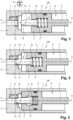
- a hydraulic cylinder 100 comprising a hollow cylinder 1 in which a piston 2 is mounted to slide along a longitudinal axis X, here the central axis of the cylinder 1.
- the cylinder is delimited on both sides by a first background (not visible here) crossed by a Solidaire rod 4 of the Piston 2, and a second bottom 3 visible here.
- the piston 2 delimits in the cylinder 1 a hydraulic extension chamber 5 and a hydraulic retraction chamber 6.
- the extension chamber is here connected to an expansion port P.
- the extension port P is connected to the extension chamber 5 by a first hydraulic conduit 7 of sufficiently large diameter to induce only minor pressure losses, and a second hydraulic conduit 8 of smaller diameter, deliberately forming a restriction for the passage of fluid.
- the piston 2 carries a finger 10 mounted sliding on the piston 2, here along the longitudinal axis against the action of a spring 11 which returns the finger towards a protruding position defined by the cooperation of a collar 16 extending projecting from an end portion of the finger 10 with a shoulder of a cavity 17 of the piston 2 receiving the spring 11 and said end portion of the finger 10.
- the first hydraulic conduit 7 comprises a seat 13 attached to the second bottom 3 and arranged opposite a conical end 14 of the finger 10.
- the finger 10, the spring 11, the seat 13, and the two hydraulic conduits 7, 8 together form the slowing down device, the operation of which is now detailed.
- the second hydraulic conduit 8 comprises a localized restriction of section so that the flow of fluid through the second hydraulic conduit 8 generates an increase in pressure in the expansion chamber 5 which contributes to slowing down the piston 2. It will be noted that such a flow occurs in turbulent regime.
- the orifice forming the localized section restriction which is here pierced in a thin plate mounted transversely in the hydraulic conduit 8 (said plate being symbolized only on the figure 1 ), will make it possible to increase the speed of the fluid and will generate turbulence, so that the resistance it generates is not very sensitive to the temperature of the fluid. It is essential that the plate in which the orifice is made has as thin a thickness as possible in order to obtain a flow described as “thin-walled”.
- Piston 2 then continues its stroke at reduced speed until the retracted position illustrated in Figure 3 , the fluid then flowing only through the second hydraulic conduit 8.
- the spring 11 guarantees the support of the end 14 of the finger 10 against the seat 13 so that the first hydraulic conduit 7 remains closed, while allowing retraction of finger 10 in piston 2.
- the calibration of the restriction organized by the second hydraulic conduit 8 can be obtained by drilling to a calibrated diameter of this second conduit, or by the use of a suitable restrictor. It is appropriate to allow easy evacuation of the fluid contained in the cavity 17 during the retraction of the finger 10, in order to avoid an increase in the pressure of the fluid in the cavity 17 which could cause a damping phenomenon resistant to the retraction of the finger 10. Likewise, it is appropriate to calibrate the stiffness of the spring 11 to ensure good support of the end 14 of the finger 10 on the seat 13, without you might as well generate a shock on contact which would prematurely wear out the seat 13.
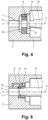
- the first hydraulic conduit 7 and the second hydraulic conduit 8 are made in a diaphragm 18 attached to the second bottom 3 of the cylinder 1.
- the seat 13 then consists simply of the edge delimiting the edge of the first hydraulic conduit 7 facing the end 14 of the finger 10.
- the precision machining production of the hydraulic conduits 7 and 8) can be carried out on a separate part, in a suitable material (for example bronze).
- a separate seat can be mounted on the diaphragm 18, in a similar manner to the cylinder of the figures 1 to 3 .
- the seat 13 is preceded by a ferrule 15, which can, as illustrated here, come from one piece with the seat 13, and which has the function of cooperating with the end 14 of the finger 10 to gradually reduce a passage section of the fluid through the first hydraulic conduit 7 before the end 14 comes to bear against the seat 13 and closes the conduit, in order to reduce or eliminate the pressure surges when closing the first hydraulic conduit 7.
- the ferrule 15 has a conical internal shape, but any other shape adapted to gradually close the first hydraulic conduit 7 can be used.
- the conical internal shape of the ferrule 15 has thus a circular passage section which decreases going towards the seat according to a progressive slope.
- the progressive slope allows a limitation of the speed of the piston, by creating progressive damping, and therefore the rise in pressure in the main extension chamber when the sliding piston arrives on the seat contained in the bearing.
- the flow of fluid thus decreases more gradually than in the absence of slope.
- the internal shape of the ferrule is dimensioned to also provide finger guidance. Indeed, the dimensional tolerances of several parts must be taken into account to ensure that the finger reaches the seat. Such a form makes it possible to reduce the machining uncertainties and the precision classes required for the machining of parts.
- the slope and the seat will preferably be made in the same room to allow better control of sliding, guiding and especially sealing.
- the fluid is forced to pass through the diaphragm, the hydraulic diameter of which is small, causing turbulent flow, as in a thin-walled orifice.
- the finger is here arranged on the piston to slide and retract along the longitudinal axis X
- the finger can be arranged so that it slides along any other axis parallel to the longitudinal axis X.
- the finger 10 has a conical end 14, this end can be given any shape capable of cooperating with the seat opposite to close the first hydraulic conduit 7.
- the section restriction can be machined into the body of the cylinder or the diaphragm, or be attached to them.
- the actuator of the invention is particularly interesting for use in aircraft landing gear, in particular for maneuvering this landing gear between the extended position and the retracted position of the landing gear.
- the actuator of the invention can also be used as an actuator to move a movable element relative to a fixed element of an aircraft, for example a movable flight surface, a fairing of a thrust reverser, etc.
- other applications of the cylinder of the invention are possible, for example as an actuator on ships or land motor vehicles.
Landscapes
- Engineering & Computer Science (AREA)
- Mechanical Engineering (AREA)
- General Engineering & Computer Science (AREA)
- Physics & Mathematics (AREA)
- Fluid Mechanics (AREA)
- Aviation & Aerospace Engineering (AREA)
- Actuator (AREA)
Claims (12)
- Hydraulikzylinder, umfassend einen Zylinder (1), in dem ein Kolben (2), der fest mit einer Stange (4) verbunden ist, auf dichte Weise verschiebbar gelagert ist, um in dem Zylinder eine hydraulische Extensionskammer (5) und eine hydraulische Retraktionskammer (6) zu begrenzen, die mit jeweiligen Öffnungen verbunden sind, wobei der Hydraulikzylinder Mittel zur Verlangsamung des Kolbens umfasst, wenn sich der Kolben einer rückgezogenen Position nähert, wobei die Verlangsamungsmittel erste und zweite Hydraulikleitungen (7, 8) umfassen, die sich zwischen der Extensionsöffnung und der Extensionskammer erstrecken, wobei die erste Hydraulikleitung einen Sitz (13) umfasst, während der Kolben einen einziehbaren Finger (10) trägt, der ein Ende (14) hat, das an dem Sitz zur Anlage kommt, um die erste Hydraulikleitung (7) zu verschließen, wenn sich der Kolben der zurückgezogenen Position nähert, derart, dass nur die zweite Hydraulikleitung (8) offen bleibt, während der Kolben seinen Hub in die zurückgezogene Position beendet, dadurch gekennzeichnet, dass dem Sitz (13) ein Ring (15) vorausgeht, der dazu bestimmt ist, mit dem Ende (14) des Fingers (10) zusammenzuwirken, bevor dieser an dem Sitz zur Anlage kommt, um fortschreitend einen Durchgangsquerschnitt der ersten Hydraulikleitung (7) zu verringern.
- Hydraulikzylinder nach Anspruch 1, bei dem der Ring (15) eine konische Innenform hat, die einen kreisförmigen Durchgangsquerschnitt hat, der in Richtung des Sitzes mit einer fortschreitenden Steigung abnimmt.
- Hydraulikzylinder nach Anspruch 1 oder 2, bei dem der Sitz (13) und der Ring (15) einstückig ausgebildet sind.
- Hydraulikzylinder nach einem der vorhergehenden Ansprüche, bei dem der Ring eine Innenform hat, die so bemessen ist, dass sie auch eine Führung des Fingers bildet.
- Hydraulikzylinder nach einem der vorhergehenden Ansprüche, bei dem sich die Hydraulikleitungen (7, 8) in einem Boden (3) des Zylinders (1) erstrecken.
- Hydraulikzylinder nach Anspruch 5, bei dem der Sitz (13) an dem Boden des Zylinders (1) befestigt ist.
- Hydraulikzylinder nach einem der Ansprüche 1 bis 4, bei dem die Hydraulikleitungen (7, 8) in einer Membran (18) ausgebildet sind, die in dem Zylinder (1) angebracht ist.
- Hydraulikzylinder nach einem der vorhergehenden Ansprüche, bei dem der Finger (10) an dem Kolben gemäß einer zentralen Achse (X) des Zylinders verschiebbar gelagert ist.
- Hydraulikzylinder nach einem der vorhergehenden Ansprüche, bei dem das Ende (14) des Fingers (10) konisch ist.
- Hydraulikzylinder nach einem der vorhergehenden Ansprüche, bei dem der Finger (10) entgegen der Wirkung von Rückstellmitteln (11), die den Finger in eine aus dem Kolben vorstehende Position drücken, einziehbar ist.
- Fahrwerk, umfassend einen Manövrierzylinder zum Manövrieren des Fahrwerks zwischen einer eingefahrenen Position und einer ausgefahrenen Position, dadurch gekennzeichnet, dass der Zylinder gemäß einem der vorhergehenden Ansprüche ist.
- Luftfahrzeug, umfassend ein Fahrwerk nach Anspruch 11.
Applications Claiming Priority (1)
| Application Number | Priority Date | Filing Date | Title |
|---|---|---|---|
| FR1904966A FR3096097B1 (fr) | 2019-05-13 | 2019-05-13 | Vérin hydraulique equipé d’un dispositif de ralentissement de fin de course |
Publications (2)
| Publication Number | Publication Date |
|---|---|
| EP3739221A1 EP3739221A1 (de) | 2020-11-18 |
| EP3739221B1 true EP3739221B1 (de) | 2023-09-13 |
Family
ID=67441470
Family Applications (1)
| Application Number | Title | Priority Date | Filing Date |
|---|---|---|---|
| EP20174231.9A Active EP3739221B1 (de) | 2019-05-13 | 2020-05-12 | Hydraulikzylinder, der mit einer vorrichtung zur verlangsamung am endanschlag ausgestattet ist |
Country Status (3)
| Country | Link |
|---|---|
| US (1) | US11268549B2 (de) |
| EP (1) | EP3739221B1 (de) |
| FR (1) | FR3096097B1 (de) |
Families Citing this family (3)
| Publication number | Priority date | Publication date | Assignee | Title |
|---|---|---|---|---|
| US20220228640A1 (en) * | 2019-05-31 | 2022-07-21 | Hydra Dyne Technology Inc. | Stroke cushioning in piston and cylinder devices |
| DE112022000736T5 (de) * | 2021-03-23 | 2023-11-23 | Caterpillar Inc. | Rückhalteanordnung für hydraulikzylinderstossdämpfung |
| US11319972B1 (en) * | 2021-05-11 | 2022-05-03 | Caterpillar Inc. | Hydraulic cylinder snubbing retention arrangement |
Citations (2)
| Publication number | Priority date | Publication date | Assignee | Title |
|---|---|---|---|---|
| US3999463A (en) * | 1975-02-27 | 1976-12-28 | Componetrol, Inc. | Fluid motor construction |
| US5692429A (en) * | 1994-10-18 | 1997-12-02 | Imi Norgren Gmbh | Fluid-powered cylinder |
Family Cites Families (7)
| Publication number | Priority date | Publication date | Assignee | Title |
|---|---|---|---|---|
| FR633581A (fr) * | 1926-06-16 | 1928-01-31 | Nat Pneumatic Co | Moteur à fluide sous pression |
| US2553810A (en) * | 1948-12-09 | 1951-05-22 | George W Houlsby Jr | Fluid control device |
| US3067726A (en) * | 1961-02-27 | 1962-12-11 | Int Basic Economy Corp | Cushioning structure for fluid power cylinders |
| GB1536417A (en) * | 1975-06-19 | 1978-12-20 | Emhart Ind | Cylinder and piston assemblies |
| US4138928A (en) * | 1977-02-11 | 1979-02-13 | Ware Machine Service Inc. | Fluid actuated apparatus |
| JP6649024B2 (ja) * | 2015-09-30 | 2020-02-19 | 住友精密工業株式会社 | 航空機の降着装置用油圧シリンダ |
| US10202988B2 (en) * | 2016-06-17 | 2019-02-12 | Deere & Company | Cushion mechanism for a hydraulic cylinder |
-
2019
- 2019-05-13 FR FR1904966A patent/FR3096097B1/fr active Active
-
2020
- 2020-05-12 EP EP20174231.9A patent/EP3739221B1/de active Active
- 2020-05-12 US US16/872,857 patent/US11268549B2/en active Active
Patent Citations (2)
| Publication number | Priority date | Publication date | Assignee | Title |
|---|---|---|---|---|
| US3999463A (en) * | 1975-02-27 | 1976-12-28 | Componetrol, Inc. | Fluid motor construction |
| US5692429A (en) * | 1994-10-18 | 1997-12-02 | Imi Norgren Gmbh | Fluid-powered cylinder |
Also Published As
| Publication number | Publication date |
|---|---|
| EP3739221A1 (de) | 2020-11-18 |
| FR3096097A1 (fr) | 2020-11-20 |
| US11268549B2 (en) | 2022-03-08 |
| FR3096097B1 (fr) | 2021-09-24 |
| US20200362887A1 (en) | 2020-11-19 |
Similar Documents
| Publication | Publication Date | Title |
|---|---|---|
| EP3739221B1 (de) | Hydraulikzylinder, der mit einer vorrichtung zur verlangsamung am endanschlag ausgestattet ist | |
| EP3121071B1 (de) | Reinigungsvorrichtung eines sensors für kraftfahrzeug | |
| EP2048408B1 (de) | Stoßdämpfer eines Fahrzeugs | |
| FR2591695A1 (fr) | Amortisseur de vibrations a deux tubes | |
| EP2964946B1 (de) | Düse mit variablem halsabschnitt für ein raumfahrtschubwerk mit einer mobilen nadel | |
| EP1636077A2 (de) | Servomotor mit verringertem totgang und solch einen servomotor umfassendes bremssystem | |
| FR2623255A1 (fr) | Maitre-cylindre d'embrayage | |
| CA2610063C (fr) | Organe telescopique a butee interne effacable | |
| EP0066795B1 (de) | Schnell schliessendes Ventil für komprimierbares Fluidum | |
| FR2538468A1 (fr) | Verin-amortisseur hydraulique notamment pour equipement sous-marin | |
| EP2505852B1 (de) | Hydraulisches stellglied mit automatischem entlüftungssystem am endanschlag | |
| FR3010748A1 (fr) | Actionneur telescopique. | |
| FR3071299B1 (fr) | Vanne thermostatique pour vehicule automobile | |
| CA2566241C (fr) | Dispositif d'amortisseur a deceleration asservie, et son application a l'amortissement de la colonne de direction escamotable d'un vehicule automobile | |
| EP3724740B1 (de) | Thermostatventil | |
| EP3017210B1 (de) | Bremsvorrichtung mit einem kolben mit vollständiger rückstossfunktion | |
| EP2964973A1 (de) | Selbstverriegelnder zylinder für eine tür eines kraftfahrzeugs | |
| FR2738885A1 (fr) | Verin a pression fluide d'une chambre intermediaire coulissante | |
| FR2552514A1 (fr) | Amortisseur du type fluidique | |
| FR3056517A1 (fr) | Dispositif de nettoyage, destine a projeter au moins un fluide vers une surface a nettoyer d'un vehicule automobile, tel qu'une surface optique d'un capteur d'un systeme de detection optique | |
| FR2957646A1 (fr) | Dispositif d'amortissement en fin de course du deplacement d'un corps | |
| EP1102938B1 (de) | Kolben und vorrichtung zur hydraulischen steuerung einer kraftfahrzeugkupplung mitels eines derartigen kolbens | |
| FR2989430A1 (fr) | Valve de limitation de pression a double seuil | |
| FR2876757A1 (fr) | Verin, de preference double effet, a amortisseur de fin de course | |
| EP3477415B1 (de) | Thermostatventil |
Legal Events
| Date | Code | Title | Description |
|---|---|---|---|
| PUAI | Public reference made under article 153(3) epc to a published international application that has entered the european phase |
Free format text: ORIGINAL CODE: 0009012 |
|
| STAA | Information on the status of an ep patent application or granted ep patent |
Free format text: STATUS: THE APPLICATION HAS BEEN PUBLISHED |
|
| AK | Designated contracting states |
Kind code of ref document: A1 Designated state(s): AL AT BE BG CH CY CZ DE DK EE ES FI FR GB GR HR HU IE IS IT LI LT LU LV MC MK MT NL NO PL PT RO RS SE SI SK SM TR |
|
| AX | Request for extension of the european patent |
Extension state: BA ME |
|
| STAA | Information on the status of an ep patent application or granted ep patent |
Free format text: STATUS: REQUEST FOR EXAMINATION WAS MADE |
|
| 17P | Request for examination filed |
Effective date: 20210421 |
|
| RBV | Designated contracting states (corrected) |
Designated state(s): AL AT BE BG CH CY CZ DE DK EE ES FI FR GB GR HR HU IE IS IT LI LT LU LV MC MK MT NL NO PL PT RO RS SE SI SK SM TR |
|
| STAA | Information on the status of an ep patent application or granted ep patent |
Free format text: STATUS: EXAMINATION IS IN PROGRESS |
|
| 17Q | First examination report despatched |
Effective date: 20220217 |
|
| GRAP | Despatch of communication of intention to grant a patent |
Free format text: ORIGINAL CODE: EPIDOSNIGR1 |
|
| STAA | Information on the status of an ep patent application or granted ep patent |
Free format text: STATUS: GRANT OF PATENT IS INTENDED |
|
| INTG | Intention to grant announced |
Effective date: 20230412 |
|
| GRAS | Grant fee paid |
Free format text: ORIGINAL CODE: EPIDOSNIGR3 |
|
| GRAA | (expected) grant |
Free format text: ORIGINAL CODE: 0009210 |
|
| STAA | Information on the status of an ep patent application or granted ep patent |
Free format text: STATUS: THE PATENT HAS BEEN GRANTED |
|
| AK | Designated contracting states |
Kind code of ref document: B1 Designated state(s): AL AT BE BG CH CY CZ DE DK EE ES FI FR GB GR HR HU IE IS IT LI LT LU LV MC MK MT NL NO PL PT RO RS SE SI SK SM TR |
|
| REG | Reference to a national code |
Ref country code: CH Ref legal event code: EP |
|
| REG | Reference to a national code |
Ref country code: DE Ref legal event code: R096 Ref document number: 602020017507 Country of ref document: DE |
|
| REG | Reference to a national code |
Ref country code: IE Ref legal event code: FG4D Free format text: LANGUAGE OF EP DOCUMENT: FRENCH |
|
| REG | Reference to a national code |
Ref country code: LT Ref legal event code: MG9D |
|
| REG | Reference to a national code |
Ref country code: NL Ref legal event code: MP Effective date: 20230913 |
|
| PG25 | Lapsed in a contracting state [announced via postgrant information from national office to epo] |
Ref country code: GR Free format text: LAPSE BECAUSE OF FAILURE TO SUBMIT A TRANSLATION OF THE DESCRIPTION OR TO PAY THE FEE WITHIN THE PRESCRIBED TIME-LIMIT Effective date: 20231214 |
|
| PG25 | Lapsed in a contracting state [announced via postgrant information from national office to epo] |
Ref country code: SE Free format text: LAPSE BECAUSE OF FAILURE TO SUBMIT A TRANSLATION OF THE DESCRIPTION OR TO PAY THE FEE WITHIN THE PRESCRIBED TIME-LIMIT Effective date: 20230913 Ref country code: RS Free format text: LAPSE BECAUSE OF FAILURE TO SUBMIT A TRANSLATION OF THE DESCRIPTION OR TO PAY THE FEE WITHIN THE PRESCRIBED TIME-LIMIT Effective date: 20230913 Ref country code: NO Free format text: LAPSE BECAUSE OF FAILURE TO SUBMIT A TRANSLATION OF THE DESCRIPTION OR TO PAY THE FEE WITHIN THE PRESCRIBED TIME-LIMIT Effective date: 20231213 Ref country code: LV Free format text: LAPSE BECAUSE OF FAILURE TO SUBMIT A TRANSLATION OF THE DESCRIPTION OR TO PAY THE FEE WITHIN THE PRESCRIBED TIME-LIMIT Effective date: 20230913 Ref country code: LT Free format text: LAPSE BECAUSE OF FAILURE TO SUBMIT A TRANSLATION OF THE DESCRIPTION OR TO PAY THE FEE WITHIN THE PRESCRIBED TIME-LIMIT Effective date: 20230913 Ref country code: HR Free format text: LAPSE BECAUSE OF FAILURE TO SUBMIT A TRANSLATION OF THE DESCRIPTION OR TO PAY THE FEE WITHIN THE PRESCRIBED TIME-LIMIT Effective date: 20230913 Ref country code: GR Free format text: LAPSE BECAUSE OF FAILURE TO SUBMIT A TRANSLATION OF THE DESCRIPTION OR TO PAY THE FEE WITHIN THE PRESCRIBED TIME-LIMIT Effective date: 20231214 Ref country code: FI Free format text: LAPSE BECAUSE OF FAILURE TO SUBMIT A TRANSLATION OF THE DESCRIPTION OR TO PAY THE FEE WITHIN THE PRESCRIBED TIME-LIMIT Effective date: 20230913 |
|
| REG | Reference to a national code |
Ref country code: AT Ref legal event code: MK05 Ref document number: 1611563 Country of ref document: AT Kind code of ref document: T Effective date: 20230913 |
|
| PG25 | Lapsed in a contracting state [announced via postgrant information from national office to epo] |
Ref country code: NL Free format text: LAPSE BECAUSE OF FAILURE TO SUBMIT A TRANSLATION OF THE DESCRIPTION OR TO PAY THE FEE WITHIN THE PRESCRIBED TIME-LIMIT Effective date: 20230913 |
|
| PG25 | Lapsed in a contracting state [announced via postgrant information from national office to epo] |
Ref country code: IS Free format text: LAPSE BECAUSE OF FAILURE TO SUBMIT A TRANSLATION OF THE DESCRIPTION OR TO PAY THE FEE WITHIN THE PRESCRIBED TIME-LIMIT Effective date: 20240113 |
|
| PG25 | Lapsed in a contracting state [announced via postgrant information from national office to epo] |
Ref country code: AT Free format text: LAPSE BECAUSE OF FAILURE TO SUBMIT A TRANSLATION OF THE DESCRIPTION OR TO PAY THE FEE WITHIN THE PRESCRIBED TIME-LIMIT Effective date: 20230913 |
|
| PG25 | Lapsed in a contracting state [announced via postgrant information from national office to epo] |
Ref country code: ES Free format text: LAPSE BECAUSE OF FAILURE TO SUBMIT A TRANSLATION OF THE DESCRIPTION OR TO PAY THE FEE WITHIN THE PRESCRIBED TIME-LIMIT Effective date: 20230913 |
|
| PG25 | Lapsed in a contracting state [announced via postgrant information from national office to epo] |
Ref country code: SM Free format text: LAPSE BECAUSE OF FAILURE TO SUBMIT A TRANSLATION OF THE DESCRIPTION OR TO PAY THE FEE WITHIN THE PRESCRIBED TIME-LIMIT Effective date: 20230913 Ref country code: RO Free format text: LAPSE BECAUSE OF FAILURE TO SUBMIT A TRANSLATION OF THE DESCRIPTION OR TO PAY THE FEE WITHIN THE PRESCRIBED TIME-LIMIT Effective date: 20230913 Ref country code: IS Free format text: LAPSE BECAUSE OF FAILURE TO SUBMIT A TRANSLATION OF THE DESCRIPTION OR TO PAY THE FEE WITHIN THE PRESCRIBED TIME-LIMIT Effective date: 20240113 Ref country code: ES Free format text: LAPSE BECAUSE OF FAILURE TO SUBMIT A TRANSLATION OF THE DESCRIPTION OR TO PAY THE FEE WITHIN THE PRESCRIBED TIME-LIMIT Effective date: 20230913 Ref country code: EE Free format text: LAPSE BECAUSE OF FAILURE TO SUBMIT A TRANSLATION OF THE DESCRIPTION OR TO PAY THE FEE WITHIN THE PRESCRIBED TIME-LIMIT Effective date: 20230913 Ref country code: CZ Free format text: LAPSE BECAUSE OF FAILURE TO SUBMIT A TRANSLATION OF THE DESCRIPTION OR TO PAY THE FEE WITHIN THE PRESCRIBED TIME-LIMIT Effective date: 20230913 Ref country code: AT Free format text: LAPSE BECAUSE OF FAILURE TO SUBMIT A TRANSLATION OF THE DESCRIPTION OR TO PAY THE FEE WITHIN THE PRESCRIBED TIME-LIMIT Effective date: 20230913 Ref country code: PT Free format text: LAPSE BECAUSE OF FAILURE TO SUBMIT A TRANSLATION OF THE DESCRIPTION OR TO PAY THE FEE WITHIN THE PRESCRIBED TIME-LIMIT Effective date: 20240115 Ref country code: SK Free format text: LAPSE BECAUSE OF FAILURE TO SUBMIT A TRANSLATION OF THE DESCRIPTION OR TO PAY THE FEE WITHIN THE PRESCRIBED TIME-LIMIT Effective date: 20230913 |
|
| PG25 | Lapsed in a contracting state [announced via postgrant information from national office to epo] |
Ref country code: PL Free format text: LAPSE BECAUSE OF FAILURE TO SUBMIT A TRANSLATION OF THE DESCRIPTION OR TO PAY THE FEE WITHIN THE PRESCRIBED TIME-LIMIT Effective date: 20230913 Ref country code: IT Free format text: LAPSE BECAUSE OF FAILURE TO SUBMIT A TRANSLATION OF THE DESCRIPTION OR TO PAY THE FEE WITHIN THE PRESCRIBED TIME-LIMIT Effective date: 20230913 |
|
| REG | Reference to a national code |
Ref country code: DE Ref legal event code: R097 Ref document number: 602020017507 Country of ref document: DE |
|
| PG25 | Lapsed in a contracting state [announced via postgrant information from national office to epo] |
Ref country code: DK Free format text: LAPSE BECAUSE OF FAILURE TO SUBMIT A TRANSLATION OF THE DESCRIPTION OR TO PAY THE FEE WITHIN THE PRESCRIBED TIME-LIMIT Effective date: 20230913 |
|
| PLBE | No opposition filed within time limit |
Free format text: ORIGINAL CODE: 0009261 |
|
| STAA | Information on the status of an ep patent application or granted ep patent |
Free format text: STATUS: NO OPPOSITION FILED WITHIN TIME LIMIT |
|
| PG25 | Lapsed in a contracting state [announced via postgrant information from national office to epo] |
Ref country code: DK Free format text: LAPSE BECAUSE OF FAILURE TO SUBMIT A TRANSLATION OF THE DESCRIPTION OR TO PAY THE FEE WITHIN THE PRESCRIBED TIME-LIMIT Effective date: 20230913 |
|
| 26N | No opposition filed |
Effective date: 20240614 |
|
| PG25 | Lapsed in a contracting state [announced via postgrant information from national office to epo] |
Ref country code: SI Free format text: LAPSE BECAUSE OF FAILURE TO SUBMIT A TRANSLATION OF THE DESCRIPTION OR TO PAY THE FEE WITHIN THE PRESCRIBED TIME-LIMIT Effective date: 20230913 |
|
| PG25 | Lapsed in a contracting state [announced via postgrant information from national office to epo] |
Ref country code: SI Free format text: LAPSE BECAUSE OF FAILURE TO SUBMIT A TRANSLATION OF THE DESCRIPTION OR TO PAY THE FEE WITHIN THE PRESCRIBED TIME-LIMIT Effective date: 20230913 |
|
| PG25 | Lapsed in a contracting state [announced via postgrant information from national office to epo] |
Ref country code: BG Free format text: LAPSE BECAUSE OF FAILURE TO SUBMIT A TRANSLATION OF THE DESCRIPTION OR TO PAY THE FEE WITHIN THE PRESCRIBED TIME-LIMIT Effective date: 20230913 |
|
| PG25 | Lapsed in a contracting state [announced via postgrant information from national office to epo] |
Ref country code: BG Free format text: LAPSE BECAUSE OF FAILURE TO SUBMIT A TRANSLATION OF THE DESCRIPTION OR TO PAY THE FEE WITHIN THE PRESCRIBED TIME-LIMIT Effective date: 20230913 |
|
| REG | Reference to a national code |
Ref country code: CH Ref legal event code: PL |
|
| PG25 | Lapsed in a contracting state [announced via postgrant information from national office to epo] |
Ref country code: MC Free format text: LAPSE BECAUSE OF FAILURE TO SUBMIT A TRANSLATION OF THE DESCRIPTION OR TO PAY THE FEE WITHIN THE PRESCRIBED TIME-LIMIT Effective date: 20230913 |
|
| PG25 | Lapsed in a contracting state [announced via postgrant information from national office to epo] |
Ref country code: LU Free format text: LAPSE BECAUSE OF NON-PAYMENT OF DUE FEES Effective date: 20240512 |
|
| PG25 | Lapsed in a contracting state [announced via postgrant information from national office to epo] |
Ref country code: MC Free format text: LAPSE BECAUSE OF FAILURE TO SUBMIT A TRANSLATION OF THE DESCRIPTION OR TO PAY THE FEE WITHIN THE PRESCRIBED TIME-LIMIT Effective date: 20230913 Ref country code: LU Free format text: LAPSE BECAUSE OF NON-PAYMENT OF DUE FEES Effective date: 20240512 Ref country code: CH Free format text: LAPSE BECAUSE OF NON-PAYMENT OF DUE FEES Effective date: 20240531 |
|
| REG | Reference to a national code |
Ref country code: BE Ref legal event code: MM Effective date: 20240531 |
|
| PG25 | Lapsed in a contracting state [announced via postgrant information from national office to epo] |
Ref country code: IE Free format text: LAPSE BECAUSE OF NON-PAYMENT OF DUE FEES Effective date: 20240512 |
|
| PG25 | Lapsed in a contracting state [announced via postgrant information from national office to epo] |
Ref country code: BE Free format text: LAPSE BECAUSE OF NON-PAYMENT OF DUE FEES Effective date: 20240531 |
|
| PGFP | Annual fee paid to national office [announced via postgrant information from national office to epo] |
Ref country code: DE Payment date: 20250519 Year of fee payment: 6 |
|
| PGFP | Annual fee paid to national office [announced via postgrant information from national office to epo] |
Ref country code: GB Payment date: 20250527 Year of fee payment: 6 |
|
| PGFP | Annual fee paid to national office [announced via postgrant information from national office to epo] |
Ref country code: FR Payment date: 20250526 Year of fee payment: 6 |
|
| PG25 | Lapsed in a contracting state [announced via postgrant information from national office to epo] |
Ref country code: CY Free format text: LAPSE BECAUSE OF FAILURE TO SUBMIT A TRANSLATION OF THE DESCRIPTION OR TO PAY THE FEE WITHIN THE PRESCRIBED TIME-LIMIT; INVALID AB INITIO Effective date: 20200512 |
|
| PG25 | Lapsed in a contracting state [announced via postgrant information from national office to epo] |
Ref country code: HU Free format text: LAPSE BECAUSE OF FAILURE TO SUBMIT A TRANSLATION OF THE DESCRIPTION OR TO PAY THE FEE WITHIN THE PRESCRIBED TIME-LIMIT; INVALID AB INITIO Effective date: 20200512 |