EP3738835A1 - Retention system and method for an electrical plug outlet inside a vehicle - Google Patents
Retention system and method for an electrical plug outlet inside a vehicle Download PDFInfo
- Publication number
- EP3738835A1 EP3738835A1 EP20173366.4A EP20173366A EP3738835A1 EP 3738835 A1 EP3738835 A1 EP 3738835A1 EP 20173366 A EP20173366 A EP 20173366A EP 3738835 A1 EP3738835 A1 EP 3738835A1
- Authority
- EP
- European Patent Office
- Prior art keywords
- reinforcing plate
- vehicle
- tab
- support plate
- protrusion
- Prior art date
- Legal status (The legal status is an assumption and is not a legal conclusion. Google has not performed a legal analysis and makes no representation as to the accuracy of the status listed.)
- Granted
Links
Images






Classifications
-
- B—PERFORMING OPERATIONS; TRANSPORTING
- B60—VEHICLES IN GENERAL
- B60R—VEHICLES, VEHICLE FITTINGS, OR VEHICLE PARTS, NOT OTHERWISE PROVIDED FOR
- B60R16/00—Electric or fluid circuits specially adapted for vehicles and not otherwise provided for; Arrangement of elements of electric or fluid circuits specially adapted for vehicles and not otherwise provided for
- B60R16/02—Electric or fluid circuits specially adapted for vehicles and not otherwise provided for; Arrangement of elements of electric or fluid circuits specially adapted for vehicles and not otherwise provided for electric constitutive elements
-
- H—ELECTRICITY
- H02—GENERATION; CONVERSION OR DISTRIBUTION OF ELECTRIC POWER
- H02K—DYNAMO-ELECTRIC MACHINES
- H02K5/00—Casings; Enclosures; Supports
Definitions
- the object of the present invention is, according to a first aspect, a retention system for an electrical plug outlet in the interior of a vehicle, which significantly reduces the complexity of the assembly operations of the electrical plug outlet inside the vehicle.
- a second aspect of the present invention relates to an inner cladding of a vehicle, which incorporates the retention system of the first aspect of the invention, particularly applicable to motor vehicle boots.
- a third aspect of the present invention relates to a retention method for an electrical plug outlet in the interior of a vehicle which is especially applicable to the scope of the industry dedicated to the design, manufacture and marketing of motor vehicles.
- carpet plate or sheet or inner cladding of the boot
- Said carpet part is not firmly adhered to the chassis or body of the vehicle.
- the carpet part has a lower mechanical resistance than that of the structural elements of the chassis or body of the vehicle.
- the mechanical resistance thereof is sufficient to withstand the type of stress to which it is subjected by contact with luggage items that are arranged and housed inside the boot without deforming.
- the carpet part has low pressure resistance and low fatigue resistance.
- the insertion and removal movements of the pin are typically considered to entail an average force of 60 N, applied to a relatively small surface area, such as that of the plug pin.
- the present invention relates to a retention system and method for an electrical plug outlet in the interior of a vehicle, which has a simple configuration and great simplicity and versatility in the installation thereof and in accessibility for maintenance, while also providing great stability and mechanical resistance against the stresses required by an element of this type.
- the retention system for an electrical plug outlet inside a vehicle object of the present invention, incorporates:
- the reinforcing plate comprises a closed curve or closed polygon geometry such that it defines an opening to receive the electrical plug outlet to be housed in the plug socket casing.
- the reinforcing plate and the support plate comprise fixing means for fixing the reinforcing plate to a flange of the plug socket casing.
- a retention system that, while being fixed to the cladding part, transmits the pressure exerted by the plug pin directly to the vehicle body, making it so that the cladding part is not the part that has to support the demanding stresses in terms of pressure and fatigue of the pin on the electrical plug outlet. This is accomplished by anchoring the support plate to the body of the vehicle, and by fixing the reinforcing plate to the support plate.
- the support plate defines a second housing configured to receive a transformer.
- This transformer is configured to convert a direct current delivered by a battery of the vehicle into an alternating current.
- the fixing means for fixing the reinforcing plate to the support plate comprise at least one tab located on a perimeter edge of the reinforcing plate defining the opening.
- the aforementioned fixing means comprise at least one protrusion located on the edge of the plug socket casing and in correspondence with the at least one tab of the reinforcing plate. The at least one protrusion is configured to be inserted into the at least one tab, thus preventing relative transverse displacement between the at least one protrusion and the at least one tab, with the reinforcing plate being in the assembled position thereof.
- transverse displacement a direction transverse or perpendicular to the insertion direction of the protrusion in the tab or, in other words, a direction parallel to the insertion/removal direction of the plug pin in the electrical plug outlet is being referred to.
- the at least one tab comprises a proximal end substantially parallel to the perimeter edge of the reinforcing plate, being configured to house the at least one protrusion between said proximal end and the perimeter edge of the reinforcing plate.
- the thickness of the at least one protrusion is substantially equal to the space defined between the proximal end of the tab and the perimeter edge of the reinforcing plate.
- the at least one tab comprises a distal end arranged at a distance from the perimeter edge of the reinforcing plate greater than the distance from the proximal end.
- the distal end is configured to guide the at least one protrusion during the operation of assembling the reinforcing plate on the support plate.
- the at least one tab comprises a ramp-like structure between the proximal end and the distal end, such that the distance between the tab and the perimeter edge of the reinforcing plate increases continuously between said proximal end and said distal end.
- the at least one tab comprises a recess and the at least one protrusion comprises a projection, said projection being configured to be retained by the recess of the tab, thus preventing relative longitudinal displacement between the at least one protrusion and the at least one tab.
- the projection is preferably present on the lower protrusions and the recesses are preferably present on the lower tabs.
- the plug socket casing comprises retaining means configured to retain the electrical plug outlet in the first housing of the support plate.
- these retaining means comprise a staple or clip.
- the support plate is made of plastic material.
- the anchoring means of the support plate to the body of the vehicle comprise screws and nuts.
- the present invention also relates to an inner cladding of a vehicle which incorporates a retention system for an electrical plug outlet as described above.
- This cladding can be plastic or a type of carpet.
- the present invention also relates to a retention method for an electrical plug outlet inside a vehicle, comprising the steps of:
- the use of the support plate allows the cladding, which incorporates the reinforcing plate, to be mechanically attached to the body of the vehicle. This will provide the necessary rigidity to the assembly to transmit the tensile stresses supported by the electrical plug outlet to the body.
- a simple process for assembling the retention system is sought. It must be taken into account that, once the cladding is fixed to the body, there is no possibility of accessing the unseen face of said cladding, therefore it is not possible to manipulate or make fixations on said unseen face of the cladding.
- the present invention seeks to take advantage of the operation of manipulating and fixing the cladding to the body to additionally fix the reinforcing plate to the support plate.
- the specific joining means of the inner cladding of the vehicle to the body are independent of the retention system for the electrical plug outlet object of the present invention.
- the retention method comprises a step of housing a transformer in a second housing defined by the support plate.
- This transformer is configured to convert a direct current delivered by a battery of the vehicle into an alternating current.
- the step of fixing the reinforcing plate to the inner cladding of the vehicle is carried out by means of a welding process. Alternatively, this can be done by bi-injection.
- the fixing means (to mechanically attach the reinforcing plate to the support plate) comprise at least one tab located on a perimeter edge of the reinforcing plate.
- These fixing means further comprise at least one protrusion located on one edge of the plug socket casing.
- the at least one tab comprises a proximal end substantially parallel to the perimeter edge of the reinforcing plate, and the at least one tab comprises a distal end arranged at a distance from the perimeter edge of the reinforcing plate greater than the distance from the proximal end.
- the step of mechanically attaching the reinforcing plate to the support plate comprises:
- the retention method further comprises the steps of:
- the present invention relates, as mentioned above, to a retention system for an electrical plug outlet (102) in the interior of a vehicle.
- the retention system for an electrical plug outlet comprises (see Figure 1 and Figure 2 ) a support plate (100), configured to support a transformer (101).
- This transformer (101) is in charge of transforming the direct current (DC) at the output of the vehicle battery into an alternating current (AC) suitable for applications and devices to be plugged into the electrical plug outlet (102).
- DC direct current
- AC alternating current
- said alternating current equals 230 V.
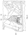
- the support plate (100) is configured (see Figure 3 ) to be anchored to the body (400) or chassis of the vehicle. This anchoring of the support plate (100) is carried out by means of anchoring means (500) (typically screws and nuts).
- the function of the support plate (100) is to provide cavities to retain both the electrical plug outlet (102) and the transformer (101). Furthermore, it makes it possible to withstand the tensile stresses supported by the electrical plug outlet (102) in the operations of plugging and unplugging a connector to said electrical plug outlet (102) and transmitting said stresses to the body (400) of the vehicle.
- the support plate (100) comprises a plug socket casing (200) that defines a first housing (103) configured to receive the electrical plug outlet (102).
- the support plate (100) defines a second housing (105) to house the transformer (101).
- the retention system for the electrical plug outlet (102) comprises a reinforcing plate (300), configured to be fixed to the support plate (100), on the flange (104) of the plug socket casing (200).
- the reinforcing plate (300) is in turn configured to be adhered, fixed or welded to the inner carpet or cladding part (600) of the boot of a vehicle (see Figure 4 ).
- the support plate (100), the transformer (101) and the fixings that enable the support plate (100) to be joined to both the body (400) and the reinforcing plate (300) are located on said unseen surface. Therefore, an operator cannot access or manipulate said components once the cladding (600) has been fixed to the body (400).
- the fixing of the support plate (100) with the reinforcing plate (300) occurs simultaneously with the operation of centring and assembling the cladding (600) on said body (400).
- the reinforcing plate (300) comprises (see Figure 5 and Figure 6 ), in correspondence with a perimeter edge (302), tabs (301) (typically upper tabs (301a) and lower tabs (301b)), configured to fix the reinforcing plate (300) to the support plate (100), by means of protrusions (201) (typically upper protrusions (201a) and lower protrusions (201b)) existing on the flange (104) of the plug socket casing (200), where said protrusions (201) are configured to be introduced into the tabs (301) of said reinforcing plate (300).
- the flanges (301) are located on a surface of the perimeter edge (302) close to the support plate (100), the reinforcing plate (300) being in an assembled position with respect to the support plate (100).
- the protrusions (201) are located on a surface of the plug socket casing (200) close to the reinforcing plate (300), the reinforcing plate (300) being in an assembled position with respect to the support plate (100).
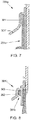
- the tabs (301) have a funnel or ramp-like shape, with a proximal end (301') closest to the perimeter edge (302) of the reinforcing plate (300) and a distal end (301'") furthest from said perimeter edge (302), to ensure that the protrusion (201) is introduced into the tab (301) and to guide said protrusion (201) to a retaining position of the reinforcing plate (300) in the support plate (100).
- the protrusion (201) has at least one support surface with the perimeter edge (302) of the reinforcing plate (300), wherein said support surface extends in the longitudinal direction, in other words, in one direction substantially perpendicular to the insertion/removal efforts of the plug pin in the electrical plug outlet (102).
- the protrusion (201) is arranged between the tab (301) and the perimeter edge (302) in said direction substantially perpendicular to the insertion/removal efforts of the plug pin in the electrical plug outlet (102), the reinforcing plate (300) being assembled on the support plate (100).
- the protrusion (201) forms a flat surface which, when inserted into the tab (301) of the reinforcing plate, is trapped between two flat surfaces of the tab (301), typically between the proximal end (301') and an inner area of the tab (301), although it can also be trapped between the proximal end (301') of the tab (301) and the perimeter edge (302) of the reinforcing plate (300).
- the lower flanges (301b) comprise a recess (303) to couple a projection (202) of the protrusion (201) of the support plate (100), so that a retention in the vertical direction of the reinforcing plate (300) on the support plate (100) is also generated.
- the electrical plug outlet (102) is introduced into the first housing (103) defined by the plug socket casing (200) of the support plate (100), and is retained by the support plate (100) in said plug socket casing (200), by means of retaining means (700), which can be materialised in a clip or a fixing clamp (see Figure 9 and Figure 10 ).
- the reinforcing plate (300) and the support plate (100) are joined by means of a linear movement or translation of the cladding part (600) (carpet part) with respect to the support plate (100) (movement from top to bottom, as shown in the figures).
- the electrical plug outlet (102) is preferably equipped with an aesthetic cover (800) (see Figure 2 ).
Landscapes
- Engineering & Computer Science (AREA)
- Mechanical Engineering (AREA)
- Power Engineering (AREA)
- Connector Housings Or Holding Contact Members (AREA)
Abstract
Description
- The object of the present invention is, according to a first aspect, a retention system for an electrical plug outlet in the interior of a vehicle, which significantly reduces the complexity of the assembly operations of the electrical plug outlet inside the vehicle.
- A second aspect of the present invention relates to an inner cladding of a vehicle, which incorporates the retention system of the first aspect of the invention, particularly applicable to motor vehicle boots.
- A third aspect of the present invention relates to a retention method for an electrical plug outlet in the interior of a vehicle which is especially applicable to the scope of the industry dedicated to the design, manufacture and marketing of motor vehicles.
- Nowadays, car boots are usually covered with a carpet plate or sheet (or inner cladding of the boot), providing higher quality surface finish to the inside of the boot on the entire visible surface thereof. Said carpet part is not firmly adhered to the chassis or body of the vehicle. Likewise, the carpet part has a lower mechanical resistance than that of the structural elements of the chassis or body of the vehicle. However, since the carpet part is supported on the chassis, the mechanical resistance thereof is sufficient to withstand the type of stress to which it is subjected by contact with luggage items that are arranged and housed inside the boot without deforming.
- There are currently vehicles that incorporate electrical outlets, not only in the driver and passenger compartment, but also in the boot. These electrical outlets enable household appliances to be connected. This feature is useful, especially in situations where once the vehicle is parked, it is going to remain in proximity to the same and electrical devices that need to be connected to an electrical outlet are to be used. On the other hand, electrical outlets can also be used with the vehicle in motion or parked to charge an electric battery of a micro-mobility vehicle, such as an electric scooter.
- As already introduced, the carpet part has low pressure resistance and low fatigue resistance. The insertion and removal movements of the pin are typically considered to entail an average force of 60 N, applied to a relatively small surface area, such as that of the plug pin.
- Thus, given the high stresses that a plug requires in terms of pressure exerted by the plug pin and fatigue due to continuous insertions and removals over time, the provisions of electrical outlets in boots currently require complex installations that involve, in vehicles with an electrical outlet in the boot, a complete redesign of the carpet part that increases the cost, weight and rigidity thereof. In some solutions proposed in the state of the art, the provision of an electrical outlet in the boot of a vehicle involves welding the support of the electrical outlet assembly to the chassis of the vehicle. This arrangement makes the manufacture of the vehicle more expensive, and hinders possible maintenance tasks of said electrical outlet.
- In order to solve the aforementioned drawbacks, the present invention relates to a retention system and method for an electrical plug outlet in the interior of a vehicle, which has a simple configuration and great simplicity and versatility in the installation thereof and in accessibility for maintenance, while also providing great stability and mechanical resistance against the stresses required by an element of this type.
- The retention system for an electrical plug outlet inside a vehicle, object of the present invention, incorporates:
- a support plate configured to be anchored to a body of a vehicle by means of anchoring means; wherein the support plate comprises a plug socket casing defining a first housing configured to receive the electrical plug outlet;
- a reinforcing plate, configured to be mechanically attached, in an assembled position, to the support plate and configured to be fixed to a cladding part inside the vehicle.
- The reinforcing plate comprises a closed curve or closed polygon geometry such that it defines an opening to receive the electrical plug outlet to be housed in the plug socket casing. Likewise, the reinforcing plate and the support plate comprise fixing means for fixing the reinforcing plate to a flange of the plug socket casing.
- Given the above features, a retention system is provided that, while being fixed to the cladding part, transmits the pressure exerted by the plug pin directly to the vehicle body, making it so that the cladding part is not the part that has to support the demanding stresses in terms of pressure and fatigue of the pin on the electrical plug outlet. This is accomplished by anchoring the support plate to the body of the vehicle, and by fixing the reinforcing plate to the support plate.
- Preferably, the support plate defines a second housing configured to receive a transformer. This transformer is configured to convert a direct current delivered by a battery of the vehicle into an alternating current.
- According to a preferred embodiment of the retention system, the fixing means for fixing the reinforcing plate to the support plate comprise at least one tab located on a perimeter edge of the reinforcing plate defining the opening. Similarly, the aforementioned fixing means comprise at least one protrusion located on the edge of the plug socket casing and in correspondence with the at least one tab of the reinforcing plate. The at least one protrusion is configured to be inserted into the at least one tab, thus preventing relative transverse displacement between the at least one protrusion and the at least one tab, with the reinforcing plate being in the assembled position thereof.
- When "transverse displacement" is mentioned, a direction transverse or perpendicular to the insertion direction of the protrusion in the tab or, in other words, a direction parallel to the insertion/removal direction of the plug pin in the electrical plug outlet is being referred to.
- According to a possible embodiment of the retention system, the at least one tab comprises a proximal end substantially parallel to the perimeter edge of the reinforcing plate, being configured to house the at least one protrusion between said proximal end and the perimeter edge of the reinforcing plate.
- Thus, preferably, the thickness of the at least one protrusion is substantially equal to the space defined between the proximal end of the tab and the perimeter edge of the reinforcing plate.
- Likewise, according to a possible embodiment, the at least one tab comprises a distal end arranged at a distance from the perimeter edge of the reinforcing plate greater than the distance from the proximal end. Thus, the distal end is configured to guide the at least one protrusion during the operation of assembling the reinforcing plate on the support plate.
- Thus, preferably, the at least one tab comprises a ramp-like structure between the proximal end and the distal end, such that the distance between the tab and the perimeter edge of the reinforcing plate increases continuously between said proximal end and said distal end.
- In this way, the assembly of the reinforcing plate on the support plate is facilitated, since when the reinforcing plate is brought closer to the support plate, each protrusion will be placed without too much difficulty between the distal end of the tab and the perimeter edge of the reinforcing plate, and a simple movement in the longitudinal direction (vertical direction or direction perpendicular to the insertion/removal direction of the plug pin) will suffice for the entire protrusion to be perfectly inserted in the space between the tab and the perimeter edge of the reinforcing plate.
- According to a possible embodiment, the at least one tab comprises a recess and the at least one protrusion comprises a projection, said projection being configured to be retained by the recess of the tab, thus preventing relative longitudinal displacement between the at least one protrusion and the at least one tab.
- In the case that the edge of the plug socket casing has upper and lower protrusions, and the perimeter edge of the reinforcing plate has upper and lower tabs, the projection is preferably present on the lower protrusions and the recesses are preferably present on the lower tabs.
- Preferably, the plug socket casing comprises retaining means configured to retain the electrical plug outlet in the first housing of the support plate.
- According to a possible embodiment, these retaining means comprise a staple or clip.
- Preferably, the support plate is made of plastic material.
- Also, according to a possible embodiment, the anchoring means of the support plate to the body of the vehicle comprise screws and nuts.
- The present invention also relates to an inner cladding of a vehicle which incorporates a retention system for an electrical plug outlet as described above.
- This cladding can be plastic or a type of carpet.
- Likewise, as already mentioned, the present invention also relates to a retention method for an electrical plug outlet inside a vehicle, comprising the steps of:
- a) anchoring a support plate to a body of the vehicle, wherein the support plate comprises a plug socket casing;
- b) housing an electrical plug outlet in a first housing defined by the plug socket casing;
- c) fixing a reinforcing plate to inner cladding of the vehicle;
- d) positioning the inner cladding of the vehicle with respect to the body of the vehicle, wherein the step of positioning the inner cladding comprises mechanically attaching the reinforcing plate to the support plate by means of fixing means, and;
- e) joining the inner cladding of the vehicle to the body of the vehicle by means of at least one joining means.
- The use of the support plate allows the cladding, which incorporates the reinforcing plate, to be mechanically attached to the body of the vehicle. This will provide the necessary rigidity to the assembly to transmit the tensile stresses supported by the electrical plug outlet to the body. In addition, a simple process for assembling the retention system is sought. It must be taken into account that, once the cladding is fixed to the body, there is no possibility of accessing the unseen face of said cladding, therefore it is not possible to manipulate or make fixations on said unseen face of the cladding. The present invention seeks to take advantage of the operation of manipulating and fixing the cladding to the body to additionally fix the reinforcing plate to the support plate.
- The specific joining means of the inner cladding of the vehicle to the body are independent of the retention system for the electrical plug outlet object of the present invention.
- Preferably, the retention method comprises a step of housing a transformer in a second housing defined by the support plate. This transformer is configured to convert a direct current delivered by a battery of the vehicle into an alternating current.
- According to a possible embodiment of the retention method, the step of fixing the reinforcing plate to the inner cladding of the vehicle is carried out by means of a welding process. Alternatively, this can be done by bi-injection.
- According to a possible embodiment, the fixing means (to mechanically attach the reinforcing plate to the support plate) comprise at least one tab located on a perimeter edge of the reinforcing plate. These fixing means further comprise at least one protrusion located on one edge of the plug socket casing.
- Preferably, the at least one tab comprises a proximal end substantially parallel to the perimeter edge of the reinforcing plate, and the at least one tab comprises a distal end arranged at a distance from the perimeter edge of the reinforcing plate greater than the distance from the proximal end.
- Thus, preferably, the step of mechanically attaching the reinforcing plate to the support plate comprises:
- positioning the at least one protrusion between the distal end of the tab and the perimeter edge of the reinforcing plate;
- guiding the at least one protrusion from the distal end to the proximal end of the tab, and;
- housing the at least one protrusion between the proximal end of the tab and the perimeter edge of the reinforcing plate.
- According to a possible embodiment, the retention method further comprises the steps of:
- removing the electrical plug outlet through an opening defined by a closed polygon geometry of the reinforcing plate;
- fixing the electrical plug outlet to an aesthetic cover;
- joining the aesthetic cover to the support plate, so that the electrical plug outlet is arranged in the opening defined by the closed polygon geometry of the reinforcing plate.
- These last steps are the final steps, in other words, once the inner cladding of the vehicle is joined to the body of the vehicle.
- The following figures have been included as part of the description of at least one embodiment of the invention.
-
Figure 1 shows a front view of an embodiment of the support plate. -
Figure 2 shows a view of the support plate ofFigure 1 , with the transformer located on the support plate and wherein the electrical plug outlet is also shown in a position prior to the assembly thereof in the first housing defined by the plug socket casing of the support plate, and wherein the reinforcing plate and the aesthetic cover are also observed. -
Figure 3 shows a view of the retention system for the electrical plug outlet ofFigure 2 , anchored to the body of a vehicle. -
Figure 4 shows a view of the external appearance of the retention system for an electrical plug outlet assembled on the carpet cladding part, wherein only the reinforcing plate assembled on the cladding part is seen. -
Figure 5 shows a schematic view of the initial process of assembling the cladding part with the reinforcing plate in its movement towards the support plate. -
Figure 6 shows a view of the final process of assembling the cladding part with the reinforcing plate assembled on the support plate. -
Figure 7 shows a side view of the upper tabs and protrusions for fixing the reinforcing plate to the support plate. -
Figure 8 shows a side view of the lower tabs and protrusions for fixing the reinforcing plate to the support plate. -
Figure 9 shows a view of a first embodiment of the retaining means of the electrical plug outlet in the plug socket casing of the support plate. -
Figure 10 shows a view of a second embodiment of the retaining means of the electrical plug outlet in the plug socket casing of the support plate. - The present invention relates, as mentioned above, to a retention system for an electrical plug outlet (102) in the interior of a vehicle.
- The retention system for an electrical plug outlet comprises (see
Figure 1 andFigure 2 ) a support plate (100), configured to support a transformer (101). This transformer (101) is in charge of transforming the direct current (DC) at the output of the vehicle battery into an alternating current (AC) suitable for applications and devices to be plugged into the electrical plug outlet (102). Typically, said alternating current equals 230 V. - The support plate (100) is configured (see
Figure 3 ) to be anchored to the body (400) or chassis of the vehicle. This anchoring of the support plate (100) is carried out by means of anchoring means (500) (typically screws and nuts). The function of the support plate (100) is to provide cavities to retain both the electrical plug outlet (102) and the transformer (101). Furthermore, it makes it possible to withstand the tensile stresses supported by the electrical plug outlet (102) in the operations of plugging and unplugging a connector to said electrical plug outlet (102) and transmitting said stresses to the body (400) of the vehicle. - The support plate (100) comprises a plug socket casing (200) that defines a first housing (103) configured to receive the electrical plug outlet (102).
- The support plate (100) defines a second housing (105) to house the transformer (101).
- The retention system for the electrical plug outlet (102) comprises a reinforcing plate (300), configured to be fixed to the support plate (100), on the flange (104) of the plug socket casing (200).
- The reinforcing plate (300) is in turn configured to be adhered, fixed or welded to the inner carpet or cladding part (600) of the boot of a vehicle (see
Figure 4 ). As seen in said figure, once thecladding 600 is fixed to the body (400) of the vehicle, an operator cannot access the unseen surface. The support plate (100), the transformer (101) and the fixings that enable the support plate (100) to be joined to both the body (400) and the reinforcing plate (300) are located on said unseen surface. Therefore, an operator cannot access or manipulate said components once the cladding (600) has been fixed to the body (400). Thus, the fixing of the support plate (100) with the reinforcing plate (300) occurs simultaneously with the operation of centring and assembling the cladding (600) on said body (400). - The reinforcing plate (300) comprises (see
Figure 5 andFigure 6 ), in correspondence with a perimeter edge (302), tabs (301) (typically upper tabs (301a) and lower tabs (301b)), configured to fix the reinforcing plate (300) to the support plate (100), by means of protrusions (201) (typically upper protrusions (201a) and lower protrusions (201b)) existing on the flange (104) of the plug socket casing (200), where said protrusions (201) are configured to be introduced into the tabs (301) of said reinforcing plate (300). In this way, the flanges (301) are located on a surface of the perimeter edge (302) close to the support plate (100), the reinforcing plate (300) being in an assembled position with respect to the support plate (100). Similarly, the protrusions (201) are located on a surface of the plug socket casing (200) close to the reinforcing plate (300), the reinforcing plate (300) being in an assembled position with respect to the support plate (100). The position and arrangement of both the tabs (301) and the corresponding protrusions (201) enabling the reinforcing plate (300) to be fixed on the support plate (100) by means of a simple longitudinal movement. - Preferably (see
Figure 7 and Figure 8 ), the tabs (301) have a funnel or ramp-like shape, with a proximal end (301') closest to the perimeter edge (302) of the reinforcing plate (300) and a distal end (301'") furthest from said perimeter edge (302), to ensure that the protrusion (201) is introduced into the tab (301) and to guide said protrusion (201) to a retaining position of the reinforcing plate (300) in the support plate (100). As can be seen, the protrusion (201) has at least one support surface with the perimeter edge (302) of the reinforcing plate (300), wherein said support surface extends in the longitudinal direction, in other words, in one direction substantially perpendicular to the insertion/removal efforts of the plug pin in the electrical plug outlet (102). In more detail, the protrusion (201) is arranged between the tab (301) and the perimeter edge (302) in said direction substantially perpendicular to the insertion/removal efforts of the plug pin in the electrical plug outlet (102), the reinforcing plate (300) being assembled on the support plate (100). - This fixation of the reinforcing plate (300) on the plug socket casing (200) of the support plate (100) ensures that, under the coupling and uncoupling efforts (insertion/removal) of the plug pin, the cladding (600) of the boot (the carpet part) does not deform or detach from the assembled position thereof. These insertion/removal efforts of the plug pin generally occur in a horizontal direction perpendicular to the horizontal direction of advance of the vehicle.
- The protrusion (201) forms a flat surface which, when inserted into the tab (301) of the reinforcing plate, is trapped between two flat surfaces of the tab (301), typically between the proximal end (301') and an inner area of the tab (301), although it can also be trapped between the proximal end (301') of the tab (301) and the perimeter edge (302) of the reinforcing plate (300).
- Preferably, the lower flanges (301b) comprise a recess (303) to couple a projection (202) of the protrusion (201) of the support plate (100), so that a retention in the vertical direction of the reinforcing plate (300) on the support plate (100) is also generated.
- The electrical plug outlet (102) is introduced into the first housing (103) defined by the plug socket casing (200) of the support plate (100), and is retained by the support plate (100) in said plug socket casing (200), by means of retaining means (700), which can be materialised in a clip or a fixing clamp (see
Figure 9 andFigure 10 ). - The reinforcing plate (300) and the support plate (100) are joined by means of a linear movement or translation of the cladding part (600) (carpet part) with respect to the support plate (100) (movement from top to bottom, as shown in the figures).
- The electrical plug outlet (102) is preferably equipped with an aesthetic cover (800) (see
Figure 2 ).
Claims (15)
- A retention system for an electrical plug outlet (102) in the interior of a vehicle, characterised in that it comprises:- a support plate (100) configured to be anchored to a body (400) of a vehicle by means of anchoring means (500); wherein the support plate (100) comprises a plug socket casing (200) defining a first housing (103) configured to receive the electrical plug outlet (102);- a reinforcing plate (300), configured to be mechanically attached, in an assembled position, to the support plate (100) and configured to be fixed to a cladding part (600) inside the vehicle;wherein the reinforcing plate (300) comprises a closed curve or closed polygon geometry such that it defines an opening to receive the electrical plug outlet (102) to be housed in the plug socket casing (200), and wherein the reinforcing plate (300) and the support plate (100) comprise fixing means for fixing the reinforcing plate (300) to a flange (104) of the plug socket casing (200).
- The retention system according to claim 1, characterised in that the support plate (100) defines a second housing (105) configured to receive a transformer (101), wherein the transformer (101) is configured to convert a direct current delivered by a battery of the vehicle into an alternating current.
- The retention system according to claims 1 or 2, characterised in that the fixing means for fixing the reinforcing plate (300) to the support plate (100) comprise at least one tab (301) located on a perimeter edge (302) of the reinforcing plate (300) that defines the opening, and wherein the fixing means comprise at least one protrusion (201) located on the flange (104) of the plug socket casing (200) and in correspondence with the at least one tab (301) of the reinforcing plate (300), wherein the at least one protrusion (201) is configured to be inserted into the at least one tab (301), thus preventing relative transverse displacement between the at least one protrusion (201) and the at least one tab (301), the reinforcing plate (300) being in the assembled position thereof.
- The retention system according to claim 3, characterised in that the at least one tab (301) comprises a proximal end (301') substantially parallel to the perimeter edge (302) of the reinforcing plate (300) configured to receive the at least one protrusion (201).
- The retention system according to claim 4, characterised in that the at least one tab (301) comprises a distal end (301") arranged at a distance from the perimeter edge (302) of the reinforcing plate (300) greater than the distance from the proximal end (301'), wherein the distal end (301") is configured to guide the at least one protrusion (201) during the assembly operation of the reinforcing plate (300) on the support plate (100).
- The retention system according to claim 5, characterised in that the at least one tab (301) comprises a ramp-like structure between the proximal end (301') and the distal end (301"), such that the distance between the tab (301) and the perimeter edge (302) of the reinforcing plate (300) increases continuously between said proximal end (301') and said distal end (301").
- The retention system according to any of claims 3 to 6, characterised in that the at least one tab (301) comprises a recess (303) and the at least one protrusion (201) comprises a projection (202), said projection (202) being configured to be retained by the recess (303) of the tab (301), thus preventing relative longitudinal displacement between the at least one protrusion (201) and the at least one tab (301).
- The retention system according to any of the preceding claims, characterised in that the plug socket casing (200) comprises retaining means (700) configured to retain the electrical plug outlet (102) in the first housing (103) of the support plate (100).
- The retention system according to any of the preceding claims, characterised in that the support plate (100) is made of plastic material.
- An inner cladding of a vehicle characterised in that it comprises a retention system for an electrical plug outlet (102) as described in claims 1 to 9.
- A retention method for an electrical plug outlet (102) in the interior of a vehicle, characterised in that it comprises the steps of:a) anchoring a support plate (100) to a body (400) of the vehicle, wherein the support plate (100) comprises a plug socket casing (200);b) housing an electrical plug outlet (102) in a first housing (103) defined by the plug socket casing (200);c) fixing a reinforcing plate (300) to an inner cladding (600) of the vehicle;d) positioning the inner cladding (600) of the vehicle with respect to the body (400) of the vehicle, wherein the step of positioning the inner cladding (600) comprises mechanically attaching the reinforcing plate (300) to the support plate (100) by means of fixing means, and;e) joining the inner cladding (600) of the vehicle to the body (400) of the vehicle by means of at least one joining means.
- The retention method according to claim 11, characterised in that it comprises a step of housing a transformer (101) in a second housing (105) defined by the support plate (100), wherein the transformer (101) is configured to convert a direct current delivered by a battery of the vehicle into an alternating current.
- The retention method according to any of claims 11 or 12, characterised in that the step of fixing the reinforcing plate (300) to the inner cladding (600) of the vehicle is carried out by means of a welding process.
- The retention method according to any of claims 11 or 13, characterised in that the fixing means comprise at least one tab (301) located on a perimeter edge (302) of the reinforcing plate (300), and wherein the fixing means comprise at least one protrusion (201) located on a flange (104) of the plug socket casing (200), wherein the at least one tab (301) comprises a proximal end (301') substantially parallel to the perimeter edge (302) of the reinforcing plate (300), and wherein the at least one tab (301) comprises a distal end (301") arranged at a distance from the perimeter edge (302) of the reinforcing plate (300) greater than the distance from the proximal end (301'), wherein the step of mechanically attaching the reinforcing plate (300) to the support plate (100) comprises:- positioning the at least one protrusion (201) between the distal end (301") of the tab (301) and the perimeter edge (302) of the reinforcing plate (300);- guiding the at least one protrusion (201) from the distal end (301") to the proximal end (301') of the tab (301), and;- housing the at least one protrusion (201) between the proximal end (301') of the tab (301) and the perimeter edge (302) of the reinforcing plate (300).
- The retention method according to any of claims 11 to 13, characterised in that it further comprises the steps of:- removing the electrical plug outlet (102) through an opening defined by a closed polygon geometry of the reinforcing plate (300);- fixing the electrical plug outlet (102) to an aesthetic cover (800), and;- joining the aesthetic cover (800) to the support plate (300), so that the electrical plug outlet (102) is arranged in the opening defined by the closed polygon geometry of the reinforcing plate (300).
Applications Claiming Priority (1)
| Application Number | Priority Date | Filing Date | Title |
|---|---|---|---|
| ES201930417A ES2793800B2 (en) | 2019-05-13 | 2019-05-13 | RETENTION SYSTEM AND METHOD FOR SOCKET POWER INTAKE INSIDE A VEHICLE |
Publications (2)
| Publication Number | Publication Date |
|---|---|
| EP3738835A1 true EP3738835A1 (en) | 2020-11-18 |
| EP3738835B1 EP3738835B1 (en) | 2024-01-03 |
Family
ID=70613713
Family Applications (1)
| Application Number | Title | Priority Date | Filing Date |
|---|---|---|---|
| EP20173366.4A Active EP3738835B1 (en) | 2019-05-13 | 2020-05-07 | Retention system and method for an electrical plug outlet inside a vehicle |
Country Status (2)
| Country | Link |
|---|---|
| EP (1) | EP3738835B1 (en) |
| ES (1) | ES2793800B2 (en) |
Citations (4)
| Publication number | Priority date | Publication date | Assignee | Title |
|---|---|---|---|---|
| JPH0974666A (en) * | 1995-08-31 | 1997-03-18 | Toyota Autom Loom Works Ltd | Power unit for automobile |
| US7175217B1 (en) * | 2006-02-03 | 2007-02-13 | Toyota Technical Center Usa, Inc. | Vehicle power outlet bezel assembly |
| EP1962404A2 (en) * | 2007-01-24 | 2008-08-27 | Omron Corporation | Power supply device |
| CN205344727U (en) * | 2016-03-03 | 2016-06-29 | 连燕莹 | Novel vapour car trunk |
Family Cites Families (4)
| Publication number | Priority date | Publication date | Assignee | Title |
|---|---|---|---|---|
| US3915476A (en) * | 1975-01-16 | 1975-10-28 | Autac Inc | Electrical plug support bracket |
| US6004158A (en) * | 1997-03-27 | 1999-12-21 | The Whitaker Corporation | Electrical connector with secondary locking plates |
| US8851551B1 (en) * | 2013-06-12 | 2014-10-07 | Macneil Ip Llc | Vehicle floor cover retention system and device |
| US10559073B2 (en) * | 2016-03-23 | 2020-02-11 | Intel Corporation | Motion adaptive stream processing for temporal noise reduction |
-
2019
- 2019-05-13 ES ES201930417A patent/ES2793800B2/en active Active
-
2020
- 2020-05-07 EP EP20173366.4A patent/EP3738835B1/en active Active
Patent Citations (4)
| Publication number | Priority date | Publication date | Assignee | Title |
|---|---|---|---|---|
| JPH0974666A (en) * | 1995-08-31 | 1997-03-18 | Toyota Autom Loom Works Ltd | Power unit for automobile |
| US7175217B1 (en) * | 2006-02-03 | 2007-02-13 | Toyota Technical Center Usa, Inc. | Vehicle power outlet bezel assembly |
| EP1962404A2 (en) * | 2007-01-24 | 2008-08-27 | Omron Corporation | Power supply device |
| CN205344727U (en) * | 2016-03-03 | 2016-06-29 | 连燕莹 | Novel vapour car trunk |
Also Published As
| Publication number | Publication date |
|---|---|
| EP3738835B1 (en) | 2024-01-03 |
| ES2793800A1 (en) | 2020-11-16 |
| ES2793800B2 (en) | 2021-03-30 |
Similar Documents
| Publication | Publication Date | Title |
|---|---|---|
| CN101510643B (en) | Electrical connector system and method of assembly | |
| US9485881B2 (en) | Inverter cover | |
| US20080127563A1 (en) | Rear slider window assembly | |
| US7950942B2 (en) | Secured plug connection and method for its production | |
| KR101859088B1 (en) | Block for vehicle | |
| JP6806869B2 (en) | Plug connector parts with lead-in parts connected to housing parts | |
| CN106028733A (en) | Structure for maintaining orientation of substrate with respect to casing | |
| KR102635922B1 (en) | Connecter and decking structure between vehicle body and battery comprising the same | |
| US20150244104A1 (en) | Door connector for vehicle | |
| EP3738835B1 (en) | Retention system and method for an electrical plug outlet inside a vehicle | |
| CN106608199A (en) | Connector installation structure for electric vehicle | |
| US6131946A (en) | Steering wheel | |
| EP1134854A2 (en) | Automotive electric equipment and automotive interior unit | |
| CN116316348A (en) | Junction Boxes and Vehicles | |
| JP2018023193A (en) | Power cable attachment structure | |
| KR102221078B1 (en) | Wiring connector | |
| JP2000272411A (en) | Assembling structure of cabin lamp for vehicle, and roof lining | |
| US10096925B2 (en) | Connector | |
| JP3628567B2 (en) | Vehicle auxiliary machine fixing structure | |
| CN217691906U (en) | Power supply connecting assembly of electric power steering gear and automobile | |
| CN223566919U (en) | A DC charging module, a charging socket and an automobile | |
| US11923650B2 (en) | Cable connection part structure of power control unit | |
| CN218473586U (en) | Controllers, Powertrains and Vehicles | |
| CN218498477U (en) | fastening structure | |
| CN218447736U (en) | Auxiliary contact mounting structure of contactor |
Legal Events
| Date | Code | Title | Description |
|---|---|---|---|
| PUAI | Public reference made under article 153(3) epc to a published international application that has entered the european phase |
Free format text: ORIGINAL CODE: 0009012 |
|
| STAA | Information on the status of an ep patent application or granted ep patent |
Free format text: STATUS: THE APPLICATION HAS BEEN PUBLISHED |
|
| AK | Designated contracting states |
Kind code of ref document: A1 Designated state(s): AL AT BE BG CH CY CZ DE DK EE ES FI FR GB GR HR HU IE IS IT LI LT LU LV MC MK MT NL NO PL PT RO RS SE SI SK SM TR |
|
| AX | Request for extension of the european patent |
Extension state: BA ME |
|
| STAA | Information on the status of an ep patent application or granted ep patent |
Free format text: STATUS: REQUEST FOR EXAMINATION WAS MADE |
|
| 17P | Request for examination filed |
Effective date: 20210514 |
|
| RBV | Designated contracting states (corrected) |
Designated state(s): AL AT BE BG CH CY CZ DE DK EE ES FI FR GB GR HR HU IE IS IT LI LT LU LV MC MK MT NL NO PL PT RO RS SE SI SK SM TR |
|
| P01 | Opt-out of the competence of the unified patent court (upc) registered |
Effective date: 20230527 |
|
| GRAP | Despatch of communication of intention to grant a patent |
Free format text: ORIGINAL CODE: EPIDOSNIGR1 |
|
| STAA | Information on the status of an ep patent application or granted ep patent |
Free format text: STATUS: GRANT OF PATENT IS INTENDED |
|
| INTG | Intention to grant announced |
Effective date: 20230908 |
|
| GRAS | Grant fee paid |
Free format text: ORIGINAL CODE: EPIDOSNIGR3 |
|
| GRAA | (expected) grant |
Free format text: ORIGINAL CODE: 0009210 |
|
| STAA | Information on the status of an ep patent application or granted ep patent |
Free format text: STATUS: THE PATENT HAS BEEN GRANTED |
|
| AK | Designated contracting states |
Kind code of ref document: B1 Designated state(s): AL AT BE BG CH CY CZ DE DK EE ES FI FR GB GR HR HU IE IS IT LI LT LU LV MC MK MT NL NO PL PT RO RS SE SI SK SM TR |
|
| REG | Reference to a national code |
Ref country code: GB Ref legal event code: FG4D |
|
| REG | Reference to a national code |
Ref country code: CH Ref legal event code: EP |
|
| REG | Reference to a national code |
Ref country code: DE Ref legal event code: R096 Ref document number: 602020023675 Country of ref document: DE |
|
| REG | Reference to a national code |
Ref country code: IE Ref legal event code: FG4D |
|
| REG | Reference to a national code |
Ref country code: LT Ref legal event code: MG9D |
|
| PG25 | Lapsed in a contracting state [announced via postgrant information from national office to epo] |
Ref country code: ES Free format text: LAPSE BECAUSE OF FAILURE TO SUBMIT A TRANSLATION OF THE DESCRIPTION OR TO PAY THE FEE WITHIN THE PRESCRIBED TIME-LIMIT Effective date: 20240103 |
|
| PG25 | Lapsed in a contracting state [announced via postgrant information from national office to epo] |
Ref country code: ES Free format text: LAPSE BECAUSE OF FAILURE TO SUBMIT A TRANSLATION OF THE DESCRIPTION OR TO PAY THE FEE WITHIN THE PRESCRIBED TIME-LIMIT Effective date: 20240103 |
|
| REG | Reference to a national code |
Ref country code: NL Ref legal event code: MP Effective date: 20240103 |
|
| REG | Reference to a national code |
Ref country code: AT Ref legal event code: MK05 Ref document number: 1646491 Country of ref document: AT Kind code of ref document: T Effective date: 20240103 |
|
| PG25 | Lapsed in a contracting state [announced via postgrant information from national office to epo] |
Ref country code: NL Free format text: LAPSE BECAUSE OF FAILURE TO SUBMIT A TRANSLATION OF THE DESCRIPTION OR TO PAY THE FEE WITHIN THE PRESCRIBED TIME-LIMIT Effective date: 20240103 |
|
| PG25 | Lapsed in a contracting state [announced via postgrant information from national office to epo] |
Ref country code: NL Free format text: LAPSE BECAUSE OF FAILURE TO SUBMIT A TRANSLATION OF THE DESCRIPTION OR TO PAY THE FEE WITHIN THE PRESCRIBED TIME-LIMIT Effective date: 20240103 |
|
| PG25 | Lapsed in a contracting state [announced via postgrant information from national office to epo] |
Ref country code: IS Free format text: LAPSE BECAUSE OF FAILURE TO SUBMIT A TRANSLATION OF THE DESCRIPTION OR TO PAY THE FEE WITHIN THE PRESCRIBED TIME-LIMIT Effective date: 20240503 |
|
| PG25 | Lapsed in a contracting state [announced via postgrant information from national office to epo] |
Ref country code: LT Free format text: LAPSE BECAUSE OF FAILURE TO SUBMIT A TRANSLATION OF THE DESCRIPTION OR TO PAY THE FEE WITHIN THE PRESCRIBED TIME-LIMIT Effective date: 20240103 |
|
| PG25 | Lapsed in a contracting state [announced via postgrant information from national office to epo] |
Ref country code: GR Free format text: LAPSE BECAUSE OF FAILURE TO SUBMIT A TRANSLATION OF THE DESCRIPTION OR TO PAY THE FEE WITHIN THE PRESCRIBED TIME-LIMIT Effective date: 20240404 |
|
| PG25 | Lapsed in a contracting state [announced via postgrant information from national office to epo] |
Ref country code: RS Free format text: LAPSE BECAUSE OF FAILURE TO SUBMIT A TRANSLATION OF THE DESCRIPTION OR TO PAY THE FEE WITHIN THE PRESCRIBED TIME-LIMIT Effective date: 20240403 Ref country code: HR Free format text: LAPSE BECAUSE OF FAILURE TO SUBMIT A TRANSLATION OF THE DESCRIPTION OR TO PAY THE FEE WITHIN THE PRESCRIBED TIME-LIMIT Effective date: 20240103 |
|
| PG25 | Lapsed in a contracting state [announced via postgrant information from national office to epo] |
Ref country code: CZ Free format text: LAPSE BECAUSE OF FAILURE TO SUBMIT A TRANSLATION OF THE DESCRIPTION OR TO PAY THE FEE WITHIN THE PRESCRIBED TIME-LIMIT Effective date: 20240103 Ref country code: AT Free format text: LAPSE BECAUSE OF FAILURE TO SUBMIT A TRANSLATION OF THE DESCRIPTION OR TO PAY THE FEE WITHIN THE PRESCRIBED TIME-LIMIT Effective date: 20240103 |
|
| PG25 | Lapsed in a contracting state [announced via postgrant information from national office to epo] |
Ref country code: RS Free format text: LAPSE BECAUSE OF FAILURE TO SUBMIT A TRANSLATION OF THE DESCRIPTION OR TO PAY THE FEE WITHIN THE PRESCRIBED TIME-LIMIT Effective date: 20240403 Ref country code: NO Free format text: LAPSE BECAUSE OF FAILURE TO SUBMIT A TRANSLATION OF THE DESCRIPTION OR TO PAY THE FEE WITHIN THE PRESCRIBED TIME-LIMIT Effective date: 20240403 Ref country code: LT Free format text: LAPSE BECAUSE OF FAILURE TO SUBMIT A TRANSLATION OF THE DESCRIPTION OR TO PAY THE FEE WITHIN THE PRESCRIBED TIME-LIMIT Effective date: 20240103 Ref country code: IS Free format text: LAPSE BECAUSE OF FAILURE TO SUBMIT A TRANSLATION OF THE DESCRIPTION OR TO PAY THE FEE WITHIN THE PRESCRIBED TIME-LIMIT Effective date: 20240503 Ref country code: HR Free format text: LAPSE BECAUSE OF FAILURE TO SUBMIT A TRANSLATION OF THE DESCRIPTION OR TO PAY THE FEE WITHIN THE PRESCRIBED TIME-LIMIT Effective date: 20240103 Ref country code: GR Free format text: LAPSE BECAUSE OF FAILURE TO SUBMIT A TRANSLATION OF THE DESCRIPTION OR TO PAY THE FEE WITHIN THE PRESCRIBED TIME-LIMIT Effective date: 20240404 Ref country code: CZ Free format text: LAPSE BECAUSE OF FAILURE TO SUBMIT A TRANSLATION OF THE DESCRIPTION OR TO PAY THE FEE WITHIN THE PRESCRIBED TIME-LIMIT Effective date: 20240103 Ref country code: BG Free format text: LAPSE BECAUSE OF FAILURE TO SUBMIT A TRANSLATION OF THE DESCRIPTION OR TO PAY THE FEE WITHIN THE PRESCRIBED TIME-LIMIT Effective date: 20240103 Ref country code: AT Free format text: LAPSE BECAUSE OF FAILURE TO SUBMIT A TRANSLATION OF THE DESCRIPTION OR TO PAY THE FEE WITHIN THE PRESCRIBED TIME-LIMIT Effective date: 20240103 |
|
| PG25 | Lapsed in a contracting state [announced via postgrant information from national office to epo] |
Ref country code: PL Free format text: LAPSE BECAUSE OF FAILURE TO SUBMIT A TRANSLATION OF THE DESCRIPTION OR TO PAY THE FEE WITHIN THE PRESCRIBED TIME-LIMIT Effective date: 20240103 Ref country code: PT Free format text: LAPSE BECAUSE OF FAILURE TO SUBMIT A TRANSLATION OF THE DESCRIPTION OR TO PAY THE FEE WITHIN THE PRESCRIBED TIME-LIMIT Effective date: 20240503 |
|
| PG25 | Lapsed in a contracting state [announced via postgrant information from national office to epo] |
Ref country code: SE Free format text: LAPSE BECAUSE OF FAILURE TO SUBMIT A TRANSLATION OF THE DESCRIPTION OR TO PAY THE FEE WITHIN THE PRESCRIBED TIME-LIMIT Effective date: 20240103 Ref country code: PT Free format text: LAPSE BECAUSE OF FAILURE TO SUBMIT A TRANSLATION OF THE DESCRIPTION OR TO PAY THE FEE WITHIN THE PRESCRIBED TIME-LIMIT Effective date: 20240503 Ref country code: PL Free format text: LAPSE BECAUSE OF FAILURE TO SUBMIT A TRANSLATION OF THE DESCRIPTION OR TO PAY THE FEE WITHIN THE PRESCRIBED TIME-LIMIT Effective date: 20240103 Ref country code: LV Free format text: LAPSE BECAUSE OF FAILURE TO SUBMIT A TRANSLATION OF THE DESCRIPTION OR TO PAY THE FEE WITHIN THE PRESCRIBED TIME-LIMIT Effective date: 20240103 |
|
| REG | Reference to a national code |
Ref country code: DE Ref legal event code: R097 Ref document number: 602020023675 Country of ref document: DE |
|
| PG25 | Lapsed in a contracting state [announced via postgrant information from national office to epo] |
Ref country code: DK Free format text: LAPSE BECAUSE OF FAILURE TO SUBMIT A TRANSLATION OF THE DESCRIPTION OR TO PAY THE FEE WITHIN THE PRESCRIBED TIME-LIMIT Effective date: 20240103 |
|
| PG25 | Lapsed in a contracting state [announced via postgrant information from national office to epo] |
Ref country code: SM Free format text: LAPSE BECAUSE OF FAILURE TO SUBMIT A TRANSLATION OF THE DESCRIPTION OR TO PAY THE FEE WITHIN THE PRESCRIBED TIME-LIMIT Effective date: 20240103 |
|
| PG25 | Lapsed in a contracting state [announced via postgrant information from national office to epo] |
Ref country code: EE Free format text: LAPSE BECAUSE OF FAILURE TO SUBMIT A TRANSLATION OF THE DESCRIPTION OR TO PAY THE FEE WITHIN THE PRESCRIBED TIME-LIMIT Effective date: 20240103 |
|
| PG25 | Lapsed in a contracting state [announced via postgrant information from national office to epo] |
Ref country code: SK Free format text: LAPSE BECAUSE OF FAILURE TO SUBMIT A TRANSLATION OF THE DESCRIPTION OR TO PAY THE FEE WITHIN THE PRESCRIBED TIME-LIMIT Effective date: 20240103 |
|
| PG25 | Lapsed in a contracting state [announced via postgrant information from national office to epo] |
Ref country code: SM Free format text: LAPSE BECAUSE OF FAILURE TO SUBMIT A TRANSLATION OF THE DESCRIPTION OR TO PAY THE FEE WITHIN THE PRESCRIBED TIME-LIMIT Effective date: 20240103 Ref country code: SK Free format text: LAPSE BECAUSE OF FAILURE TO SUBMIT A TRANSLATION OF THE DESCRIPTION OR TO PAY THE FEE WITHIN THE PRESCRIBED TIME-LIMIT Effective date: 20240103 Ref country code: RO Free format text: LAPSE BECAUSE OF FAILURE TO SUBMIT A TRANSLATION OF THE DESCRIPTION OR TO PAY THE FEE WITHIN THE PRESCRIBED TIME-LIMIT Effective date: 20240103 Ref country code: EE Free format text: LAPSE BECAUSE OF FAILURE TO SUBMIT A TRANSLATION OF THE DESCRIPTION OR TO PAY THE FEE WITHIN THE PRESCRIBED TIME-LIMIT Effective date: 20240103 Ref country code: DK Free format text: LAPSE BECAUSE OF FAILURE TO SUBMIT A TRANSLATION OF THE DESCRIPTION OR TO PAY THE FEE WITHIN THE PRESCRIBED TIME-LIMIT Effective date: 20240103 |
|
| PLBE | No opposition filed within time limit |
Free format text: ORIGINAL CODE: 0009261 |
|
| STAA | Information on the status of an ep patent application or granted ep patent |
Free format text: STATUS: NO OPPOSITION FILED WITHIN TIME LIMIT |
|
| PG25 | Lapsed in a contracting state [announced via postgrant information from national office to epo] |
Ref country code: IT Free format text: LAPSE BECAUSE OF FAILURE TO SUBMIT A TRANSLATION OF THE DESCRIPTION OR TO PAY THE FEE WITHIN THE PRESCRIBED TIME-LIMIT Effective date: 20240103 |
|
| 26N | No opposition filed |
Effective date: 20241007 |
|
| REG | Reference to a national code |
Ref country code: CH Ref legal event code: PL |
|
| PG25 | Lapsed in a contracting state [announced via postgrant information from national office to epo] |
Ref country code: IT Free format text: LAPSE BECAUSE OF FAILURE TO SUBMIT A TRANSLATION OF THE DESCRIPTION OR TO PAY THE FEE WITHIN THE PRESCRIBED TIME-LIMIT Effective date: 20240103 |
|
| PG25 | Lapsed in a contracting state [announced via postgrant information from national office to epo] |
Ref country code: MC Free format text: LAPSE BECAUSE OF FAILURE TO SUBMIT A TRANSLATION OF THE DESCRIPTION OR TO PAY THE FEE WITHIN THE PRESCRIBED TIME-LIMIT Effective date: 20240103 |
|
| PG25 | Lapsed in a contracting state [announced via postgrant information from national office to epo] |
Ref country code: LU Free format text: LAPSE BECAUSE OF NON-PAYMENT OF DUE FEES Effective date: 20240507 |
|
| PG25 | Lapsed in a contracting state [announced via postgrant information from national office to epo] |
Ref country code: MC Free format text: LAPSE BECAUSE OF FAILURE TO SUBMIT A TRANSLATION OF THE DESCRIPTION OR TO PAY THE FEE WITHIN THE PRESCRIBED TIME-LIMIT Effective date: 20240103 Ref country code: LU Free format text: LAPSE BECAUSE OF NON-PAYMENT OF DUE FEES Effective date: 20240507 Ref country code: CH Free format text: LAPSE BECAUSE OF NON-PAYMENT OF DUE FEES Effective date: 20240531 |
|
| REG | Reference to a national code |
Ref country code: BE Ref legal event code: MM Effective date: 20240531 |
|
| PG25 | Lapsed in a contracting state [announced via postgrant information from national office to epo] |
Ref country code: IE Free format text: LAPSE BECAUSE OF NON-PAYMENT OF DUE FEES Effective date: 20240507 |
|
| PG25 | Lapsed in a contracting state [announced via postgrant information from national office to epo] |
Ref country code: SI Free format text: LAPSE BECAUSE OF FAILURE TO SUBMIT A TRANSLATION OF THE DESCRIPTION OR TO PAY THE FEE WITHIN THE PRESCRIBED TIME-LIMIT Effective date: 20240103 Ref country code: BE Free format text: LAPSE BECAUSE OF NON-PAYMENT OF DUE FEES Effective date: 20240531 |
|
| PGFP | Annual fee paid to national office [announced via postgrant information from national office to epo] |
Ref country code: DE Payment date: 20250528 Year of fee payment: 6 |
|
| PGFP | Annual fee paid to national office [announced via postgrant information from national office to epo] |
Ref country code: GB Payment date: 20250520 Year of fee payment: 6 |
|
| PGFP | Annual fee paid to national office [announced via postgrant information from national office to epo] |
Ref country code: FR Payment date: 20250526 Year of fee payment: 6 |
|
| PG25 | Lapsed in a contracting state [announced via postgrant information from national office to epo] |
Ref country code: CY Free format text: LAPSE BECAUSE OF FAILURE TO SUBMIT A TRANSLATION OF THE DESCRIPTION OR TO PAY THE FEE WITHIN THE PRESCRIBED TIME-LIMIT; INVALID AB INITIO Effective date: 20200507 |
|
| PG25 | Lapsed in a contracting state [announced via postgrant information from national office to epo] |
Ref country code: HU Free format text: LAPSE BECAUSE OF FAILURE TO SUBMIT A TRANSLATION OF THE DESCRIPTION OR TO PAY THE FEE WITHIN THE PRESCRIBED TIME-LIMIT; INVALID AB INITIO Effective date: 20200507 |
|
| PG25 | Lapsed in a contracting state [announced via postgrant information from national office to epo] |
Ref country code: FI Free format text: LAPSE BECAUSE OF FAILURE TO SUBMIT A TRANSLATION OF THE DESCRIPTION OR TO PAY THE FEE WITHIN THE PRESCRIBED TIME-LIMIT Effective date: 20240103 |