EP3738265B1 - Method and apparatus for adjusting for higher order intermodulation products co-located with lower order intermodulation products - Google Patents
Method and apparatus for adjusting for higher order intermodulation products co-located with lower order intermodulation products Download PDFInfo
- Publication number
- EP3738265B1 EP3738265B1 EP19713556.9A EP19713556A EP3738265B1 EP 3738265 B1 EP3738265 B1 EP 3738265B1 EP 19713556 A EP19713556 A EP 19713556A EP 3738265 B1 EP3738265 B1 EP 3738265B1
- Authority
- EP
- European Patent Office
- Prior art keywords
- order intermodulation
- intermodulation product
- higher order
- user equipment
- carrier
- Prior art date
- Legal status (The legal status is an assumption and is not a legal conclusion. Google has not performed a legal analysis and makes no representation as to the accuracy of the status listed.)
- Active
Links
- 238000000034 method Methods 0.000 title claims description 31
- 238000013468 resource allocation Methods 0.000 claims description 32
- 230000005540 biological transmission Effects 0.000 claims description 23
- 230000035945 sensitivity Effects 0.000 claims description 23
- 238000004891 communication Methods 0.000 claims description 20
- 230000002776 aggregation Effects 0.000 claims description 6
- 238000004220 aggregation Methods 0.000 claims description 6
- 230000009977 dual effect Effects 0.000 claims description 6
- 238000001228 spectrum Methods 0.000 claims description 5
- 230000002040 relaxant effect Effects 0.000 claims description 3
- 239000000725 suspension Substances 0.000 claims description 3
- 238000010586 diagram Methods 0.000 description 13
- 230000009286 beneficial effect Effects 0.000 description 5
- 230000003595 spectral effect Effects 0.000 description 5
- 230000007480 spreading Effects 0.000 description 5
- 239000000969 carrier Substances 0.000 description 4
- 230000009471 action Effects 0.000 description 3
- 230000008569 process Effects 0.000 description 3
- 101100411667 Arabidopsis thaliana RAN4 gene Proteins 0.000 description 2
- 230000001413 cellular effect Effects 0.000 description 2
- 238000005516 engineering process Methods 0.000 description 2
- 230000014509 gene expression Effects 0.000 description 2
- 230000007774 longterm Effects 0.000 description 2
- 230000002093 peripheral effect Effects 0.000 description 2
- 230000004308 accommodation Effects 0.000 description 1
- 230000004931 aggregating effect Effects 0.000 description 1
- 238000013459 approach Methods 0.000 description 1
- 230000006870 function Effects 0.000 description 1
- 239000004973 liquid crystal related substance Substances 0.000 description 1
- 238000010295 mobile communication Methods 0.000 description 1
- 238000012986 modification Methods 0.000 description 1
- 230000004048 modification Effects 0.000 description 1
- 230000003287 optical effect Effects 0.000 description 1
- 230000004044 response Effects 0.000 description 1
- 230000011664 signaling Effects 0.000 description 1
- 239000007787 solid Substances 0.000 description 1
- 238000012360 testing method Methods 0.000 description 1
- 230000000007 visual effect Effects 0.000 description 1
Images

Classifications
-
- H—ELECTRICITY
- H04—ELECTRIC COMMUNICATION TECHNIQUE
- H04B—TRANSMISSION
- H04B1/00—Details of transmission systems, not covered by a single one of groups H04B3/00 - H04B13/00; Details of transmission systems not characterised by the medium used for transmission
- H04B1/06—Receivers
- H04B1/10—Means associated with receiver for limiting or suppressing noise or interference
- H04B1/1027—Means associated with receiver for limiting or suppressing noise or interference assessing signal quality or detecting noise/interference for the received signal
-
- H—ELECTRICITY
- H04—ELECTRIC COMMUNICATION TECHNIQUE
- H04L—TRANSMISSION OF DIGITAL INFORMATION, e.g. TELEGRAPHIC COMMUNICATION
- H04L5/00—Arrangements affording multiple use of the transmission path
- H04L5/003—Arrangements for allocating sub-channels of the transmission path
- H04L5/0058—Allocation criteria
- H04L5/0066—Requirements on out-of-channel emissions
-
- H—ELECTRICITY
- H04—ELECTRIC COMMUNICATION TECHNIQUE
- H04B—TRANSMISSION
- H04B1/00—Details of transmission systems, not covered by a single one of groups H04B3/00 - H04B13/00; Details of transmission systems not characterised by the medium used for transmission
- H04B1/06—Receivers
- H04B1/10—Means associated with receiver for limiting or suppressing noise or interference
- H04B1/109—Means associated with receiver for limiting or suppressing noise or interference by improving strong signal performance of the receiver when strong unwanted signals are present at the receiver input
-
- H—ELECTRICITY
- H04—ELECTRIC COMMUNICATION TECHNIQUE
- H04L—TRANSMISSION OF DIGITAL INFORMATION, e.g. TELEGRAPHIC COMMUNICATION
- H04L5/00—Arrangements affording multiple use of the transmission path
- H04L5/0001—Arrangements for dividing the transmission path
- H04L5/0003—Two-dimensional division
- H04L5/0005—Time-frequency
- H04L5/0007—Time-frequency the frequencies being orthogonal, e.g. OFDM(A), DMT
- H04L5/001—Time-frequency the frequencies being orthogonal, e.g. OFDM(A), DMT the frequencies being arranged in component carriers
-
- H—ELECTRICITY
- H04—ELECTRIC COMMUNICATION TECHNIQUE
- H04L—TRANSMISSION OF DIGITAL INFORMATION, e.g. TELEGRAPHIC COMMUNICATION
- H04L5/00—Arrangements affording multiple use of the transmission path
- H04L5/0091—Signaling for the administration of the divided path
- H04L5/0096—Indication of changes in allocation
- H04L5/0098—Signalling of the activation or deactivation of component carriers, subcarriers or frequency bands
-
- H—ELECTRICITY
- H04—ELECTRIC COMMUNICATION TECHNIQUE
- H04W—WIRELESS COMMUNICATION NETWORKS
- H04W72/00—Local resource management
- H04W72/20—Control channels or signalling for resource management
- H04W72/23—Control channels or signalling for resource management in the downlink direction of a wireless link, i.e. towards a terminal
Definitions
- the present disclosure is directed to a method and apparatus for adjusting for higher intermodulation products co-located with lower order intermodulation products, such as defining adjustments for reference sensitivity power level requirements in response to considering higher order intermodulation products, which overlaps one of the user equipment downlink allocations.
- NR new radio access technology
- LTE Long Term Evolution
- UMTS Universal Mobile Telecommunications Service
- GSM Global System for Mobile Communication
- EDGE Enhanced Data GSM Environment
- bandwidth extending techniques include the use of carrier aggregation and/or dual carrier, where multiple frequency bands are selected to operate together. For example, by utilizing more than one carrier through carrier aggregation it may be possible to increase the overall transmission bandwidth associated with a particular data channel and correspondingly enhance the data capacity of that channel. Additionally and/or alternatively, a dual or multiple carrier approach can allow two or more spectrum allocations to be paired and/or used in parallel, which similarly can support the ability of enhanced data throughput.
- the use of data resources from multiple frequency bands and/or spectrum allocations together in one or more uplinks has the potential to produce various higher and lower order intermodulation products from a mixing of these signals due to non-linearities in the transceiver that can couple back in through the antenna and possibly interfere with signaling present on a downlink channel.
- the intermodulation products resulting from the multiple uplink allocations can have a wider bandwidth, than the respective individual original uplinks, which can combine and extend to interfere with the frequencies associated with the downlink allocation.
- a higher order intermodulation product may overlap with a downlink allocation, even in instances where a lower order intermodulation product does not.
- the present inventor has recognized that it may be beneficial to consider accommodations for instances in which higher order intermodulation products may overlap with a downlink allocation, including instances in which the lower order intermodulation products do not overlap with the downlink allocation. For example, it may be beneficial for the downlink allocation to be scheduled so as to avoid such concerns, or for transceiver testing requirements to be relaxed when such a condition is detected as being present or possible.
- US 2017/0318587 A1 and US 2017/054535 A1 each describe a method for transmitting and receiving signal by aggregating a plurality of downlink carriers and two uplink carriers.
- US 9,859,947 B2 describes a terminal arranged to eliminate harmonic components and intermodulation distortions components.
- US 8,861,413 B2 relates to measures for enabling power control for inter-band multi-carrier capable devices, such as e.g. inter-band carrier aggregation capable devices.
- Claim 1 defines a method in a user equipment and claim 9 defines a user equipment in a communication network.
- any method and/or apparatus referred to as embodiments but nevertheless do not fall within the scope of the appended claims are to be understood as examples helpful in understanding the invention.
- the present application provides a method in a wireless communication device.
- the method includes receiving an indication of a first uplink resource allocation of resource blocks for a transmission on a first carrier, and receiving an indication of a second uplink resource allocation of resource blocks for a transmission on a second carrier.
- An indication of a downlink allocation for receiving a downlink signal is further received.
- a higher order intermodulation product which is co-located with a lower order intermodulation product for the first and second allocations resulting from any respective higher order and lower order transceiver nonlinearities is identified.
- a determination is then made as to whether the co-located higher order intermodulation products have a region of overlap with the downlink allocation. When the co-located higher order intermodulation products have a region of overlap with the downlink allocation, the reference sensitivity requirement in the region of overlap between the higher order intermodulation product and the downlink allocation is adjusted.
- determining whether the co-located higher order intermodulation products have a region of overlap with the downlink allocation includes instances where the lower order intermodulation products do not have a region of overlap with the downlink allocation.
- the transmission on the first carrier and the transmission on the second carrier support carrier aggregation, which can include a combination of different spectrum bands to form a larger bandwidth channel to transmit data.
- the transmission on the first carrier and the transmission on the second carrier can support dual carrier operation.
- the present application further provides a user equipment in a communication network.
- the user equipment includes a transceiver that sends and receives signals between the user equipment and a network entity of the communication network including receiving an indication of a first uplink resource allocation of resource blocks for a transmission on a first carrier, receiving an indication of a second uplink resource allocation of resource blocks for a transmission on a second carrier, and receiving an indication of a downlink allocation for receiving a downlink signal.
- the user equipment further includes a controller that identifies a higher order intermodulation product, which is co-located with a lower order intermodulation product for the first and second allocations resulting from any respective higher order and lower order transceiver nonlinearities, and determines whether the co-located higher order intermodulation products have a region of overlap with the downlink allocation.
- the controller adjusts the reference sensitivity requirement in the region of overlap between the higher order intermodulation product and the downlink allocation.
- the present application still further provides a method in a network entity.
- the method includes selecting a first uplink resource allocation of resource blocks for a transceiver of a user equipment on a first carrier, and selecting a second uplink resource allocation of resource blocks for the transceiver of the user equipment on a second carrier.
- a higher order intermodulation product which is co-located with a lower order intermodulation product for the first and second uplink resource allocations resulting from any respective higher order and lower order transceiver nonlinearities in the transceiver of the user equipment is then identified.
- a downlink allocation for receiving a downlink signal is then selected, such that the selected downlink allocation avoids overlapping with any higher order intermodulation products, which is identified as being co-located with a lower order intermodulation product for the first and second uplink resource allocations.
- An indication of the first uplink resource allocation, the second uplink resource allocation, and the downlink allocation is then transmitted to the user equipment for use in communicating with the network entity.
- the present application provides a network entity, which includes a controller that selects a first uplink resource allocation of resource blocks for a transceiver of a user equipment on a first carrier, and selects a second uplink resource allocation of resource blocks for the transceiver of the user equipment on a second carrier.
- the controller further identifies a higher order intermodulation product, which is co-located with a lower order intermodulation product for the first and second uplink resource allocations resulting from any respective higher order and lower order transceiver nonlinearities, and selects a downlink allocation for receiving a downlink signal, such that the selected downlink allocation avoids overlapping with any higher order intermodulation products, which is identified as being co-located with a lower order intermodulation product for the first and second uplink resource allocations.
- the network entity further includes a transceiver that sends and receives signals between the user equipment and the network entity including transmitting an indication of the first uplink resource allocation, the second uplink resource allocation, and the downlink allocation to the user equipment for use in communicating with the network entity.
- Embodiments provide a method and apparatus for adjusting for higher order intermodulation products co-located with lower order intermodulation products.
- FIG. 1 is an example block diagram of a system 100 according to a possible embodiment.
- the system 100 can include a wireless communication device 110, such as User Equipment (UE), a base station 120, such as an enhanced NodeB (eNB) or next generation NodeB (gNB), and a network 130.
- the wireless communication device 110 can be a wireless terminal, a portable wireless communication device, a smartphone, a cellular telephone, a flip phone, a personal digital assistant, a personal computer, a selective call receiver, a tablet computer, a laptop computer, or any other device that is capable of sending and receiving communication signals on a wireless network.
- the network 130 can include any type of network that is capable of sending and receiving wireless communication signals.
- the network 130 can include a wireless communication network, a cellular telephone network, a Time Division Multiple Access (TDMA)-based network, a Code Division Multiple Access (CDMA)-based network, an Orthogonal Frequency Division Multiple Access (OFDMA)-based network, a Long Term Evolution (LTE) network, a 5th generation (5G) network, a 3rd Generation Partnership Project (3GPP)-based network, a satellite communications network, a high altitude platform network, the Internet, and/or other communications networks.
- TDMA Time Division Multiple Access
- CDMA Code Division Multiple Access
- OFDMA Orthogonal Frequency Division Multiple Access
- LTE Long Term Evolution
- 5G 5th generation
- 3GPP 3rd Generation Partnership Project
- the higher order IM products which are co-located with the lower order IM's may have more power than the higher order IM products which are not co-located with lower order 1M's.
- the higher order IM products which are not co-located with lower order IM's have sufficient power to interfere with the downlink or with other bands, then it follows that the same may be true for the higher order IM products which are co-located with the lower order IM products.
- the present disclosure includes defining the reference sensitivity power level (Refsens) relaxations or no Refens requirement for the user equipment (UE) in the case that a higher order intermodulation product of multiple uplink carriers is co-located with a lower order intermodulation product and the higher order intermodulation product overlaps one of the UE downlink allocations.
- Refsens reference sensitivity power level
- the 3GPP RAN4 specification has defined Refsens relaxations or no Refsens requirement in the case that intermodulation products from multiple carriers fall on the UE's downlink allocation.
- RAN4 has ignored the issue of higher order intermodulation products which are co-located with lower order intermodulation products.
- Refsens relaxations or no Refsens requirement may have generally been provided in the case that intermodulation products interfere with the UE's downlink receiver. However, they generally have failed to address instances, in which higher order intermodulation products are co-located with lower order intermodulation products and the higher order intermodulation products interfere with the UE's downlink receiver while the co-located lower order IM product does not. In the case that the lower order IM overlaps the UE's downlink, the region of overlap will be extended by the co-located higher order IM product.
- Examples of this issue can be shown by considering the fourth order intermodulation products that are co-located with the second order intermodulation products, and similarly, the fifth order intermodulation products that are co-located with third order intermodulation products. It can be noted that only 'even' higher order intermodulation products are co-located with 'even' lower order intermodulation products, and only 'odd' higher order intermodulation products are co-located with 'odd' lower order intermodulation products.
- the region of overlap will be extended by the higher order IM and either Refsens relaxation or no Refsens requirement could be defined for this extended overlap region.
- the IM products 7 and 9 are the source of adjacent channel leakage in single carrier operation.
- the IM products 8 and 10 occur in dual-carrier operation and unless W 1 and W 2 are equal, one of these IM products will be wider than the corresponding IM for single carrier operation.
- Table 1 can be simplified slightly as in Table 1a below.
- Table 1a IM Products and Harmonics due to 3 nd Order Non-linearity IM# Center Frequency IM Bandwidth 1 3*f 1 3*W 1 2 3*f 2 3*W 2 3
- the IM terms 13 and 15 at 2*f 1 and 2*f 2 occur also in single carrier operation and may have been addressed previously by allowing for spectral "spreading" when defining spurious exceptions for the second harmonic and also for defining Refsens relaxations for harmonics adjacent to the downlink allocation. This spectral spreading is actually due to an IM term generated by a 4th order (or higher even order) non-linearity falling on top of the second harmonic.
- Table 2 can be simplified slightly as in Table 2a below.
- Table 2a IM Products and Harmonics due to 4 th Order Non-linearity IM# Center Frequency IM Bandwidth 1 4*f 1 4*W 1 2 4*f 2 4*W 2 3
- Table 3 can be simplified slightly as in Table 3a below.
- the two-carrier third, fourth and fifth order nonlinearities have been expanded in order to enumerate the intermodulation terms and harmonics resulting from these nonlinearities.
- Recent co-existence studies for NSA NR have generally not included the IM products generated by higher order non-linearities which fall on top of IM products generated by lower order non-linearities.
- these co-located higher order IM products may have more power than the higher order IM products which are not co-located with lower order IM's, they should also be included in the NSA NR co-existence studies.
- IM products in Tables 1, 2, and 3 be considered for inclusion in the dual-carrier self-desense analysis, such as for non-standalone (NSA) fifth generation (5G) standards, and corresponding reference sensitivity relaxations be defined, if necessary, including where the IM products fall in a downlink allocation.
- NSA non-standalone
- 5G fifth generation
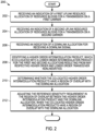
- FIG. 2 illustrates a flow diagram 200 in a user equipment for adjusting reference sensitivity requirement when higher order intermodulation products, which are co-located with lower order intermodulation products overlap with a downlink allocation. More specifically, the flow diagram 200 is illustrative of a method, and includes receiving 202 an indication of a first uplink resource allocation of resource blocks for a transmission on a first carrier, and receiving 204 an indication of a second uplink resource allocation of resource blocks for a transmission on a second carrier. An indication of a downlink allocation for receiving a downlink signal is further received 206.
- a higher order intermodulation product which is co-located with a lower order intermodulation product for the first and second allocations resulting from any respective higher order and lower order transceiver nonlinearities is identified 208.
- a determination 210 is then made as to whether the co-located higher order intermodulation products have a region of overlap with the downlink allocation.
- the reference sensitivity requirement in the region of overlap between the higher order intermodulation product and the downlink allocation is adjusted 212.
- a method consistent with flow diagram 200 illustrated in FIG. 2 can further provide for where adjusting the reference sensitivity requirement in the region of overlap between the higher intermodulation product and the downlink allocation includes relaxing the reference sensitivity.
- an amount that the reference sensitivity is relaxed can correspond to an amount of the noise rise in a receiver of the user equipment resulting from the higher order intermodulation product.
- adjusting the reference sensitivity requirement in the region of overlap between the higher intermodulation product and the downlink allocation can include a suspension of the reference sensitivity requirement.
- the lower order intermodulation product can correspond to a second order intermodulation product and the higher order intermodulation product can correspond to a fourth order intermodulation product.
- the lower order intermodulation product can correspond to a third order intermodulation product and the higher order intermodulation product can correspond to a fifth order intermodulation product.
- the higher order intermodulation product can be two orders higher than the lower order intermodulation product.
- a difference in an order of the lower order intermodulation product and an order of the higher order intermodulation product can be an even number.
- determining whether the co-located higher order intermodulation products have a region of overlap with the downlink allocation can include instances where the lower order intermodulation products do not have a region of overlap with the downlink allocation.
- the transmission on the first carrier and the transmission on the second carrier can support carrier aggregation, which includes a combination of different spectrum bands to form a larger channel to transmit data.
- the transmission on the first carrier and the transmission on the second carrier can support dual carrier operation.
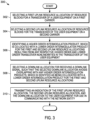
- FIG. 3 is a flow diagram 300 in a network entity for selecting a downlink allocation for use by a user equipment for receiving a downlink signal, which avoids overlap with higher order intermodulation products that are co-located with lower order intermodulation products.
- the flow diagram 300 is similarly illustrative of a method.
- the flow diagram 300 includes selecting 302 a first uplink resource allocation of resource blocks for a transceiver of a user equipment on a first carrier, and selecting 304 a second uplink resource allocation of resource blocks for the transceiver of the user equipment on a second carrier
- a higher order intermodulation product, which is co-located with a lower order intermodulation product for the first and second uplink resource allocations resulting from any respective higher order and lower order transceiver nonlinearities in the transceiver of the user equipment is then identified 306.
- a downlink allocation for receiving a downlink signal is then selected 308, such that the selected downlink allocation avoids overlapping with any higher order intermodulation products, which is identified as being co-located with a lower order intermodulation product for the first and second uplink resource allocations.
- An indication of the first uplink resource allocation, the second uplink resource allocation, and the downlink allocation is then transmitted 310 to the user equipment for use in communicating with the network entity.
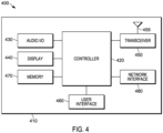
- FIG. 4 is an exemplary block diagram of an apparatus 400, such as the wireless communication device 110, according to a possible embodiment.
- the apparatus 400 can include a housing 410, a controller 420 within the housing 410, audio input and output circuitry 430 coupled to the controller 420, a display 440 coupled to the controller 420, a transceiver 450 coupled to the controller 420, an antenna 455 coupled to the transceiver 450, a user interface 460 coupled to the controller 420, a memory 470 coupled to the controller 420, and a network interface 480 coupled to the controller 420.
- the apparatus 400 can perform the methods described in all the embodiments
- the display 440 can be a viewfinder, a liquid crystal display (LCD), a light emitting diode (LED) display, a plasma display, a projection display, a touch screen, or any other device that displays information.
- the transceiver 450 can include a transmitter and/or a receiver.
- the audio input and output circuitry 430 can include a microphone, a speaker, a transducer, or any other audio input and output circuitry.
- the user interface 460 can include a keypad, a keyboard, buttons, a touch pad, a joystick, a touch screen display, another additional display, or any other device useful for providing an interface between a user and an electronic device.
- the network interface 480 can be a Universal Serial Bus (USB) port, an Ethernet port, an infrared transmitter/receiver, an IEEE 1394 port, a WLAN transceiver, or any other interface that can connect an apparatus to a network, device, or computer and that can transmit and receive data communication signals.
- the memory 470 can include a random access memory, a read only memory, an optical memory, a solid state memory, a flash memory, a removable memory, a hard drive, a cache, or any other memory that can be coupled to an apparatus.
- the apparatus 400 or the controller 420 may implement any operating system, such as Microsoft Windows ® , UNIX ® , or LINUX ® , Android TM , or any other operating system.
- Apparatus operation software may be written in any programming language, such as C, C++, Java or Visual Basic, for example.
- Apparatus software may also run on an application framework, such as, for example, a Java ® framework, a .NET ® framework, or any other application framework.
- the software and/or the operating system may be stored in the memory 470 or elsewhere on the apparatus 400.
- the apparatus 400 or the controller 420 may also use hardware to implement disclosed operations.
- the controller 420 may be any programmable processor.
- Disclosed embodiments may also be implemented on a general-purpose or a special purpose computer, a programmed microprocessor or microprocessor, peripheral integrated circuit elements, an application-specific integrated circuit or other integrated circuits, hardware/electronic logic circuits, such as a discrete element circuit, a programmable logic device, such as a programmable logic array, field programmable gate-array, or the like.
- the controller 420 may be any controller or processor device or devices capable of operating an apparatus and implementing the disclosed embodiments. Some or all of the additional elements of the apparatus 400 can also perform some or all of the operations of the disclosed embodiments.
- the flow diagrams and/or methods of this disclosure can be implemented on a programmed processor.
- the controllers, flowcharts, and modules may also be implemented on a general purpose or special purpose computer, a programmed microprocessor or microcontroller and peripheral integrated circuit elements, an integrated circuit, a hardware electronic or logic circuit such as a discrete element circuit, a programmable logic device, or the like.
- any device on which resides a finite state machine capable of implementing the flowcharts shown in the figures may be used to implement the processor functions of this disclosure.
Description
- The present disclosure is directed to a method and apparatus for adjusting for higher intermodulation products co-located with lower order intermodulation products, such as defining adjustments for reference sensitivity power level requirements in response to considering higher order intermodulation products, which overlaps one of the user equipment downlink allocations.
- Presently, user equipment, such as wireless communication devices, communicate with other communication devices using wireless signals, such as within a network environment that can include one or more cells within which various communication connections with the network and other devices operating within the network can be supported. Network environments often involve one or more sets of standards, which each define various aspects of any communication connection being made when using the corresponding standard within the network environment. Examples of developing and/or existing standards include new radio access technology (NR), Long Term Evolution (LTE), Universal Mobile Telecommunications Service (UMTS), Global System for Mobile Communication (GSM), and/or Enhanced Data GSM Environment (EDGE).
- In order to support greater data throughputs, service providers have been increasingly looking at techniques which extend the available bandwidth that is allowed to be used by a particular user within the system. At least a couple of bandwidth extending techniques include the use of carrier aggregation and/or dual carrier, where multiple frequency bands are selected to operate together. For example, by utilizing more than one carrier through carrier aggregation it may be possible to increase the overall transmission bandwidth associated with a particular data channel and correspondingly enhance the data capacity of that channel. Additionally and/or alternatively, a dual or multiple carrier approach can allow two or more spectrum allocations to be paired and/or used in parallel, which similarly can support the ability of enhanced data throughput.
- However, the use of data resources from multiple frequency bands and/or spectrum allocations together in one or more uplinks has the potential to produce various higher and lower order intermodulation products from a mixing of these signals due to non-linearities in the transceiver that can couple back in through the antenna and possibly interfere with signaling present on a downlink channel. In some cases, the intermodulation products resulting from the multiple uplink allocations can have a wider bandwidth, than the respective individual original uplinks, which can combine and extend to interfere with the frequencies associated with the downlink allocation. In at least some instances, a higher order intermodulation product may overlap with a downlink allocation, even in instances where a lower order intermodulation product does not.
- The present inventor has recognized that it may be beneficial to consider accommodations for instances in which higher order intermodulation products may overlap with a downlink allocation, including instances in which the lower order intermodulation products do not overlap with the downlink allocation. For example, it may be beneficial for the downlink allocation to be scheduled so as to avoid such concerns, or for transceiver testing requirements to be relaxed when such a condition is detected as being present or possible.
-
US 2017/0318587 A1 andUS 2017/054535 A1 each describe a method for transmitting and receiving signal by aggregating a plurality of downlink carriers and two uplink carriers.US 9,859,947 B2 US 8,861,413 B2 relates to measures for enabling power control for inter-band multi-carrier capable devices, such as e.g. inter-band carrier aggregation capable devices. - The invention is defined by the appended claims. Claim 1 defines a method in a user equipment and claim 9 defines a user equipment in a communication network. In the following, any method and/or apparatus referred to as embodiments but nevertheless do not fall within the scope of the appended claims are to be understood as examples helpful in understanding the invention.
- The present application provides a method in a wireless communication device. The method includes receiving an indication of a first uplink resource allocation of resource blocks for a transmission on a first carrier, and receiving an indication of a second uplink resource allocation of resource blocks for a transmission on a second carrier. An indication of a downlink allocation for receiving a downlink signal is further received. A higher order intermodulation product, which is co-located with a lower order intermodulation product for the first and second allocations resulting from any respective higher order and lower order transceiver nonlinearities is identified. A determination is then made as to whether the co-located higher order intermodulation products have a region of overlap with the downlink allocation. When the co-located higher order intermodulation products have a region of overlap with the downlink allocation, the reference sensitivity requirement in the region of overlap between the higher order intermodulation product and the downlink allocation is adjusted.
- In at least some embodiments, determining whether the co-located higher order intermodulation products have a region of overlap with the downlink allocation includes instances where the lower order intermodulation products do not have a region of overlap with the downlink allocation.
- In some instances, the transmission on the first carrier and the transmission on the second carrier support carrier aggregation, which can include a combination of different spectrum bands to form a larger bandwidth channel to transmit data.
- In some instances, the transmission on the first carrier and the transmission on the second carrier can support dual carrier operation.
- The present application further provides a user equipment in a communication network. The user equipment includes a transceiver that sends and receives signals between the user equipment and a network entity of the communication network including receiving an indication of a first uplink resource allocation of resource blocks for a transmission on a first carrier, receiving an indication of a second uplink resource allocation of resource blocks for a transmission on a second carrier, and receiving an indication of a downlink allocation for receiving a downlink signal. The user equipment further includes a controller that identifies a higher order intermodulation product, which is co-located with a lower order intermodulation product for the first and second allocations resulting from any respective higher order and lower order transceiver nonlinearities, and determines whether the co-located higher order intermodulation products have a region of overlap with the downlink allocation. When the co-located higher order intermodulation products have a region of overlap with the downlink allocation, the controller adjusts the reference sensitivity requirement in the region of overlap between the higher order intermodulation product and the downlink allocation.
- The present application still further provides a method in a network entity. The method includes selecting a first uplink resource allocation of resource blocks for a transceiver of a user equipment on a first carrier, and selecting a second uplink resource allocation of resource blocks for the transceiver of the user equipment on a second carrier. A higher order intermodulation product, which is co-located with a lower order intermodulation product for the first and second uplink resource allocations resulting from any respective higher order and lower order transceiver nonlinearities in the transceiver of the user equipment is then identified. A downlink allocation for receiving a downlink signal is then selected, such that the selected downlink allocation avoids overlapping with any higher order intermodulation products, which is identified as being co-located with a lower order intermodulation product for the first and second uplink resource allocations. An indication of the first uplink resource allocation, the second uplink resource allocation, and the downlink allocation is then transmitted to the user equipment for use in communicating with the network entity.
- Further yet, the present application provides a network entity, which includes a controller that selects a first uplink resource allocation of resource blocks for a transceiver of a user equipment on a first carrier, and selects a second uplink resource allocation of resource blocks for the transceiver of the user equipment on a second carrier. The controller further identifies a higher order intermodulation product, which is co-located with a lower order intermodulation product for the first and second uplink resource allocations resulting from any respective higher order and lower order transceiver nonlinearities, and selects a downlink allocation for receiving a downlink signal, such that the selected downlink allocation avoids overlapping with any higher order intermodulation products, which is identified as being co-located with a lower order intermodulation product for the first and second uplink resource allocations. The network entity further includes a transceiver that sends and receives signals between the user equipment and the network entity including transmitting an indication of the first uplink resource allocation, the second uplink resource allocation, and the downlink allocation to the user equipment for use in communicating with the network entity.
- These and other features, and advantages of the present application are evident from the following description of one or more preferred embodiments, with reference to the accompanying drawings.
-
-
FIG. 1 is a block diagram of an exemplary network environment in which the present invention is adapted to operate; -
FIG. 2 is a flow diagram in a user equipment for adjusting reference sensitivity requirement when higher order intermodulation products, which are co-located with lower order intermodulation products, overlap with a downlink allocation; -
FIG. 3 is a flow diagram in a network entity for selecting a downlink allocation for use by a user equipment for receiving a downlink signal, which avoids overlap with higher order intermodulation products that are co-located with lower order intermodulation products; and -
FIG. 4 is an exemplary block diagram of an apparatus according to a possible embodiment. - While the present disclosure is susceptible of embodiment in various forms, there is shown in the drawings and will hereinafter be described presently preferred embodiments with the understanding that the present disclosure is to be considered an exemplification of the invention and is not intended to limit the invention to the specific embodiments illustrated.
- Embodiments provide a method and apparatus for adjusting for higher order intermodulation products co-located with lower order intermodulation products.
-
FIG. 1 is an example block diagram of asystem 100 according to a possible embodiment. Thesystem 100 can include awireless communication device 110, such as User Equipment (UE), abase station 120, such as an enhanced NodeB (eNB) or next generation NodeB (gNB), and anetwork 130. Thewireless communication device 110 can be a wireless terminal, a portable wireless communication device, a smartphone, a cellular telephone, a flip phone, a personal digital assistant, a personal computer, a selective call receiver, a tablet computer, a laptop computer, or any other device that is capable of sending and receiving communication signals on a wireless network. - The
network 130 can include any type of network that is capable of sending and receiving wireless communication signals. For example, thenetwork 130 can include a wireless communication network, a cellular telephone network, a Time Division Multiple Access (TDMA)-based network, a Code Division Multiple Access (CDMA)-based network, an Orthogonal Frequency Division Multiple Access (OFDMA)-based network, a Long Term Evolution (LTE) network, a 5th generation (5G) network, a 3rd Generation Partnership Project (3GPP)-based network, a satellite communications network, a high altitude platform network, the Internet, and/or other communications networks. - Recent co-existence studies for NSA NR have considered harmonics and intermodulation (IM) products up to at least 5th order to determine if they interfere with the UE downlink carrier or with other bands. One such example includes 3GPP TR 37.863-01-01 V0.3.0 (2017-11), entitled Dual connectivity (DC) band combinations of LTE 1DL/1UL + one NR band. At least one aspect which may be missing from this and other studies is the impact of higher order IM products which are co-located with lower order IM products. While these higher order IM's have less power than the lower order IM's with which they are co-located, they are wider and therefore may overlap the UE downlink or other bands even when the lower-order IM's do not. Furthermore, the higher order IM products which are co-located with the lower order IM's may have more power than the higher order IM products which are not co-located with lower order 1M's. as a result, if the higher order IM products which are not co-located with lower order IM's have sufficient power to interfere with the downlink or with other bands, then it follows that the same may be true for the higher order IM products which are co-located with the lower order IM products.
- It can be noted that these co-located higher order IM's are implicitly addressed in the TS 36.101 spurious emission exceptions in the form of expanded regions for harmonic exceptions due to spectral "spreading". The higher order co-located IM's are also implicitly addressed in the harmonic Refsens exceptions defined for the case when the harmonic does not overlap the UE downlink allocation but is adjacent to it.
- In accordance with at least one possible embodiment, the present disclosure includes defining the reference sensitivity power level (Refsens) relaxations or no Refens requirement for the user equipment (UE) in the case that a higher order intermodulation product of multiple uplink carriers is co-located with a lower order intermodulation product and the higher order intermodulation product overlaps one of the UE downlink allocations. Previously, the 3GPP RAN4 specification has defined Refsens relaxations or no Refsens requirement in the case that intermodulation products from multiple carriers fall on the UE's downlink allocation. However, RAN4 has ignored the issue of higher order intermodulation products which are co-located with lower order intermodulation products. While the higher order modulation products have less power, in general, than the lower order intermodulation products, these higher order modulation products have wider bandwidth and thus can impinge on the UE downlink allocation even when the lower order IM product does not. In the case that the lower order IM overlaps the UE's downlink, the region of overlap will be extended by the co-located higher order IM product.
- Historically, Refsens relaxations or no Refsens requirement may have generally been provided in the case that intermodulation products interfere with the UE's downlink receiver. However, they generally have failed to address instances, in which higher order intermodulation products are co-located with lower order intermodulation products and the higher order intermodulation products interfere with the UE's downlink receiver while the co-located lower order IM product does not. In the case that the lower order IM overlaps the UE's downlink, the region of overlap will be extended by the co-located higher order IM product. Examples of this issue can be shown by considering the fourth order intermodulation products that are co-located with the second order intermodulation products, and similarly, the fifth order intermodulation products that are co-located with third order intermodulation products. It can be noted that only 'even' higher order intermodulation products are co-located with 'even' lower order intermodulation products, and only 'odd' higher order intermodulation products are co-located with 'odd' lower order intermodulation products.
- According to a possible embodiment, it may be beneficial to identify the higher order intermodulation products which are co-located with lower order intermodulation products and which interfere with the UE's downlink allocation. For these higher-order intermodulation products co-located with lower order intermodulation products, it is may be beneficial to define Refsens relaxations or no Refsens requirement in the case that the higher order IM overlaps the UE's downlink allocation while the lower order IM does not. In the case that the lower order IM overlaps the UE's downlink, the region of overlap will be extended by the higher order IM and either Refsens relaxation or no Refsens requirement could be defined for this extended overlap region.
- The third, fourth, and fifth powers of a two carrier signal of the form

- Correspondingly, the two carrier third-order nonlinearity can be represented as:


- The harmonics and IM products which result from the expansion can be found in Table 1, below. The terms noted with an asterisk, namely IM #'s 7-10, have typically not been included in co-existence studies. However, it should be noted that multiplicative coefficients for the noted terms are at least as large as those for the IM terms normally included for the third order non-linearity.
Table 1: IM Products and Harmonics due to 3nd Order Non-linearity IM # Center Frequency IM Bandwidth Multiplicative Coefficient 1 3*f1 3*W1 0.25 2 3*f2 3*W2 0.25 3 |2*f1 - f2| 2*W1 + W2 0.75 4 |f1 - 2*f2 | W1 + 2*W2 0.75 5 2*f1 + f2 2*W1 + W2 0.75 6 f1 + 2*f2 W1 + 2*W2 0.75 7* f1 3*W1 0.75 8* f1 W1 + 2*W2 1.5 9* f2 3*W2 0.75 10* f2 2*W1 + W2 1.5 - The IM products 7 and 9 are the source of adjacent channel leakage in single carrier operation. The IM products 8 and 10 occur in dual-carrier operation and unless W1 and W2 are equal, one of these IM products will be wider than the corresponding IM for single carrier operation.
- If the multiplicative coefficient of each term is ignored, Table 1 can be simplified slightly as in Table 1a below.
Table 1a: IM Products and Harmonics due to 3nd Order Non-linearity IM# Center Frequency IM Bandwidth 1 3*f1 3*W1 2 3*f2 3*W2 3 | 2*f1 - f2 | 2*W1 + W2 4 | f1 - 2*f2 | W1 + 2*W2 5 2*f1 + f2 2*W1 + W2 6 f1 + 2*f2 W1 + 2*W2 7* f1 max(3*W1, W1 + 2*W2 ) 8* f2 max(3*W2, W2 + 2*W1 ) - The two carrier fourth-order nonlinearity can be represented as:


- The harmonics and IM products which result from the expansion can be found in Table 2, below. The terms noted with an asterisk (direct current terms are excluded), namely IM #'s 9-16, have typically not been included in co-existence studies. However, it should be noted that multiplicative coefficients for the noted terms are at least as large as those for the IM terms normally included for the fourth order non-linearity.
- The IM terms 13 and 15 at 2*f1 and 2*f2, respectively, occur also in single carrier operation and may have been addressed previously by allowing for spectral "spreading" when defining spurious exceptions for the second harmonic and also for defining Refsens relaxations for harmonics adjacent to the downlink allocation. This spectral spreading is actually due to an IM term generated by a 4th order (or higher even order) non-linearity falling on top of the second harmonic.
Table 2: IM Products and Harmonics due to 4th Order Non-linearity IM# Center Frequency IM Bandwidth Multiplicative Coefficient 1 4*f1 4*W1 0.125 2 4*f2 4*W2 0.125 3 | 3*f1 - f2 | 3*W1 + W2 0.5 4 | f1 - 3*f2 | W1 + 3*W2 0.5 5 3*f1 + f2 3*W1 + W2 0.5 6 f1 + 3*f2 W1 + 3*W2 0.5 7 | 2*f1 - 2*f2 | 2*W1 + 2*W2 0.75 8 2*f1 + 2*f2 2*W2 + 2*W1 0.75 9* | f1 - f2 | 3*W1 + W2 1.5 10* | f1 - f2 | W1 + 3*W2 1.5 11* f1 + f2 3*W1 + W2 1.5 12* f1 + f2 W1 + 3*W2 1.5 13* 2*f1 4*W1 0.5 14* 2*f1 2*W1 + 2*W2 1.5 15* 2*f2 4*W2 0.5 16* 2*f2 2*W1 + 2*W2 1.5 17 0 4*W1 0.375 18 0 2*W1 + 2*W2 1.5 19 0 4*W2 0.375 - If the multiplicative coefficient of each term is ignored and the direct current terms are removed, Table 2 can be simplified slightly as in Table 2a below.
Table 2a: IM Products and Harmonics due to 4th Order Non-linearity IM# Center Frequency IM Bandwidth 1 4*f1 4*W1 2 4*f2 4*W2 3 | 3*f1 - f2 | 3*W1 + W2 4 | f1 - 3*f2 | W1 + 3*W2 5 3*f1 + f2 3*W1 + W2 6 f1 + 3*f2 W1 + 3*W2 7 | 2*f1 - 2*f2 | 2*W1 + 2*W2 8 2*f1 + 2*f2 2*W2 + 2*W1 9* | f1 - f2 | max(3*W1 + W2, W1 + 3*W2 ) 10* f1 + f2 max(3*W1 + W2, W1+ 3*W2) 11* 2*f1 max(4*W1, 2*W1 + 2*W2) 12* 2*f2 max(4*W2, 2*W1 + 2*W2) - The two carrier fifth-order nonlinearity can be represented as:


- The harmonics and IM products which result from the expansion can be found in Table 3, below. The terms noted with an asterisk, namely IM #'s 11-28, have typically not been included in co-existence studies. However, it should be noted that multiplicative coefficients for the noted terms are at least as large as those for the IM terms normally included for the fifth order non-linearity.
- The IM terms 11 and 13 at 3∗f1 and 3∗f2, respectively, occur also in single carrier operation and have been addressed previously by allowing for spectral "spreading" when defining spurious exceptions for the third harmonic and also for defining Refsens relaxations for harmonics adjacent to the downlink allocation. This spectral spreading is actually due to an IM term generated by a 5th order (or higher odd order) non-linearity falling on top of the third harmonic.
Table 3: IM Products and Harmonics due to 5nd Order Non-linearity IM# Center Frequency IM Bandwidth Multiplicative Coefficient 1 5*f1 5*W1 0.0625 2 5*f2 5*W2 0.0625 3 | 4*f, - f2 | 4*W1 + W2 0.3125 4 | f1 - 4*f2 | W1 + 4*W2 0.3125 5 4*f1 + f2 4*W1 + W2 0.3125 6 f1 + 4*f2 W1 + 4*W2 0.3125 7 | 3*f1 - 2*f2 | 3*W1 + 2*W2 0.625 8 | 2*f1 - 3*f2 | 2*W2 + 3*W1 0.625 9 3*f1 + 2*f2 3*W1 + 2*W2 0.625 10 2*f1 + 3*f2 2*W2 + 3*W1 0.625 11* 3*f1 5*W1 0.3125 12* 3*f1 3*W1 + 2*W2 1.25 13* 3*f2 5*W2 0.3125 14* 3*f2 2*W1 + 3*W2 1.25 15* | 2*f1 - f2 | 4*W1 + W2 1.25 16* | 2*f1 - f2 | 2*W1 + 3*W2 1.875 17* | f1 - 2*f2 | W1 + 4*W2 1.25 18* | f1 - 2*f2 | 3*W1 + 2*W2 1.875 19* 2*f1 + f2 4*W1 + W2 1.25 20* 2*f1 + f2 2*W1 + 3*W2 1.875 21* f1 + 2*f2 W1 + 4*W2 1.25 22* f1 + 2*f2 3*W1 + 2*W2 1.875 23* f1 5*W1 0.625 24* f1 3*W1 + 2*W2 3.75 25* f1 W1 + 4*W2 1.875 26* f2 5*W2 0.625 27* f2 2*W1 + 3*W2 3.75 28* f2 4*W1 + W2 1.875 - If the multiplicative coefficient of each term is ignored, Table 3 can be simplified slightly as in Table 3a below.
Table 3a: IM Products and Harmonics due to 5nd Order Non-linearity IM# Center Frequency IM Bandwidth 1 5*f1 5*W1 2 5*f2 5*W2 3 | 4*f1 - f2 | 4*W1 + W2 4 | f1 - 4*f2 | W1 + 4*W2 5 4*f1 + f2 4*W1 + W2 6 f1 + 4*f2 W1 + 4*W2 7 | 3*f1 - 2*f2 | 3*W1 + 2*W2 8 | 2*f1 - 3*f2 | 2*W2 + 3*W1 9 3*f1 + 2*f2 3*W1 + 2*W2 10 2*f1 + 3*f2 2*W2 + 3*W1 11* 3*f1 max(5*W1, 3*W1 + 2*W2) 12* 3*f2 max(5*W2, 2*W1 + 3*W2) 13* | 2*f1 - f2 | max(4*W1 + W2, 2*W1 + 3*W2) 14* | f1 - 2*f2 | max(W1 + 4*W2, 3*W1 + 2*W2) 15* 2*f1 + f2 max(4*W1 + W2, 2*W1 + 3*W2) 16* f1 + 2*f2 max(W1 + 4*W2, 3*W1 + 2*W2) 17* f1 max(5*W1, 3*W1 + 2*W2, W1 + 4*W2) 18* f2 max(5*W2, 2*W1 + 3*W2, 4*W1 + W2) - As such, the two-carrier third, fourth and fifth order nonlinearities have been expanded in order to enumerate the intermodulation terms and harmonics resulting from these nonlinearities. Recent co-existence studies for NSA NR have generally not included the IM products generated by higher order non-linearities which fall on top of IM products generated by lower order non-linearities. However, as these co-located higher order IM products may have more power than the higher order IM products which are not co-located with lower order IM's, they should also be included in the NSA NR co-existence studies. Thus, it would be beneficial for the noted IM products in Tables 1, 2, and 3 be considered for inclusion in the dual-carrier self-desense analysis, such as for non-standalone (NSA) fifth generation (5G) standards, and corresponding reference sensitivity relaxations be defined, if necessary, including where the IM products fall in a downlink allocation.
-
FIG. 2 illustrates a flow diagram 200 in a user equipment for adjusting reference sensitivity requirement when higher order intermodulation products, which are co-located with lower order intermodulation products overlap with a downlink allocation. More specifically, the flow diagram 200 is illustrative of a method, and includes receiving 202 an indication of a first uplink resource allocation of resource blocks for a transmission on a first carrier, and receiving 204 an indication of a second uplink resource allocation of resource blocks for a transmission on a second carrier. An indication of a downlink allocation for receiving a downlink signal is further received 206. A higher order intermodulation product, which is co-located with a lower order intermodulation product for the first and second allocations resulting from any respective higher order and lower order transceiver nonlinearities is identified 208. Adetermination 210 is then made as to whether the co-located higher order intermodulation products have a region of overlap with the downlink allocation. When the co-located higher order intermodulation products have a region of overlap with the downlink allocation, the reference sensitivity requirement in the region of overlap between the higher order intermodulation product and the downlink allocation is adjusted 212. - A method consistent with flow diagram 200 illustrated in
FIG. 2 can further provide for where adjusting the reference sensitivity requirement in the region of overlap between the higher intermodulation product and the downlink allocation includes relaxing the reference sensitivity. In some instances, an amount that the reference sensitivity is relaxed can correspond to an amount of the noise rise in a receiver of the user equipment resulting from the higher order intermodulation product. In some instances, adjusting the reference sensitivity requirement in the region of overlap between the higher intermodulation product and the downlink allocation can include a suspension of the reference sensitivity requirement. - In some instances, the lower order intermodulation product can correspond to a second order intermodulation product and the higher order intermodulation product can correspond to a fourth order intermodulation product. In some instances, the lower order intermodulation product can correspond to a third order intermodulation product and the higher order intermodulation product can correspond to a fifth order intermodulation product. In some instances, the higher order intermodulation product can be two orders higher than the lower order intermodulation product. In some instances, a difference in an order of the lower order intermodulation product and an order of the higher order intermodulation product can be an even number.
- In some instances, determining whether the co-located higher order intermodulation products have a region of overlap with the downlink allocation can include instances where the lower order intermodulation products do not have a region of overlap with the downlink allocation.
- In some instances, the transmission on the first carrier and the transmission on the second carrier can support carrier aggregation, which includes a combination of different spectrum bands to form a larger channel to transmit data. In some instances, the transmission on the first carrier and the transmission on the second carrier can support dual carrier operation.
-
FIG. 3 is a flow diagram 300 in a network entity for selecting a downlink allocation for use by a user equipment for receiving a downlink signal, which avoids overlap with higher order intermodulation products that are co-located with lower order intermodulation products. The flow diagram 300 is similarly illustrative of a method. The flow diagram 300 includes selecting 302 a first uplink resource allocation of resource blocks for a transceiver of a user equipment on a first carrier, and selecting 304 a second uplink resource allocation of resource blocks for the transceiver of the user equipment on a second carrier A higher order intermodulation product, which is co-located with a lower order intermodulation product for the first and second uplink resource allocations resulting from any respective higher order and lower order transceiver nonlinearities in the transceiver of the user equipment is then identified 306. A downlink allocation for receiving a downlink signal is then selected 308, such that the selected downlink allocation avoids overlapping with any higher order intermodulation products, which is identified as being co-located with a lower order intermodulation product for the first and second uplink resource allocations. An indication of the first uplink resource allocation, the second uplink resource allocation, and the downlink allocation is then transmitted 310 to the user equipment for use in communicating with the network entity. -
FIG. 4 is an exemplary block diagram of anapparatus 400, such as thewireless communication device 110, according to a possible embodiment. Theapparatus 400 can include ahousing 410, acontroller 420 within thehousing 410, audio input andoutput circuitry 430 coupled to thecontroller 420, adisplay 440 coupled to thecontroller 420, atransceiver 450 coupled to thecontroller 420, an antenna 455 coupled to thetransceiver 450, auser interface 460 coupled to thecontroller 420, amemory 470 coupled to thecontroller 420, and anetwork interface 480 coupled to thecontroller 420. Theapparatus 400 can perform the methods described in all the embodiments - The
display 440 can be a viewfinder, a liquid crystal display (LCD), a light emitting diode (LED) display, a plasma display, a projection display, a touch screen, or any other device that displays information. Thetransceiver 450 can include a transmitter and/or a receiver. The audio input andoutput circuitry 430 can include a microphone, a speaker, a transducer, or any other audio input and output circuitry. Theuser interface 460 can include a keypad, a keyboard, buttons, a touch pad, a joystick, a touch screen display, another additional display, or any other device useful for providing an interface between a user and an electronic device. Thenetwork interface 480 can be a Universal Serial Bus (USB) port, an Ethernet port, an infrared transmitter/receiver, an IEEE 1394 port, a WLAN transceiver, or any other interface that can connect an apparatus to a network, device, or computer and that can transmit and receive data communication signals. Thememory 470 can include a random access memory, a read only memory, an optical memory, a solid state memory, a flash memory, a removable memory, a hard drive, a cache, or any other memory that can be coupled to an apparatus. - The
apparatus 400 or thecontroller 420 may implement any operating system, such as Microsoft Windows®, UNIX®, or LINUX®, Android™, or any other operating system. Apparatus operation software may be written in any programming language, such as C, C++, Java or Visual Basic, for example. Apparatus software may also run on an application framework, such as, for example, a Java® framework, a .NET® framework, or any other application framework. The software and/or the operating system may be stored in thememory 470 or elsewhere on theapparatus 400. Theapparatus 400 or thecontroller 420 may also use hardware to implement disclosed operations. For example, thecontroller 420 may be any programmable processor. Disclosed embodiments may also be implemented on a general-purpose or a special purpose computer, a programmed microprocessor or microprocessor, peripheral integrated circuit elements, an application-specific integrated circuit or other integrated circuits, hardware/electronic logic circuits, such as a discrete element circuit, a programmable logic device, such as a programmable logic array, field programmable gate-array, or the like. In general, thecontroller 420 may be any controller or processor device or devices capable of operating an apparatus and implementing the disclosed embodiments. Some or all of the additional elements of theapparatus 400 can also perform some or all of the operations of the disclosed embodiments. - The flow diagrams and/or methods of this disclosure can be implemented on a programmed processor. However, the controllers, flowcharts, and modules may also be implemented on a general purpose or special purpose computer, a programmed microprocessor or microcontroller and peripheral integrated circuit elements, an integrated circuit, a hardware electronic or logic circuit such as a discrete element circuit, a programmable logic device, or the like. In general, any device on which resides a finite state machine capable of implementing the flowcharts shown in the figures may be used to implement the processor functions of this disclosure.
- While this disclosure has been described with specific embodiments thereof, it is evident that many alternatives, modifications, and variations will be apparent to those skilled in the art. For example, various components of the embodiments may be interchanged, added, or substituted in the other embodiments. Also, all of the elements of each figure are not necessary for operation of the disclosed embodiments. For example, one of ordinary skill in the art of the disclosed embodiments would be enabled to make and use the teachings of the disclosure by simply employing the elements of the independent claims. Accordingly, embodiments of the disclosure as set forth herein are intended to be illustrative, not limiting.
- In this document, relational terms such as "first", "second", and the like may be used solely to distinguish one entity or action from another entity or action without necessarily requiring or implying any actual such relationship or order between such entities or actions. The phrase "at least one of, "at least one selected from the group of", or "at least one selected from" followed by a list is defined to mean one, some, or all, but not necessarily all of, the elements in the list. The terms "comprises", "comprising", "including", or any other variation thereof, are intended to cover a non-exclusive inclusion, such that a process, method, article, or apparatus that comprises a list of elements does not include only those elements but may include other elements not expressly listed or inherent to such process, method, article, or apparatus. An element proceeded by "a", "an", or the like does not, without more constraints, preclude the existence of additional identical elements in the process, method, article, or apparatus that comprises the element. Also, the term "another" is defined as at least a second or more. The terms "including", "having", and the like, as used herein, are defined as "comprising". Furthermore, the background section is written as the inventor's own understanding of the context of some embodiments at the time of filing and includes the inventor's own recognition of any problems with existing technologies and/or problems experienced in the inventor's own work.
Claims (15)
- A method in a user equipment comprising:receiving an indication of a first uplink resource allocation of resource blocks for a transmission on a first carrier;receiving an indication of a second uplink resource allocation of resource blocks for a transmission on a second carrier;receiving an indication of a downlink allocation for receiving a downlink signal;identifying a higher order intermodulation product for the first and second uplink resource allocations, which is co-located with a lower order intermodulation product for the first and second uplink resource allocations, resulting from any respective higher order and lower order transceiver nonlinearities;determining whether the identified higher order intermodulation product has a region of overlap with the downlink allocation; andadjusting the reference sensitivity requirement in the region of overlap between the higher order intermodulation product and the downlink allocation, when the higher order intermodulation product has a region of overlap with the downlink allocation.
- A method in accordance with claim 1, wherein adjusting the reference sensitivity requirement in the region of overlap between the higher intermodulation product and the downlink allocation includes relaxing the reference sensitivity, or a suspension of the reference sensitivity requirement.
- A method in accordance with claim 2, wherein an amount that the reference sensitivity is relaxed corresponds to an amount of the noise rise in a receiver of the user equipment resulting from the higher order intermodulation product.
- A method in accordance with claim 1, wherein the lower order intermodulation product corresponds to either:a second order intermodulation product and the higher order intermodulation product corresponds to a fourth order intermodulation product; ora third order intermodulation product and the higher order intermodulation product corresponds to a fifth order intermodulation product.
- A method in accordance with claim 1, wherein the higher order intermodulation product is two orders higher than the lower order intermodulation product.
- A method in accordance with claim 1, wherein a difference in an order of the lower order intermodulation product and an order of the higher order intermodulation product is an even number.
- A method in accordance with claim 1, wherein the transmission on the first carrier and the transmission on the second carrier support carrier aggregation, which includes a combination of different spectrum bands to form a larger bandwidth channel to transmit data.
- A method in accordance with claim 1, wherein the transmission on the first carrier and the transmission on the second carrier support dual carrier operation.
- A user equipment in a communication network, the user equipment comprising:a transceiver arranged to send and receive signals between the user equipment and a network entity of the communication network, the transceiver further arranged to receive an indication of a first uplink resource allocation of resource blocks for a transmission on a first carrier, receive an indication of a second uplink resource allocation of resource blocks for a transmission on a second carrier, and receive an indication of a downlink allocation for receiving a downlink signal; anda controller arranged to identify a higher order intermodulation product for the first and second uplink resource allocations, which is co-located with a lower order intermodulation product for the first and second uplink resource allocations, resulting from any respective higher order and lower order transceiver nonlinearities, and determine whether the higher order intermodulation product has a region of overlap with the downlink allocation;wherein, when the higher order intermodulation product has a region of overlap with the downlink allocation, the controller is further arranged to adjust the reference sensitivity requirement in the region of overlap between the higher order intermodulation product and the downlink allocation.
- A user equipment in accordance with claim 9, wherein the controller is arranged to adjust the reference sensitivity requirement in the region of overlap between the higher intermodulation product and the downlink allocation by either:relaxing the reference sensitivity; orincludes a suspension of the reference sensitivity requirement.
- A user equipment in accordance with claim 10, wherein an amount that the controller is arranged to relax the reference sensitivity, corresponds to an amount of the noise rise in the transceiver resulting from the higher order intermodulation product.
- A user equipment in accordance with claim 9, wherein the lower order intermodulation product corresponds to a second order intermodulation product and the higher order intermodulation product corresponds to a fourth order intermodulation product.
- A user equipment in accordance with claim 9, wherein the lower order intermodulation product corresponds to a third order intermodulation product and the higher order intermodulation product correspond to a fifth order intermodulation product.
- A user equipment in accordance with claim 9, wherein the higher order intermodulation product is two orders higher than the lower order intermodulation product.
- A user equipment in accordance with claim 9, wherein a difference in a rank of the lower order intermodulation product and a rank of the higher order intermodulation product is an even number.
Priority Applications (1)
| Application Number | Priority Date | Filing Date | Title |
|---|---|---|---|
| EP23193190.8A EP4254810A3 (en) | 2018-01-12 | 2019-01-11 | Method and apparatus for adjusting for higher order intermodulation products co-located with lower order intermodulation products |
Applications Claiming Priority (2)
| Application Number | Priority Date | Filing Date | Title |
|---|---|---|---|
| US201862617116P | 2018-01-12 | 2018-01-12 | |
| PCT/IB2019/000045 WO2019138293A1 (en) | 2018-01-12 | 2019-01-11 | Method and apparatus for adjusting for higher order intermodulation products co-located with lower order intermodulation products |
Related Child Applications (2)
| Application Number | Title | Priority Date | Filing Date |
|---|---|---|---|
| EP23193190.8A Division-Into EP4254810A3 (en) | 2018-01-12 | 2019-01-11 | Method and apparatus for adjusting for higher order intermodulation products co-located with lower order intermodulation products |
| EP23193190.8A Division EP4254810A3 (en) | 2018-01-12 | 2019-01-11 | Method and apparatus for adjusting for higher order intermodulation products co-located with lower order intermodulation products |
Publications (3)
| Publication Number | Publication Date |
|---|---|
| EP3738265A1 EP3738265A1 (en) | 2020-11-18 |
| EP3738265B1 true EP3738265B1 (en) | 2023-10-18 |
| EP3738265C0 EP3738265C0 (en) | 2023-10-18 |
Family
ID=65911203
Family Applications (2)
| Application Number | Title | Priority Date | Filing Date |
|---|---|---|---|
| EP23193190.8A Pending EP4254810A3 (en) | 2018-01-12 | 2019-01-11 | Method and apparatus for adjusting for higher order intermodulation products co-located with lower order intermodulation products |
| EP19713556.9A Active EP3738265B1 (en) | 2018-01-12 | 2019-01-11 | Method and apparatus for adjusting for higher order intermodulation products co-located with lower order intermodulation products |
Family Applications Before (1)
| Application Number | Title | Priority Date | Filing Date |
|---|---|---|---|
| EP23193190.8A Pending EP4254810A3 (en) | 2018-01-12 | 2019-01-11 | Method and apparatus for adjusting for higher order intermodulation products co-located with lower order intermodulation products |
Country Status (5)
| Country | Link |
|---|---|
| US (2) | US11190226B2 (en) |
| EP (2) | EP4254810A3 (en) |
| KR (1) | KR20200103713A (en) |
| CN (1) | CN111566978A (en) |
| WO (1) | WO2019138293A1 (en) |
Families Citing this family (3)
| Publication number | Priority date | Publication date | Assignee | Title |
|---|---|---|---|---|
| US11165455B2 (en) * | 2018-05-16 | 2021-11-02 | Telefonaktiebolaget Lm Ericsson (Publ) | Interference mitigation |
| US11893570B1 (en) * | 2019-11-22 | 2024-02-06 | United Services Automobile Association (Usaa) | Token based demand and remand system |
| DE112021004406T5 (en) * | 2020-08-21 | 2023-07-20 | Psemi Corporation | METHODS AND SYSTEMS FOR DYNAMIC RF BAND ALLOCATION |
Family Cites Families (17)
| Publication number | Priority date | Publication date | Assignee | Title |
|---|---|---|---|---|
| CN100342749C (en) * | 2001-05-25 | 2007-10-10 | 株式会社Ntt都科摩 | Information channel distributing method and communication controlling apparatus |
| US8005479B2 (en) * | 2002-11-07 | 2011-08-23 | Adaptix, Inc. | Method and apparatus for adaptive carrier allocation and power control in multi-carrier communication systems |
| US9160310B2 (en) * | 2008-04-30 | 2015-10-13 | Scott R. Velazquez | Linearity compensator for removing nonlinear distortion |
| US9509543B2 (en) * | 2009-06-26 | 2016-11-29 | Qualcomm Incorporated | Method and apparatus that facilitates interference reduction in wireless systems |
| US8583070B2 (en) * | 2010-04-20 | 2013-11-12 | Qualcomm Incorporated | Autonomous electromagnetic emissions reduction for sensitivity improvement |
| US9025478B2 (en) * | 2011-08-16 | 2015-05-05 | Google Technology Holdings LLC | Self-interference handling in a wireless communication terminal supporting carrier aggregation |
| GB2498758B (en) | 2012-01-26 | 2014-02-19 | Broadcom Corp | Power control |
| GB2502064B (en) * | 2012-05-14 | 2014-04-09 | Broadcom Corp | Power control |
| US9538518B2 (en) * | 2012-08-28 | 2017-01-03 | Lg Electronics Inc. | Method for detecting downlink control channel in wireless communication system and apparatus for same |
| EP2909985A4 (en) * | 2012-10-16 | 2016-09-14 | Nokia Solutions & Networks Oy | A technique for extremely high order im correction |
| WO2015072715A1 (en) * | 2013-11-13 | 2015-05-21 | 엘지전자 주식회사 | Terminal eliminating harmonic components and intermodulation distortions component |
| US10187186B2 (en) * | 2014-09-30 | 2019-01-22 | Qualcomm Incorporated | Uplink grant management for LTE in unlicensed spectrum |
| US20160302209A1 (en) * | 2014-11-10 | 2016-10-13 | Telefonaktiebolaget L M Ericsson (Publ) | Reducing Interference Caused by Uplink Carrier Aggregation |
| US10404314B2 (en) | 2015-08-17 | 2019-09-03 | Lg Electronics Inc. | Method for transmitting and receiving signal by aggregating three downlink carriers and two uplink carriers |
| US10333663B2 (en) | 2016-05-02 | 2019-06-25 | Lg Electronics Inc. | Method for transmitting and receiving signal by aggregating a plurality of downlink carriers and two uplink carriers |
| US10148311B2 (en) * | 2016-09-26 | 2018-12-04 | Lg Electronics Inc. | Studies about MSD level in aggregating a plurality of downlink carriers and two uplink carriers |
| KR102251841B1 (en) * | 2017-07-07 | 2021-05-14 | 베이징 시아오미 모바일 소프트웨어 컴퍼니 리미티드 | Interference coordination method and apparatus, base station, user device |
-
2019
- 2019-01-10 US US16/245,250 patent/US11190226B2/en active Active
- 2019-01-11 EP EP23193190.8A patent/EP4254810A3/en active Pending
- 2019-01-11 CN CN201980007763.XA patent/CN111566978A/en active Pending
- 2019-01-11 WO PCT/IB2019/000045 patent/WO2019138293A1/en unknown
- 2019-01-11 KR KR1020207019763A patent/KR20200103713A/en not_active Application Discontinuation
- 2019-01-11 EP EP19713556.9A patent/EP3738265B1/en active Active
-
2021
- 2021-11-30 US US17/538,690 patent/US20220094378A1/en active Pending
Also Published As
| Publication number | Publication date |
|---|---|
| WO2019138293A1 (en) | 2019-07-18 |
| EP3738265C0 (en) | 2023-10-18 |
| CN111566978A (en) | 2020-08-21 |
| US20220094378A1 (en) | 2022-03-24 |
| EP4254810A3 (en) | 2023-12-20 |
| US20190222242A1 (en) | 2019-07-18 |
| US11190226B2 (en) | 2021-11-30 |
| EP4254810A2 (en) | 2023-10-04 |
| EP3738265A1 (en) | 2020-11-18 |
| KR20200103713A (en) | 2020-09-02 |
Similar Documents
| Publication | Publication Date | Title |
|---|---|---|
| US20220094378A1 (en) | Method and Apparatus for Adjusting for Higher Order Intermodulation Products Co-Located with Lower Order Intermodulation Products | |
| US20100296488A1 (en) | Apparatus and Method for Measurement Gap Configuration | |
| EP4236092A2 (en) | Downlink control for non coherent joint transmission | |
| EP3595375B1 (en) | Method, device and system for configuring transmission direction | |
| US10999047B2 (en) | Frequency band configuration apparatus, method and communication system | |
| US11722970B2 (en) | Method and apparatus for determining per carrier additional maximum power reduction for dual carrier operation | |
| CN110431782B (en) | System, apparatus and method for performing cellular communications | |
| US11943699B2 (en) | System and method for determining PDCCH monitoring capability per component carriers in a carrier aggregation for span based PDCCH monitoring | |
| CN103597771A (en) | Discontinuous reception for carrier aggregation | |
| CN112787696A (en) | Wireless device power saving for multiple TRP transmissions | |
| WO2019134074A1 (en) | Non-anchor carrier frequency offset indication | |
| US20230188174A1 (en) | Method and Apparatus for Network Assignment of the User Equipment Transmitter Local Oscillator Frequency | |
| US20210100022A1 (en) | Downlink Control for Multi-TRP Transmissions | |
| EP3834507B1 (en) | Method and apparatus for determining per carrier additional maximum power reduction for dual carrier operation | |
| US11224057B2 (en) | Uplink time division multiplexing pattern for 5G non-standalone devices | |
| CN115606285A (en) | Control signaling for PUCCH reliability enhancement | |
| US20230397024A1 (en) | Uplink Carrier Aggregation Antenna Contention Resolution | |
| US20230319813A1 (en) | Mechanism for tb processing over multi-slot scheme | |
| US20230362943A1 (en) | Scheduling restriction enhancement for lte and nr dss | |
| EP3799502A2 (en) | Downlink control for multi-trp transmissions | |
| US20220377775A1 (en) | Radio Link Monitoring for Multi-DCI Based Transmissions | |
| CN116803157A (en) | Counting active resources for UE processing complexity related capability |
Legal Events
| Date | Code | Title | Description |
|---|---|---|---|
| STAA | Information on the status of an ep patent application or granted ep patent |
Free format text: STATUS: UNKNOWN |
|
| STAA | Information on the status of an ep patent application or granted ep patent |
Free format text: STATUS: THE INTERNATIONAL PUBLICATION HAS BEEN MADE |
|
| PUAI | Public reference made under article 153(3) epc to a published international application that has entered the european phase |
Free format text: ORIGINAL CODE: 0009012 |
|
| STAA | Information on the status of an ep patent application or granted ep patent |
Free format text: STATUS: REQUEST FOR EXAMINATION WAS MADE |
|
| 17P | Request for examination filed |
Effective date: 20200629 |
|
| AK | Designated contracting states |
Kind code of ref document: A1 Designated state(s): AL AT BE BG CH CY CZ DE DK EE ES FI FR GB GR HR HU IE IS IT LI LT LU LV MC MK MT NL NO PL PT RO RS SE SI SK SM TR |
|
| AX | Request for extension of the european patent |
Extension state: BA ME |
|
| DAV | Request for validation of the european patent (deleted) | ||
| DAX | Request for extension of the european patent (deleted) | ||
| STAA | Information on the status of an ep patent application or granted ep patent |
Free format text: STATUS: EXAMINATION IS IN PROGRESS |
|
| 17Q | First examination report despatched |
Effective date: 20220223 |
|
| GRAP | Despatch of communication of intention to grant a patent |
Free format text: ORIGINAL CODE: EPIDOSNIGR1 |
|
| RIC1 | Information provided on ipc code assigned before grant |
Ipc: H04B 1/10 20060101ALI20230331BHEP Ipc: H04L 5/00 20060101AFI20230331BHEP |
|
| STAA | Information on the status of an ep patent application or granted ep patent |
Free format text: STATUS: GRANT OF PATENT IS INTENDED |
|
| INTG | Intention to grant announced |
Effective date: 20230511 |
|
| GRAS | Grant fee paid |
Free format text: ORIGINAL CODE: EPIDOSNIGR3 |
|
| GRAA | (expected) grant |
Free format text: ORIGINAL CODE: 0009210 |
|
| STAA | Information on the status of an ep patent application or granted ep patent |
Free format text: STATUS: THE PATENT HAS BEEN GRANTED |
|
| AK | Designated contracting states |
Kind code of ref document: B1 Designated state(s): AL AT BE BG CH CY CZ DE DK EE ES FI FR GB GR HR HU IE IS IT LI LT LU LV MC MK MT NL NO PL PT RO RS SE SI SK SM TR |
|
| REG | Reference to a national code |
Ref country code: GB Ref legal event code: FG4D |
|
| REG | Reference to a national code |
Ref country code: CH Ref legal event code: EP |
|
| REG | Reference to a national code |
Ref country code: DE Ref legal event code: R096 Ref document number: 602019039551 Country of ref document: DE |
|
| REG | Reference to a national code |
Ref country code: IE Ref legal event code: FG4D |
|
| U01 | Request for unitary effect filed |
Effective date: 20231106 |
|
| U07 | Unitary effect registered |
Designated state(s): AT BE BG DE DK EE FI FR IT LT LU LV MT NL PT SE SI Effective date: 20231110 |
|
| U21 | Renewal fee paid with penalty [unitary effect] |
Year of fee payment: 6 Effective date: 20240229 |
|
| PG25 | Lapsed in a contracting state [announced via postgrant information from national office to epo] |
Ref country code: GR Free format text: LAPSE BECAUSE OF FAILURE TO SUBMIT A TRANSLATION OF THE DESCRIPTION OR TO PAY THE FEE WITHIN THE PRESCRIBED TIME-LIMIT Effective date: 20240119 |
|
| PG25 | Lapsed in a contracting state [announced via postgrant information from national office to epo] |
Ref country code: IS Free format text: LAPSE BECAUSE OF FAILURE TO SUBMIT A TRANSLATION OF THE DESCRIPTION OR TO PAY THE FEE WITHIN THE PRESCRIBED TIME-LIMIT Effective date: 20240218 |
|
| PG25 | Lapsed in a contracting state [announced via postgrant information from national office to epo] |
Ref country code: ES Free format text: LAPSE BECAUSE OF FAILURE TO SUBMIT A TRANSLATION OF THE DESCRIPTION OR TO PAY THE FEE WITHIN THE PRESCRIBED TIME-LIMIT Effective date: 20231018 |
|
| PG25 | Lapsed in a contracting state [announced via postgrant information from national office to epo] |
Ref country code: IS Free format text: LAPSE BECAUSE OF FAILURE TO SUBMIT A TRANSLATION OF THE DESCRIPTION OR TO PAY THE FEE WITHIN THE PRESCRIBED TIME-LIMIT Effective date: 20240218 Ref country code: GR Free format text: LAPSE BECAUSE OF FAILURE TO SUBMIT A TRANSLATION OF THE DESCRIPTION OR TO PAY THE FEE WITHIN THE PRESCRIBED TIME-LIMIT Effective date: 20240119 Ref country code: ES Free format text: LAPSE BECAUSE OF FAILURE TO SUBMIT A TRANSLATION OF THE DESCRIPTION OR TO PAY THE FEE WITHIN THE PRESCRIBED TIME-LIMIT Effective date: 20231018 |
|
| PGFP | Annual fee paid to national office [announced via postgrant information from national office to epo] |
Ref country code: GB Payment date: 20240123 Year of fee payment: 6 |