EP3738127B1 - Method of providing a tubular ceramic component for use in a nuclear reactor - Google Patents
Method of providing a tubular ceramic component for use in a nuclear reactor Download PDFInfo
- Publication number
- EP3738127B1 EP3738127B1 EP18731784.7A EP18731784A EP3738127B1 EP 3738127 B1 EP3738127 B1 EP 3738127B1 EP 18731784 A EP18731784 A EP 18731784A EP 3738127 B1 EP3738127 B1 EP 3738127B1
- Authority
- EP
- European Patent Office
- Prior art keywords
- silicon carbide
- dopant
- ceramic component
- tubular ceramic
- fuel
- Prior art date
- Legal status (The legal status is an assumption and is not a legal conclusion. Google has not performed a legal analysis and makes no representation as to the accuracy of the status listed.)
- Active
Links
Images

Classifications
-
- G—PHYSICS
- G21—NUCLEAR PHYSICS; NUCLEAR ENGINEERING
- G21C—NUCLEAR REACTORS
- G21C3/00—Reactor fuel elements and their assemblies; Selection of substances for use as reactor fuel elements
- G21C3/02—Fuel elements
- G21C3/04—Constructional details
- G21C3/06—Casings; Jackets
- G21C3/07—Casings; Jackets characterised by their material, e.g. alloys
-
- C—CHEMISTRY; METALLURGY
- C04—CEMENTS; CONCRETE; ARTIFICIAL STONE; CERAMICS; REFRACTORIES
- C04B—LIME, MAGNESIA; SLAG; CEMENTS; COMPOSITIONS THEREOF, e.g. MORTARS, CONCRETE OR LIKE BUILDING MATERIALS; ARTIFICIAL STONE; CERAMICS; REFRACTORIES; TREATMENT OF NATURAL STONE
- C04B35/00—Shaped ceramic products characterised by their composition; Ceramics compositions; Processing powders of inorganic compounds preparatory to the manufacturing of ceramic products
-
- C—CHEMISTRY; METALLURGY
- C04—CEMENTS; CONCRETE; ARTIFICIAL STONE; CERAMICS; REFRACTORIES
- C04B—LIME, MAGNESIA; SLAG; CEMENTS; COMPOSITIONS THEREOF, e.g. MORTARS, CONCRETE OR LIKE BUILDING MATERIALS; ARTIFICIAL STONE; CERAMICS; REFRACTORIES; TREATMENT OF NATURAL STONE
- C04B37/00—Joining burned ceramic articles with other burned ceramic articles or other articles by heating
-
- G—PHYSICS
- G21—NUCLEAR PHYSICS; NUCLEAR ENGINEERING
- G21C—NUCLEAR REACTORS
- G21C21/00—Apparatus or processes specially adapted to the manufacture of reactors or parts thereof
- G21C21/02—Manufacture of fuel elements or breeder elements contained in non-active casings
-
- C—CHEMISTRY; METALLURGY
- C04—CEMENTS; CONCRETE; ARTIFICIAL STONE; CERAMICS; REFRACTORIES
- C04B—LIME, MAGNESIA; SLAG; CEMENTS; COMPOSITIONS THEREOF, e.g. MORTARS, CONCRETE OR LIKE BUILDING MATERIALS; ARTIFICIAL STONE; CERAMICS; REFRACTORIES; TREATMENT OF NATURAL STONE
- C04B2237/00—Aspects relating to ceramic laminates or to joining of ceramic articles with other articles by heating
- C04B2237/30—Composition of layers of ceramic laminates or of ceramic or metallic articles to be joined by heating, e.g. Si substrates
- C04B2237/32—Ceramic
- C04B2237/38—Fiber or whisker reinforced
-
- Y—GENERAL TAGGING OF NEW TECHNOLOGICAL DEVELOPMENTS; GENERAL TAGGING OF CROSS-SECTIONAL TECHNOLOGIES SPANNING OVER SEVERAL SECTIONS OF THE IPC; TECHNICAL SUBJECTS COVERED BY FORMER USPC CROSS-REFERENCE ART COLLECTIONS [XRACs] AND DIGESTS
- Y02—TECHNOLOGIES OR APPLICATIONS FOR MITIGATION OR ADAPTATION AGAINST CLIMATE CHANGE
- Y02E—REDUCTION OF GREENHOUSE GAS [GHG] EMISSIONS, RELATED TO ENERGY GENERATION, TRANSMISSION OR DISTRIBUTION
- Y02E30/00—Energy generation of nuclear origin
- Y02E30/30—Nuclear fission reactors
Definitions
- the present invention refers generally to doping of tubular ceramic SiC and SiC-SiC components, such as flow channels and cladding tubes in fuel assemblies, for nuclear reactors, especially water reactors, such as Boiling Water Reactors, BWR, and Pressurized Water Reactors, PWR.
- the invention could also be applicable to fast reactors, such as lead fast reactors.
- the present invention refers to a method of providing a tubular ceramic component for use in a nuclear reactor, comprising an inner layer of silicon carbide, an intermediate layer of silicon carbide fibres in a fill material of silicon carbide, the intermediate layer adjoining the inner layer, and an outer layer of silicon carbide, the outer layer adjoining the intermediate layer.
- silicon carbide or silicon carbide composites in nuclear components, such as fuel assemblies and flow channels.
- US 2006/0039524 discloses a multi-layered cladding tube comprising an inner layer of monolithic silicon carbide, a central layer of silicon carbide fibres surrounded by a silicon carbide matrix, and an outer layer of silicon carbide.
- WO 2011/134757 discloses a flow channel for a fuel assembly.
- the flow channel comprises an inner layer of silicon carbide, a central layer of silicon carbide fibres surrounded by a filler material of silicon carbide, and an outer layer of silicon carbide.
- US 2016/0049211 discloses a multi-layered silicon carbide cladding tube.
- WO 2011/134757 discloses a fuel channel arranged to be comprised by a fuel element for a fission reactor.
- EP 2899176 discloses a ceramic structure including silicon carbide, that includes carbon and silicon which has 28 Si enriched in comparison with a natural abundance ratio.
- WO 2015/053937 discloses a method for providing crystalline silicon-containing ceramic material.
- US 2015/0247077 discloses adhesive composition and method to join non-oxide silicon based ceramic parts.
- JP H06 279119 discloses highly heat conductive SiC ceramics and its production.
- US 2017/204532 relates to vapor deposition apparatus and techniques using high purity polymer derived silicon carbide.
- Pure silicon carbide or substantially pure silicon carbide, grows isotropically when exposed to irradiation and high temperatures. The growth is due to impurities (secondary phases) in the crystalline silicon carbide, and to the formation of defects in the crystalline silicon carbide.
- the growth due to impurities may be avoided by securing a small amount of secondary phases, which may be possible by choosing a suitable manufacturing method.
- the growth due to the formation of defects occurs in the temperature interval 250-400°C through the formation of point defects, i.e. atoms of Si or C are moved to interstitial positions in the crystalline structure.
- the object of the present invention is to overcome the problems discussed above.
- the invention aims at a reduced and more uniform growth, or swelling, of the tubular ceramic component upon exposure to a neutron flux during operation in a nuclear reactor.
- a method of providing the tubular ceramic component initially defined which method is characterized in that the silicon carbide of the inner layer, the fill material and the outer layer is doped and comprises at least one dopant in solid solution within crystals of the silicon carbide, wherein the dopant or dopants will provide a pre- swelling or growth of the silicon carbide, before the operation of the tubular ceramic component in the nuclear reactor.
- the silicon carbide of the inner layer, the fill material and the outer layer may thus comprise pure crystalline silicon carbide, or substantially pure crystalline silicon carbide, with the dopant or dopants in solid solution in the silicon carbide crystals and with very small quantities of secondary phases, for instance less than 1% of secondary phases.
- the growth of the cladding tube during operation in the nuclear reactor may be reduced and modified to be more uniform. Especially during the initial phase of the operation, the relatively rapid growth of non-doped silicon carbide components may be significantly reduced.
- the dopant or dopants will provide a pre-swelling or growth of the silicon carbide, before the operation of the tubular ceramic component in the nuclear reactor.
- the change in connectivity due to the presence of the dopant or dopants in solid solution in the crystal structure of the silicon carbide will mean that a population of defects will exist within the structure that will enhance mobility of certain defects and promote additional defects to recombine, preventing further swelling or growth.
- the dopant or dopants will provide a possibility to control the defect-related growth and the formation of point defects.
- the main part of the defect-related growth is due to the displacement of C-atoms. This displacement creates internal stresses and deformation. At sufficiently high internal stresses (which increase with reduced temperature), the growth stops (since new point defects are not any longer stable), i.e. the saturation growth is highest at low temperatures.
- the dopant comprises at least one of the substances B, N, Al, P, O, Be, Li, S, Ti, Ge, P 2 O 3 , P 2 O 5 , Al 2 O 3 , AIN, and Al 4 C 3 .
- Doping of the silicon carbide may thus be achieved by adding one or more of the elements B, N, Al, P, O, Be, Li, S, Ti, Ge, and/or one or more of the compounds P 2 O 3 , P 2 O 5 , Al 2 O 3 , AIN, and Al 4 C 3 during the manufacturing of the tubular ceramic component.
- These dopants may have following properties making them suitable in the silicon carbide of the tubular ceramic component.
- Some of the dopants may replace both Si and C to different degrees.
- the concentration of the dopant in the silicon carbide is 1-1000 ppm.
- the concentration of the dopant in the silicon carbide is 10-1000 ppm.
- the concentration of the dopant in the silicon carbide is 50-1000 ppm.
- the dopant comprises at least N, wherein the nitrogen is enriched to contain a higher percentage of the isotope 15 N than natural N.
- the dopant comprises at least B, wherein the boron is enriched to contain a higher percentage of the isotope 11 B than natural B.
- the silicon carbide of the inner layer, the fill material and the outer layer has a concentration of secondary phases that is less than 1%, preferably less than 0,8%, more preferably less than 0,6%, and most preferably less than 0,4%.
- the tubular ceramic component forms a cladding tube of a fuel rod and encloses a pile of nuclear fuel pellets.
- the tubular ceramic component forms flow channel of a fuel assembly and encloses a plurality of fuel rods.
- Fig. 1 discloses a fuel assembly 1 for use in nuclear reactors, in particular in water cooled light water reactors, LWR, such as a Boiling Water Reactor, BWR, or a Pressurized Water reactor, PWR.
- the fuel assembly 1 comprises a bottom member 2, a top member 3 and a plurality of elongated fuel rods 4 extending between the bottom member 2 and the top member 3.
- the fuel rods 4 are maintained in their positions by means of a plurality of spacers 5.
- the fuel assembly 1 comprises, when intended to be used in a BWR, a flow channel 6 that surrounds and encloses the fuel rods 4.
- Fig 2 discloses one of the fuel rods 4 of the fuel assembly 1 of Fig 1 .
- the fuel rod 4 comprises a nuclear fuel in the form of a plurality of sintered nuclear fuel pellets 10, and a cladding tube 11 enclosing the nuclear fuel pellets 10.
- the fuel rod 4 comprises a bottom plug 12 sealing a lower end of the cladding tube 11, and a top plug 13 sealing an upper end of the fuel rod 4.
- the nuclear fuel pellets 10 are arranged in a pile in the cladding tube 11.
- the cladding tube 11 thus encloses the fuel pellets 10 and a gas.
- a spring 14 is arranged in an upper plenum 15 between the pile of nuclear fuel pellets 10 and the top plug 13. The spring 14 presses the pile of nuclear fuel pellets 10 against the bottom plug 12.
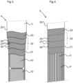
- Fig 3 discloses a tubular ceramic component 20 of a first embodiment according to which the tubular ceramic component 20 forms the cladding tube 11 of the fuel rod.
- the tubular ceramic component 20 comprises an inner layer 21, an intermediate layer 22 adjoining the inner layer 21, and an outer layer 23 adjoining the intermediate layer 22.
- Fig 4 discloses a tubular ceramic component 20 of a second embodiment according to which the tubular ceramic component 20 forms the flow channel 6 of the fuel assembly 1. Also in the second embodiment, the tubular ceramic component 20 comprises an inner layer 21, an intermediate layer 22 adjoining the inner layer 21, and an outer layer 23 adjoining the intermediate layer 22.
- the inner layer 21 consists of homogeneous, preferably monolithic, silicon carbide.
- the intermediate layer 22 consists of silicon carbide fibres 25, 26 in a fill material 27 of homogeneous silicon carbide.
- the outer layer 23 consists of homogeneous, preferably monolithic, silicon carbide.
- the silicon carbide fibres 25, 26 of the intermediate layer 22 are wound in two sublayers, wherein the silicon carbide fibres 25, 26 of the two layers run crosswise, i.e. the fibre direction of the silicon carbide fibres 26, 27 of the two sublayers crosses each other.
- intermediate layer 22 also may comprise only one sublayer with silicon carbide fibres 25, 26, or more than two sublayers with silicon carbide fibres 25, 26.
- the silicon carbide of the inner layer 21, of the fill material 27 and of the outer layer 23 is crystalline and doped with one or more dopants.
- the dopants are present in solid solution within crystals of the crystalline silicon carbide of the inner layer 21, of the fill material 27 and of the outer layer 23.
- the dopant, or dopants may be added to the silicon carbide in various ways.
- the dopants can be added during the process of depositing the silicon carbide onto the silicon carbide fibres 25, 26 and onto the intermediate layer 22.
- silicon carbide fibres 25, 26 may be wound in one or more sublayers to a tubular shape, for instance on a suitable form.
- silicon carbide may be deposited on the silicon fibres 25, 26 of the intermediate layer 22 to form the fill material 27.
- the silicon carbide will penetrate the interspaces between the silicon carbide fibres 25, 26.
- the silicon carbide may be deposited by any suitable method such as sputtering, physical vapour deposition, PVD, chemical vapour deposition, CVD, etc.
- the dopant may then be added in advance to the silicon carbide to be deposited, or be mixed with the silicon carbide during the depositing process.
- the silicon carbide may be deposited to the intermediate layer 22 to form the inner layer 21 onto the intermediate layer 22 by any of the depositing methods mentioned above.
- the dopant may then be added in the same way as to the silicon carbide of intermediate layer 22.
- the silicon carbide may be deposited to the intermediate layer 22 to form the outer layer 23 onto the intermediate layer 22 by any of the depositing methods mentioned above.
- the dopant may then be added in the same way as to the silicon carbide of intermediate layer 22.
- the outer layer 23 may be deposited after or before the deposition of the inner layer 21.
- the dopant or dopants may be supplied during the manufacturing of the silicon carbide, for instance by adding the dopant or dopants to SiO 2 and C in a so called Acheson furnace.
- the concentration of the dopants in the silicon carbide of the inner layer 21, of the fill material 27 and of the outer layer 23 may be 1-1000 ppm, preferably 10-1000 ppm, more preferably 50-1000 ppm, and most preferably 50-500 ppm.
- the silicon carbide of the inner layer 21, of the fill material 27 and of the outer layer 23 may contain a balance of possible residual substances in addition to the dopant or dopants.
- the silicon carbide of the inner layer 21, of the fill material 27 and of the outer layer 23 has a concentration of secondary phases that is less than 1 %.
- the silicon carbide fibres 25, 26 are made of pure, or substantially pure, silicon carbide being free of dopants. A balance of possible residual substances may be present in the silicon carbide fibres 25, 26.
- the dopants to be added to and comprised by the silicon carbide comprise at least one of the substances B, N, Al, P, O, Be, Li, S, Ti, Ge, P 2 O 3 , P 2 O 5 , Al 2 O 3 , AIN, and Al 4 C 3 .
- the silicon carbide may be doped by the addition of one of these substances, or with a combination of two or more of these substances.
- B is a possible dopant which may be contained in solid solution in crystals of the silicon carbide.
- the boron is enriched to contain a higher percentage of the isotope 11 B than natural B in order to reduce the neutron absorption cross-section.
- B may be added as an element, for instance by sputtering, PVD or CVD.
- N is a possible dopant which may be contained in solid solution in crystals of the silicon carbide.
- the nitrogen is enriched to contain a higher percentage of the isotope 15 N than natural N in order to reduce the neutron absorption cross-section.
- N may be added as an element, for instance by sputtering, PVD or CVD.
- the element N is larger than C, and thus N may be effective to replace C-atoms in the silicon carbide.
- Al is a possible dopant which may be contained in solid solution in crystals of the silicon carbide.
- Al may be added as an element, for instance by sputtering, PVD or CVD.
- Al may also be added as one of the compounds Al 2 O 3 , AIN and Al 4 C 3 . Also in these cases, Al will be contained as an element in solid solution in the crystals of the silicon carbide.
- the element Al is larger than C, and thus Al may be effective to replace C-atoms in the silicon carbide.
- P is a possible dopant which may be contained in solid solution in crystals of the silicon carbide.
- P may be added as an element, for instance by sputtering, PVD or CVD.
- P may also be added as one of the compounds P 2 O 3 and P 2 O 5 .
- P will be contained as an element in solid solution in the crystals of the silicon carbide.
- the element P is larger than C, and thus P may be effective to replace C-atoms in the silicon carbide.
- O is a possible dopant which may be contained in solid solution in crystals of the silicon carbide.
- O may be added as an element, for instance by sputtering, PVD or CVD.
- O may also be added as one of the compounds P 2 O 3 , P 2 O 5 and Al 2 O 3 .
- O will be contained as an element in solid solution in the crystals of the silicon carbide.
- the element O is larger than C, and thus O may be effective to replace C-atoms in the silicon carbide.
- Be is a possible dopant which may be contained in solid solution in crystals of the silicon carbide. Be may be added as an element, for instance by sputtering, PVD or CVD.
- Li is a possible dopant which may be contained in solid solution in crystals of the silicon carbide. Li may be added as an element, for instance by sputtering, PVD or CVD.
- S is a possible dopant which may be contained in solid solution in crystals of the silicon carbide.
- S may be added as an element, for instance by sputtering, PVD or CVD.
- the element S is larger than both C and Si, and thus S may be effective to replace C-atoms and Si-atoms in the silicon carbide.
- Ti is a possible dopant which may be contained in solid solution in crystals of the silicon carbide.
- Ti may be added as an element, for instance by sputtering, PVD or CVD.
- Ti may also be added as the compound TiC 1-x .
- Ti will be contained as an element in solid solution in the crystals of the silicon carbide.
- the element Ti is larger than both C and Si, and thus Ti may be effective to replace C-atoms and Si-atoms in the silicon carbide.
- Ge is a possible dopant which may be contained in solid solution in crystals of the silicon carbide. Ge may be added as an element, for instance by sputtering, PVD or CVD. The element Ge is larger than both C and Si, and thus Ge may be effective to replace C-atoms and Si-atoms in the silicon carbide.
Landscapes
- Engineering & Computer Science (AREA)
- Chemical & Material Sciences (AREA)
- Physics & Mathematics (AREA)
- Ceramic Engineering (AREA)
- Plasma & Fusion (AREA)
- High Energy & Nuclear Physics (AREA)
- General Engineering & Computer Science (AREA)
- Metallurgy (AREA)
- Materials Engineering (AREA)
- Structural Engineering (AREA)
- Organic Chemistry (AREA)
- Manufacturing & Machinery (AREA)
- Ceramic Products (AREA)
Description
- The present invention refers generally to doping of tubular ceramic SiC and SiC-SiC components, such as flow channels and cladding tubes in fuel assemblies, for nuclear reactors, especially water reactors, such as Boiling Water Reactors, BWR, and Pressurized Water Reactors, PWR. The invention could also be applicable to fast reactors, such as lead fast reactors.
- In particular, the present invention refers to a method of providing a tubular ceramic component for use in a nuclear reactor, comprising an inner layer of silicon carbide, an intermediate layer of silicon carbide fibres in a fill material of silicon carbide, the intermediate layer adjoining the inner layer, and an outer layer of silicon carbide, the outer layer adjoining the intermediate layer.
- It is known to use silicon carbide or silicon carbide composites in nuclear components, such as fuel assemblies and flow channels.
-
US 2006/0039524 discloses a multi-layered cladding tube comprising an inner layer of monolithic silicon carbide, a central layer of silicon carbide fibres surrounded by a silicon carbide matrix, and an outer layer of silicon carbide. -
WO 2011/134757 discloses a flow channel for a fuel assembly. - The flow channel comprises an inner layer of silicon carbide, a central layer of silicon carbide fibres surrounded by a filler material of silicon carbide, and an outer layer of silicon carbide.
-
US 2016/0049211 discloses a multi-layered silicon carbide cladding tube. -
WO 2011/134757 discloses a fuel channel arranged to be comprised by a fuel element for a fission reactor. -
EP 2899176 discloses a ceramic structure including silicon carbide, that includes carbon and silicon which has 28Si enriched in comparison with a natural abundance ratio. -
WO 2015/053937 discloses a method for providing crystalline silicon-containing ceramic material. -
US 2015/0247077 discloses adhesive composition and method to join non-oxide silicon based ceramic parts. -
JP H06 279119 -
US 2017/204532 relates to vapor deposition apparatus and techniques using high purity polymer derived silicon carbide. - Pure silicon carbide, or substantially pure silicon carbide, grows isotropically when exposed to irradiation and high temperatures. The growth is due to impurities (secondary phases) in the crystalline silicon carbide, and to the formation of defects in the crystalline silicon carbide.
- In a nuclear reactor, a relatively rapid growth of a silicon carbide component will occur during an initial phase up to a certain level which then remains relatively constant during the lifetime of the component. This is a problem in cladding tubes of silicon carbide. Since the fuel in the cladding tubes swells continuously during the lifetime of the fuel, it is difficult to maintain a constant pellet-cladding gap.
- The growth due to impurities may be avoided by securing a small amount of secondary phases, which may be possible by choosing a suitable manufacturing method.
- The growth due to the formation of defects occurs in the temperature interval 250-400°C through the formation of point defects, i.e. atoms of Si or C are moved to interstitial positions in the crystalline structure.
- The object of the present invention is to overcome the problems discussed above. In particular, the invention aims at a reduced and more uniform growth, or swelling, of the tubular ceramic component upon exposure to a neutron flux during operation in a nuclear reactor.
- This object is achieved by a method of providing the tubular ceramic component initially defined, which method is characterized in that the silicon carbide of the inner layer, the fill material and the outer layer is doped and comprises at least one dopant in solid solution within crystals of the silicon carbide, wherein the dopant or dopants will provide a pre- swelling or growth of the silicon carbide, before the operation of the tubular ceramic component in the nuclear reactor.
- The silicon carbide of the inner layer, the fill material and the outer layer may thus comprise pure crystalline silicon carbide, or substantially pure crystalline silicon carbide, with the dopant or dopants in solid solution in the silicon carbide crystals and with very small quantities of secondary phases, for instance less than 1% of secondary phases.
- By adding one or more dopants to the silicon carbide of the inner layer, the fill material and the outer layer, the growth of the cladding tube during operation in the nuclear reactor may be reduced and modified to be more uniform. Especially during the initial phase of the operation, the relatively rapid growth of non-doped silicon carbide components may be significantly reduced.
- The dopant or dopants will provide a pre-swelling or growth of the silicon carbide, before the operation of the tubular ceramic component in the nuclear reactor. The change in connectivity due to the presence of the dopant or dopants in solid solution in the crystal structure of the silicon carbide will mean that a population of defects will exist within the structure that will enhance mobility of certain defects and promote additional defects to recombine, preventing further swelling or growth.
- The dopant or dopants will provide a possibility to control the defect-related growth and the formation of point defects. The main part of the defect-related growth is due to the displacement of C-atoms. This displacement creates internal stresses and deformation. At sufficiently high internal stresses (which increase with reduced temperature), the growth stops (since new point defects are not any longer stable), i.e. the saturation growth is highest at low temperatures.
- According to an embodiment of the invention, the dopant comprises at least one of the substances B, N, Al, P, O, Be, Li, S, Ti, Ge, P2O3, P2O5, Al2O3, AIN, and Al4C3.
- Doping of the silicon carbide may thus be achieved by adding one or more of the elements B, N, Al, P, O, Be, Li, S, Ti, Ge, and/or one or more of the compounds P2O3, P2O5, Al2O3, AIN, and Al4C3 during the manufacturing of the tubular ceramic component.
- These dopants may have following properties making them suitable in the silicon carbide of the tubular ceramic component.
- Low neutron cross-section minimizing the absorption of neutrons.
- Larger size of the element than C increasing the formation of internal stresses. The smaller of the dopants may replace the C-atoms in the silicon carbide, whereas the larger of the elements, e.g. S and Ge, may replace the Si-atoms in the silicon carbide.
- Some of the dopants may replace both Si and C to different degrees.
- Strong repulsive interaction to interstitials leading to saturation at a lower degree of growth.
- According to an embodiment of the invention, the concentration of the dopant in the silicon carbide is 1-1000 ppm.
- According to an embodiment of the invention, the concentration of the dopant in the silicon carbide is 10-1000 ppm.
- According to an embodiment of the invention, the concentration of the dopant in the silicon carbide is 50-1000 ppm.
- According to an embodiment of the invention, the dopant comprises at least N, wherein the nitrogen is enriched to contain a higher percentage of the isotope 15N than natural N.
- According to an embodiment of the invention, the dopant comprises at least B, wherein the boron is enriched to contain a higher percentage of the isotope 11B than natural B.
- According to an embodiment of the invention, the silicon carbide of the inner layer, the fill material and the outer layer has a concentration of secondary phases that is less than 1%, preferably less than 0,8%, more preferably less than 0,6%, and most preferably less than 0,4%.
- According to an embodiment of the invention, the tubular ceramic component forms a cladding tube of a fuel rod and encloses a pile of nuclear fuel pellets.
- According to an embodiment of the invention, the tubular ceramic component forms flow channel of a fuel assembly and encloses a plurality of fuel rods.
- The invention is now to be explained more closely through a description of various embodiments and with reference to the drawings attached hereto.
- Fig 1
- discloses schematically a longitudinal sectional view of a fuel assembly for a nuclear reactor.
- Fig 2
- discloses schematically a longitudinal sectional view of a fuel rod of the fuel assembly in
Fig 1 . - Fig 3
- discloses schematically a partly sectional view of a part of the fuel rod in
Fig 2 . - Fig 4
- discloses schematically a partly sectional view of a part of the fuel assembly in
Fig 1 . -
Fig. 1 discloses a fuel assembly 1 for use in nuclear reactors, in particular in water cooled light water reactors, LWR, such as a Boiling Water Reactor, BWR, or a Pressurized Water reactor, PWR. The fuel assembly 1 comprises abottom member 2, atop member 3 and a plurality ofelongated fuel rods 4 extending between thebottom member 2 and thetop member 3. Thefuel rods 4 are maintained in their positions by means of a plurality ofspacers 5. - Furthermore, the fuel assembly 1 comprises, when intended to be used in a BWR, a
flow channel 6 that surrounds and encloses thefuel rods 4. -
Fig 2 discloses one of thefuel rods 4 of the fuel assembly 1 ofFig 1 . Thefuel rod 4 comprises a nuclear fuel in the form of a plurality of sinterednuclear fuel pellets 10, and acladding tube 11 enclosing thenuclear fuel pellets 10. Thefuel rod 4 comprises abottom plug 12 sealing a lower end of thecladding tube 11, and atop plug 13 sealing an upper end of thefuel rod 4. Thenuclear fuel pellets 10 are arranged in a pile in thecladding tube 11. Thecladding tube 11 thus encloses thefuel pellets 10 and a gas. Aspring 14 is arranged in anupper plenum 15 between the pile ofnuclear fuel pellets 10 and thetop plug 13. Thespring 14 presses the pile ofnuclear fuel pellets 10 against thebottom plug 12. -
Fig 3 discloses a tubularceramic component 20 of a first embodiment according to which the tubularceramic component 20 forms thecladding tube 11 of the fuel rod. The tubularceramic component 20 comprises aninner layer 21, anintermediate layer 22 adjoining theinner layer 21, and anouter layer 23 adjoining theintermediate layer 22. -
Fig 4 discloses a tubularceramic component 20 of a second embodiment according to which the tubularceramic component 20 forms theflow channel 6 of the fuel assembly 1. Also in the second embodiment, the tubularceramic component 20 comprises aninner layer 21, anintermediate layer 22 adjoining theinner layer 21, and anouter layer 23 adjoining theintermediate layer 22. - The
inner layer 21 consists of homogeneous, preferably monolithic, silicon carbide. Theintermediate layer 22 consists ofsilicon carbide fibres fill material 27 of homogeneous silicon carbide. Theouter layer 23 consists of homogeneous, preferably monolithic, silicon carbide. - As can be seen in
Fig 3 , thesilicon carbide fibres intermediate layer 22 are wound in two sublayers, wherein thesilicon carbide fibres silicon carbide fibres - It should be noted that the
intermediate layer 22 also may comprise only one sublayer withsilicon carbide fibres silicon carbide fibres - The silicon carbide of the
inner layer 21, of thefill material 27 and of theouter layer 23 is crystalline and doped with one or more dopants. - The dopants are present in solid solution within crystals of the crystalline silicon carbide of the
inner layer 21, of thefill material 27 and of theouter layer 23. - The dopant, or dopants, may be added to the silicon carbide in various ways. For instance the dopants can be added during the process of depositing the silicon carbide onto the
silicon carbide fibres intermediate layer 22. - In a first step,
silicon carbide fibres - In a second step, silicon carbide may be deposited on the
silicon fibres intermediate layer 22 to form thefill material 27. During the deposition process, the silicon carbide will penetrate the interspaces between thesilicon carbide fibres - In a third step, the silicon carbide may be deposited to the
intermediate layer 22 to form theinner layer 21 onto theintermediate layer 22 by any of the depositing methods mentioned above. The dopant may then be added in the same way as to the silicon carbide ofintermediate layer 22. - In a fourth step, the silicon carbide may be deposited to the
intermediate layer 22 to form theouter layer 23 onto theintermediate layer 22 by any of the depositing methods mentioned above. The dopant may then be added in the same way as to the silicon carbide ofintermediate layer 22. Theouter layer 23 may be deposited after or before the deposition of theinner layer 21. - According to another method, the dopant or dopants may be supplied during the manufacturing of the silicon carbide, for instance by adding the dopant or dopants to SiO2 and C in a so called Acheson furnace.
- The concentration of the dopants in the silicon carbide of the
inner layer 21, of thefill material 27 and of theouter layer 23 may be 1-1000 ppm, preferably 10-1000 ppm, more preferably 50-1000 ppm, and most preferably 50-500 ppm. - The silicon carbide of the
inner layer 21, of thefill material 27 and of theouter layer 23 may contain a balance of possible residual substances in addition to the dopant or dopants. - The silicon carbide of the
inner layer 21, of thefill material 27 and of theouter layer 23 has a concentration of secondary phases that is less than 1 %. - The
silicon carbide fibres silicon carbide fibres - The dopants to be added to and comprised by the silicon carbide comprise at least one of the substances B, N, Al, P, O, Be, Li, S, Ti, Ge, P2O3, P2O5, Al2O3, AIN, and Al4C3.
- The silicon carbide may be doped by the addition of one of these substances, or with a combination of two or more of these substances.
- B is a possible dopant which may be contained in solid solution in crystals of the silicon carbide. Preferably, the boron is enriched to contain a higher percentage of the isotope 11B than natural B in order to reduce the neutron absorption cross-section. B may be added as an element, for instance by sputtering, PVD or CVD.
- N is a possible dopant which may be contained in solid solution in crystals of the silicon carbide. Preferably, the nitrogen is enriched to contain a higher percentage of the isotope 15N than natural N in order to reduce the neutron absorption cross-section. N may be added as an element, for instance by sputtering, PVD or CVD. The element N is larger than C, and thus N may be effective to replace C-atoms in the silicon carbide.
- Al is a possible dopant which may be contained in solid solution in crystals of the silicon carbide. Al may be added as an element, for instance by sputtering, PVD or CVD. Al may also be added as one of the compounds Al2O3, AIN and Al4C3. Also in these cases, Al will be contained as an element in solid solution in the crystals of the silicon carbide. The element Al is larger than C, and thus Al may be effective to replace C-atoms in the silicon carbide.
- P is a possible dopant which may be contained in solid solution in crystals of the silicon carbide. P may be added as an element, for instance by sputtering, PVD or CVD. P may also be added as one of the compounds P2O3 and P2O5. Also in these cases, P will be contained as an element in solid solution in the crystals of the silicon carbide. The element P is larger than C, and thus P may be effective to replace C-atoms in the silicon carbide.
- O is a possible dopant which may be contained in solid solution in crystals of the silicon carbide. O may be added as an element, for instance by sputtering, PVD or CVD. O may also be added as one of the compounds P2O3, P2O5 and Al2O3. Also in these cases, O will be contained as an element in solid solution in the crystals of the silicon carbide. The element O is larger than C, and thus O may be effective to replace C-atoms in the silicon carbide.
- Be is a possible dopant which may be contained in solid solution in crystals of the silicon carbide. Be may be added as an element, for instance by sputtering, PVD or CVD.
- Li is a possible dopant which may be contained in solid solution in crystals of the silicon carbide. Li may be added as an element, for instance by sputtering, PVD or CVD.
- S is a possible dopant which may be contained in solid solution in crystals of the silicon carbide. S may be added as an element, for instance by sputtering, PVD or CVD. The element S is larger than both C and Si, and thus S may be effective to replace C-atoms and Si-atoms in the silicon carbide.
- Ti is a possible dopant which may be contained in solid solution in crystals of the silicon carbide. Ti may be added as an element, for instance by sputtering, PVD or CVD. Ti may also be added as the compound TiC1-x. Also in this case, Ti will be contained as an element in solid solution in the crystals of the silicon carbide. The element Ti is larger than both C and Si, and thus Ti may be effective to replace C-atoms and Si-atoms in the silicon carbide.
- Ge is a possible dopant which may be contained in solid solution in crystals of the silicon carbide. Ge may be added as an element, for instance by sputtering, PVD or CVD. The element Ge is larger than both C and Si, and thus Ge may be effective to replace C-atoms and Si-atoms in the silicon carbide.
- The present invention is not limited to the embodiments disclosed and discussed above, but may be varied and modified within the scope of the following claims.
Claims (10)
- A method of providing a tubular ceramic component (20) for use in a nuclear reactor, the tubular ceramic component (20) comprises:an inner layer (21) of silicon carbide,an intermediate layer (22) of silicon carbide fibres (25, 26) in a fill material (27) of silicon carbide, the intermediate layer (22) adjoining the inner layer (21), andan outer layer (23) of silicon carbide, the outer layer (23) adjoining the intermediate layer (22),characterized in that the method comprises doping the silicon carbide of the inner layer (21), the fill material and the outer layer (23) with a dopant comprising at least one dopant in solid solution within crystals of the silicon carbide, wherein the dopant or dopants will provide a pre-swelling or growth of the silicon carbide, before the operation of the tubular ceramic component in the nuclear reactor.
- The method according to claim 1, wherein the dopant comprises at least one of the substances B, N, Al, P, O, Be, Li, S, Ti, Ge, P2O3, P2O5, Al2O3, AIN, and Al4C3.
- The method according to any one of claims 1 and 2, wherein the concentration of the dopant in the silicon carbide is 1-1000 ppm.
- The method according to any one of claims 1 and 2, wherein the concentration of the dopant in the silicon carbide is 10-1000 ppm.
- The method according to any one of claims 1 and 2, wherein the concentration of the dopant in the silicon carbide is 50-1000 ppm.
- The method according to any one of the preceding claims, wherein the dopant comprises at least N, wherein the nitrogen is enriched to contain a higher percentage of the isotope 15N than natural N.
- The method according to any one of the preceding claims, wherein, the dopant comprises at least B, wherein the boron is enriched to contain a higher percentage of the isotope 11B than natural B.
- The method according to any one of the preceding claims, wherein the silicon carbide of the inner layer, the fill material and the outer layer has a concentration of secondary phases that is less than 1%.
- The method according to any one of the preceding claims, wherein the tubular ceramic component (20) forms a cladding tube (11) of a fuel rod (4) and encloses a pile of nuclear fuel pellets (10).
- The method according to any one of the preceding claims, wherein the tubular ceramic component (20) forms flow channel (6) of a fuel assembly and (1) encloses a plurality of fuel rods (4).
Applications Claiming Priority (2)
| Application Number | Priority Date | Filing Date | Title |
|---|---|---|---|
| US201862624420P | 2018-01-31 | 2018-01-31 | |
| PCT/EP2018/065343 WO2019149386A1 (en) | 2018-01-31 | 2018-06-11 | A tubular ceramic component suitable for being used in a nuclear reactor |
Publications (3)
| Publication Number | Publication Date |
|---|---|
| EP3738127A1 EP3738127A1 (en) | 2020-11-18 |
| EP3738127C0 EP3738127C0 (en) | 2024-07-24 |
| EP3738127B1 true EP3738127B1 (en) | 2024-07-24 |
Family
ID=62631075
Family Applications (1)
| Application Number | Title | Priority Date | Filing Date |
|---|---|---|---|
| EP18731784.7A Active EP3738127B1 (en) | 2018-01-31 | 2018-06-11 | Method of providing a tubular ceramic component for use in a nuclear reactor |
Country Status (4)
| Country | Link |
|---|---|
| US (1) | US20200373022A1 (en) |
| EP (1) | EP3738127B1 (en) |
| JP (1) | JP7122383B2 (en) |
| WO (1) | WO2019149386A1 (en) |
Families Citing this family (2)
| Publication number | Priority date | Publication date | Assignee | Title |
|---|---|---|---|---|
| ES3061193T3 (en) * | 2020-05-01 | 2026-03-31 | Westinghouse Electric Co Llc | Channel boxes for a boiling water reactor and methods of manufacture thereof |
| US11728048B2 (en) * | 2020-12-01 | 2023-08-15 | Westinghouse Electric Company Llc | Nuclear fuel rods and heat pipes in a graphite moderator matrix for a micro-reactor, with the fuel rods having fuel pellets in a BeO sleeve |
Citations (1)
| Publication number | Priority date | Publication date | Assignee | Title |
|---|---|---|---|---|
| US20170204532A1 (en) * | 2014-09-25 | 2017-07-20 | Melior Innovations, Inc. | Vapor deposition apparatus and techniques using high puritiy polymer derived silicon carbide |
Family Cites Families (8)
| Publication number | Priority date | Publication date | Assignee | Title |
|---|---|---|---|---|
| JPH06279119A (en) * | 1993-03-26 | 1994-10-04 | Hitachi Ltd | High thermal conductive SiC ceramics and manufacturing method thereof |
| US20060039524A1 (en) * | 2004-06-07 | 2006-02-23 | Herbert Feinroth | Multi-layered ceramic tube for fuel containment barrier and other applications in nuclear and fossil power plants |
| US7700202B2 (en) * | 2006-02-16 | 2010-04-20 | Alliant Techsystems Inc. | Precursor formulation of a silicon carbide material |
| US20110268243A1 (en) | 2010-04-28 | 2011-11-03 | Lars Hallstadius | Fuel channel arranged to be comprised by a fuel element for a fission reactor |
| US20150247077A1 (en) * | 2011-01-26 | 2015-09-03 | Thor Technologies, Inc. | Adhesive Composition and Method to Join Non-Oxide Silicon Based Ceramic Parts |
| US20160049211A1 (en) * | 2012-12-20 | 2016-02-18 | Ceramic Tubular Products, LLC | Silicon carbide multilayered cladding and nuclear reactor fuel element for use in water-cooled nuclear power reactors |
| EP3055270B1 (en) * | 2013-10-08 | 2021-02-17 | United Technologies Corporation | Method for providing crystalline silicon-containing ceramic material |
| JP6408221B2 (en) * | 2014-01-24 | 2018-10-17 | イビデン株式会社 | Reactor components |
-
2018
- 2018-06-11 US US16/962,330 patent/US20200373022A1/en not_active Abandoned
- 2018-06-11 WO PCT/EP2018/065343 patent/WO2019149386A1/en not_active Ceased
- 2018-06-11 EP EP18731784.7A patent/EP3738127B1/en active Active
- 2018-06-11 JP JP2020541875A patent/JP7122383B2/en active Active
Patent Citations (1)
| Publication number | Priority date | Publication date | Assignee | Title |
|---|---|---|---|---|
| US20170204532A1 (en) * | 2014-09-25 | 2017-07-20 | Melior Innovations, Inc. | Vapor deposition apparatus and techniques using high puritiy polymer derived silicon carbide |
Also Published As
| Publication number | Publication date |
|---|---|
| JP7122383B2 (en) | 2022-08-19 |
| JP2021513063A (en) | 2021-05-20 |
| US20200373022A1 (en) | 2020-11-26 |
| EP3738127C0 (en) | 2024-07-24 |
| EP3738127A1 (en) | 2020-11-18 |
| WO2019149386A1 (en) | 2019-08-08 |
Similar Documents
| Publication | Publication Date | Title |
|---|---|---|
| US11518719B2 (en) | Additive manufacturing technique for placing nuclear reactor fuel within fibers | |
| US8697024B2 (en) | Method of forming a silicon carbide material, and structures including the material | |
| RU2504030C2 (en) | Nuclear fuel shell with high specific heat conductivity and method of its production | |
| US11362256B2 (en) | Functional high-performance fiber structure | |
| US5265137A (en) | Wear resistant nuclear fuel assembly components | |
| KR102864950B1 (en) | Coatings and surface modifications to mitigate SiC cladding during operation of light water reactors. | |
| CA3130500A1 (en) | Modified polymer derived ceramics for additive manufacturing, additive manufacturing using same, and ceramic bodies manufactured thereby | |
| US20200373022A1 (en) | A tubular ceramic component suitable for being used in a nuclear reactor | |
| KR20200088294A (en) | High temperature ceramic fuel system for light water reactor and lead high speed reactor | |
| WO2018197105A1 (en) | A ceramic nuclear fuel pellet, a fuel rod, and a fuel assembly | |
| KR102102977B1 (en) | Method of manufacturing nuclear fuel pellet consisting of duplex grains | |
| NO155046B (en) | ROLL PACKAGE DEVICE. | |
| EP2899176A1 (en) | Ceramic structure | |
| KR20260032924A (en) | Self-healing liquid pellet-cladding gap heat transfer filler | |
| US7485246B2 (en) | Fabrication method of sintered duplex nuclear fuel pellet | |
| WO2008080304A1 (en) | Crystal producing system containing multiple crucibles used in temperature gradient method | |
| JP6632931B2 (en) | Structural member and manufacturing method thereof, fuel rod, fuel channel box, water rod, fuel assembly | |
| Li et al. | Innovative accident tolerant fuel concept enabled through direct manufacturing technology | |
| US3207697A (en) | High-temperature nuclear fuel structures and their production | |
| EP3924980A2 (en) | Sintering with sps/fast uranium fuel with or without burnable absorbers | |
| RU2328783C1 (en) | Coated fuel particle of nuclear reactor | |
| WO2019166111A1 (en) | A fuel element containing uranium silicide and suitable for a nuclear reactor | |
| US3728220A (en) | Nuclear reactor fuel pins | |
| RU2603020C1 (en) | Method of making nuclear reactor pebbles | |
| RU2369925C1 (en) | Coated fuel particle for nuclear reactor |
Legal Events
| Date | Code | Title | Description |
|---|---|---|---|
| STAA | Information on the status of an ep patent application or granted ep patent |
Free format text: STATUS: UNKNOWN |
|
| STAA | Information on the status of an ep patent application or granted ep patent |
Free format text: STATUS: THE INTERNATIONAL PUBLICATION HAS BEEN MADE |
|
| PUAI | Public reference made under article 153(3) epc to a published international application that has entered the european phase |
Free format text: ORIGINAL CODE: 0009012 |
|
| STAA | Information on the status of an ep patent application or granted ep patent |
Free format text: STATUS: REQUEST FOR EXAMINATION WAS MADE |
|
| 17P | Request for examination filed |
Effective date: 20200615 |
|
| AK | Designated contracting states |
Kind code of ref document: A1 Designated state(s): AL AT BE BG CH CY CZ DE DK EE ES FI FR GB GR HR HU IE IS IT LI LT LU LV MC MK MT NL NO PL PT RO RS SE SI SK SM TR |
|
| AX | Request for extension of the european patent |
Extension state: BA ME |
|
| DAV | Request for validation of the european patent (deleted) | ||
| DAX | Request for extension of the european patent (deleted) | ||
| STAA | Information on the status of an ep patent application or granted ep patent |
Free format text: STATUS: EXAMINATION IS IN PROGRESS |
|
| 17Q | First examination report despatched |
Effective date: 20230630 |
|
| GRAP | Despatch of communication of intention to grant a patent |
Free format text: ORIGINAL CODE: EPIDOSNIGR1 |
|
| STAA | Information on the status of an ep patent application or granted ep patent |
Free format text: STATUS: GRANT OF PATENT IS INTENDED |
|
| INTG | Intention to grant announced |
Effective date: 20240221 |
|
| GRAS | Grant fee paid |
Free format text: ORIGINAL CODE: EPIDOSNIGR3 |
|
| GRAA | (expected) grant |
Free format text: ORIGINAL CODE: 0009210 |
|
| STAA | Information on the status of an ep patent application or granted ep patent |
Free format text: STATUS: THE PATENT HAS BEEN GRANTED |
|
| AK | Designated contracting states |
Kind code of ref document: B1 Designated state(s): AL AT BE BG CH CY CZ DE DK EE ES FI FR GB GR HR HU IE IS IT LI LT LU LV MC MK MT NL NO PL PT RO RS SE SI SK SM TR |
|
| REG | Reference to a national code |
Ref country code: GB Ref legal event code: FG4D |
|
| REG | Reference to a national code |
Ref country code: CH Ref legal event code: EP |
|
| REG | Reference to a national code |
Ref country code: DE Ref legal event code: R096 Ref document number: 602018072162 Country of ref document: DE |
|
| REG | Reference to a national code |
Ref country code: IE Ref legal event code: FG4D |
|
| U01 | Request for unitary effect filed |
Effective date: 20240807 |
|
| U07 | Unitary effect registered |
Designated state(s): AT BE BG DE DK EE FI FR IT LT LU LV MT NL PT SE SI Effective date: 20240823 |
|
| PG25 | Lapsed in a contracting state [announced via postgrant information from national office to epo] |
Ref country code: NO Free format text: LAPSE BECAUSE OF FAILURE TO SUBMIT A TRANSLATION OF THE DESCRIPTION OR TO PAY THE FEE WITHIN THE PRESCRIBED TIME-LIMIT Effective date: 20241024 |
|
| PG25 | Lapsed in a contracting state [announced via postgrant information from national office to epo] |
Ref country code: GR Free format text: LAPSE BECAUSE OF FAILURE TO SUBMIT A TRANSLATION OF THE DESCRIPTION OR TO PAY THE FEE WITHIN THE PRESCRIBED TIME-LIMIT Effective date: 20241025 Ref country code: PL Free format text: LAPSE BECAUSE OF FAILURE TO SUBMIT A TRANSLATION OF THE DESCRIPTION OR TO PAY THE FEE WITHIN THE PRESCRIBED TIME-LIMIT Effective date: 20240724 |
|
| PG25 | Lapsed in a contracting state [announced via postgrant information from national office to epo] |
Ref country code: IS Free format text: LAPSE BECAUSE OF FAILURE TO SUBMIT A TRANSLATION OF THE DESCRIPTION OR TO PAY THE FEE WITHIN THE PRESCRIBED TIME-LIMIT Effective date: 20241124 |
|
| PG25 | Lapsed in a contracting state [announced via postgrant information from national office to epo] |
Ref country code: HR Free format text: LAPSE BECAUSE OF FAILURE TO SUBMIT A TRANSLATION OF THE DESCRIPTION OR TO PAY THE FEE WITHIN THE PRESCRIBED TIME-LIMIT Effective date: 20240724 |
|
| PG25 | Lapsed in a contracting state [announced via postgrant information from national office to epo] |
Ref country code: ES Free format text: LAPSE BECAUSE OF FAILURE TO SUBMIT A TRANSLATION OF THE DESCRIPTION OR TO PAY THE FEE WITHIN THE PRESCRIBED TIME-LIMIT Effective date: 20240724 Ref country code: RS Free format text: LAPSE BECAUSE OF FAILURE TO SUBMIT A TRANSLATION OF THE DESCRIPTION OR TO PAY THE FEE WITHIN THE PRESCRIBED TIME-LIMIT Effective date: 20241024 |
|
| PG25 | Lapsed in a contracting state [announced via postgrant information from national office to epo] |
Ref country code: RS Free format text: LAPSE BECAUSE OF FAILURE TO SUBMIT A TRANSLATION OF THE DESCRIPTION OR TO PAY THE FEE WITHIN THE PRESCRIBED TIME-LIMIT Effective date: 20241024 Ref country code: PL Free format text: LAPSE BECAUSE OF FAILURE TO SUBMIT A TRANSLATION OF THE DESCRIPTION OR TO PAY THE FEE WITHIN THE PRESCRIBED TIME-LIMIT Effective date: 20240724 Ref country code: NO Free format text: LAPSE BECAUSE OF FAILURE TO SUBMIT A TRANSLATION OF THE DESCRIPTION OR TO PAY THE FEE WITHIN THE PRESCRIBED TIME-LIMIT Effective date: 20241024 Ref country code: IS Free format text: LAPSE BECAUSE OF FAILURE TO SUBMIT A TRANSLATION OF THE DESCRIPTION OR TO PAY THE FEE WITHIN THE PRESCRIBED TIME-LIMIT Effective date: 20241124 Ref country code: HR Free format text: LAPSE BECAUSE OF FAILURE TO SUBMIT A TRANSLATION OF THE DESCRIPTION OR TO PAY THE FEE WITHIN THE PRESCRIBED TIME-LIMIT Effective date: 20240724 Ref country code: GR Free format text: LAPSE BECAUSE OF FAILURE TO SUBMIT A TRANSLATION OF THE DESCRIPTION OR TO PAY THE FEE WITHIN THE PRESCRIBED TIME-LIMIT Effective date: 20241025 Ref country code: ES Free format text: LAPSE BECAUSE OF FAILURE TO SUBMIT A TRANSLATION OF THE DESCRIPTION OR TO PAY THE FEE WITHIN THE PRESCRIBED TIME-LIMIT Effective date: 20240724 |
|
| PG25 | Lapsed in a contracting state [announced via postgrant information from national office to epo] |
Ref country code: RO Free format text: LAPSE BECAUSE OF FAILURE TO SUBMIT A TRANSLATION OF THE DESCRIPTION OR TO PAY THE FEE WITHIN THE PRESCRIBED TIME-LIMIT Effective date: 20240724 Ref country code: SM Free format text: LAPSE BECAUSE OF FAILURE TO SUBMIT A TRANSLATION OF THE DESCRIPTION OR TO PAY THE FEE WITHIN THE PRESCRIBED TIME-LIMIT Effective date: 20240724 |
|
| PG25 | Lapsed in a contracting state [announced via postgrant information from national office to epo] |
Ref country code: CZ Free format text: LAPSE BECAUSE OF FAILURE TO SUBMIT A TRANSLATION OF THE DESCRIPTION OR TO PAY THE FEE WITHIN THE PRESCRIBED TIME-LIMIT Effective date: 20240724 |
|
| PG25 | Lapsed in a contracting state [announced via postgrant information from national office to epo] |
Ref country code: SK Free format text: LAPSE BECAUSE OF FAILURE TO SUBMIT A TRANSLATION OF THE DESCRIPTION OR TO PAY THE FEE WITHIN THE PRESCRIBED TIME-LIMIT Effective date: 20240724 |
|
| PLBE | No opposition filed within time limit |
Free format text: ORIGINAL CODE: 0009261 |
|
| STAA | Information on the status of an ep patent application or granted ep patent |
Free format text: STATUS: NO OPPOSITION FILED WITHIN TIME LIMIT |
|
| 26N | No opposition filed |
Effective date: 20250425 |
|
| U20 | Renewal fee for the european patent with unitary effect paid |
Year of fee payment: 8 Effective date: 20250617 |
|
| REG | Reference to a national code |
Ref country code: CH Ref legal event code: H13 Free format text: ST27 STATUS EVENT CODE: U-0-0-H10-H13 (AS PROVIDED BY THE NATIONAL OFFICE) Effective date: 20260127 |
|
| PG25 | Lapsed in a contracting state [announced via postgrant information from national office to epo] |
Ref country code: MC Free format text: LAPSE BECAUSE OF FAILURE TO SUBMIT A TRANSLATION OF THE DESCRIPTION OR TO PAY THE FEE WITHIN THE PRESCRIBED TIME-LIMIT Effective date: 20240724 |
|
| GBPC | Gb: european patent ceased through non-payment of renewal fee |
Effective date: 20250611 |
|
| PG25 | Lapsed in a contracting state [announced via postgrant information from national office to epo] |
Ref country code: GB Free format text: LAPSE BECAUSE OF NON-PAYMENT OF DUE FEES Effective date: 20250611 |
|
| PG25 | Lapsed in a contracting state [announced via postgrant information from national office to epo] |
Ref country code: IE Free format text: LAPSE BECAUSE OF NON-PAYMENT OF DUE FEES Effective date: 20250611 |
|
| PG25 | Lapsed in a contracting state [announced via postgrant information from national office to epo] |
Ref country code: CH Free format text: LAPSE BECAUSE OF NON-PAYMENT OF DUE FEES Effective date: 20250630 |