EP3737985B1 - Gleitsichtvorrichtungen, systeme und verfahren unter verwendung einer verformbaren gestuften linse - Google Patents
Gleitsichtvorrichtungen, systeme und verfahren unter verwendung einer verformbaren gestuften linse Download PDFInfo
- Publication number
- EP3737985B1 EP3737985B1 EP18898491.8A EP18898491A EP3737985B1 EP 3737985 B1 EP3737985 B1 EP 3737985B1 EP 18898491 A EP18898491 A EP 18898491A EP 3737985 B1 EP3737985 B1 EP 3737985B1
- Authority
- EP
- European Patent Office
- Prior art keywords
- stepped lens
- deformable stepped
- force
- deformable
- lens
- Prior art date
- Legal status (The legal status is an assumption and is not a legal conclusion. Google has not performed a legal analysis and makes no representation as to the accuracy of the status listed.)
- Active
Links
Images


Classifications
-
- G—PHYSICS
- G02—OPTICS
- G02B—OPTICAL ELEMENTS, SYSTEMS OR APPARATUS
- G02B3/00—Simple or compound lenses
- G02B3/02—Simple or compound lenses with non-spherical faces
- G02B3/08—Simple or compound lenses with non-spherical faces with discontinuous faces, e.g. Fresnel lens
-
- F—MECHANICAL ENGINEERING; LIGHTING; HEATING; WEAPONS; BLASTING
- F03—MACHINES OR ENGINES FOR LIQUIDS; WIND, SPRING, OR WEIGHT MOTORS; PRODUCING MECHANICAL POWER OR A REACTIVE PROPULSIVE THRUST, NOT OTHERWISE PROVIDED FOR
- F03G—SPRING, WEIGHT, INERTIA OR LIKE MOTORS; MECHANICAL-POWER PRODUCING DEVICES OR MECHANISMS, NOT OTHERWISE PROVIDED FOR OR USING ENERGY SOURCES NOT OTHERWISE PROVIDED FOR
- F03G7/00—Mechanical-power-producing mechanisms, not otherwise provided for or using energy sources not otherwise provided for
- F03G7/008—Mechanical-power-producing mechanisms, not otherwise provided for or using energy sources not otherwise provided for characterised by the actuating element
- F03G7/012—Electro-chemical actuators
- F03G7/0121—Electroactive polymers
-
- F—MECHANICAL ENGINEERING; LIGHTING; HEATING; WEAPONS; BLASTING
- F03—MACHINES OR ENGINES FOR LIQUIDS; WIND, SPRING, OR WEIGHT MOTORS; PRODUCING MECHANICAL POWER OR A REACTIVE PROPULSIVE THRUST, NOT OTHERWISE PROVIDED FOR
- F03G—SPRING, WEIGHT, INERTIA OR LIKE MOTORS; MECHANICAL-POWER PRODUCING DEVICES OR MECHANISMS, NOT OTHERWISE PROVIDED FOR OR USING ENERGY SOURCES NOT OTHERWISE PROVIDED FOR
- F03G7/00—Mechanical-power-producing mechanisms, not otherwise provided for or using energy sources not otherwise provided for
- F03G7/06—Mechanical-power-producing mechanisms, not otherwise provided for or using energy sources not otherwise provided for using expansion or contraction of bodies due to heating, cooling, moistening, drying or the like
- F03G7/061—Mechanical-power-producing mechanisms, not otherwise provided for or using energy sources not otherwise provided for using expansion or contraction of bodies due to heating, cooling, moistening, drying or the like characterised by the actuating element
- F03G7/0614—Mechanical-power-producing mechanisms, not otherwise provided for or using energy sources not otherwise provided for using expansion or contraction of bodies due to heating, cooling, moistening, drying or the like characterised by the actuating element using shape memory elements
- F03G7/06143—Wires
-
- G—PHYSICS
- G02—OPTICS
- G02B—OPTICAL ELEMENTS, SYSTEMS OR APPARATUS
- G02B26/00—Optical devices or arrangements for the control of light using movable or deformable optical elements
- G02B26/08—Optical devices or arrangements for the control of light using movable or deformable optical elements for controlling the direction of light
- G02B26/0875—Optical devices or arrangements for the control of light using movable or deformable optical elements for controlling the direction of light by means of one or more refracting elements
-
- G—PHYSICS
- G02—OPTICS
- G02B—OPTICAL ELEMENTS, SYSTEMS OR APPARATUS
- G02B27/00—Optical systems or apparatus not provided for by any of the groups G02B1/00 - G02B26/00, G02B30/00
- G02B27/0093—Optical systems or apparatus not provided for by any of the groups G02B1/00 - G02B26/00, G02B30/00 with means for monitoring data relating to the user, e.g. head-tracking, eye-tracking
-
- G—PHYSICS
- G02—OPTICS
- G02B—OPTICAL ELEMENTS, SYSTEMS OR APPARATUS
- G02B27/00—Optical systems or apparatus not provided for by any of the groups G02B1/00 - G02B26/00, G02B30/00
- G02B27/01—Head-up displays
- G02B27/017—Head mounted
- G02B27/0172—Head mounted characterised by optical features
-
- G—PHYSICS
- G02—OPTICS
- G02B—OPTICAL ELEMENTS, SYSTEMS OR APPARATUS
- G02B3/00—Simple or compound lenses
- G02B3/12—Fluid-filled or evacuated lenses
- G02B3/14—Fluid-filled or evacuated lenses of variable focal length
-
- G—PHYSICS
- G02—OPTICS
- G02C—SPECTACLES; SUNGLASSES OR GOGGLES INSOFAR AS THEY HAVE THE SAME FEATURES AS SPECTACLES; CONTACT LENSES
- G02C7/00—Optical parts
- G02C7/02—Lenses; Lens systems ; Methods of designing lenses
- G02C7/08—Auxiliary lenses; Arrangements for varying focal length
- G02C7/081—Ophthalmic lenses with variable focal length
-
- G—PHYSICS
- G02—OPTICS
- G02B—OPTICAL ELEMENTS, SYSTEMS OR APPARATUS
- G02B27/00—Optical systems or apparatus not provided for by any of the groups G02B1/00 - G02B26/00, G02B30/00
- G02B27/01—Head-up displays
- G02B27/0179—Display position adjusting means not related to the information to be displayed
- G02B2027/0181—Adaptation to the pilot/driver
-
- G—PHYSICS
- G02—OPTICS
- G02B—OPTICAL ELEMENTS, SYSTEMS OR APPARATUS
- G02B27/00—Optical systems or apparatus not provided for by any of the groups G02B1/00 - G02B26/00, G02B30/00
- G02B27/01—Head-up displays
- G02B27/0179—Display position adjusting means not related to the information to be displayed
- G02B2027/0185—Displaying image at variable distance
-
- G—PHYSICS
- G02—OPTICS
- G02C—SPECTACLES; SUNGLASSES OR GOGGLES INSOFAR AS THEY HAVE THE SAME FEATURES AS SPECTACLES; CONTACT LENSES
- G02C2202/00—Generic optical aspects applicable to one or more of the subgroups of G02C7/00
- G02C2202/20—Diffractive and Fresnel lenses or lens portions
Definitions
- HMD headmounted display
- distances between the eye of the viewer and the display, distances between the display or the eye and one or more lenses or other optical components, or distances between individual optical components may be altered over time to mimic the varying distances of virtual objects from the viewer by causing the eye of the viewer to focus on the virtual object (e.g., by shaping of the human lens, by contracting or dilating the human pupil, and so on) in a manner similar to that in the real world.
- Such systems may require a significant level of power and space to implement within an HMD system or other optical device.
- the present disclosure is generally directed to varifocal apparatuses, systems, and methods employing a deformable stepped lens.
- an actuator to apply at least one force to deform the lens (e.g., by applying radial force to one or more locations along a perimeter of the lens toward the center of the lens)
- the shape of the lens may be altered from one state to another, thus altering the optical power and/or focal length of the lens.
- embodiments of the instant disclosure may facilitate a low-power, low-volume varifocal system that may be implemented in a virtual reality display system, such as an HMD.
- FIGS. 1-12 detailed descriptions of varifocal apparatuses, systems, and methods that may include a deformable stepped lens.
- An exemplary apparatus including such a lens is discussed in conjunction with FIG. 1 .
- a description of a deformable stepped lens to which a force may be applied to the deformable stepped lens to alter its shape, and thus its optical power, is presented in connection with FIGS. 2-4 .
- An exemplary HMD is presented in reference to FIG. 5 . and an exemplary display system that includes a deformable stepped lens employable in the exemplary HMD of FIG. 5 is discussed in connection with FIG. 6 .
- FIGS. 7-9 Various embodiments of a varifocal apparatus that may include a deformable stepped lens are discussed with reference to FIGS. 7-9 .
- a description of an exemplary system that may employ a varifocal system that includes a deformable stepped lens is presented in conjunction with FIG. 10 .
- a method of varifocal operation that may employ a deformable stepped lens is presented in reference to FIG. 11
- a method of providing a varifocal system that may include such a lens is provided in connection with FIG. 12 .
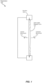
- FIG. 1 is a cross-sectional view of an exemplary varifocal apparatus 100 employing a deformable stepped lens 102.
- a deformable stepped lens may be any deformable (e.g., bendable, twistable, or otherwise flexible) lens that employs a stepped (e.g., discontinuous) surface on at least one side of the lens to provide an optical power similar to that of a thicker lens having a continuous surface on both sides of the lens.
- a deformable stepped lens may be a deformable Fresnel lens, such as a Fresnel lens with a stepped surface that mimics the operation of a convex lens surface.
- deformable stepped lens 102 may have a first side that is substantially flat and a second side opposite the first side that includes a plurality of concentric ridges or steps, such as that often seen in a Fresnel lens.
- deformable stepped lenses may be employed in other embodiments.
- apparatus 100 may also include an actuator 104 coupled to deformable stepped lens 102 such that, when actuated, may apply force to deformable stepped lens 102 to alter its shape (e.g., from a first state to a second state).
- an optical power provided by deformable stepped lens 102 may be modified (e.g., from a first optical power associated with the first state to a second optical power associated with the second state).
- actuator 104 may apply a radial force along a perimeter of deformable stepped lens 102 toward a center of deformable stepped lens 102 (e.g., with deformable stepped lens 102 initially being in a substantially flat or relaxed state).
- deformable stepped lens 102 may be deformed to acquire a more "domed" shape or appearance, with a center of deformable stepped lens 102 moving toward the stepped surface (e.g., as outward movement 110) or away from the stepped surface (e.g., as inward movement 112), depending on the shape of deformable stepped lens 102, the force applied thereto by actuator 104, and/or other factors.
- outward, movement 110 of the center of deformable stepped lens 102 may result in a controllable decrease in optical power (e.g., an increase in focal length), while inward movement 112 of the center of deformable stepped lens 102 may result in a controllable increase in optical power (e.g., a decrease in focal length).
- deformable stepped lens 102 may be made of a polymer (e.g., optically clear silicone) or other material that facilitates a lens of low modulus. Accordingly, in such embodiments, application of a rather modest force may cause a significant change in optical power provided by deformable stepped lens 102.
- actuator 104 may apply a force at each of a plurality of distinct portions of deformable stepped lens 102, such as along the perimeter or other portions of deformable stepped lens 102.
- each force may be represented as a corresponding force vector, and at least one of the force vectors may include a direction component that is different from a corresponding direction component of at least one other force vector.
- each of multiple force vectors operating at a distinct location about a perimeter of deformable stepped lens 102 may be directed toward the center of deformable stepped lens 102, thus indicating that each force vector is directed in a different direction from any of the other force vectors.
- actuator 104 may impart a force along a substantially continuous portion of deformable stepped lens 102, such as along a portion or an entirety of the perimeter thereof.
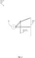
- FIGS. 2-4 are cross-sectional views of deformable stepped lens 102 of FIG. 1 while providing different optical powers in corresponding states regarding the shape of deformable stepped lens 102.
- actuator 104 is not explicitly depicted therein to simplify the views and the associated discussion.
- deformable stepped lens 102 may be in a relaxed state 200 (e.g., a state in which deformable stepped lens 102 is not subjected to a force that would cause a change from its natural shape).
- an eye 201 of a viewer and a display plane 202 may be positioned at opposing sides of deformable stepped lens 102 such that display plane 202 may be in focus at eye 201, as indicated by the selected light rays denoted in FIG. 2 .
- deformable stepped lens 102 may provide some base level of optical power such that an image provided at display plane 202 may appear larger and/or closer to eye 201 that such an image would otherwise appear to eye 201 in the absence of deformable stepped lens 102.
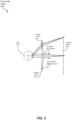
- FIG. 3 depicts deformable stepped lens 102 in a deformed state 300 in which a radial force 301 is applied to a perimeter of deformable stepped lens 102 such that the center of deformable stepped lens 102 exhibits outward movement 110 toward display plane 202. Consequently, as a result of radial force 301, deformable stepped lens 102 may acquire a domed shape (e.g., roughly parabolic in profile) directed toward display plane 202.
- a domed shape e.g., roughly parabolic in profile
- the change in shape of deformable stepped lens 102 from relaxed state 200 (e.g., in which deformable stepped lens 102 may be substantially flat) to deformed state 300 results in a reduction in optical power from the perspective of eye 201 (e.g., from a first optical power in relaxed state 200 to a second (lesser) optical power in deformed state 300). Consequently, presuming no changes in focusing in eye 201, eye 201 may be focused on a plane positioned beyond display plane 202.
- the reduction in optical power may also be attributed, at least in part, to a reduction in distance between the center of deformable stepped lens 102 and display plane 202.
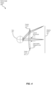
- FIG. 4 depicts deformable stepped lens 102 in another deformed state 400 in which a radial force 401 is applied to a perimeter of deformable stepped lens 102 such that the center of deformable stepped lens 102 exhibits inward movement 112 toward eye 201. Consequently, as a result of radial force 401, deformable stepped lens 102 may acquire a domed shape (e.g., roughly parabolic in profile) directed toward eye 201.
- a domed shape e.g., roughly parabolic in profile
- radial force 301 and radial force 401 may differ in some respect (e.g., by including an additional vector force component aside from a radial component, by applying force to a particular portion of the perimeter of deformable stepped lens 102, etc.) to cause either deformed state 300 or deformed state 400.
- the change in shape of deformable stepped lens 102 from relaxed state 200 (e.g., in which deformable stepped lens 102 may be substantially flat) to deformed state 400 results in an increase in optical power from the perspective of eye 201 (e.g., from a first optical power in relaxed state 200 to a second (greater) optical power in deformed state 300).
- eye 201 may be focused on a plane positioned in front of display plane 202.
- the increase in optical power may also be attributed, at least in part, to an increase in distance between the center of deformable stepped lens 102 and display plane 202.
- eye 201 may alter its optical configuration (e.g., by altering the shape of its lens, by altering the size of its pupil, and so on) so that eye 201 may reacquire focus at display plane 202. Accordingly, the viewer may perceive the change in focus as a change in distance between an image presented at display plane 202 and eye 201.
- the use of radial force 301 and/or radial force 401 may generate a varifocal effect for eye 201 of the viewer.
- the magnitude of radial force 301 or radial force 401 may be related to the amount of change in the optical power provided by deformable stepped lens 102.
- FIGS. 2-4 indicate radial force 301 and/or radial force 401 are applied at a perimeter of deformable stepped lens 102, and are at least primarily directed toward a center of deformable stepped lens 102, alternative examples of a direction of a force and/or a location to which such a force is applied, are possible in other embodiments.
- one or more forces may be applied to locations other than the perimeter of deformable stepped lens 102 in other embodiments, such as at one or both sides of deformable stepped lens 102 inside the perimeter.
- the one or more forces may be applied to such alternative locations, such as away from the center of deformable stepped lens 102, or in other directions apart from toward the center of deformable stepped lens 102.
- relaxed state 200 of FIG. 2 represents an essentially flat state of deformable stepped lens 102
- deformed states 300 and 400 represent domed states of deformable stepped lens -102
- other embodiments may employ different states in the absence or presence of external forces.
- a relaxed state of deformable stepped lens 102 in the absence of an external force may represent a domed shape of deformable stepped lens 102.
- deformable stepped lens 102 may assume a deformed state representing a flat shape in response to one or more radial forces being directed away from the center of deformable stepped lens 102, such as by way of actuator 104 pulling an edge area of deformable stepped lens 102 away from its center.
- actuator 104 pulling an edge area of deformable stepped lens 102 away from its center.
- Other alternative embodiments are also possible.
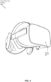
- FIG. 5 is a perspective view of an exemplary HMD 500 that may present images to the eyes (e.g., eye 201) of a viewer as part of a virtual reality (VR), augmented reality (AR), or mixed reality (MR) system.
- HMD 500 may include at least one exemplary display system 501 that may include a varifocal apparatus (e.g., apparatus 100) having a deformable stepped lens (e.g., deformable stepped lens 102).
- a varifocal apparatus e.g., apparatus 100
- a deformable stepped lens e.g., deformable stepped lens 102
- two separate display systems 501, one per user eye may be incorporated in HMD 500.
- FIG. 6 is a side view of an exemplary display system 501 that may be employed within an HMD (e.g., HMD 500 of FIG. 5 ).
- display system 501 may include a display 602 (e.g., a liquid crystal display (LCD), a liquid crystal on silicon (LCoS) display, an organic light-emitting diode (OLED) display, and so on) located on an optical axis 606 with an eye 201 of a viewer.
- a single shared display 602 may be used for both display systems 501.
- deformable stepped lens 102 Also located on optical axis 606, between display 602 and eye 201, may be deformable stepped lens 102, some embodiments of which are described above. Also, as discussed earlier, actuator 104 may be coupled to deformable stepped lens 102 to impart at least one force onto deformable stepped lens 102 to alter the optical power provided by deformable stepped lens 102.
- rigid lens 604 may be located between deformable stepped lens 102 and display 602.
- rigid lens 604 may provide a base amount of optical power, such as to magnify an image provided by display 602 as perceived by eye 201 of the viewer.
- the deformation or doming of deformable stepped lens 102 via actuator 104 may yield differing changes in focal length for different field angles.
- these differences in focal length modification may be mitigated by varying the thickness of deformable stepped lens 102 as a function of the radius of deformable stepped lens 102 so that the amount and profile of curvature of deformable stepped lens 102 under varying levels of force applied by actuator 104 may be controlled.
- rigid lens 604 may be dimensioned to compensate for the variation in thickness of deformable stepped lens 102.
- deformable stepped lens 102 may not be circular (e.g., roughly rectangular) as viewed by eye 201, rigid lens 604 may be dimensioned to compensate for that non-circular shape.
- a controller 612 may be communicatively coupled to deformable stepped lens 102.
- Controller 612 may include hardware logic, a processor (e.g., a microprocessor or microcontroller) that executes one or more software or firmware instructions, or some combination thereof.
- controller 612 may identify an amount of force to be applied via actuator 104 to provide a corresponding level of optical power by deformable stepped lens 102.
- Controller 612 may determine the desired amount of optical power based on input from an application (e.g., a virtual reality application) being executed in a system that includes at least HMD 500. Controller 612 may then direct actuator 104 to provide the identified amount of force to alter the shape of deformable stepped lens 102 to provide the desired optical power.
- an application e.g., a virtual reality application
- display system 501 may include one or more of an input interface 614, a deflectometry subsystem 616, a focus detection subsystem 618, and/or an eye-tracking subsystem 620.
- input interface 614, deflectometry subsystem 616, focus detection subsystem 618, and/or eye-tracking subsystem 620 may be included in, or located external to, HMD 500.
- input interface 614 may receive information (e.g., from the viewer) about an optical correction prescription of the viewer. Based at least in part on this information, controller 612 may identify the amount of force to be applied to deformable stepped lens 102 to control actuator 104.
- the optical correction prescription may include a spherical component that may be provided by deformable stepped lens 102. Further, in some examples, the optical correction prescription may also include a cylindrical component and an axis component associated with astigmatism of eye 201.
- controller 612 may identify a plurality of forces to be applied at different locations of deformable stepped lens 102 so that different amounts of optical power may be applied at different orientations about optical axis 606 according to the spherical, cylindrical, and axis components of the optical correction prescription.
- the viewer may use HMD 500 without corrective eyewear, such as prescription glasses.
- Input interface 614 may provide a user interface (e.g., buttons, switches, keyboard, touchscreen, etc.) that the viewer may employ to enter the optical correction prescription information.
- input interface 614 may be a communication interface (e.g., wired or wireless) coupled to a computer, smartphone, or other device that stores the optical correction prescription information.
- controller 612 may store the optical correction prescription or other information indicative thereof (e.g., control information for actuator 104 for providing the proper optical correction) in association with an identity of the viewer so that the information need not be reentered upon subsequent uses of HMD 500 by the user.
- Deflectometry subsystem 616 may measure a current state of the shape of deformable stepped lens 102. Based on the current state of the shape of deformable stepped lens 102, controller 612 may select one or more forces to apply to deformable stepped lens 102 to alter or adjust the shape of deformable stepped lens 102 via actuator 104 to provide the desired level of optical power. In some examples, deflectometry subsystem 616 may employ any of several techniques involving optical detection, ultrasound detection, or others to detect the current shape of deformable stepped lens 102.
- focus detection subsystem 618 may detect a level of focus of an image provided by display 602. onto or into eye 201 of the viewer. Based at least in part on the detected level of focus, controller 612 may select one or more forces to apply to deformable stepped lens 102 to alter the shape of deformable stepped lens 102 via actuator 104 to provide the desired level of optical power for proper focus to eye 201. In other examples, controller 612 may select one or more forces to apply to deformable stepped lens 102 to alter the shape of deformable stepped lens 102 via actuator 104 to intentionally defocus the image from display 602 to cause an accommodation reflex in eye 201, as discussed above. In some examples, focus detection subsystem 618 may include an optical wavefront sensor or other device for detecting how an image may be perceived in eye 201.
- eye-tracking subsystem 620 e.g., an infrared (IR) based tracking system
- eye-tracking subsystem 620 may provide information indicating a gaze angle of eye 201 (e.g., relative to optical axis 606).
- controller 612 may control the one or more forces imparted on deformable stepped lens 102 via actuator 104 based on that information.
- controller 612 may adjust the optical power provided via deformation of deformable stepped lens 102 based on the current gaze angle of eye 201 in lieu of varying the thickness of deformable stepped lens 102, as described above.
- controller 612 may receive information from deflectometry subsystem 616, focus detection subsystem 618, and/or eye-tracking subsystem 620 on a repetitive or ongoing basis and control actuator 104 accordingly to provide a desired optical power via deformable stepped lens 102 over time.
- controller 612 may implement a closed-loop feedback control system based on the information received from deflectometry subsystem 616, focus detection subsystem 618, and/or eye-tracking subsystem 620.
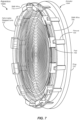
- FIG. 7 is perspective view of an exemplary varifocal apparatus 100A that may include a deformable stepped lens (e.g., deformable stepped lens 102).
- apparatus 100A may also include an actuator 104A having a ring 702, a plurality of pads 706 contacting the perimeter of deformable stepped lens 102, a plurality of flexures 704 extending substantially perpendicularly from ring 702 and connecting pads 706 to ring 702, and a first shape-memory alloy (SMA) wire 708 (e.g., shaped as a ring) routed about pads 706.
- first SMA wire 708 may be routed about flexures 704.
- first SMA wire 708 may be a Nitinol (nickel-titanium alloy) wire, although other alloys or materials may be utilized in other embodiments.
- pads 706 and flexures 704 are positioned equidistant about deformable stepped lens 102. and ring 702, although such an arrangement may not be utilized in other embodiments.
- first SMA wire 708 may retain a length such that essentially no radial force is applied via pads 706 to the perimeter of deformable stepped lens 102, which thus retains a relaxed state (e.g., relaxed state 200) providing a first optical power.
- first SMA wire 708 in response to carrying electrical current, may heat accordingly, causing a reduction in its length, thus forcing pads 706 toward the center of deformable stepped lens 102, thereby deforming the lens into a substantially domed shape and altering the optical power of deformable stepped lens 102, as discussed earlier.
- controller 612 may directly or indirectly provide an amount of current to first SMA wire 708 that is appropriate to cause deformable stepped lens 102 to provide the desired amount of optical power.
- first SMA wire 708 is positioned toward a side of pads 706 closest to flexures 704 such that, when first SMA wire 708 is heated, the center of deformable stepped lens 102 may protrude away from ring 702 so that deformable stepped lens 102 acquires a first deformed state (e.g., deformed state 300).
- a second SMA wire 718 (the position thereof indicated via dashed line in FIG.
- SMA wires 708 and 718 may be located on opposing sides of a plane defined by the perimeter of deformable stepped lens 102 so that deformable stepped lens 102 may be domed in either direction relative to ring 702, thus potentially extending the range of optical powers that may be provided by deformable stepped lens 102.
- multiple SMA wires may be employed instead of a single, thicker SMA wire, such as first SMA wire 708 or second SMA wire 718.
- the multiple SMA wires may provide a similar level of radial force to deformable stepped lens 102 when heated, while possibly cooling more quickly due to exhibiting a greater surface area than a single SMA wire 708 or 718, thus possibly facilitating a more responsive relaxation of deformable stepped lens 102. when the flowing of current through the multiple SMA wires ceases.
- the perimeter of deformable stepped lens 102 may not be circular, in some examples.
- flexures 704 may be of different thicknesses, or the distribution of flexures 704 and pads 706 about the perimeter of deformable stepped lens 102 may not be equidistant, so that a distribution of the force imparted by first SMA wire 708 and/or second SMA wire 718 may actuate deformable stepped lens 102 in a rotationally symmetrical dome shape about the center of deformable stepped lens 102.
- an actuator component other than first SMA wire 708 or second SMA wire 718 may be employed to provide the radial force by way of flexures 704 and pads 706, such as electroactive polymers (EAPs) that may lengthen and contract in response to an electric field.
- EAPs electroactive polymers
- controller 612 may compensate for a hysteretic response of apparatus 100A. More specifically, apparatus 100A may require some period of time during which current flows before first SMA wire 708 or second SMA wire 718 imparts a desired force on the perimeter of deformable stepped lens 102, and may require cooling for some period of time after current ceases to flow prior to first SMA wire 708 or second SMA wire 718 lengthening, thus returning deformable stepped lens 102 to its relaxed state (e.g., relaxed state 200). In such embodiments, controller 612 may implement a predictive control loop to anticipate the need to alter the current through first SMA wire 708 or second SMA wire 718.
- the controller 612 may also employ eye-tracking subsystem 620 to anticipate the need to alter the current to first SMA wire 708 or second SMA wire 718, such as by anticipating a future gaze angle of eye 201 based on a current gaze angle, a direction and/or rate of change of gaze angle, and the like.
- FIG. 8 is a front view of another exemplary varifocal apparatus 100B that may include a deformable stepped lens (e.g., deformable stepped lens 102).
- apparatus 100B may include a plurality of actuators 802 (e.g., collectively operating as actuator 104 of FIG. 1 ), each of which may impart a radial force toward the center of deformable stepped lens 102 to alter the optical power of deformable stepped lens 102.
- actuators 802 may be spaced equidistant about the perimeter of deformable stepped lens 102, although other spacings may be employed in other embodiments.
- actuators 802 may each simultaneously impart the same magnitude of force to each associated location of deformable stepped lens 102, such as to provide an optical power that is substantially the same in all directions about optical axis 606 (e.g., rotationally symmetrical about the center of deformable stepped lens 102).
- different amounts of force may be applied by actuators 802 to provide an optical power that varies about optical axis 606, such as to accommodate astigmatism of eye 201.
- actuators 802 may be positioned and/or oriented relative to the perimeter of deformable stepped lens 102 to force deformable stepped lens 102 to protrude in one direction or another when the force is applied, in a manner analogous to that provided above by apparatus 100A of FIG. 7 .
- Examples of actuators 802 include, but are not limited to, stepper motors, each of which controller 612 may control independently.
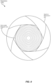
- FIG. 9 is a front view of yet another exemplary varifocal apparatus 100C that may include a deformable stepped lens (e.g., deformable stepped lens 102).
- apparatus 100C may include an aperture mechanism 902 that may be driven by a single actuation motor (e.g., a stepper motor) not explicitly depicted in FIG. 9 .
- Aperture mechanism 902 in response to a force provided by the actuation motor, may apply a force at multiple points on the perimeter of deformable stepped lens 102.
- aperture mechanism 902 may be arranged in a fashion similar to a traditional camera aperture mechanism, with multiple overlapping segments that move simultaneously based on the force from the actuation motor to increase or reduce a radial force at each contact point along the perimeter of deformable stepped lens 102 by a segment of aperture mechanism 902.
- the number of contact points may equal the number of segments. While six contact points are illustrated in FIG. 9 , greater or fewer numbers of contact points and segments may be employed in other examples, with a greater number of points possibly providing a more evenly distributed radial force about the perimeter of deformable stepped lens 102.
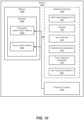
- FIG. 10 is a block diagram of an exemplary system 1000 that may employ a varifocal apparatus (e.g., apparatus 100, 100A, 100B, or 100C) that includes a deformable stepped lens (e.g., deformable stepped lens 102).
- exemplary system 1000 may include one or more modules 1002 for performing one or more tasks.
- modules 1002 may include a prescription determination module 1004 and a force control module 1006.
- a prescription determination module 1004 may include a prescription determination module 1004 and a force control module 1006.
- one or more of modules 1002 in FIG. 10 may represent portions of a single module or application.
- system 1000 may be employed as at least a portion of a display system (e.g., display system 501 of FIGS. 5 and 6 ) for providing varifocal functionality for users of an HMD (e.g., HMD 500 of FIG. 5 ) or other display device.
- a display system e.g., display system 501 of FIGS. 5 and 6
- Such a system may include additional elements 1020, such as deformable stepped lens 102, actuator 104, input interface 614, deflectometry subsystem 616, focus detection subsystem 618, and/or eye-tracking subsystem 620.
- one or more modules 1002 and/or additional elements 1020 e.g., input interface 614, or portions thereof, may reside outside HMD 500 or other display device.
- Prescription determination module 1004 may receive viewer identification information (e.g., from input interface 614) and corresponding optical correction prescription information. Based on such information, prescription determination module 1004 may store information indicative of the prescription (e.g., the optical correction prescription itself, control information for actuator 104, or the like) for each viewer.
- information indicative of the prescription e.g., the optical correction prescription itself, control information for actuator 104, or the like
- focus control module 1006 may receive information to identify or generate a desired optical power that is to be provided by way of imparting a force onto deformable stepped lens 102 via actuator 104.
- Such information may include optical correction prescription information, information from a VR or similar application, a current gaze angle of the user, a proposed accommodation response to be elicited from the eyes of the user, a current force being applied via actuator 104, relationships between force and optical power provided by deformable stepped lens 102, and/or the like. From such information, focus control module 1006 may generate control information for actuator 104 to impart a force on deformable stepped lens 102 to provide a desired optical power for the eyes of the viewer.
- the optical power may facilitate the focusing of the image from a display (e.g., display 602 of FIG. 6 ) onto the eyes, and/or may facilitate slight off-focusing of such an image to elicit the accommodation reflex.
- one or more of modules 1002 in FIG. 10 may represent one or more software applications or programs that, when executed by a computing device, may cause the computing device to perform one or more tasks.
- One or more of modules 1002 in FIG. 10 may also represent all or portions of one or more special-purpose computers configured to perform one or more tasks.
- system 1000 may also include one or more memory devices, such as memory 1040.
- Memory 1040 generally represents any type or form of volatile or non-volatile storage device or medium capable of storing data and/or computer-readable instructions.
- memory 1040 may store, load, and/or maintain one or more of modules 1002.
- system 1000 may also include one or more physical processors, such as physical processor 1030, that may access and/or modify one or more of modules 1002 stored in memory 1040, thus operating as controller 612 of FIG. 6 . Additionally or alternatively, physical processor 1030 may execute one or more of modules 1002.
- modules 1002 instead may be implemented as hardware components not stored in memory 1040, such as electronic circuitry for performing one or more tasks described above.
- memory 1040 may include information generated and/or employed by modules 1002 (e.g., viewer identifiers, information describing optical correction prescriptions of the viewers, control information for actuator 104, and so on), as described above.
- FIG. 11 is a flow diagram of an exemplary method 1100 of varifocal operation that may employ a deformable stepped lens (e.g., deformable stepped lens 102).
- the steps shown in FIG. 11 may be performed by any suitable computer-executable code and/or computing system, including the system(s) illustrated in FIGS. 6 and 10 .
- each of the steps shown in FIG. 11 may represent an algorithm whose structure includes and/or is represented by multiple sub-steps, examples of which are described above in greater detail.
- an amount of force to be applied to the deformable stepped lens may be identified (e.g., by focus control module 1006).
- the amount of force may be based on a particular optical power to be provided by the deformable stepped lens in view of one or more sources of information, including, but not limited to, optical correction prescription information (e.g., received via prescription determination module 1004) for the eyes of the viewer, VR application information, current gaze angle information, information relating force magnitudes to resulting optical powers provided by the deformable stepped lens, and/or the like.
- an actuator e.g., actuator 104 may be directed to apply the identified amount of force to the deformable stepped lens from a first state to the second state, where the deformable stepped lens may include or provide a first optical power in the first state and a second optical power in the second state that is different than the first optical power.
- FIG. 12 is a flow diagram of an exemplary method 1200 of providing a varifocal system (e.g., display system 501 of FIG. 6 ) that may include a deformable stepped lens (e.g., deformable stepped lens 102).
- a deformable stepped lens e.g., deformable stepped lens 102
- an actuation subsystem e.g., actuator 104
- the first state may be a relaxed state, in which a force is not being imparted onto the deformable stepped lens, or may be deformed state, in which at least some force is being imparted onto the deformable stepped lens.
- a control subsystem (e.g., including controller 612) may be communicatively coupled to the actuation subsystem to direct the actuation subsystem to apply a force to the deformable stepped lens, where the force alters the shape of the lens from the first state to a second state, and where the lens, when held in the second state, provides a second optical power that is different from the first optical power.
- the apparatuses, systems, and methods described herein may facilitate a varifocal optical system, such as what may be employed in an HMD or other display system.
- the use of a deformable stepped lens and corresponding actuator, as described above may provide a low-power, volume-efficient means of providing accurate focus for the eyes of a viewer, such as for focusing on an image of a display.
- the apparatuses, systems, and methods herein may also take into account an optical correction prescription of the viewer, thus possibly relieving the viewer of the burden of wearing corrective eyewear, such as prescription glasses, when viewing the display.
- computing devices and systems described and/or illustrated herein broadly represent any type or form of computing device or system capable of executing computer-readable instructions, such as those contained within the modules described herein.
- these computing device(s) may each include at least one memory device and at least one physical processor.
- the term "memory device” generally refers to any type or form of volatile or non-volatile storage device or medium capable of storing data and/or computer-readable instructions.
- a memory device may store, load, and/or maintain one or more of the modules described herein.
- Examples of memory devices include, without limitation, Random Access Memory (RAM), Read Only Memory (ROM), flash memory, Hard Disk Drives (HDDs), Solid-State Drives (SSDs), optical disk drives, caches, variations or combinations of one or more of the same, or any other suitable storage memory.
- the term "physical processor” generally refers to any type or form of hardware-implemented processing unit capable of interpreting and/or executing computer-readable instructions.
- a physical processor may access and/or modify one or more modules stored in the above-described memory device.
- Examples of physical processors include, without limitation, microprocessors, microcontrollers, Central Processing Units (CPUs), Field-Programmable Gate Arrays (FPGAs) that implement softcore processors, Application-Specific Integrated Circuits (ASICs), portions of one or more of the same, variations or combinations of one or more of the same, or any other suitable physical processor.
- modules described and/or illustrated herein may represent portions of a single module or application.
- one or more of these modules may represent one or more software applications or programs that, when executed by a computing device, may cause the computing device to perform one or more tasks.
- one or more of the modules described and/or illustrated herein may represent modules stored and configured to run on one or more of the computing devices or systems described and/or illustrated herein.
- One or more of these modules may also represent all or portions of one or more special-purpose computers configured to perform one or more tasks.
- one or more of the modules described herein may transform data, physical devices, and/or representations of physical devices from one form to another.
- one or more of the modules recited herein may receive data (e.g., application data, optical correction data, etc.) to be transformed, and transform the received data into control signals for an actuator to provide a desired optical power via a deformable stepped lens.
- one or more of the modules recited herein may transform a processor, volatile memory, nonvolatile memory, and/or any other portion of a physical computing device from one form to another by executing on the computing device, storing data on the computing device, and/or otherwise interacting with the computing device.
- the term "computer-readable medium” generally refers to any form of device, carrier, or medium capable of storing or carrying computer-readable instructions.
- Examples of computer-readable media include, without limitation, transmission-type media, such as carrier waves, and non-transitory-type media, such as magnetic-storage media (e.g., hard disk drives, tape drives, and floppy disks), optical-storage media (e.g., Compact Disks (CDs), Digital Video Disks (DVDs), and BLU-RAY disks), electronic-storage media (e.g., solid-state drives and flash media), and other distribution systems.
- transmission-type media such as carrier waves
- non-transitory-type media such as magnetic-storage media (e.g., hard disk drives, tape drives, and floppy disks), optical-storage media (e.g., Compact Disks (CDs), Digital Video Disks (DVDs), and BLU-RAY disks), electronic-storage media (e.g., solid-state drives
- Embodiments of the instant disclosure may include or be implemented in conjunction with an artificial reality system.
- Artificial reality is a form of reality that has been adjusted in some manner before presentation to a user, which may include, e.g., a virtual reality (VR), an augmented reality (AR), a mixed reality (MR), a hybrid reality, or some combination and/or derivatives thereof.
- Artificial reality content may include completely generated content or generated content combined with captured (e.g., real-world) content.
- the artificial reality content may include video, audio, haptic feedback, or some combination thereof, any of which may be presented in a single channel or in multiple channels (such as stereo video that produces a three-dimensional effect to the viewer).
- artificial reality may also be associated with applications, products, accessories, services, or some combination thereof, that are used to, e.g., create content in an artificial reality and/or are otherwise used in (e.g., perform activities in) an artificial reality.
- the artificial reality system that provides the artificial reality content may be implemented on various platforms, including a head-mounted display (HMD) connected to a host computer system, a standalone HMD, a mobile device or computing system, or any other hardware platform capable of providing artificial reality content to one or more viewers.
- HMD head-mounted display
Landscapes
- Physics & Mathematics (AREA)
- General Physics & Mathematics (AREA)
- Optics & Photonics (AREA)
- Engineering & Computer Science (AREA)
- Chemical & Material Sciences (AREA)
- Combustion & Propulsion (AREA)
- Health & Medical Sciences (AREA)
- Ophthalmology & Optometry (AREA)
- Mechanical Engineering (AREA)
- General Engineering & Computer Science (AREA)
- General Health & Medical Sciences (AREA)
- Analytical Chemistry (AREA)
- Prostheses (AREA)
- Eyeglasses (AREA)
- Mechanical Light Control Or Optical Switches (AREA)
Claims (15)
- Eine Head-Mounted-Display-Vorrichtung, die Folgendes beinhaltet:eine verformbare Stufenlinse (102), die:eine erste optische Wirkung bereitstellt, wenn eine Form der verformbaren Stufenlinse einen ersten Zustand beinhaltet; undeine zweite optische Wirkung bereitstellt, die sich von der ersten optischen Wirkung unterscheidet, wenn die Form der verformbaren Stufenlinse einen zweiten Zustand beinhaltet, der sich von dem ersten Zustand unterscheidet; undgekennzeichnet durcheinen mit der verformbaren Stufenlinse gekoppelten Aktuator (104), der konfiguriert ist, um einen Kraftbetrag, der mit der zweiten optischen Wirkung identifiziert wird, auf die verformbare Stufenlinse aufzubringen, um die Form der verformbaren Stufenlinse von dem ersten Zustand in den zweiten Zustand zu ändern.
- Vorrichtung gemäß Anspruch 1, wobei der Aktuator die Kraft um einen Umfang der verformbaren Stufenlinse hin zu einer Mitte der verformbaren Stufenlinse aufbringt.
- Vorrichtung gemäß Anspruch 2, wobei die Kraft, die durch den Aktuator aufgebracht wird, die Mitte der verformbaren Stufenlinse entweder:hin zu einem Auge eines Betrachters bewegt, sodass die zweite optische Wirkung größer als die erste optische Wirkung ist; oderweg von dem Auge des Betrachters bewegt, sodass die zweite optische Wirkung kleiner als die erste optische Wirkung ist.
- Vorrichtung gemäß Anspruch 2, wobei:der Aktuator Folgendes beinhaltet:einen Ring;eine Vielzahl von Auflageflächen, die mit dem Umfang der verformbaren Stufenlinse in Kontakt stehen;eine Vielzahl von Biegeelementen, die die Vielzahl von Auflageflächen mit dem Ring verbinden; undeinen ersten Formgedächtnislegierungsdraht, SMA(Shape-Memory Alloy)-Draht, der über mindestens eines von Folgendem um den Aktuator geführt wird:eine oder mehrere der Vielzahl von Auflageflächen; odereines oder mehrere der Vielzahl von Biegeelementen; undder erste SMA-Draht die Kraft als Reaktion auf das Führen von elektrischem Strom aufbringt.
- Vorrichtung gemäß Anspruch 4, wobei:der Aktuator ferner einen zweiten SMA-Draht beinhaltet, der an der Vielzahl von Auflageflächen um den Aktuator geführt wird;der zweite SMA-Draht eine zweite Kraft um den Umfang der verformbaren Stufenlinse hin zu der Mitte der verformbaren Stufenlinse als Reaktion auf das Führen von elektrischem Strom aufbringt; undder zweite SMA-Draht relativ zu dem ersten SMA-Draht so angeordnet ist, dass die zweite Kraft die Mitte der verformbaren Stufenlinse dazu veranlasst, sich in eine entgegengesetzte Richtung zu derjenigen zu bewegen, die durch die durch den ersten SMA-Draht aufgebrachte Kraft bewirkt wird.
- Vorrichtung gemäß Anspruch 5, wobei der erste SMA-Draht und der zweite SMA-Draht auf gegenüberliegenden Seiten einer Ebene angeordnet sind, die durch den Umfang der verformbaren Stufenlinse definiert ist.
- Vorrichtung gemäß Anspruch 4 und einem von Folgendem:a) wobei:der Umfang der verformbaren Stufenlinse kreisförmig ist; unddie Vielzahl von Biegeelementen eine gleiche Dicke aufweisen, sodass:die gleiche Kraft an jeder der Vielzahl von Auflageflächen auf den Umfang der verformbaren Stufenlinse aufgebracht wird; unddie Form der verformbaren Stufenlinse symmetrisch um die Mitte der verformbaren Stufenlinse ist, wenn sich die verformbare Stufenlinse als ein Ergebnis der Kraft, die an jeder der Vielzahl von Auflageflächen aufgebracht wird, in einem verformten Zustand befindet; oderb) wobei:der Umfang der verformbaren Stufenlinse nicht kreisförmig ist; unddie Vielzahl von Biegeelementen in der Dicke variieren, um unterschiedliche Kräfte an der Vielzahl von Auflageflächen auf den Umfang der verformbaren Stufenlinse aufzubringen, sodass die Form der verformbaren Stufenlinse symmetrisch um die Mitte der verformbaren Stufenlinse ist, wenn sich die verformbare Stufenlinse als ein Ergebnis der Kraft, die an jeder der Vielzahl von Auflageflächen aufgebracht wird, in einem verformten Zustand befindet.
- Vorrichtung gemäß Anspruch 1, wobei:
der Aktuator die Kraft in einer Weise aufbringt, die in Folgendes resultiert:einem ersten Kraftvektor, der an einem ersten Abschnitt der verformbaren Stufenlinse aufgebracht wird; undeinem zweiten Kraftvektor, der an einem zweiten Abschnitt der verformbaren Stufenlinse aufgebracht wird. - Vorrichtung gemäß Anspruch 8 und eines von Folgendem:a) wobei der erste Kraftvektor eine Richtungskomponente beinhaltet, die sich von einer Richtungskomponente des zweiten Kraftvektors unterscheidet; oderb) wobei der Aktuator eine Vielzahl von Aktuatoren beinhaltet, die Folgendes aufweist:einen ersten Aktuator, der den ersten Kraftvektor auf den ersten Abschnitt der verformbaren Stufenlinse aufbringt; undeinen zweiten Aktuator, der den zweiten Kraftvektor auf den zweiten Abschnitt der verformbaren Stufenlinse aufbringt; oderc) ferner beinhaltend einen Blendenmechanismus, der:mit der verformbaren Stufenlinse an einer Vielzahl von unterschiedlichen Stellen gekoppelt ist, wobei die Vielzahl von unterschiedlichen Stellen den ersten und den zweiten Abschnitt der verformbaren Stufenlinse beinhaltet; undbei Betätigung durch den Aktuator die Kraft auf die verformbare Stufenlinse an jeder der Vielzahl von unterschiedlichen Stellen aufbringt.
- Vorrichtung gemäß Anspruch 1 und eines von Folgendem:a) ferner beinhaltend eine starre Linse, die sich zwischen der verformbaren Stufenlinse und einem Auge eines Betrachters befindet und die eine zusätzliche optische Wirkung bereitstellt, wobei die starre Linse bemessen ist, um eine Dicke der verformbaren Stufenlinse zu kompensieren, die sich als eine Funktion eines Radius der verformbaren Stufenlinse unterscheidet; oderb) wobei:die verformbare Stufenlinse mindestens eine im Wesentlichen flache Seite beinhaltet; undeine Seite der verformbaren Stufenlinse gegenüber der im Wesentlichen flachen Seite eine Vielzahl von konzentrischen Rippen beinhaltet; oderc) ferner beinhaltend:ein Display-Teilsystem, das ein Bild zum Betrachten durch einen Betrachter erzeugt, wobei der Aktuator die verformbare Stufenlinse zwischen einem Display und einem Auge des Betrachters hält;ein Steuerungs-Teilsystem, das den Aktuator anweist, die Kraft auf die verformbare Stufenlinse aufzubringen; undein Deflektometrie-Teilsystem, das einen aktuellen Zustand der Form der verformbaren Stufenlinse misst, wobei das Steuerungs-Teilsystem die Kraft, die auf die verformbare Stufenlinse aufgebracht wird, mindestens teilweise basierend auf dem aktuellen Zustand der Form der verformbaren Stufenlinse auswählt.
- Ein Verfahren, das Folgendes beinhaltet:Identifizieren (1110) eines Kraftbetrags, der auf eine verformbare Stufenlinse (102) einer Head-Mounted-Display-Vorrichtung aufzubringen ist; undAnweisen (1120) eines Aktuators (104), den identifizierten Kraftbetrag auf die verformbare Stufenlinse aufzubringen, um eine Form der verformbaren Stufenlinse von einem ersten Zustand in einen zweiten Zustand zu ändern, wobei:die verformbare Stufenlinse eine erste optische Wirkung in dem ersten Zustand beinhaltet;die verformbare Stufenlinse eine zweite optische Wirkung in dem zweiten Zustand beinhaltet; unddie erste optische Wirkung sich von der zweiten optischen Wirkung unterscheidet.
- Verfahren gemäß Anspruch 11, wobei das Identifizieren des Kraftbetrags Folgendes beinhaltet:Detektieren eines Fokusniveaus eines Bildes, das durch die verformbare Stufenlinse auf ein Auge eines Betrachters projiziert wird; undBestimmen, basierend auf dem Fokusniveau, des Kraftbetrags, der auf die verformbare Stufenlinse aufzubringen ist.
- Verfahren gemäß Anspruch 11, wobei das Identifizieren des Kraftbetrags Folgendes beinhaltet:Empfangen, an einem Eingabe-Teilsystem, von Informationen über eine Verordnung einer optischen Korrektur eines Betrachters; undBestimmen, mindestens teilweise basierend auf der Verordnung einer optischen Korrektur, des Kraftbetrags, der auf die verformbare Stufenlinse aufzubringen ist.
- Verfahren gemäß Anspruch 13, wobei:das Empfangen der Informationen über die Verordnung einer optischen Korrektur das Empfangen von Informationen über eine Zylinderkomponente der Verordnung einer optischen Korrektur beinhaltet;das Bestimmen des aufzubringenden Kraftbetrags auf der Zylinderkomponente basiert; die erste optische Wirkung eine erste Zylinderwirkung beinhaltet; unddie zweite optische Wirkung eine zweite Zylinderwirkung beinhaltet, die sich von der ersten zylindrischen Wirkung unterscheidet und die einen Astigmatismus des Betrachters zumindest teilweise korrigiert.
- Ein Verfahren zum Herstellen einer Head-Mounted-Display-Vorrichtung, das Folgendes beinhaltet:mechanisches Koppeln (1210) eines Betätigungs-Teilsystems mit einer verformbaren Stufenlinse (102), die, wenn sie durch das Betätigungs-Teilsystem in einem ersten Zustand gehalten wird, eine Form aufweist, die eine erste optische Wirkung bereitstellt; undkommunikatives Koppeln (1220), mit dem Betätigungs-Teilsystem, eines Steuerungs-Teilsystems, das:einen Kraftbetrag identifiziert, der auf die verformbare Stufenlinse aufzubringen ist;
unddas Betätigungs-Teilsystem anweist, den Kraftbetrag auf die verformbare Stufenlinse aufzubringen, wobei:der Kraftbetrag die Form der verformbaren Stufenlinse von dem ersten Zustand in einen zweiten Zustand ändert; unddie verformbare Stufenlinse, wenn sie durch das Betätigungs-Teilsystem in dem zweiten Zustand gehalten wird, eine zweite optische Wirkung bereitstellt, die sich von der ersten optischen Wirkung unterscheidet.
Applications Claiming Priority (3)
| Application Number | Priority Date | Filing Date | Title |
|---|---|---|---|
| US201862614886P | 2018-01-08 | 2018-01-08 | |
| US15/925,720 US10809524B2 (en) | 2018-01-08 | 2018-03-19 | Varifocal apparatuses, systems, and methods employing a deformable stepped lens |
| PCT/US2018/066935 WO2019135936A1 (en) | 2018-01-08 | 2018-12-20 | Varifocal apparatuses, systems, and methods employing a deformable stepped lens |
Publications (3)
| Publication Number | Publication Date |
|---|---|
| EP3737985A1 EP3737985A1 (de) | 2020-11-18 |
| EP3737985A4 EP3737985A4 (de) | 2021-03-03 |
| EP3737985B1 true EP3737985B1 (de) | 2024-12-04 |
Family
ID=67140722
Family Applications (1)
| Application Number | Title | Priority Date | Filing Date |
|---|---|---|---|
| EP18898491.8A Active EP3737985B1 (de) | 2018-01-08 | 2018-12-20 | Gleitsichtvorrichtungen, systeme und verfahren unter verwendung einer verformbaren gestuften linse |
Country Status (4)
| Country | Link |
|---|---|
| US (1) | US10809524B2 (de) |
| EP (1) | EP3737985B1 (de) |
| CN (1) | CN111602078B (de) |
| WO (1) | WO2019135936A1 (de) |
Families Citing this family (9)
| Publication number | Priority date | Publication date | Assignee | Title |
|---|---|---|---|---|
| US10809524B2 (en) | 2018-01-08 | 2020-10-20 | Facebook Technologies, Llc | Varifocal apparatuses, systems, and methods employing a deformable stepped lens |
| US10852553B2 (en) * | 2018-09-21 | 2020-12-01 | Apple Inc. | Electronic device with a tunable lens |
| WO2021010772A1 (ko) | 2019-07-18 | 2021-01-21 | 삼성전자(주) | 다중 깊이 표현이 가능한 영상 표시 장치 |
| CN112241068B (zh) * | 2019-07-18 | 2024-12-03 | 三星电子株式会社 | 能够多深度表达的图像显示装置 |
| US11774705B1 (en) | 2019-09-25 | 2023-10-03 | Meta Platforms Technologies, Llc | Systems and methods for varifocal adjustment brakes |
| CN111580278B (zh) * | 2020-06-11 | 2022-06-17 | 京东方科技集团股份有限公司 | 一种ar或vr眼镜 |
| CN114280778A (zh) * | 2021-11-24 | 2022-04-05 | 歌尔光学科技有限公司 | 一种智能眼镜及其像距调节方法 |
| CN118871839A (zh) * | 2022-03-17 | 2024-10-29 | 斯纳普公司 | 用于柔性透镜的处方系统 |
| US12158590B2 (en) * | 2022-12-09 | 2024-12-03 | Apple Inc. | Lens mounting systems with flexures coupled to the lens |
Family Cites Families (36)
| Publication number | Priority date | Publication date | Assignee | Title |
|---|---|---|---|---|
| US5774274A (en) | 1995-05-12 | 1998-06-30 | Schachar; Ronald A. | Variable focus lens by small changes of the equatorial lens diameter |
| EP1798592A3 (de) | 1996-01-17 | 2007-09-19 | Nippon Telegraph And Telephone Corporation | Optisches Gerät und dreidimensionale Anzeigevorrichtung |
| JP3783410B2 (ja) | 1998-05-28 | 2006-06-07 | コニカミノルタフォトイメージング株式会社 | 補正光学装置 |
| US10045844B2 (en) * | 2002-02-02 | 2018-08-14 | Powervision, Inc. | Post-implant accommodating lens modification |
| US8778022B2 (en) | 2004-11-02 | 2014-07-15 | E-Vision Smart Optics Inc. | Electro-active intraocular lenses |
| JP4576214B2 (ja) * | 2004-11-26 | 2010-11-04 | オリンパスイメージング株式会社 | 超音波モータおよびレンズ鏡筒 |
| CN100468120C (zh) | 2005-04-15 | 2009-03-11 | 鸿富锦精密工业(深圳)有限公司 | 变焦透镜 |
| CN1928612B (zh) | 2005-09-09 | 2010-05-05 | 鸿富锦精密工业(深圳)有限公司 | 数码相机变焦结构 |
| CN101034201A (zh) | 2006-03-10 | 2007-09-12 | 鸿富锦精密工业(深圳)有限公司 | 一种可变焦透镜模组及采用该透镜模组的镜头模组 |
| US7813047B2 (en) * | 2006-12-15 | 2010-10-12 | Hand Held Products, Inc. | Apparatus and method comprising deformable lens element |
| US20080161914A1 (en) * | 2006-12-29 | 2008-07-03 | Advanced Medical Optics, Inc. | Pre-stressed haptic for accommodating intraocular lens |
| GB2457860B (en) | 2007-02-12 | 2010-06-30 | Cambridge Mechatronics Ltd | Shape memory alloy actuation apparatus |
| JP5194622B2 (ja) | 2007-08-02 | 2013-05-08 | コニカミノルタアドバンストレイヤー株式会社 | 駆動機構、駆動装置およびレンズ駆動装置 |
| CN101419379A (zh) | 2007-10-23 | 2009-04-29 | 鸿富锦精密工业(深圳)有限公司 | 具有自动对焦功能的相机模组及其对焦方法 |
| KR20110015569A (ko) * | 2008-04-23 | 2011-02-16 | 다르마틸레케 사만 | 가변 광학 시스템 및 구성부품 |
| US8395855B2 (en) | 2008-11-20 | 2013-03-12 | Cambridge Mechatronics Limited | Shape memory alloy actuation apparatus |
| US8692929B2 (en) | 2009-01-22 | 2014-04-08 | Panasonic Corporation | Lens drive device, image-capturing device, and electronic apparatus with shape memory alloy actuator |
| US8659835B2 (en) * | 2009-03-13 | 2014-02-25 | Optotune Ag | Lens systems and method |
| KR101044140B1 (ko) | 2009-09-11 | 2011-06-24 | 삼성전기주식회사 | 렌즈 구동 모듈 |
| KR101044219B1 (ko) | 2009-10-19 | 2011-06-29 | 삼성전기주식회사 | 렌즈 구동 모듈 |
| KR101603237B1 (ko) * | 2009-10-27 | 2016-03-15 | 엘지디스플레이 주식회사 | 액정 전계 렌즈 및 이를 이용한 입체 영상 표시 장치 |
| US9329309B2 (en) * | 2012-02-27 | 2016-05-03 | E-Vision Smart Optics, Inc. | Electroactive lens with multiple depth diffractive structures |
| US8919953B1 (en) | 2012-08-02 | 2014-12-30 | Google Inc. | Actuatable contact lenses |
| US20140330375A1 (en) * | 2013-03-11 | 2014-11-06 | Sean J. McCafferty | Accommodating intraocular lens system with mutually-deforming opposing surfaces |
| TWI483005B (zh) * | 2013-07-26 | 2015-05-01 | Nat Univ Tsing Hua | 可調變聚焦元件及其系統 |
| US10108258B2 (en) * | 2013-09-06 | 2018-10-23 | Intel Corporation | Multiple viewpoint image capture of a display user |
| KR102074688B1 (ko) * | 2013-10-29 | 2020-02-10 | 한국전자통신연구원 | 가변 프레넬 렌즈 |
| WO2015134058A1 (en) * | 2014-03-07 | 2015-09-11 | Mccafferty Sean | Refocusable lens system with mutually-applanating internal surfaces |
| GB201412848D0 (en) | 2014-07-18 | 2014-09-03 | Cambridge Mechatronics Ltd | Suspension system for a camera lens element |
| US20160051361A1 (en) * | 2014-08-21 | 2016-02-25 | Emmetrope Incorporated | Accommodating Intraocular Lens |
| JP2017535808A (ja) | 2014-11-12 | 2017-11-30 | アクチュエーター・ソリュ—ションズ・ゲーエムベーハー | カメラモジュールオートフォーカス作動装置およびその制御方法 |
| US10025060B2 (en) | 2015-12-08 | 2018-07-17 | Oculus Vr, Llc | Focus adjusting virtual reality headset |
| KR20170126760A (ko) | 2016-05-10 | 2017-11-20 | 엘지전자 주식회사 | 카메라 모듈 및 그의 오토 포커스 방법 |
| US10095307B2 (en) * | 2016-05-13 | 2018-10-09 | Google Llc | Eye tracking systems and methods for virtual reality environments |
| US10670878B2 (en) | 2016-05-19 | 2020-06-02 | Hutchinson Technology Incorporated | Camera lens suspensions |
| US10809524B2 (en) | 2018-01-08 | 2020-10-20 | Facebook Technologies, Llc | Varifocal apparatuses, systems, and methods employing a deformable stepped lens |
-
2018
- 2018-03-19 US US15/925,720 patent/US10809524B2/en active Active
- 2018-12-20 CN CN201880085441.2A patent/CN111602078B/zh not_active Expired - Fee Related
- 2018-12-20 EP EP18898491.8A patent/EP3737985B1/de active Active
- 2018-12-20 WO PCT/US2018/066935 patent/WO2019135936A1/en not_active Ceased
Also Published As
| Publication number | Publication date |
|---|---|
| CN111602078B (zh) | 2022-05-27 |
| US10809524B2 (en) | 2020-10-20 |
| WO2019135936A1 (en) | 2019-07-11 |
| EP3737985A4 (de) | 2021-03-03 |
| EP3737985A1 (de) | 2020-11-18 |
| CN111602078A (zh) | 2020-08-28 |
| US20190212546A1 (en) | 2019-07-11 |
Similar Documents
| Publication | Publication Date | Title |
|---|---|---|
| EP3737985B1 (de) | Gleitsichtvorrichtungen, systeme und verfahren unter verwendung einer verformbaren gestuften linse | |
| US12498575B2 (en) | Systems and methods for operating a display system based on user perceptibility | |
| CN111771152B (zh) | 用于头戴式显示器中的散光校正的系统和方法 | |
| CN114868069B (zh) | 用电子显示器的中央凹渲染的预测性眼睛跟踪系统和方法 | |
| US11435576B2 (en) | Near-eye display with extended accommodation range adjustment | |
| CN112639943B (zh) | 用于改善头戴式显示器的颜色均匀性的凹式颜色校正 | |
| TW202215107A (zh) | 在近眼顯示器中驅動光源的方法 | |
| US9983412B1 (en) | Wide field of view augmented reality see through head mountable display with distance accommodation | |
| TW201643506A (zh) | 頭戴式顯示裝置 | |
| US20230037329A1 (en) | Optical systems and methods for predicting fixation distance | |
| CN113940055A (zh) | 具有视场移动控制的成像设备 | |
| WO2009131626A2 (en) | Proximal image projection systems | |
| CN117795395A (zh) | 用于预测注视距离的光学系统和方法 | |
| CN114144717A (zh) | 用于减少光学伪影的变迹光学元件 | |
| US12299194B2 (en) | Systems and methods for gaze-assisted gesture control | |
| EP4381337A1 (de) | Optische systeme und verfahren zur vorhersage des fixierabstandes | |
| US11867927B1 (en) | Modified membranes for fluid lenses | |
| US11703618B1 (en) | Display device including lens array with independently operable array sections | |
| US20230341812A1 (en) | Multi-layered polarization volume hologram | |
| US20240297972A1 (en) | System and component architectures for ar and vr devices | |
| US20250306934A1 (en) | Accelerator context switching | |
| CN116184602A (zh) | 瞳孔转向:挠曲件导引系统 | |
| EP3566093A1 (de) | Augennahe anzeige mit erweiterter akkommodationsbereichseinstellung | |
| EP4655665A1 (de) | Systeme und verfahren zur blickunterstützten gestensteuerung | |
| CN117897674A (zh) | 使用自然凝视动力学来检测输入识别错误的系统和方法 |
Legal Events
| Date | Code | Title | Description |
|---|---|---|---|
| STAA | Information on the status of an ep patent application or granted ep patent |
Free format text: STATUS: THE INTERNATIONAL PUBLICATION HAS BEEN MADE |
|
| PUAI | Public reference made under article 153(3) epc to a published international application that has entered the european phase |
Free format text: ORIGINAL CODE: 0009012 |
|
| STAA | Information on the status of an ep patent application or granted ep patent |
Free format text: STATUS: REQUEST FOR EXAMINATION WAS MADE |
|
| 17P | Request for examination filed |
Effective date: 20200805 |
|
| AK | Designated contracting states |
Kind code of ref document: A1 Designated state(s): AL AT BE BG CH CY CZ DE DK EE ES FI FR GB GR HR HU IE IS IT LI LT LU LV MC MK MT NL NO PL PT RO RS SE SI SK SM TR |
|
| AX | Request for extension of the european patent |
Extension state: BA ME |
|
| A4 | Supplementary search report drawn up and despatched |
Effective date: 20210201 |
|
| RIC1 | Information provided on ipc code assigned before grant |
Ipc: G02B 7/09 20210101AFI20210126BHEP |
|
| DAV | Request for validation of the european patent (deleted) | ||
| DAX | Request for extension of the european patent (deleted) | ||
| STAA | Information on the status of an ep patent application or granted ep patent |
Free format text: STATUS: EXAMINATION IS IN PROGRESS |
|
| 17Q | First examination report despatched |
Effective date: 20220708 |
|
| RAP3 | Party data changed (applicant data changed or rights of an application transferred) |
Owner name: META PLATFORMS TECHNOLOGIES, LLC |
|
| REG | Reference to a national code |
Ref country code: DE Ref legal event code: R079 Free format text: PREVIOUS MAIN CLASS: G02B0007090000 Ipc: G02B0027010000 Ref country code: DE Ref legal event code: R079 Ref document number: 602018077392 Country of ref document: DE Free format text: PREVIOUS MAIN CLASS: G02B0007090000 Ipc: G02B0027010000 |
|
| GRAP | Despatch of communication of intention to grant a patent |
Free format text: ORIGINAL CODE: EPIDOSNIGR1 |
|
| STAA | Information on the status of an ep patent application or granted ep patent |
Free format text: STATUS: GRANT OF PATENT IS INTENDED |
|
| RIC1 | Information provided on ipc code assigned before grant |
Ipc: G02C 7/08 20060101ALI20240617BHEP Ipc: F03G 7/06 20060101ALI20240617BHEP Ipc: F03G 7/00 20060101ALI20240617BHEP Ipc: G02B 3/08 20060101ALI20240617BHEP Ipc: G02B 3/14 20060101ALI20240617BHEP Ipc: G02B 27/00 20060101ALI20240617BHEP Ipc: G02B 27/01 20060101AFI20240617BHEP |
|
| INTG | Intention to grant announced |
Effective date: 20240710 |
|
| GRAS | Grant fee paid |
Free format text: ORIGINAL CODE: EPIDOSNIGR3 |
|
| GRAA | (expected) grant |
Free format text: ORIGINAL CODE: 0009210 |
|
| STAA | Information on the status of an ep patent application or granted ep patent |
Free format text: STATUS: THE PATENT HAS BEEN GRANTED |
|
| AK | Designated contracting states |
Kind code of ref document: B1 Designated state(s): AL AT BE BG CH CY CZ DE DK EE ES FI FR GB GR HR HU IE IS IT LI LT LU LV MC MK MT NL NO PL PT RO RS SE SI SK SM TR |
|
| P01 | Opt-out of the competence of the unified patent court (upc) registered |
Free format text: CASE NUMBER: APP_59027/2024 Effective date: 20241029 |
|
| REG | Reference to a national code |
Ref country code: GB Ref legal event code: FG4D |
|
| REG | Reference to a national code |
Ref country code: CH Ref legal event code: EP |
|
| REG | Reference to a national code |
Ref country code: DE Ref legal event code: R096 Ref document number: 602018077392 Country of ref document: DE |
|
| REG | Reference to a national code |
Ref country code: IE Ref legal event code: FG4D |
|
| REG | Reference to a national code |
Ref country code: LT Ref legal event code: MG9D |
|
| REG | Reference to a national code |
Ref country code: NL Ref legal event code: MP Effective date: 20241204 |
|
| PG25 | Lapsed in a contracting state [announced via postgrant information from national office to epo] |
Ref country code: HR Free format text: LAPSE BECAUSE OF FAILURE TO SUBMIT A TRANSLATION OF THE DESCRIPTION OR TO PAY THE FEE WITHIN THE PRESCRIBED TIME-LIMIT Effective date: 20241204 |
|
| PGFP | Annual fee paid to national office [announced via postgrant information from national office to epo] |
Ref country code: DE Payment date: 20241231 Year of fee payment: 7 |
|
| PG25 | Lapsed in a contracting state [announced via postgrant information from national office to epo] |
Ref country code: FI Free format text: LAPSE BECAUSE OF FAILURE TO SUBMIT A TRANSLATION OF THE DESCRIPTION OR TO PAY THE FEE WITHIN THE PRESCRIBED TIME-LIMIT Effective date: 20241204 |
|
| PG25 | Lapsed in a contracting state [announced via postgrant information from national office to epo] |
Ref country code: BG Free format text: LAPSE BECAUSE OF FAILURE TO SUBMIT A TRANSLATION OF THE DESCRIPTION OR TO PAY THE FEE WITHIN THE PRESCRIBED TIME-LIMIT Effective date: 20241204 |
|
| PG25 | Lapsed in a contracting state [announced via postgrant information from national office to epo] |
Ref country code: ES Free format text: LAPSE BECAUSE OF FAILURE TO SUBMIT A TRANSLATION OF THE DESCRIPTION OR TO PAY THE FEE WITHIN THE PRESCRIBED TIME-LIMIT Effective date: 20241204 |
|
| PG25 | Lapsed in a contracting state [announced via postgrant information from national office to epo] |
Ref country code: NO Free format text: LAPSE BECAUSE OF FAILURE TO SUBMIT A TRANSLATION OF THE DESCRIPTION OR TO PAY THE FEE WITHIN THE PRESCRIBED TIME-LIMIT Effective date: 20250304 |
|
| PG25 | Lapsed in a contracting state [announced via postgrant information from national office to epo] |
Ref country code: GR Free format text: LAPSE BECAUSE OF FAILURE TO SUBMIT A TRANSLATION OF THE DESCRIPTION OR TO PAY THE FEE WITHIN THE PRESCRIBED TIME-LIMIT Effective date: 20250305 Ref country code: LV Free format text: LAPSE BECAUSE OF FAILURE TO SUBMIT A TRANSLATION OF THE DESCRIPTION OR TO PAY THE FEE WITHIN THE PRESCRIBED TIME-LIMIT Effective date: 20241204 |
|
| PG25 | Lapsed in a contracting state [announced via postgrant information from national office to epo] |
Ref country code: RS Free format text: LAPSE BECAUSE OF FAILURE TO SUBMIT A TRANSLATION OF THE DESCRIPTION OR TO PAY THE FEE WITHIN THE PRESCRIBED TIME-LIMIT Effective date: 20250304 |
|
| PG25 | Lapsed in a contracting state [announced via postgrant information from national office to epo] |
Ref country code: NL Free format text: LAPSE BECAUSE OF FAILURE TO SUBMIT A TRANSLATION OF THE DESCRIPTION OR TO PAY THE FEE WITHIN THE PRESCRIBED TIME-LIMIT Effective date: 20241204 |
|
| REG | Reference to a national code |
Ref country code: AT Ref legal event code: MK05 Ref document number: 1748776 Country of ref document: AT Kind code of ref document: T Effective date: 20241204 |
|
| PG25 | Lapsed in a contracting state [announced via postgrant information from national office to epo] |
Ref country code: SM Free format text: LAPSE BECAUSE OF FAILURE TO SUBMIT A TRANSLATION OF THE DESCRIPTION OR TO PAY THE FEE WITHIN THE PRESCRIBED TIME-LIMIT Effective date: 20241204 |
|
| PG25 | Lapsed in a contracting state [announced via postgrant information from national office to epo] |
Ref country code: PL Free format text: LAPSE BECAUSE OF FAILURE TO SUBMIT A TRANSLATION OF THE DESCRIPTION OR TO PAY THE FEE WITHIN THE PRESCRIBED TIME-LIMIT Effective date: 20241204 |
|
| PG25 | Lapsed in a contracting state [announced via postgrant information from national office to epo] |
Ref country code: IS Free format text: LAPSE BECAUSE OF FAILURE TO SUBMIT A TRANSLATION OF THE DESCRIPTION OR TO PAY THE FEE WITHIN THE PRESCRIBED TIME-LIMIT Effective date: 20250404 |
|
| PG25 | Lapsed in a contracting state [announced via postgrant information from national office to epo] |
Ref country code: PT Free format text: LAPSE BECAUSE OF FAILURE TO SUBMIT A TRANSLATION OF THE DESCRIPTION OR TO PAY THE FEE WITHIN THE PRESCRIBED TIME-LIMIT Effective date: 20250404 |
|
| PG25 | Lapsed in a contracting state [announced via postgrant information from national office to epo] |
Ref country code: EE Free format text: LAPSE BECAUSE OF FAILURE TO SUBMIT A TRANSLATION OF THE DESCRIPTION OR TO PAY THE FEE WITHIN THE PRESCRIBED TIME-LIMIT Effective date: 20241204 |
|
| PG25 | Lapsed in a contracting state [announced via postgrant information from national office to epo] |
Ref country code: AT Free format text: LAPSE BECAUSE OF FAILURE TO SUBMIT A TRANSLATION OF THE DESCRIPTION OR TO PAY THE FEE WITHIN THE PRESCRIBED TIME-LIMIT Effective date: 20241204 Ref country code: RO Free format text: LAPSE BECAUSE OF FAILURE TO SUBMIT A TRANSLATION OF THE DESCRIPTION OR TO PAY THE FEE WITHIN THE PRESCRIBED TIME-LIMIT Effective date: 20241204 |
|
| PG25 | Lapsed in a contracting state [announced via postgrant information from national office to epo] |
Ref country code: SK Free format text: LAPSE BECAUSE OF FAILURE TO SUBMIT A TRANSLATION OF THE DESCRIPTION OR TO PAY THE FEE WITHIN THE PRESCRIBED TIME-LIMIT Effective date: 20241204 |
|
| PG25 | Lapsed in a contracting state [announced via postgrant information from national office to epo] |
Ref country code: CZ Free format text: LAPSE BECAUSE OF FAILURE TO SUBMIT A TRANSLATION OF THE DESCRIPTION OR TO PAY THE FEE WITHIN THE PRESCRIBED TIME-LIMIT Effective date: 20241204 |
|
| PG25 | Lapsed in a contracting state [announced via postgrant information from national office to epo] |
Ref country code: IT Free format text: LAPSE BECAUSE OF FAILURE TO SUBMIT A TRANSLATION OF THE DESCRIPTION OR TO PAY THE FEE WITHIN THE PRESCRIBED TIME-LIMIT Effective date: 20241204 |
|
| REG | Reference to a national code |
Ref country code: CH Ref legal event code: PL |
|
| PG25 | Lapsed in a contracting state [announced via postgrant information from national office to epo] |
Ref country code: LU Free format text: LAPSE BECAUSE OF NON-PAYMENT OF DUE FEES Effective date: 20241220 |
|
| REG | Reference to a national code |
Ref country code: DE Ref legal event code: R097 Ref document number: 602018077392 Country of ref document: DE |
|
| PG25 | Lapsed in a contracting state [announced via postgrant information from national office to epo] |
Ref country code: SE Free format text: LAPSE BECAUSE OF FAILURE TO SUBMIT A TRANSLATION OF THE DESCRIPTION OR TO PAY THE FEE WITHIN THE PRESCRIBED TIME-LIMIT Effective date: 20241204 |
|
| PG25 | Lapsed in a contracting state [announced via postgrant information from national office to epo] |
Ref country code: MC Free format text: LAPSE BECAUSE OF FAILURE TO SUBMIT A TRANSLATION OF THE DESCRIPTION OR TO PAY THE FEE WITHIN THE PRESCRIBED TIME-LIMIT Effective date: 20241204 |
|
| REG | Reference to a national code |
Ref country code: BE Ref legal event code: MM Effective date: 20241231 |
|
| PG25 | Lapsed in a contracting state [announced via postgrant information from national office to epo] |
Ref country code: DK Free format text: LAPSE BECAUSE OF FAILURE TO SUBMIT A TRANSLATION OF THE DESCRIPTION OR TO PAY THE FEE WITHIN THE PRESCRIBED TIME-LIMIT Effective date: 20241204 |
|
| PLBE | No opposition filed within time limit |
Free format text: ORIGINAL CODE: 0009261 |
|
| STAA | Information on the status of an ep patent application or granted ep patent |
Free format text: STATUS: NO OPPOSITION FILED WITHIN TIME LIMIT |
|
| PG25 | Lapsed in a contracting state [announced via postgrant information from national office to epo] |
Ref country code: BE Free format text: LAPSE BECAUSE OF NON-PAYMENT OF DUE FEES Effective date: 20241231 |
|
| PG25 | Lapsed in a contracting state [announced via postgrant information from national office to epo] |
Ref country code: CH Free format text: LAPSE BECAUSE OF NON-PAYMENT OF DUE FEES Effective date: 20241231 |
|
| PG25 | Lapsed in a contracting state [announced via postgrant information from national office to epo] |
Ref country code: IE Free format text: LAPSE BECAUSE OF NON-PAYMENT OF DUE FEES Effective date: 20241220 |
|
| 26N | No opposition filed |
Effective date: 20250905 |
|
| PGFP | Annual fee paid to national office [announced via postgrant information from national office to epo] |
Ref country code: GB Payment date: 20251223 Year of fee payment: 8 |
|
| PG25 | Lapsed in a contracting state [announced via postgrant information from national office to epo] |
Ref country code: FR Free format text: LAPSE BECAUSE OF NON-PAYMENT OF DUE FEES Effective date: 20250204 |