EP3737178B1 - Datensendeverfahren, datenempfangsverfahren, endgerät und netzwerkvorrichtung - Google Patents
Datensendeverfahren, datenempfangsverfahren, endgerät und netzwerkvorrichtung Download PDFInfo
- Publication number
- EP3737178B1 EP3737178B1 EP18900192.8A EP18900192A EP3737178B1 EP 3737178 B1 EP3737178 B1 EP 3737178B1 EP 18900192 A EP18900192 A EP 18900192A EP 3737178 B1 EP3737178 B1 EP 3737178B1
- Authority
- EP
- European Patent Office
- Prior art keywords
- terminal device
- indicates
- target resource
- mod
- configuration information
- Prior art date
- Legal status (The legal status is an assumption and is not a legal conclusion. Google has not performed a legal analysis and makes no representation as to the accuracy of the status listed.)
- Active
Links
- 238000000034 method Methods 0.000 title claims description 53
- 230000005540 biological transmission Effects 0.000 claims description 80
- 238000012545 processing Methods 0.000 claims description 27
- 230000011664 signaling Effects 0.000 claims description 12
- 230000015654 memory Effects 0.000 description 31
- 238000004891 communication Methods 0.000 description 15
- 230000008569 process Effects 0.000 description 9
- 238000010586 diagram Methods 0.000 description 8
- 230000006870 function Effects 0.000 description 4
- 238000013507 mapping Methods 0.000 description 4
- 230000001360 synchronised effect Effects 0.000 description 4
- 230000008878 coupling Effects 0.000 description 3
- 238000010168 coupling process Methods 0.000 description 3
- 238000005859 coupling reaction Methods 0.000 description 3
- 238000013461 design Methods 0.000 description 3
- 238000005516 engineering process Methods 0.000 description 3
- 230000007246 mechanism Effects 0.000 description 3
- 230000001413 cellular effect Effects 0.000 description 2
- 238000004590 computer program Methods 0.000 description 2
- 238000013468 resource allocation Methods 0.000 description 2
- 230000003068 static effect Effects 0.000 description 2
- 230000001934 delay Effects 0.000 description 1
- 230000000977 initiatory effect Effects 0.000 description 1
- 230000003993 interaction Effects 0.000 description 1
- 230000007774 longterm Effects 0.000 description 1
- 238000010295 mobile communication Methods 0.000 description 1
- 230000003287 optical effect Effects 0.000 description 1
Images


Classifications
-
- H—ELECTRICITY
- H04—ELECTRIC COMMUNICATION TECHNIQUE
- H04W—WIRELESS COMMUNICATION NETWORKS
- H04W8/00—Network data management
- H04W8/02—Processing of mobility data, e.g. registration information at HLR [Home Location Register] or VLR [Visitor Location Register]; Transfer of mobility data, e.g. between HLR, VLR or external networks
- H04W8/08—Mobility data transfer
-
- H—ELECTRICITY
- H04—ELECTRIC COMMUNICATION TECHNIQUE
- H04W—WIRELESS COMMUNICATION NETWORKS
- H04W72/00—Local resource management
- H04W72/50—Allocation or scheduling criteria for wireless resources
- H04W72/53—Allocation or scheduling criteria for wireless resources based on regulatory allocation policies
-
- H—ELECTRICITY
- H04—ELECTRIC COMMUNICATION TECHNIQUE
- H04W—WIRELESS COMMUNICATION NETWORKS
- H04W72/00—Local resource management
- H04W72/20—Control channels or signalling for resource management
- H04W72/23—Control channels or signalling for resource management in the downlink direction of a wireless link, i.e. towards a terminal
-
- H—ELECTRICITY
- H04—ELECTRIC COMMUNICATION TECHNIQUE
- H04L—TRANSMISSION OF DIGITAL INFORMATION, e.g. TELEGRAPHIC COMMUNICATION
- H04L5/00—Arrangements affording multiple use of the transmission path
- H04L5/003—Arrangements for allocating sub-channels of the transmission path
- H04L5/0032—Distributed allocation, i.e. involving a plurality of allocating devices, each making partial allocation
-
- H—ELECTRICITY
- H04—ELECTRIC COMMUNICATION TECHNIQUE
- H04B—TRANSMISSION
- H04B1/00—Details of transmission systems, not covered by a single one of groups H04B3/00 - H04B13/00; Details of transmission systems not characterised by the medium used for transmission
- H04B1/69—Spread spectrum techniques
- H04B1/713—Spread spectrum techniques using frequency hopping
-
- H—ELECTRICITY
- H04—ELECTRIC COMMUNICATION TECHNIQUE
- H04L—TRANSMISSION OF DIGITAL INFORMATION, e.g. TELEGRAPHIC COMMUNICATION
- H04L5/00—Arrangements affording multiple use of the transmission path
- H04L5/003—Arrangements for allocating sub-channels of the transmission path
- H04L5/0044—Arrangements for allocating sub-channels of the transmission path allocation of payload
-
- H—ELECTRICITY
- H04—ELECTRIC COMMUNICATION TECHNIQUE
- H04L—TRANSMISSION OF DIGITAL INFORMATION, e.g. TELEGRAPHIC COMMUNICATION
- H04L5/00—Arrangements affording multiple use of the transmission path
- H04L5/0091—Signaling for the administration of the divided path
- H04L5/0094—Indication of how sub-channels of the path are allocated
-
- H—ELECTRICITY
- H04—ELECTRIC COMMUNICATION TECHNIQUE
- H04W—WIRELESS COMMUNICATION NETWORKS
- H04W16/00—Network planning, e.g. coverage or traffic planning tools; Network deployment, e.g. resource partitioning or cells structures
- H04W16/02—Resource partitioning among network components, e.g. reuse partitioning
- H04W16/10—Dynamic resource partitioning
-
- H—ELECTRICITY
- H04—ELECTRIC COMMUNICATION TECHNIQUE
- H04W—WIRELESS COMMUNICATION NETWORKS
- H04W24/00—Supervisory, monitoring or testing arrangements
- H04W24/02—Arrangements for optimising operational condition
-
- H—ELECTRICITY
- H04—ELECTRIC COMMUNICATION TECHNIQUE
- H04W—WIRELESS COMMUNICATION NETWORKS
- H04W28/00—Network traffic management; Network resource management
- H04W28/02—Traffic management, e.g. flow control or congestion control
- H04W28/0231—Traffic management, e.g. flow control or congestion control based on communication conditions
- H04W28/0236—Traffic management, e.g. flow control or congestion control based on communication conditions radio quality, e.g. interference, losses or delay
-
- H—ELECTRICITY
- H04—ELECTRIC COMMUNICATION TECHNIQUE
- H04W—WIRELESS COMMUNICATION NETWORKS
- H04W28/00—Network traffic management; Network resource management
- H04W28/02—Traffic management, e.g. flow control or congestion control
- H04W28/0268—Traffic management, e.g. flow control or congestion control using specific QoS parameters for wireless networks, e.g. QoS class identifier [QCI] or guaranteed bit rate [GBR]
-
- H—ELECTRICITY
- H04—ELECTRIC COMMUNICATION TECHNIQUE
- H04W—WIRELESS COMMUNICATION NETWORKS
- H04W4/00—Services specially adapted for wireless communication networks; Facilities therefor
-
- H—ELECTRICITY
- H04—ELECTRIC COMMUNICATION TECHNIQUE
- H04W—WIRELESS COMMUNICATION NETWORKS
- H04W72/00—Local resource management
- H04W72/02—Selection of wireless resources by user or terminal
-
- H—ELECTRICITY
- H04—ELECTRIC COMMUNICATION TECHNIQUE
- H04W—WIRELESS COMMUNICATION NETWORKS
- H04W72/00—Local resource management
- H04W72/04—Wireless resource allocation
- H04W72/044—Wireless resource allocation based on the type of the allocated resource
- H04W72/0446—Resources in time domain, e.g. slots or frames
-
- H—ELECTRICITY
- H04—ELECTRIC COMMUNICATION TECHNIQUE
- H04W—WIRELESS COMMUNICATION NETWORKS
- H04W72/00—Local resource management
- H04W72/04—Wireless resource allocation
- H04W72/044—Wireless resource allocation based on the type of the allocated resource
- H04W72/0453—Resources in frequency domain, e.g. a carrier in FDMA
-
- H—ELECTRICITY
- H04—ELECTRIC COMMUNICATION TECHNIQUE
- H04W—WIRELESS COMMUNICATION NETWORKS
- H04W80/00—Wireless network protocols or protocol adaptations to wireless operation
- H04W80/08—Upper layer protocols
-
- H—ELECTRICITY
- H04—ELECTRIC COMMUNICATION TECHNIQUE
- H04L—TRANSMISSION OF DIGITAL INFORMATION, e.g. TELEGRAPHIC COMMUNICATION
- H04L5/00—Arrangements affording multiple use of the transmission path
- H04L5/0091—Signaling for the administration of the divided path
Definitions
- Embodiments of the present disclosure relate to the field of communications, and more particularly, to a data transmitting method, a data receiving method, a terminal device, and a network device.
- inter-slot and intra-slot frequency hopping are introduced in fifth-generation mobile communication technology (5-Generation, 5G) New Radio (NR) systems.
- 5G fifth-generation mobile communication technology
- NR New Radio
- intra-slot frequency hopping has been sufficiently discussed, but basically there is no clear conclusion on inter-slot frequency hopping. Therefore, current intra-slot frequency hopping is not able to work.
- Ultra-Reliable and Low Latency Communication is also introduced in 5G.
- This communication service is characterized by achieving ultra-reliable (e.g., 99.999%) transmissions within extreme delays (e.g., 1 ms).
- ultra-reliable e.g., 99.999%
- extreme delays e.g., 1 ms.
- Grant free uses a pre-configured/semi-persistent resource allocation mode, and a terminal can transmit on configured resources according to service needs. This technology avoids a process of schedule request (SR) and buffer status report (BSR), which increases effective transmission time of the terminal.
- SR schedule request
- BSR buffer status report
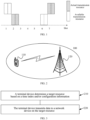
- a location where a user initiates a transmission is flexible, including starting at a determined location and a random location. Due to starting at a random location, an access user is not controllable, so the problem of interference by the access user also needs to be considered in the design of frequency hopping. For example, if a terminal device uses a non-slot transmission, as shown in FIG. 1 , the actual transmission of the terminal may only occur on a same frequency domain resource. Frequency diversity gain cannot be guaranteed to be obtained in the non-slot transmission. As a result, transmission resources of multiple terminals overlap, thereby causing user conflicts.
- EP2946624A1 describes a method which includes implementing, by a base station (BS), a grant-free uplink transmission scheme.
- the grant-free uplink transmission scheme defines a first contention transmission unit (CTU) access region in a time-frequency domain, defines a plurality of CTUs, defines a default CTU mapping scheme by mapping at least some of the plurality of CTUs to the first CTU access region, and defines a default user equipment (UE) mapping scheme by defining rules for mapping a plurality of UEs to the plurality of CTUs.
- CTU contention transmission unit
- UE user equipment
- WO2016167828A1 describes systems, devices, and methods for grantless uplink transmissions in cellular networks, which may include a detailed physical layer design for grantless uplink transmissions, and in particular, may include, for grantless uplink transmissions, enhanced mechanisms; transmission schemes; repeated transmissions; demodulation reference signal (DM-RS); power control mechanisms; and interference control mechanisms.
- DM-RS demodulation reference signal
- a data transmitting method, a data receiving method, a terminal device, and a network device are provided, which can effectively improve the frequency diversity gain in the non-slot transmission.
- a data transmitting method where the method is applied to non-slot transmission and the method includes:
- the terminal device in embodiments of the present application directly determines the target resource according to the time index, the terminal device can control resource granularity of the target resource to meet transmission requirements of the terminal device, and can further avoid an actual data transmission process from occurring only on a same frequency domain resource, thereby further improving the frequency diversity gain in the non-slot transmission.
- the terminal device determines the target resource based on the configuration information, randomness of interference can be enhanced as much as possible to avoid a same user from always or frequently being in conflict, so when a DMRS of the terminal device conflicts with that of other terminals, performance of user identification can be effectively improved, and system transmission efficiency is improved.
- the time unit is determined by the terminal device through high-level signaling or physical layer signaling transmitted by the network device.
- the method before the determining, by a terminal device, a target resource based on an index of a time unit and configuration information, the method further includes: receiving, by the terminal device, the configuration information transmitted by the network device, where the configuration information is specific information for the terminal device.
- a data receiving method where the method is applied to non-slot transmission and the method includes:
- a terminal device configured to non-slot transmission and the terminal device includes: a processing unit, configured to determine a target resource based on an index of a time unit and configuration information; and a transceiving unit, configured to transmit data to a network device on the target resource;
- a terminal device configured to apply to non-slot transmission and the terminal device includes: a processor, configured to determine a target resource based on an index of a time unit and configuration information; and a transceiver, configured to transmit data to a network device on the target resource;
- a network device configured to transmit configuration information to a terminal device; and receive, on a target resource, data transmitted by the terminal device; where the target resource is determined by a processing unit of the network device based on an index of a time unit and the configuration information;
- a network device configured to apply to non-slot transmission and the network device includes: a transceiver, configured to transmit configuration information to a terminal device; and receive, on a target resource, data transmitted by the terminal device; where the target resource is determined by a processor of the network device based on an index of a time unit and the configuration information;
- a computer-readable medium for storing a computer program, where the computer program includes instructions for executing the method of the first aspect or the second aspect described above.
- a computer chip including: an input interface, an output interface, at least one processor and a memory, where the processor is configured to execute a code in the memory, and when the code is executed, the processor can implement the various processes performed by the terminal device in the data transmitting method in the first aspect and the various implementations thereof described above.
- a computer chip including: an input interface, an output interface, at least one processor and a memory, where the processor is configured to execute a code in the memory, and when the code is executed, the processor can implement the various processes performed by the network device in the data receiving method in the second aspect and various implementations thereof described above.
- a communication system including the network device and the terminal device described above.
- FIG. 2 is a schematic diagram of a 5G application scenario according to an embodiment of the present disclosure.
- a communication system 100 may include a terminal device 110 and a network device 120.
- the network device 120 may communicate with the terminal device 110 through an air interface. Multi-service transmission is supported between the terminal device 110 and the network device 120.
- the 5G communication system 100 is taken in embodiments of the present disclosure only for exemplary illustration, but the embodiments of the present disclosure are not limited thereto. That is, the technical solutions of the embodiments of the present disclosure may be applied to various scenarios including a 5G communication system.
- a scenario with mixed deployment composed of a 5G communication system and a first communication system.
- the first communication system may be any type of communication system, for example, a Long Term Evolution (LTE) system, a LTE Time Division Duplex (TDD) system, and a Universal Mobile Telecommunication System (UMTS), etc.
- LTE Long Term Evolution
- TDD Time Division Duplex
- UMTS Universal Mobile Telecommunication System
- the network device 120 may refer to any entity that is configured to transmit or receive a signal on a network side, for example, a base station device in a 5G network.
- the terminal device 110 may be any terminal device. Specifically, the terminal device 110 may communicate with one or more core networks via a radio access network (RAN), and may also be referred to as an access terminal, a user equipment (UE), a subscriber unit, a subscriber station, a mobile station, a mobile platform, a remote station, a remote terminal, a mobile device, a user terminal, a terminal, a wireless communication device, a user agent, or a user apparatus.
- RAN radio access network
- it can be a cellular phone, a cordless phone, a Session Initiation Protocol (SIP) phone, a Wireless Local Loop (WLL) station, a Personal Digital Assistant (PDA), and a handheld device with wireless communication functions, a computing device, or other processing devices connected to a wireless modem, an in-vehicle device, a wearable devices, and etc.
- SIP Session Initiation Protocol
- WLL Wireless Local Loop
- PDA Personal Digital Assistant
- FIG. 3 is a schematic flowchart of a data transmitting method according to an embodiment of the present disclosure.
- the method includes:
- the terminal device may directly determine the target resource based on the time index, or the terminal device may determine the target resource through the configuration information transmitted by the network device. Then, the terminal device transmits data to the network device on the target resource. Furthermore, the configuration information includes information for the terminal device to determine the target resource based on the time index.
- the terminal device determines the target resource based on the configuration information
- the terminal device receives the configuration information transmitted by the network device before it determines the target resource based on the configuration information, where the configuration information is specific information for the terminal device. Therefore, the terminal device determines the target resource according to the configuration information.
- the network device may also determine the target resource based on the configuration information, and receive, on the target resource, the data transmitted by the terminal device.
- the network device determines the configuration information for the terminal device to determine the target resource based on the time index, where the configuration information is specific information for the terminal device. Before the network device determines the target resource based on the configuration information, the network device transmits the configuration information to the terminal device.
- an interaction process between a network device and a terminal device in embodiments of the present application includes:
- the time index may be understood as an index of a time unit, where the time unit may be understood as a period of time.
- a length of the period of time is not specifically limited in the embodiments of the present application.
- a unit of the time unit corresponding to the time index includes at least one of the following: at least one symbol, at least one slot, and at least one transmission opportunity.
- the unit of the time unit corresponding to the time index may be one symbol, or a time period composed of multiple symbols, or one slot, or a time period composed of multiple slots.
- a unit of a time unit corresponding to the time index is determined by the terminal device through high-level signaling or physical layer signaling transmitted by the network device.
- the unit of the time unit corresponding to the time index may be directly indicated by the network device or indirectly indicated by the network device, and the unit of the time unit corresponding to the time index may also be specified through a protocol, which is not specifically limited in the present application.
- time unit involved in the embodiments of the present application may refer to a relative time unit or an absolute time unit, which is not specifically limited in the embodiments of the present application.
- the terminal device in the embodiments of the present application directly determines the target resource according to the time index, the terminal device can control resource granularity of the target resource to meet transmission requirements of the terminal device, and can further avoid an actual data transmission process from occurring only on a same frequency domain resource, thereby further improving the frequency diversity gain in the non-slot transmission.
- DMRS demodulation reference signal
- the terminal device may directly determine the target resource based on the time index, and then control a resource granularity of the target resource.
- the terminal device may also directly control the resource granularity of the target resource and determine the target resource based on the configuration information, and avoid resource conflicts.
- implementations of determining the target resource are not specifically limited in the embodiments of the present application.
- the terminal device may also determine the target resource according to a number of times of data transmission. That is, the terminal device determines a resource location of the target resource based on the number of times of data transmission.
- the configuration information includes at least one of the following information: a first frequency hopping parameter RB start , a second frequency hopping parameter RB offset , an available resource amount N, a frequency hopping parameter K, and a cut-off point parameter B, where RB start indicates a starting resource location and RB offset is used for the terminal device to obtain a resource location in a next hop. Therefore, the terminal device can obtain the target resource based on respective parameter information in the configuration information.
- implementations of determining the target resource based on the configuration information are applicable to both a terminal device side and a network device side. Therefore, in order to avoid repetition, below the terminal device side is taken as an example for exemplary description.
- the following is an exemplary illustration of a specific implementation of the terminal device determining the target resource based on the example parameters of the configuration information described above.
- the configuration information can include the first frequency hopping parameter RB start and/or the second frequency hopping parameter RB offset .
- the unit of the time unit is one transmission opportunity. It should be understood that when the target resource is determined using the above formula (2), the configuration information can include the first frequency hopping parameter RB start and/or the second frequency hopping parameter RB offset .
- the configuration information can include any one of the first frequency hopping parameter RB start , the second frequency hopping parameter RB offset , and the available resource amount N.
- N BWP size 3
- N can be greater than or equal to 2.
- the configuration information can include any one of the first frequency hopping parameter RB start , the second frequency hopping parameter RB offset , and the cut-off point parameter B.
- a probability of resource conflict occurring between the user 1 and the user 2 can be effectively reduced.
- the configuration information can include any one of the first frequency hopping parameter RB start , the second frequency hopping parameter RB offset , and the frequency hopping parameter K.
- K can be implicitly or explicitly configured by the network device.
- K is equal to a number of times of repeated transmissions of the data.
- K can default to be equal to a first value; and if the number of times of repeated transmissions of the data is configured by the terminal device, K is equal to the number of times of repeated transmissions of the data.
- K can default to be equal to 2; and if the number of times of repeated transmissions of the data is configured by the terminal device, K is equal to the number of times of repeated transmissions of the data.
- the configuration information includes location information of the target resource. Therefore, the terminal device can directly transmit the data to the network device based on the location information of the target resource.
- the configuration information in an example of the present application includes a series of transmission resources.
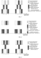
- FIG. 9 it is assumed that user 1 is configured with ⁇ RB_1, RB_3, RB_1, RB_3, RB_1 ⁇ , and user 2 is configured with ⁇ RB_3, RB_1, RB_2, RB_1, RB_3 ⁇ . Then, the manner in the example of the present application can effectively reduce a probability of resource conflict occurring between the user 1 and the user 2, or even zero conflict can be reached.
- FIG. 10 is a schematic block diagram of a terminal device according to an embodiment of the present application.
- a terminal device 400 includes: a processing unit 410, configured to determine a target resource based on a time index and/or configuration information; and a transceiving unit 420, configured to transmit data to a network device on the target resource.
- a unit of a time unit corresponding to the time index includes at least one of the following: at least one symbol, at least one slot, and at least one transmission opportunity.
- a unit of a time unit corresponding to the time index is determined by the terminal device through high-level signaling or physical layer signaling transmitted by the network device.
- the transceiving unit 420 is further configured to: receive the configuration information transmitted by the network device before the processing unit 410 determines the target resource based on the time index and/or the configuration information, where the configuration information is specific information for the terminal device.
- the processing unit 410 is specifically configured to determine the target resource according to the configuration information.
- the configuration information includes at least one of the following information: a first frequency hopping parameter RB start , a second frequency hopping parameter RB offset , an available resource amount N , a frequency hopping parameter K, and a cut-off point parameter B , where RB start indicates a starting resource location and RB offset is used for the terminal device to obtain a resource location in a next hop.
- N is greater than or equal to 2.
- K is implicitly or explicitly configured by the network device.
- K is equal to a number of times of repeated transmissions of the data.
- K is equal to a first value; and if the number of times of repeated transmissions of the data is configured by the terminal device, K is equal to the number of times of repeated transmissions of the data.
- the configuration information includes location information of the target resource.
- a terminal device 500 may include a processor 510, a transceiver 520, and a memory 530.
- the memory 530 may be configured to store instruction information, and may also be configured to store a code, an instruction, and the like executed by the processor 510.
- Various components in the terminal device 500 are connected through a bus system.
- the bus system includes a power bus, a control bus, and a status signal bus in addition to a data bus.
- the terminal device 500 shown in FIG. 11 can implement various processes implemented by the terminal device in the foregoing method embodiments shown in FIG. 3 and FIG. 4 . To avoid repetition, details are not described herein again.
- FIG. 12 is a schematic block diagram of a network device according to an embodiment of the present application.
- a network device 600 includes: a processing unit 610, configured to determine configuration information for a terminal device to determine a target resource based on a time index, where the configuration information is specific information for the terminal device, and determine the target resource based on the configuration information; and a transceiving unit 620, configured to receive, on the target resource, data transmitted by the terminal device.
- the transceiving unit 620 is further configured to transmit the configuration information to the terminal device before the processing unit 610 determines the target resource based on the configuration information
- a unit of a time unit corresponding to the time index includes at least one of the following: at least one symbol, at least one slot, and at least one transmission opportunity.
- a unit of a time unit corresponding to the time index is determined by the terminal device through high-level signaling or physical layer signaling transmitted by the network device.
- the configuration information includes at least one of the following information: a first frequency hopping parameter RB start , a second frequency hopping parameter RB offset , an available resource amount N , a frequency hopping parameter K, and a cut-off point parameter B , where RB start indicates a starting resource location and RB offset is used for the terminal device to obtain a resource location in a next hop.
- N is greater than or equal to 2.
- K is implicitly or explicitly configured by the network device.
- K is equal to a number of times of repeated transmissions of the data.
- K is equal to a first value; and if the number of times of repeated transmissions of the data is configured by the terminal device, K is equal to the number of times of repeated transmissions of the data.
- the configuration information includes location information of the target resource.
- the processing unit 610 may be implemented by a processor, and the transceiving unit 620 may be implemented by a transceiver.
- a network device 700 may include a processor 710, a transceiver 720, and a memory 730.
- the network device 700 can implement various processes implemented by the network device in the foregoing method embodiments shown in FIG. 3 and FIG. 4 . To avoid repetition, details are not described herein again. That is, the method embodiments in the embodiments of the present disclosure may be implemented by a processor and a transceiver.
- each step of the method embodiments in the embodiments of the present disclosure may be completed by an integrated logic circuit of hardware in the processor or an instruction in a software form. More specifically, with reference to the methods disclosed in the embodiments of the present disclosure, steps may be represented directly as being implemented by a hardware decoding processor, or implemented by a combination of hardware and software modules in a decoding processor.
- the software module may be located in a storage medium mature in the art, such as a random access memory, a flash memory, a read-only memory, a programmable read-only memory, an electrically erasable programmable memory, or a register.
- the storage medium is located in the memory, and the processor reads information in the memory and completes the steps of the foregoing methods in combination with hardware thereof.
- the processor mentioned in the embodiments of the present disclosure may be an integrated circuit chip with signal processing capabilities, and may implement or execute the methods, steps, and logic block diagrams disclosed in the embodiments of the present disclosure.
- the aforementioned processor may be a general-purpose processor, a digital signal processor (DSP), an application specific integrated circuit (ASIC), a field programmable gate array (FPGA), or another programmable logic device, a transistor logic device, a discrete hardware component, and more.
- the general-purpose processor may be a microprocessor or the processor may be any conventional processor or the like.
- the memory mentioned in the embodiments of the present disclosure may be a volatile memory or a non-volatile memory, or may include both the volatile memory and the non-volatile memory.
- the non-volatile memory may be a read-only memory (ROM), a programmable read-only memory (PROM), an erasable programmable read-only memory (erasable PROM, EPROM), or an electrically erasable programmable read-only memory (electrically EPROM, EEPROM) or a flash memory.
- the volatile memory may be a random access memory (RAM), which is used as an external cache. It should be understood that the foregoing memory is for exemplary but not restrictive description.
- the memory in the embodiments of the present disclosure may also be a static random access memory (static RAM, SRAM), a dynamic random access memory (dynamic RAM, DRAM), a synchronous dynamic random access memory (synchronous DRAM, SDRAM), a double data rate synchronous dynamic random access memory (double data rate SDRAM, DDR SDRAM), an enhanced synchronous dynamic random access memory (enhanced SDRAM, ESDRAM), a synch link dynamic random access memory (synch link DRAM, SLDRAM) and a direct Rambus random access memory (Direct Rambus RAM, DR RAM), etc.
- static random access memory static random access memory
- DRAM dynamic random access memory
- DRAM dynamic random access memory
- SDRAM synchronous dynamic random access memory
- double data rate SDRAM double data rate SDRAM
- DDR SDRAM double data rate SDRAM
- ESDRAM enhanced synchronous dynamic random access memory
- synch link dynamic random access memory synch link dynamic random access memory
- DRAM direct Rambus random access memory
- DR RAM direct Rambus random access memory
- the disclosed systems, apparatuses, and methods may be implemented in other ways.
- the apparatus embodiments described above are only schematic.
- the division of the unit is only a logical function division.
- multiple units or components may be combined or integrated into another system, or some features can be ignored or not implemented.
- the displayed or discussed mutual coupling or direct coupling or communication connection may be indirect coupling or communication connection through some interfaces, apparatuses or units, which may be electrical, mechanical or other forms.
- the units described as separate components may or may not be physically separated, and the components displayed as units may or may not be physical units, may be located in one place, or may be distributed on multiple network units. Some or all of the units may be selected according to actual needs to achieve the objectives of the embodiments of the present disclosure.
- the functional units in the embodiments of the present disclosure may be integrated into one processing unit, or each of the units may exist separately physically, or two or more units may be integrated into one unit.
- the technical solutions of the embodiments of the present disclosure in nature, or a part thereof that contributes to the existing technology, or a part of the technical solutions may be embodied in the form of a software product, which is stored in a storage medium including a plurality of instructions for causing a computer device (which may be a personal computer, a server, or a network device, etc.) to perform all or part of the steps of the method described in the embodiments of the present disclosure.
- the foregoing storage medium includes various media that can store program codes, such as a U disk, a mobile hard disk, a read-only memory, a random access memory, a magnetic disk, or an optical disk.
Claims (8)
- Datenübertragungsverfahren, wobei das Verfahren auf eine Non-Slot-Übertragung angewendet wird und das Verfahren Folgendes umfasst:Bestimmen (210), durch ein Endgerät, einer Zielressource basierend auf einem Index einer Zeiteinheit und Konfigurationsinformationen; undÜbertragen (220), durch das Endgerät, von Daten an ein Netzwerkgerät auf der Zielressource;wobei die Zeiteinheit eine Übertragungsgelegenheit aus mehreren Übertragungsgelegenheiten ist, und das Bestimmen (210), durch ein Endgerät, einer Zielressource basierend auf einem Index einer Zeiteinheit und Konfigurationsinformationen Folgendes umfasst:Bestimmen, durch das Endgerät, der Zielressource gemäß der folgenden Formel:
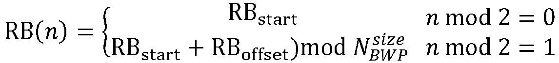 wobei RB(n) die Zielressource angibt, mod eine Modulusoperation angibt,
- Verfahren nach Anspruch 1, wobei die Zeiteinheit von dem Endgerät durch High-Level-Signalisierung oder Signalisierung der physikalischen Schicht bestimmt wird, die von dem Netzwerkgerät übertragen wird.
- Verfahren nach Anspruch 1 oder 2, wobei das Verfahren vor dem Bestimmen (210) einer Zielressource durch ein Endgerät auf der Grundlage eines Index einer Zeiteinheit und von Konfigurationsinformationen ferner Folgendes umfasst:
Empfangen, durch das Endgerät, der vom Netzwerkgerät übertragenen Konfigurationsinformationen, wobei die Konfigurationsinformationen spezifische Informationen für das Endgerät sind. - Datenempfangsverfahren, wobei das Verfahren auf eine Non-Slot-Übertragung angewendet wird und das Verfahren Folgendes umfasst:Übertragen (320), durch ein Netzwerkgerät, von Konfigurationsinformationen an ein Endgerät; undEmpfangen (340), durch das Netzwerkgerät auf einer Zielressource, von Daten, die vom Endgerät übertragen werden;wobei die Zielressource von dem Netzwerkgerät auf der Grundlage eines Index einer Zeiteinheit und der Konfigurationsinformationen bestimmt wird;wobei die Zeiteinheit eine Übertragungsgelegenheit aus mehreren Übertragungsgelegenheiten ist und die Zielressource gemäß der folgenden Formel bestimmt wird:
 wobei RB(n) die Zielressource angibt, mod eine Modulusoperation angibt,
- Endgerät (400), wobei das Endgerät (400) für Non-Slot-Übertragung verwendet wird und das Endgerät (400) Folgendes umfasst:eine Verarbeitungseinheit (410), die so konfiguriert ist, dass sie eine Zielressource basierend auf einem Index einer Zeiteinheit und Konfigurationsinformationen bestimmt; undeine Sende-/Empfangseinheit (420), die so konfiguriert ist, dass sie Daten an ein Netzwerkgerät auf der Zielressource überträgt;wobei die Zeiteinheit eine Übertragungsgelegenheit aus mehreren Übertragungsgelegenheiten ist, und die Verarbeitungseinheit (410) konfiguriert ist, die Zielressource gemäß der folgenden Formel zu bestimmen:
 wobei RB(n) die Zielressource angibt, mod eine Modulusoperation angibt,
- Endgerät (400) nach Anspruch 5, wobei die Zeiteinheit von dem Endgerät (400) durch High-Level-Signalisierung oder Signalisierung der physikalischen Schicht bestimmt wird, die von dem Netzwerkgerät übertragen wird.
- Endgerät (400) nach Anspruch 5 oder 6, wobei die Sende-/Empfangseinheit (420) ferner für Folgendes konfiguriert ist:
Empfangen der vom Netzwerkgerät übertragenen Konfigurationsinformationen, bevor die Verarbeitungseinheit (410) die Zielressource basierend auf einem Index einer Zeiteinheit und Konfigurationsinformationen bestimmt, wobei die Konfigurationsinformationen spezifische Informationen für das Endgerät sind. - Netzwerkgerät (600), wobei das Netzwerkgerät (600) für eine Non-Slot-Übertragung verwendet wird und das Netzwerkgerät (600) Folgendes umfasst:eine Sende-/Empfangseinheit (620), die für Folgendes konfiguriert ist: Senden von Konfigurationsinformationen an ein Endgerät; und Empfangen, auf einer Zielressource, von Daten, die von dem Endgerät übertragen werden;wobei die Zielressource von einer Verarbeitungseinheit (610) des Netzwerkgerätes (600) auf der Grundlage eines Index einer Zeiteinheit und der Konfigurationsinformationen bestimmt wird;wobei die Zeiteinheit eine Übertragungsgelegenheit aus mehreren Übertragungsgelegenheiten ist und die Zielressource gemäß der folgenden Formel bestimmt wird:
 wobei RB(n) die Zielressource angibt, mod eine Modulusoperation angibt,
Applications Claiming Priority (2)
| Application Number | Priority Date | Filing Date | Title |
|---|---|---|---|
| CN2018072169 | 2018-01-10 | ||
| PCT/CN2018/074357 WO2019136778A1 (zh) | 2018-01-10 | 2018-01-26 | 发送数据的方法、接收数据的方法、终端设备和网络设备 |
Publications (3)
| Publication Number | Publication Date |
|---|---|
| EP3737178A1 EP3737178A1 (de) | 2020-11-11 |
| EP3737178A4 EP3737178A4 (de) | 2021-03-10 |
| EP3737178B1 true EP3737178B1 (de) | 2023-07-19 |
Family
ID=67219213
Family Applications (1)
| Application Number | Title | Priority Date | Filing Date |
|---|---|---|---|
| EP18900192.8A Active EP3737178B1 (de) | 2018-01-10 | 2018-01-26 | Datensendeverfahren, datenempfangsverfahren, endgerät und netzwerkvorrichtung |
Country Status (10)
| Country | Link |
|---|---|
| US (1) | US11546913B2 (de) |
| EP (1) | EP3737178B1 (de) |
| JP (1) | JP2021515434A (de) |
| KR (1) | KR20200108314A (de) |
| CN (2) | CN111787520B (de) |
| AU (1) | AU2018401637A1 (de) |
| BR (1) | BR112020014162A2 (de) |
| CA (1) | CA3088215A1 (de) |
| MX (1) | MX2020007484A (de) |
| WO (1) | WO2019136778A1 (de) |
Families Citing this family (3)
| Publication number | Priority date | Publication date | Assignee | Title |
|---|---|---|---|---|
| RU2765986C1 (ru) * | 2018-09-18 | 2022-02-07 | Гуандун Оппо Мобайл Телекоммьюникейшнз Корп., Лтд. | Способ распределения ресурсов, терминал и сетевое устройство |
| EP4224757A4 (de) * | 2020-09-30 | 2023-11-15 | Guangdong Oppo Mobile Telecommunications Corp., Ltd. | Verfahren und vorrichtung zur bestimmung einer frequenzdomänenposition, vorrichtung und speichermedium |
| US20220330295A1 (en) * | 2021-04-13 | 2022-10-13 | Qualcomm Incorporated | Multi-slot transmissions for multi-transmission reception points |
Citations (1)
| Publication number | Priority date | Publication date | Assignee | Title |
|---|---|---|---|---|
| EP2946624B1 (de) * | 2013-03-08 | 2020-10-28 | Huawei Technologies Co., Ltd. | System und verfahren für ein autorisierungsfreies übertragungsschema und basisstation |
Family Cites Families (9)
| Publication number | Priority date | Publication date | Assignee | Title |
|---|---|---|---|---|
| US20120281679A1 (en) * | 2011-05-02 | 2012-11-08 | Renesas Mobile Corporation | RACH communication in cellular system |
| CN105103641B (zh) * | 2014-02-10 | 2019-06-21 | 华为技术有限公司 | Prach资源配置方法及资源配置的获取方法、基站及用户设备 |
| WO2016091185A1 (zh) * | 2014-12-12 | 2016-06-16 | 华为技术有限公司 | 数据传输的方法、基站和用户设备 |
| CN107409413B (zh) * | 2015-04-15 | 2021-06-04 | 苹果公司 | 蜂窝网络中用于机器类型通信的方法和装置 |
| CN106507497B (zh) * | 2015-09-08 | 2020-09-11 | 华为技术有限公司 | 用于上行数据传输的方法、终端设备和网络设备 |
| CN107318086B (zh) * | 2016-04-26 | 2020-03-20 | 华为技术有限公司 | 分配时频资源的方法和装置 |
| US10355743B2 (en) * | 2017-01-27 | 2019-07-16 | Qualcomm Incorporated | Frequency hopping design for large bandwidth allocations in eMTC |
| US10645730B2 (en) * | 2017-04-06 | 2020-05-05 | Huawei Technologies Co., Ltd. | Flexible grant-free resource configuration signaling |
| CN107484175B (zh) * | 2017-08-28 | 2021-01-19 | 海能达通信股份有限公司 | 一种数据传输方法及其基站 |
-
2018
- 2018-01-26 CN CN202010736719.7A patent/CN111787520B/zh active Active
- 2018-01-26 KR KR1020207022873A patent/KR20200108314A/ko not_active Application Discontinuation
- 2018-01-26 CA CA3088215A patent/CA3088215A1/en not_active Abandoned
- 2018-01-26 MX MX2020007484A patent/MX2020007484A/es unknown
- 2018-01-26 WO PCT/CN2018/074357 patent/WO2019136778A1/zh unknown
- 2018-01-26 EP EP18900192.8A patent/EP3737178B1/de active Active
- 2018-01-26 AU AU2018401637A patent/AU2018401637A1/en not_active Abandoned
- 2018-01-26 CN CN201880079628.1A patent/CN111466144A/zh active Pending
- 2018-01-26 JP JP2020538538A patent/JP2021515434A/ja active Pending
- 2018-01-26 BR BR112020014162-3A patent/BR112020014162A2/pt not_active IP Right Cessation
-
2020
- 2020-07-10 US US16/925,823 patent/US11546913B2/en active Active
Patent Citations (1)
| Publication number | Priority date | Publication date | Assignee | Title |
|---|---|---|---|---|
| EP2946624B1 (de) * | 2013-03-08 | 2020-10-28 | Huawei Technologies Co., Ltd. | System und verfahren für ein autorisierungsfreies übertragungsschema und basisstation |
Also Published As
| Publication number | Publication date |
|---|---|
| CN111787520B (zh) | 2022-02-01 |
| EP3737178A4 (de) | 2021-03-10 |
| CN111787520A (zh) | 2020-10-16 |
| US20200351893A1 (en) | 2020-11-05 |
| WO2019136778A1 (zh) | 2019-07-18 |
| BR112020014162A2 (pt) | 2020-12-08 |
| KR20200108314A (ko) | 2020-09-17 |
| CA3088215A1 (en) | 2019-07-18 |
| MX2020007484A (es) | 2020-09-14 |
| JP2021515434A (ja) | 2021-06-17 |
| US11546913B2 (en) | 2023-01-03 |
| EP3737178A1 (de) | 2020-11-11 |
| CN111466144A (zh) | 2020-07-28 |
| AU2018401637A1 (en) | 2020-08-27 |
Similar Documents
| Publication | Publication Date | Title |
|---|---|---|
| CN109565840B (zh) | 探测参考信号传输方法、终端设备和网络设备 | |
| US20200344804A1 (en) | Resource configuration method and communications apparatus | |
| EP3998828A1 (de) | Datensendeverfahren und -vorrichtung dafür | |
| CN111465110B (zh) | 传输数据的方法和终端设备 | |
| EP3768012B1 (de) | Drahtloses kommunikationsverfahren und vorrichtung, chip und system | |
| US11546913B2 (en) | Data transmitting method, data receiving method, terminal device, and network device | |
| EP3379883B1 (de) | Verfahren und mobilstation zur übertragung eines dienstes | |
| CN113068259B (zh) | 无线通信方法和设备 | |
| EP3751940B1 (de) | Drahtloskommunikationsverfahren und -vorrichtung | |
| EP3706497A1 (de) | Datenübertragungsverfahren und -endgerätevorrichtung | |
| TW202041072A (zh) | 通訊方法和終端設備 | |
| US20240090006A1 (en) | Wireless communication method and network device | |
| CN111642015A (zh) | 确定传输资源的方法、终端设备、网络设备和计算机可读介质 | |
| CN107710664B (zh) | 传输数据的方法、终端和基站 | |
| WO2018201344A1 (zh) | 无线通信的方法、终端设备和网络设备 | |
| CN111345082B (zh) | 配置参考信号的方法、终端设备和网络设备 | |
| WO2020199171A1 (zh) | 一种传输参数确定方法及装置、用户设备 |
Legal Events
| Date | Code | Title | Description |
|---|---|---|---|
| STAA | Information on the status of an ep patent application or granted ep patent |
Free format text: STATUS: THE INTERNATIONAL PUBLICATION HAS BEEN MADE |
|
| PUAI | Public reference made under article 153(3) epc to a published international application that has entered the european phase |
Free format text: ORIGINAL CODE: 0009012 |
|
| STAA | Information on the status of an ep patent application or granted ep patent |
Free format text: STATUS: REQUEST FOR EXAMINATION WAS MADE |
|
| 17P | Request for examination filed |
Effective date: 20200806 |
|
| AK | Designated contracting states |
Kind code of ref document: A1 Designated state(s): AL AT BE BG CH CY CZ DE DK EE ES FI FR GB GR HR HU IE IS IT LI LT LU LV MC MK MT NL NO PL PT RO RS SE SI SK SM TR |
|
| AX | Request for extension of the european patent |
Extension state: BA ME |
|
| A4 | Supplementary search report drawn up and despatched |
Effective date: 20210204 |
|
| RIC1 | Information provided on ipc code assigned before grant |
Ipc: H04L 5/00 20060101ALI20210129BHEP Ipc: H04W 72/04 20090101AFI20210129BHEP |
|
| DAV | Request for validation of the european patent (deleted) | ||
| DAX | Request for extension of the european patent (deleted) | ||
| STAA | Information on the status of an ep patent application or granted ep patent |
Free format text: STATUS: EXAMINATION IS IN PROGRESS |
|
| 17Q | First examination report despatched |
Effective date: 20211026 |
|
| GRAP | Despatch of communication of intention to grant a patent |
Free format text: ORIGINAL CODE: EPIDOSNIGR1 |
|
| STAA | Information on the status of an ep patent application or granted ep patent |
Free format text: STATUS: GRANT OF PATENT IS INTENDED |
|
| INTG | Intention to grant announced |
Effective date: 20230209 |
|
| GRAS | Grant fee paid |
Free format text: ORIGINAL CODE: EPIDOSNIGR3 |
|
| GRAA | (expected) grant |
Free format text: ORIGINAL CODE: 0009210 |
|
| STAA | Information on the status of an ep patent application or granted ep patent |
Free format text: STATUS: THE PATENT HAS BEEN GRANTED |
|
| AK | Designated contracting states |
Kind code of ref document: B1 Designated state(s): AL AT BE BG CH CY CZ DE DK EE ES FI FR GB GR HR HU IE IS IT LI LT LU LV MC MK MT NL NO PL PT RO RS SE SI SK SM TR |
|
| REG | Reference to a national code |
Ref country code: GB Ref legal event code: FG4D |
|
| REG | Reference to a national code |
Ref country code: CH Ref legal event code: EP |
|
| REG | Reference to a national code |
Ref country code: DE Ref legal event code: R096 Ref document number: 602018053846 Country of ref document: DE |
|
| REG | Reference to a national code |
Ref country code: IE Ref legal event code: FG4D |
|
| REG | Reference to a national code |
Ref country code: LT Ref legal event code: MG9D |
|
| P01 | Opt-out of the competence of the unified patent court (upc) registered |
Effective date: 20231016 |
|
| REG | Reference to a national code |
Ref country code: NL Ref legal event code: MP Effective date: 20230719 |
|
| REG | Reference to a national code |
Ref country code: AT Ref legal event code: MK05 Ref document number: 1590744 Country of ref document: AT Kind code of ref document: T Effective date: 20230719 |
|
| PG25 | Lapsed in a contracting state [announced via postgrant information from national office to epo] |
Ref country code: NL Free format text: LAPSE BECAUSE OF FAILURE TO SUBMIT A TRANSLATION OF THE DESCRIPTION OR TO PAY THE FEE WITHIN THE PRESCRIBED TIME-LIMIT Effective date: 20230719 |
|
| PG25 | Lapsed in a contracting state [announced via postgrant information from national office to epo] |
Ref country code: GR Free format text: LAPSE BECAUSE OF FAILURE TO SUBMIT A TRANSLATION OF THE DESCRIPTION OR TO PAY THE FEE WITHIN THE PRESCRIBED TIME-LIMIT Effective date: 20231020 |
|
| PG25 | Lapsed in a contracting state [announced via postgrant information from national office to epo] |
Ref country code: IS Free format text: LAPSE BECAUSE OF FAILURE TO SUBMIT A TRANSLATION OF THE DESCRIPTION OR TO PAY THE FEE WITHIN THE PRESCRIBED TIME-LIMIT Effective date: 20231119 |
|
| PG25 | Lapsed in a contracting state [announced via postgrant information from national office to epo] |
Ref country code: SE Free format text: LAPSE BECAUSE OF FAILURE TO SUBMIT A TRANSLATION OF THE DESCRIPTION OR TO PAY THE FEE WITHIN THE PRESCRIBED TIME-LIMIT Effective date: 20230719 Ref country code: RS Free format text: LAPSE BECAUSE OF FAILURE TO SUBMIT A TRANSLATION OF THE DESCRIPTION OR TO PAY THE FEE WITHIN THE PRESCRIBED TIME-LIMIT Effective date: 20230719 Ref country code: PT Free format text: LAPSE BECAUSE OF FAILURE TO SUBMIT A TRANSLATION OF THE DESCRIPTION OR TO PAY THE FEE WITHIN THE PRESCRIBED TIME-LIMIT Effective date: 20231120 Ref country code: NO Free format text: LAPSE BECAUSE OF FAILURE TO SUBMIT A TRANSLATION OF THE DESCRIPTION OR TO PAY THE FEE WITHIN THE PRESCRIBED TIME-LIMIT Effective date: 20231019 Ref country code: LV Free format text: LAPSE BECAUSE OF FAILURE TO SUBMIT A TRANSLATION OF THE DESCRIPTION OR TO PAY THE FEE WITHIN THE PRESCRIBED TIME-LIMIT Effective date: 20230719 Ref country code: LT Free format text: LAPSE BECAUSE OF FAILURE TO SUBMIT A TRANSLATION OF THE DESCRIPTION OR TO PAY THE FEE WITHIN THE PRESCRIBED TIME-LIMIT Effective date: 20230719 Ref country code: IS Free format text: LAPSE BECAUSE OF FAILURE TO SUBMIT A TRANSLATION OF THE DESCRIPTION OR TO PAY THE FEE WITHIN THE PRESCRIBED TIME-LIMIT Effective date: 20231119 Ref country code: HR Free format text: LAPSE BECAUSE OF FAILURE TO SUBMIT A TRANSLATION OF THE DESCRIPTION OR TO PAY THE FEE WITHIN THE PRESCRIBED TIME-LIMIT Effective date: 20230719 Ref country code: GR Free format text: LAPSE BECAUSE OF FAILURE TO SUBMIT A TRANSLATION OF THE DESCRIPTION OR TO PAY THE FEE WITHIN THE PRESCRIBED TIME-LIMIT Effective date: 20231020 Ref country code: FI Free format text: LAPSE BECAUSE OF FAILURE TO SUBMIT A TRANSLATION OF THE DESCRIPTION OR TO PAY THE FEE WITHIN THE PRESCRIBED TIME-LIMIT Effective date: 20230719 Ref country code: AT Free format text: LAPSE BECAUSE OF FAILURE TO SUBMIT A TRANSLATION OF THE DESCRIPTION OR TO PAY THE FEE WITHIN THE PRESCRIBED TIME-LIMIT Effective date: 20230719 |
|
| PG25 | Lapsed in a contracting state [announced via postgrant information from national office to epo] |
Ref country code: PL Free format text: LAPSE BECAUSE OF FAILURE TO SUBMIT A TRANSLATION OF THE DESCRIPTION OR TO PAY THE FEE WITHIN THE PRESCRIBED TIME-LIMIT Effective date: 20230719 |