EP3737112B1 - Headphones with bass enhancement - Google Patents
Headphones with bass enhancement Download PDFInfo
- Publication number
- EP3737112B1 EP3737112B1 EP20173144.5A EP20173144A EP3737112B1 EP 3737112 B1 EP3737112 B1 EP 3737112B1 EP 20173144 A EP20173144 A EP 20173144A EP 3737112 B1 EP3737112 B1 EP 3737112B1
- Authority
- EP
- European Patent Office
- Prior art keywords
- bass port
- end opening
- headphones
- air flow
- chamber
- Prior art date
- Legal status (The legal status is an assumption and is not a legal conclusion. Google has not performed a legal analysis and makes no representation as to the accuracy of the status listed.)
- Active
Links
Images


Classifications
-
- H—ELECTRICITY
- H04—ELECTRIC COMMUNICATION TECHNIQUE
- H04R—LOUDSPEAKERS, MICROPHONES, GRAMOPHONE PICK-UPS OR LIKE ACOUSTIC ELECTROMECHANICAL TRANSDUCERS; DEAF-AID SETS; PUBLIC ADDRESS SYSTEMS
- H04R1/00—Details of transducers, loudspeakers or microphones
- H04R1/20—Arrangements for obtaining desired frequency or directional characteristics
- H04R1/22—Arrangements for obtaining desired frequency or directional characteristics for obtaining desired frequency characteristic only
- H04R1/28—Transducer mountings or enclosures modified by provision of mechanical or acoustic impedances, e.g. resonator, damping means
- H04R1/2803—Transducer mountings or enclosures modified by provision of mechanical or acoustic impedances, e.g. resonator, damping means for loudspeaker transducers
-
- H—ELECTRICITY
- H04—ELECTRIC COMMUNICATION TECHNIQUE
- H04R—LOUDSPEAKERS, MICROPHONES, GRAMOPHONE PICK-UPS OR LIKE ACOUSTIC ELECTROMECHANICAL TRANSDUCERS; DEAF-AID SETS; PUBLIC ADDRESS SYSTEMS
- H04R1/00—Details of transducers, loudspeakers or microphones
- H04R1/20—Arrangements for obtaining desired frequency or directional characteristics
- H04R1/22—Arrangements for obtaining desired frequency or directional characteristics for obtaining desired frequency characteristic only
- H04R1/28—Transducer mountings or enclosures modified by provision of mechanical or acoustic impedances, e.g. resonator, damping means
-
- H—ELECTRICITY
- H04—ELECTRIC COMMUNICATION TECHNIQUE
- H04R—LOUDSPEAKERS, MICROPHONES, GRAMOPHONE PICK-UPS OR LIKE ACOUSTIC ELECTROMECHANICAL TRANSDUCERS; DEAF-AID SETS; PUBLIC ADDRESS SYSTEMS
- H04R1/00—Details of transducers, loudspeakers or microphones
- H04R1/10—Earpieces; Attachments therefor ; Earphones; Monophonic headphones
- H04R1/1041—Mechanical or electronic switches, or control elements
-
- H—ELECTRICITY
- H04—ELECTRIC COMMUNICATION TECHNIQUE
- H04R—LOUDSPEAKERS, MICROPHONES, GRAMOPHONE PICK-UPS OR LIKE ACOUSTIC ELECTROMECHANICAL TRANSDUCERS; DEAF-AID SETS; PUBLIC ADDRESS SYSTEMS
- H04R1/00—Details of transducers, loudspeakers or microphones
- H04R1/10—Earpieces; Attachments therefor ; Earphones; Monophonic headphones
- H04R1/1083—Reduction of ambient noise
Definitions
- the present invention relates to headphones. More particularly, the present invention relates to headphones with acoustic enhancement and method for the same.
- EP3035700A1 and US2016/295315A1 describe a headphone and acoustic characteristic adjustment method.
- US2014/226847A1 discloses an earphone.
- the headphones further include an acoustic chamber configured to prevent ambient noise from substantially mixing with the analog audio reproduction.
- the acoustic chamber substantially encircles and covers a backside of the driver unit except for where the secondary bass port couples to the primary bass port of the driver.
- the acoustic chamber and the secondary bass port are configured for collectively tuning the sound pressure levels in the frequency response and the backside of the driver unit corresponds to an exterior side of the housing.
- the exterior side of the housing is opposite of the interior side of the housing and the second end opening of the primary bass port does not open to the acoustic chamber.
- the headphones have a corresponding frequency response.
- the method includes: 1) providing a driver unit with a housing having an interior side for integrating together a magnet, a diaphragm, and a primary bass port, the primary bass port being substantially surrounded by the magnet and having a primary bass port chamber with a first end opening facing towards the diaphragm and a second end opening facing opposite of the first end opening, the diaphragm being located on a front side of the driver unit and configured for analog audio reproduction; 2) providing a secondary bass port having a secondary bass port chamber with a third end opening and a fourth end opening, the secondary bass port being coupled at the third end opening to the primary bass port at the second end opening, and the fourth end opening having substantially unimpeded air flow, and 3) providing an acoustic chamber configured to prevent ambient noise from substantially mixing with the analog audio reproduction, the acoustic chamber substantially encircling and covering a backside of the driver unit except for where the secondary
- Some of the advantages of the present invention include: 1) efficient tuning of a sound signature; 2) easy adjustability/customization/configuration of the sound signature; 3) easy adaptability to different headphones' hardware configurations; 4) cost savings.
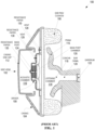
- FIG. 1 is a front view cross-section of a conventional headphone 100.
- the components of headphone 100 that are shown in the front view cross-section i.e., the view of the headphone as worn by a user facing outward
- Headphone 100 may be any type of headphone including but not limited to on-ear, over-the-ear, and in-ear headphones.
- headphone 100 is an over-the-ear type headphone that includes a casing 104 and an ear pad/cushion 106 attached thereon.
- Casing 104 houses a driver 108, an acoustic chamber 110, and optionally (not shown) a printed circuit board assembly (e.g., PCBA for digital signal processing) and battery (e.g., for powering PCBA or driver) within acoustic chamber 110.
- Ear pad/cushion 106 is configured to seal against a user's head and around the user's ear when headphone 100 is worn by the user.
- Ear pad/cushion 106 may be constructed with any pliable material such as foam, rubber, or sponge.
- Casing 104 includes a casing end cap 112 that is removable such that access to the interior and interior components (e.g., PCBA, battery, driver, etc.) of casing 104 is possible.
- Casing 104 may be constructed with any material including but not limited to plastic, metal, non-metals, or any combination of them.
- headphone 200 includes secondary bass port 240 having a secondary bass port chamber 242 with a third end opening 244C and a fourth end opening 244D.
- Secondary bass port 240 is coupled at third end opening 244C to primary bass port 224 at second end opening 244B.
- Fourth end opening 244D has substantially unimpeded air flow.
- secondary bass port 240 is configured for tuning the sound pressure levels in the frequency response. Specifically, secondary bass port 240 is configured for tuning the sound pressure levels within a frequency range of about 100 Hz to 4 kHz in the frequency response. Further, secondary bass port chamber 242 has a corresponding air flow resistance such that lowering the air flow resistance results in increasing sound pressure levels between about 100 Hz and 300 Hz in the frequency response for worse vocal clarity and increasing the air flow resistance results in decreasing sound pressure levels between about 100 Hz and 300 Hz in the frequency response for better vocal clarity. Further details will be provided in FIG. 6 .
- headphones can be defined by their sound signatures, which are related to their frequency response. Tuning the frequency response can be a complicated and time consuming process where consideration must be given to different variables of the headphone. Therefore, it would be beneficial if tuning the frequency response can be limited to fewer considerations or variables. The more variables that can stay constant and/or predictable, the less complicated is the tuning of the frequency response. This is especially true in cases where different design versions of headphones are developed and the constant or predictable variable contributes a known value to the frequency response and hence the sound signature.
- the size of secondary bass port 340 can be fixed or adjusted in advance or in real time to achieve the desired frequency response. Adjustments may be made with a sizable secondary bass port 340.
- secondary bass port 340 may be sizable with a collapsible tube and/or expandable tube. Secondary bass port 340 may be sizable by adjusting any of its physical dimensions (e.g., diameter, length, height, width, etc.). Adjustments can be implemented via local control (e.g., on the headphone) or remote control (e.g., smartphone), mechanical or electrical systems, servo based or non-servo based systems, discrete selection (e.g., pushbuttons) or continuous selection (e.g., slider), or via any combination of these techniques.
- Adjustments may be done with a user switch similar to user switch 248.
- a longer secondary bass port 340 than as shown in FIG. 3 can also be integrated into casing 304, especially in casing end cap 312.
- secondary bass port 340 can be expanded in length by winding/coiling inside casing end cap 312 before having fourth end opening 244D open to air.
- secondary bass port 340 and/or secondary bass port chamber 342 can compensate for sound pressure levels that would otherwise be contributed from other headphone components (e.g., acoustic chamber 110). Therefore, the other headphone components can be minimized and the overall headphone size reduced.
- conventional acoustic chamber 110 requires a larger volume and size for a larger bass level.
- the bass level is correspondingly reduced. Accordingly, the present invention is advantageously able to generate the larger bass level even for a smaller headphone with the implementation of acoustic chamber 210 of smaller volume and size, secondary bass port 240/340, and secondary bass port chamber 242/342.
- user switch 402 corresponds to three discrete selections, which are implemented by selection buttons A, B, and C.
- Selection button A corresponds to an opened bass port hole 404 (e.g., when no air flow resistance is applied at fourth end opening 244D of secondary bass port 240, 340).
- Selection button C corresponds to a closed bass port hole 406 (e.g., when maximum air flow resistance is applied at fourth end opening 244D of secondary bass port 240, 340).
- Selection button B corresponds to a bass port hole with air flow resistor applied 408 (e.g., when any degree of air flow resistance is applied at fourth end opening 244D via air flow resistor 230 of secondary bass port 240, 340).
- the present invention covers any number of selection buttons corresponding to any number/level of air flow resistance applications/implementations.
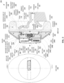
- FIG. 5 is a diagram 500 showing sound pressure levels based on varying air flow resistance at a secondary bass port end opening according to various embodiments of the present invention.
- Diagram 500 shows a sound pressure level (dB) vs. frequency (Hz) plot based on varying air flow resistance at a secondary bass port end opening. The plot is illustrative but not exhaustive. The effect of vary air flow resistance at a secondary bass port end opening is shown in diagram 500. Specifically, by applying different air flow resistances at end openings of secondary bass port 240, 340, different corresponding sound pressure levels within a frequency range in the frequency response can be achieved.
- secondary bass port 240, 340 or secondary bass port chamber 242, 342 has a corresponding air flow resistance such that lowering the air flow resistance results in increasing sound pressure levels between about 100 Hz and 300 Hz in the frequency response for worse vocal clarity and increasing the air flow resistance results in decreasing sound pressure levels between about 100 Hz and 300 Hz in the frequency response for better vocal clarity.
- the lowering or increasing of air flow resistance is due to varying the length of secondary bass port 240, 340.
- a plot curve having optimized vocal clarity may correspond to a secondary bass port 240, 340 with a length for increasing the sound pressure levels within a vocal clarity range 614 (e.g., 100 Hz to 300 Hz) and/or increasing the sound pressure levels within other mid-range frequencies (e.g., above 300 Hz to 1.5 kHz or 4 kHz) in the frequency response of headphone 200, 300.
- the midpoint between the peak and trough of plot curve for optimized vocal clarity is at about 300 Hz.
- Vocal clarity range 614 may encompass portions of upper bass range 610 (e.g., 100 Hz to 200 Hz) and lower mid-range (e.g., above 200 Hz to 300 Hz) of mid-range 612 (e.g., 200 Hz to 4 kHz).
- upper bass range 610 e.g., 100 Hz to 200 Hz
- lower mid-range e.g., above 200 Hz to 300 Hz
- mid-range 612 e.g., 200 Hz to 4 kHz.
- plot curve 606 shows an increase (e.g., 6 dB to 10 dB) of the sound pressure levels within vocal clarity range 614 (e.g., 100 Hz to 300 Hz) and an increase (e.g., 0 dB to ⁇ 6 dB) of the sound pressure levels within the mid-range (e.g., above 300 Hz to 1.5 kHz) in the frequency response of headphone 200, 300.
- an increase e.g., 6 dB to 10 dB
- the sound pressure levels within vocal clarity range 614 e.g., 100 Hz to 300 Hz
- an increase e.g., 0 dB to ⁇ 6 dB
- plot curve 608 shows an increase (e.g., 9 dB to 10 dB) of the sound pressure levels within vocal clarity range 614 (e.g., 100 Hz to 300 Hz) and an increase (e.g., 0 dB to ⁇ 9 dB) of the sound pressure levels within the mid-range (e.g., above 300 Hz to 1.5 kHz) in the frequency response of headphone 200, 300.
- plot curve 606 may be deemed to have a better balance of tuning the sound pressure levels in the frequency response for optimized vocal clarity.
Landscapes
- Physics & Mathematics (AREA)
- Engineering & Computer Science (AREA)
- Acoustics & Sound (AREA)
- Signal Processing (AREA)
- Health & Medical Sciences (AREA)
- Otolaryngology (AREA)
- Headphones And Earphones (AREA)
- Circuit For Audible Band Transducer (AREA)
Description
- The present invention relates to headphones. More particularly, the present invention relates to headphones with acoustic enhancement and method for the same.
- Audio reproduction devices include headphones for audio playback. There are many headphones available for a user to choose from. Most headphones are classified with respect to their sound signatures that are fixed. However, the user may want to adjust the sound signature based on a particular situation or personal preference. Therefore, there is a need for easily adjusting the sound signature by the user.
- Further, in order to achieve a particular sound signature, tuning the headphone is required. Tuning is often complicated and time consuming. As such, changing the headphone design requires very much consideration. Therefore, there is a need to make tuning more efficient.
- Accordingly, it is desirable to provide at least an apparatus with acoustic enhancement and method for the same to address the above needs.
-
EP3035700A1 andUS2016/295315A1 describe a headphone and acoustic characteristic adjustment method.US2014/226847A1 discloses an earphone. - In one aspect of the invention, headphones with acoustic enhancement are provided in accordance with claim 1. Further aspect and preferred embodiments are set out in claim 2 et seq. The headphones have a corresponding frequency response and include: 1) a driver unit with a housing having an interior side for integrating together a magnet, a diaphragm, and a primary bass port, the primary bass port being substantially surrounded by the magnet and having a primary bass port chamber with a first end opening facing towards the diaphragm and a second end opening facing opposite of the first end opening, the diaphragm being located on a front side of the driver unit and configured for analog audio reproduction; and 2) a secondary bass port having a secondary bass port chamber with a third end opening and a fourth end opening, the secondary bass port being coupled at the third end opening to the primary bass port at the second end opening, and the fourth end opening having substantially unimpeded air flow.
- The headphones further include an acoustic chamber configured to prevent ambient noise from substantially mixing with the analog audio reproduction. The acoustic chamber substantially encircles and covers a backside of the driver unit except for where the secondary bass port couples to the primary bass port of the driver. The acoustic chamber and the secondary bass port are configured for collectively tuning the sound pressure levels in the frequency response and the backside of the driver unit corresponds to an exterior side of the housing. The exterior side of the housing is opposite of the interior side of the housing and the second end opening of the primary bass port does not open to the acoustic chamber.
- A first air flow resistor may be controllable to apply different air flow resistances at the fourth end opening of the secondary bass port; a second air flow resistor is configured to apply a fixed air flow resistance at either the second end opening of the primary bass port or third end opening of the secondary bass port; the first and second air flow resistors are of a gas permeable construction; the gas permeable construction including paper, cloth, foam, mesh, or felt; or application of different air flow resistances at the fourth end opening of the secondary bass port results in different sound pressure levels within a frequency range of about 20 Hz to 1.5 kHz in the frequency response. Some embodiments have the headphones further include a user switch for controlling in real time the first air flow resistor's application of different air flow resistances at the fourth end opening of the secondary bass port, the different air flow resistances being incremental or continuous values.
- The secondary bass port may be sizable in real time; the secondary bass port is configured for tuning the sound pressure levels in the frequency response; the secondary bass port is configured for tuning the sound pressure levels within a frequency range of about 100 Hz to 4 kHz in the frequency response; or the secondary bass port chamber has a corresponding air flow resistance such that lowering the air flow resistance results in increasing sound pressure levels between about 100Hz and 300 Hz in the frequency response for worse vocal clarity and increasing the air flow resistance results in decreasing sound pressure levels between about 100 Hz and 300 Hz in the frequency response for better vocal clarity.
- The secondary bass port may include multiple sections that divide the secondary bass port chamber into sub-chambers, each sub-chamber having a different cross sectional area; at least two of the multiple sections are constructed from different materials, the material including plastic, ethylene-vinyl acetate (EVA) felt, metal, non-metal, rubber, foam, or sponge; the driver unit is a dynamic driver; the apparatus including in-ear headphones, on-ear headphones, over-ear headphones, open-back headphones, semi-open back headphones, or closed-back headphones; or the primary bass port is a substantially straight tube and the secondary bass port is a hollow structure of substantially any shape including a straight tube, a winding tube, a straight/winding polygonal cross sectional hollow structure, a straight/winding cylindrical hollow structure, a flare out tube, or any combination of these.
- Further described is a method for headphones with acoustic enhancement according to
claim 10. The headphones have a corresponding frequency response. The method includes: 1) providing a driver unit with a housing having an interior side for integrating together a magnet, a diaphragm, and a primary bass port, the primary bass port being substantially surrounded by the magnet and having a primary bass port chamber with a first end opening facing towards the diaphragm and a second end opening facing opposite of the first end opening, the diaphragm being located on a front side of the driver unit and configured for analog audio reproduction; 2) providing a secondary bass port having a secondary bass port chamber with a third end opening and a fourth end opening, the secondary bass port being coupled at the third end opening to the primary bass port at the second end opening, and the fourth end opening having substantially unimpeded air flow, and 3) providing an acoustic chamber configured to prevent ambient noise from substantially mixing with the analog audio reproduction, the acoustic chamber substantially encircling and covering a backside of the driver unit except for where the secondary bass port couples to the primary bass port of the driver, wherein the acoustic chamber and the secondary bass port are configured for collectively tuning the sound pressure levels in the frequency response and the backside of the driver unit corresponds to an exterior side of the housing, the exterior side of the housing being opposite of the interior side of the housing, wherein the second end opening of the primary bass port does not open to the acoustic chamber. - Some of the advantages of the present invention include: 1) efficient tuning of a sound signature; 2) easy adjustability/customization/configuration of the sound signature; 3) easy adaptability to different headphones' hardware configurations; 4) cost savings. These and other features and advantages of the present invention are described below with reference to the drawings.
-
-
FIG. 1 is a front view cross-section of a conventional headphone. -
FIG. 2 is a front view cross-section of a headphone with acoustic enhancement based on a (relatively shorter) secondary bass port according to various embodiments of the present invention. -
FIG. 3 is a front view cross-section of a headphone with acoustic enhancement based on a (relatively longer) secondary bass port according to various embodiments of the present invention. -
FIG. 4 is an illustration of a user switch for controlling air flow resistance at a secondary bass port according to various embodiments of the present invention. -
FIG. 5 is a diagram showing sound pressure levels based on varying air flow resistance at a secondary bass port end opening according to various embodiments of the present invention. -
FIG. 6 is a diagram showing sound pressure levels based on varying air flow resistance at a secondary bass port by varying its size according to various embodiments of the present invention. -
FIG. 7 is a flow diagram for an apparatus with acoustic enhancement according to various embodiments of the present invention. - Reference will now be made in detail to preferred embodiments of the invention. Examples of the preferred embodiments are illustrated in the accompanying drawings. While the invention will be described in conjunction with these preferred embodiments, it will be understood that it is not intended to limit the invention to such preferred embodiments. The scope of protection is solely defined by the appended claims.
- In the following description, numerous specific details are set forth in order to provide a thorough understanding of the present invention. In other instances, well known mechanisms have not been described in detail in order not to unnecessarily obscure the present invention.
- It should be noted herein that throughout the various drawings like numerals refer to like parts. The various drawings illustrated and described herein are used to illustrate various features of the invention. To the extent that a particular feature is illustrated in one drawing and not another, except where otherwise indicated or where the structure inherently prohibits incorporation of the feature, it is to be understood that those features may be adapted to be included in the embodiments represented in the other figures, as if they were fully illustrated in those figures. Unless otherwise indicated, the drawings are not necessarily to scale. Any dimensions provided on the drawings are not intended to be limiting as to the scope of the invention but merely illustrative.
-
FIG. 1 is a front view cross-section of aconventional headphone 100. The components ofheadphone 100 that are shown in the front view cross-section (i.e., the view of the headphone as worn by a user facing outward) are typically symmetrical and/or round in shape from aside view perspective 102. Headphone 100 may be any type of headphone including but not limited to on-ear, over-the-ear, and in-ear headphones. As shown,headphone 100 is an over-the-ear type headphone that includes acasing 104 and an ear pad/cushion 106 attached thereon. Casing 104 houses adriver 108, anacoustic chamber 110, and optionally (not shown) a printed circuit board assembly (e.g., PCBA for digital signal processing) and battery (e.g., for powering PCBA or driver) withinacoustic chamber 110. Ear pad/cushion 106 is configured to seal against a user's head and around the user's ear whenheadphone 100 is worn by the user. Ear pad/cushion 106 may be constructed with any pliable material such as foam, rubber, or sponge. Casing 104 includes a casing end cap 112 that is removable such that access to the interior and interior components (e.g., PCBA, battery, driver, etc.) ofcasing 104 is possible.Casing 104 may be constructed with any material including but not limited to plastic, metal, non-metals, or any combination of them. - When
headphone 100 is under an operation mode, acoustical audio output signals are generated bydriver 108 from electrical audio input signals and projected into alistening chamber 114 formed by some combination ofcasing 104, ear pad/cushion 106,driver 108, the user's head, and the user's ear (includingpinna 116,concha 118,ear canal 120, eardrum 122). Chambers are typically void spaces with specific pressures when the headphone is under the operation mode such as when the driver is generating acoustical audio output signals from electrical audio input signals. The generation of acoustical audio output signals generally coincides with the movement of the driver's diaphragm whereby acoustical audio output signals propagate from driver 108 (via diaphragm) into listeningchamber 114 and are received byeardrum 122 for user interpretation and listening enjoyment. - Headphones can be defined by their sound signatures, which are related to their frequency response. Tuning the frequency response can be a complicated and time consuming process where consideration must be given to different variables of the headphone design such as the kind of materials used in its construction, the volume and pressure in the chambers in the casing (e.g.
acoustic chamber 110, bass port chamber 126) and listeningchamber 114, the size and number of vent holes 128, the type ofresistance paper 130 used at vent holes 128 or bass port 124 (may also be called dome vent), whether the headphone is open back or closed back type, anddriver 108 specification. Therefore, it would be beneficial to simplify the tuning process in order to save time and resources. -
FIG. 2 is a front view cross-section of aheadphone 200 with acoustic enhancement based on asecondary bass port 240 according to various embodiments of the present invention. The components ofheadphone 200 that are shown in the front view cross-section (i.e., the view of the headphone as worn by a user facing outward) are typically symmetrical and/or round in shape from aside view perspective 202.Headphone 200 may be any type of headphone including but not limited to on-ear, over-the-ear, in-ear, closed-back, semi-open back, and open-back headphones. As shown,headphone 200 is an over-the-ear type headphone that includes acasing 204 and an ear pad/cushion 206 attached thereon. Casing 204 is configured to house adriver 208, anacoustic chamber 210, and optionally a printed circuit board assembly 252 (e.g., PCBA for digital signal processing) and battery 254 (e.g., for poweringPCBA 252 or driver 208) in chamber(s) separate fromacoustic chamber 210. In general,driver 208 is a dynamic driver. - Ear pad/
cushion 206 is generally configured to seal against a user's head and around the user's ear whenheadphone 200 is worn by the user. Ear pad/cushion 206 may be constructed with any pliable material such as foam, rubber, sponge, or any suitable material known by those skilled in the art. Casing 204 may or may not include a casing end cap 212 (also called back cap) that could be non-removable or removable such that access to the interior and interior components (e.g.,driver 208, etc.) ofcasing 204 is possible. Casing 204 may have rigid portions and/or flexible portions and be constructed with any material including but not limited to plastic, metal, non-metal, rubber, or any combination of them. Casingend cap 212 may integrate within or complement separatelyother headphone 300 components (e.g.,baffle 256, secondary bass port 240). For example, casingend cap 212 may be constructed together withbaffle 256 andsecondary bass port 240 or constructed separately for attachment overbaffle 256 andsecondary bass port 240. - When
headphone 200 is under an operation mode, acoustical audio output signals are generated bydriver 208 from electrical audio input signals and projected into a listeningchamber 214 formed by some combination ofcasing 204, ear pad/cushion 206,driver 208, the user's head, and the user's ear (includingpinna 116,concha 118,ear canal 120, eardrum 122). Chambers are typically void spaces with specific pressures or differential pressures whenheadphone 200 is under the operation mode such as whendriver 208 is generating acoustical audio output signals from electrical audio input signals. As such, each chamber may have a different pressure or differential pressure during an operational mode. The generation of acoustical audio output signals generally coincides with the movement of the driver'sdiaphragm 238 whereby acoustical audio output signals propagate from driver 208 (via diaphragm 238) into listeningchamber 214 and are received byeardrum 122 for user interpretation and listening enjoyment. - According to various embodiments,
headphone 200 is provided with acoustic enhancements and a corresponding frequency response. To elaborate,headphone 200 includesdriver 208 with a housing 232 having aninterior side 232A for integrating together amagnet 236,diaphragm 238, and aprimary bass port 224.Primary bass port 224 is substantially surrounded/encircled bymagnet 236 and has a primarybass port chamber 226 with afirst end opening 244A facing towardsdiaphragm 238 and a second end opening 244B facing opposite offirst end opening 244A.Diaphragm 238 is located on afront side 234 ofdriver 208 and configured for analog audio reproduction. In addition,headphone 200 includessecondary bass port 240 having a secondarybass port chamber 242 with a third end opening 244C and afourth end opening 244D.Secondary bass port 240 is coupled at third end opening 244C toprimary bass port 224 at second end opening 244B.Fourth end opening 244D has substantially unimpeded air flow. - Generally,
secondary bass port 240 is a hollow structure of substantially any shape such as a straight tube, a winding tube, a straight/winding polygonal cross sectional hollow structure, a straight/winding cylindrical hollow structure, a flare out tube, or any combination of these shapes.Secondary bass port 240 may include multiple sections that divide secondarybass port chamber 242 into sub-chambers. Each sub-chamber may have a different cross sectional area. The multiple sections may be constructed from different materials such as plastic, ethylene-vinyl acetate (EVA) felt 246, metal, non-metal, rubber, foam, or sponge. Further,secondary bass port 240 may be separate from or integrated withbaffle 256, which could be used to form part ofacoustic chamber 210. Althoughprimary bass port 224 is substantially a straight tube, it may also share some of the aforementioned characteristics ofsecondary bass port 240. - According to a preferred embodiment,
secondary bass port 240 is configured for tuning the sound pressure levels in the frequency response. Specifically,secondary bass port 240 is configured for tuning the sound pressure levels within a frequency range of about 100 Hz to 4 kHz in the frequency response. Further, secondarybass port chamber 242 has a corresponding air flow resistance such that lowering the air flow resistance results in increasing sound pressure levels between about 100 Hz and 300 Hz in the frequency response for worse vocal clarity and increasing the air flow resistance results in decreasing sound pressure levels between about 100 Hz and 300 Hz in the frequency response for better vocal clarity. Further details will be provided inFIG. 6 . -
Acoustic chamber 210 is configured to prevent ambient noise from substantially mixing with the analog audio reproduction.Acoustic chamber 210 substantially surrounds/encircles and covers abackside 232B ofdriver 208 except for wheresecondary bass port 240 couples toprimary bass port 224 ofdriver 208.Backside 232B ofdriver 208 corresponds to anexterior side 232B of housing 232, which is opposite ofinterior side 232A of housing 232. In a preferred embodiment, second end opening 244B ofprimary bass port 224 does not open toacoustic chamber 210.Acoustic chamber 210 andsecondary bass port 240 are configured for separately or collectively tuning the sound pressure levels in the frequency response. Advantageously,acoustic chamber 210 can effectively be an isolation chamber where outside noise does not get in (or substantially prevented from getting in) and sound insideheadphone 200 does not get out (or substantially prevented from getting out). It should be noted, however, thatacoustic chamber 210 can be optional inheadphone 200 and that aspects of the present invention can be implemented withoutacoustic chamber 210. -
Acoustic chamber 210 may also usevent holes 228 to balance the air pressure in listeningchamber 214 and to modulate/regulatediaphragm 238. Vent holes 228 allow air to leak betweenacoustic chamber 210 anddiaphragm 238 in order to maintain the proper tension ofdiaphragm 238. As such,acoustic chamber 210 may function to modulate/regulatediaphragm 238. -
Headphone 200 may also includeair flow resistors 230. For example, a firstair flow resistor 230 is controllable to apply different/variable air flow resistances at fourth end opening 244D ofsecondary bass port 240. A secondair flow resistor 230 is configured to apply an air flow resistance at either second end opening 244B ofprimary bass port 224 or third end opening 244C ofsecondary bass port 240. First and secondair flow resistors 230 may be of a gas permeable construction such as damping material, paper, cloth, foam, mesh, and felt. In general,air flow resistor 230 may be used to adjust the bass levels in the frequency response. Therefore,air flow resistor 230 may be of any number, thickness, or type.Headphone 200 may also excludeair flow resistors 230. For example, there could be differential pressure between port end openings due to Helmholtz resonance (port resonance) where it is possible to have noair flow resistors 230 at end openings ofprimary bass port 224 andsecondary bass port 240. -
Headphone 200 may further include a user switch 248 for controlling in real time first air flow resistor's 230 application of different air flow resistances at fourth end opening 244D ofsecondary bass port 240. Generally, the smaller the air flow resistance, the stronger the bass level in the frequency response. The different air flow resistances can be adjusted incrementally over group of values or continuously in sequential values. User switch 248 may be any suitable controller for adjusting the air flow resistance atfourth end opening 244D. It may be implemented locally (e.g., on the headphone) or remotely (e.g., smartphone), mechanically or electrically, servo based or non-servo based, discrete selection (e.g., pushbuttons) or continuous selection (e.g., slider), or using any combination of these techniques. By applying different air flow resistances at fourth end opening 244D ofsecondary bass port 240, different corresponding sound pressure levels within a frequency range of about 20 Hz to 1.5 kHz in the frequency response can be achieved. - Open back type headphones generally do not have a restrictive barrier for sealing in the audio playback and keeping out ambient noise from penetrating the user's listening experience. On the other hand, closed back type headphones generally have a restrictive barrier for sealing in the audio playback while keeping out ambient noise from penetrating the user's listening experience. For example, a closed back type headphone may have its ear pad covered by a shell that houses the driver and hinders the transmission of sound through it. As such,
headphone 200 can be viewed as a hybrid between an open back type headphone (for havingholes 250 in casingend cap 212 orsecondary bass port 240 open to free air) and a closed back type headphone (for havingacoustic chamber 210 substantially covering driver 208). Althoughsecondary bass port 240 may open to free air with or without air flow resistor 230 (e.g., viaholes 250 in casingend cap 212 or directly for the purpose of achieving the desired tuning of the headphone's frequency response), the sound escaping fromsecondary bass port 240 can be or in fact be negligible (e.g., due to the level or frequency range of sound escaping that can be detected by another person) such thatheadphone 200 may beneficially and effectively function in terms of noise isolation as a closed back type headphone even though it may be an open back type headphone. In some embodiments,headphone 200 is a semi-open back type headphone that allows for some sound isolation and a little sound leakage. - As noted earlier, headphones can be defined by their sound signatures, which are related to their frequency response. Tuning the frequency response can be a complicated and time consuming process where consideration must be given to different variables of the headphone. Therefore, it would be beneficial if tuning the frequency response can be limited to fewer considerations or variables. The more variables that can stay constant and/or predictable, the less complicated is the tuning of the frequency response. This is especially true in cases where different design versions of headphones are developed and the constant or predictable variable contributes a known value to the frequency response and hence the sound signature. For example, in contrast to
conventional headphone 100, which includesacoustic chamber 110 designed to accommodate other components such as a PCBA or battery,acoustic chamber 210 is designed to be standalone/isolated where its volume would remain constant (note:PCBA 252 andbattery 254 are housed separately from acoustic chamber 210) and not be affected by accommodating other components within it. This is especially significant if the PCBA or battery size changes after the headphone design has already been fixed or set. As such,acoustic chamber 210 allows the flexibility to change the PCBA or battery without affecting its volume, but keep its contribution to the frequency response and sound signature relatively constant or known. Further,acoustic chamber 210 allows for the independent tuning of secondary bass port (e.g., adjusting the length and/or applying air flow resistance at end openings without needing to also tuning/retuning acoustic chamber 210) for bass or vocal enhancement in the headphone's frequency response. -
FIG. 3 is a front view cross-section of aheadphone 300 with acoustic enhancement based on asecondary bass port 340 according to various embodiments of the present invention.Headphone 300 is similar toheadphone 200 except for a few differences. As such, many aspects and benefits ofheadphone 200 apply toheadphone 300. However, one of the main differences is thatheadphone 300 includes acasing 304 withsecondary bass port 340 that is relatively longer thansecondary bass port 240 inheadphone 200. Despite these differences,secondary bass ports - The size of
secondary bass port 340 can be fixed or adjusted in advance or in real time to achieve the desired frequency response. Adjustments may be made with a sizablesecondary bass port 340. For example,secondary bass port 340 may be sizable with a collapsible tube and/or expandable tube.Secondary bass port 340 may be sizable by adjusting any of its physical dimensions (e.g., diameter, length, height, width, etc.). Adjustments can be implemented via local control (e.g., on the headphone) or remote control (e.g., smartphone), mechanical or electrical systems, servo based or non-servo based systems, discrete selection (e.g., pushbuttons) or continuous selection (e.g., slider), or via any combination of these techniques. Adjustments may be done with a user switch similar to user switch 248. A longersecondary bass port 340 than as shown inFIG. 3 can also be integrated intocasing 304, especially in casingend cap 312. For instance,secondary bass port 340 can be expanded in length by winding/coiling inside casingend cap 312 before havingfourth end opening 244D open to air. - Similar to casing
end cap 212, casingend cap 312 may integrate within or complement separatelyother headphone 300 components (e.g.,baffle 356, secondary bass port 340). For example, casingend cap 312 may be constructed together withbaffle 356 andsecondary bass port 340 or constructed separately for attachment overbaffle 356 andsecondary bass port 340. Further,secondary bass port 340 may be separate from or integrated withbaffle 356, which could be used to form part ofacoustic chamber 210. - Due to the relatively longer
secondary bass port 340 thansecondary bass port 240, corresponding secondary bass port chamber 342 is relatively longer than secondarybass port chamber 242. As such, a larger volume of secondary bass port chamber 342 or larger corresponding air flow resistance can result in a frequency response forheadphone 300 that is different fromheadphone 200. According to a preferred embodiment,secondary bass port 340 is configured for tuning the sound pressure levels in the frequency response. Specifically,secondary bass port 340 is configured for tuning the sound pressure levels within a frequency range of about 100 Hz to 4 kHz in the frequency response. Further, secondary bass port chamber 342 has a corresponding air flow resistance such that lowering the air flow resistance results in increasing sound pressure levels between about 100Hz and 300 Hz in the frequency response for worse vocal clarity and increasing the air flow resistance results in decreasing sound pressure levels between about 100 Hz and 300 Hz in the frequency response for better vocal clarity. Further details will be provided inFIG. 6 . - By being able to adjust or configure the sound pressure levels in the frequency response,
secondary bass port 340 and/or secondary bass port chamber 342 can compensate for sound pressure levels that would otherwise be contributed from other headphone components (e.g., acoustic chamber 110). Therefore, the other headphone components can be minimized and the overall headphone size reduced. For example, conventionalacoustic chamber 110 requires a larger volume and size for a larger bass level. However, if conventionalacoustic chamber 110 is reduced in volume and size for a smaller headphone, the bass level is correspondingly reduced. Accordingly, the present invention is advantageously able to generate the larger bass level even for a smaller headphone with the implementation ofacoustic chamber 210 of smaller volume and size,secondary bass port 240/340, and secondarybass port chamber 242/342. - Due to
secondary bass port 340 extending throughcasing end cap 312, casing 304 includes casingend cap 312 with optional chamber(s) forhousing PCBA 252 andbattery 254. The chamber(s) are configured to integrate intocasing end cap 312 such that the walls that form the chamber(s) may also be used to form a portion ofsecondary bass port 340 and/orbaffle 356. As shown, only a single chamber housesPCBA 252 andbattery 254 where the inner wall forms the cylindrical shape ofsecondary bass port 340. Further, EVA felt 246 forms another portion of the cylindrical shape ofsecondary bass port 340 and connects toprimary bass port 224. EVA felt 246 also provides advantageous sealing properties. - The present invention's ability to tune the frequency response by adjusting the size (e.g., length, diameter, width, height, etc.) of
secondary bass port 240/340 and/or applying air flow resistances at end openings ofsecondary bass port 240/340 allows for large tuning adjustments as well as large incremental tuning adjustments; thereby, making large tuning adjustments more efficient. In contrast,traditional headphone 100 only allows for small tuning adjustments as well as small incremental tuning adjustments. However, the present invention is configurable to also make small tuning adjustments as well as small incremental tuning adjustments; thereby, making overall tuning more efficient. Adjusting a dimension of the size may compensate for another dimension of the size towards its contribution to the acoustic enhancement. For example, an increased diameter can be used in place of a decreased length and vice versa for adjusting the frequency response. - Since there are different components in
headphone headphone -
FIG. 4 is anillustration 400 of auser switch 402 for controlling air flow resistance at a secondary bass port (e.g., 240, 340) according to various embodiments of the present invention. User switch 402 (e.g., 248) may be any suitable controller for adjusting in real time the air flow resistance atfourth end opening 244D and/or other end openings (e.g., 244B, 244C). Different air flow resistances can be adjusted incrementally over group of values or continuously in sequential values. It may be implemented locally (e.g., on the headphone) or remotely (e.g., smartphone), mechanically or electrically, servo based or non-servo based, discrete selection (e.g., pushbuttons, toggle buttons, etc.) or continuous selection (e.g., slider), voice activated or non-voice activated, contact or non-contact controls, or using any combination of these techniques. By applying different air flow resistances at end openings (e.g., at fourth end opening 244D ofsecondary bass port 240, 340), different corresponding sound pressure levels within a frequency range (e.g., about 20 Hz to 1.5 kHz) in the frequency response can be achieved as discussed below with reference toFIG. 5 . - As shown,
user switch 402 corresponds to three discrete selections, which are implemented by selection buttons A, B, and C. Selection button A corresponds to an opened bass port hole 404 (e.g., when no air flow resistance is applied at fourth end opening 244D ofsecondary bass port 240, 340). Selection button C corresponds to a closed bass port hole 406 (e.g., when maximum air flow resistance is applied at fourth end opening 244D ofsecondary bass port 240, 340). Selection button B corresponds to a bass port hole with air flow resistor applied 408 (e.g., when any degree of air flow resistance is applied atfourth end opening 244D viaair flow resistor 230 ofsecondary bass port 240, 340). However, it should be noted that the present invention covers any number of selection buttons corresponding to any number/level of air flow resistance applications/implementations. - Air flow resistance maybe applied via one or more
air flow resistor 230.Air flow resistor 230 may be any mechanism suitable for applying a corresponding resistance to air flow.Air flow resistor 230 can be of a gas permeable construction (e.g., paper, cloth, foam, mesh, felt, and etc.) or a gas non-permeable construction (e.g., plastic, metal, and etc.). As such, a gas permeable or non-permeable constructedair flow resistor 230 can be configured to incrementally cover an end opening (e.g., 244C, 244D) insecondary bass port air flow resistor 230 can be configured to continuously cover an end opening insecondary bass port - In a preferred embodiment, a first
air flow resistor 230 is controllable to apply different air flow resistances at fourth end opening 244D ofsecondary bass port air flow resistor 230 is configured to apply a fixed air flow resistance at either second end opening 244B ofprimary bass port 224 or third end opening 244C ofsecondary bass port -
FIG. 5 is a diagram 500 showing sound pressure levels based on varying air flow resistance at a secondary bass port end opening according to various embodiments of the present invention. Diagram 500 shows a sound pressure level (dB) vs. frequency (Hz) plot based on varying air flow resistance at a secondary bass port end opening. The plot is illustrative but not exhaustive. The effect of vary air flow resistance at a secondary bass port end opening is shown in diagram 500. Specifically, by applying different air flow resistances at end openings ofsecondary bass port - In a preferred embodiment, different air flow resistances at fourth end opening 244D of
secondary bass port headphone secondary bass port 240, 340) inFIG. 4 .Plot curve 504 corresponds to selection button C of a closed bass port hole 406 (e.g., when maximum air flow resistance is applied at fourth end opening 244D ofsecondary bass port 240, 340) inFIG. 4 .Plot curve 506 corresponds to selection button B of a bass port hole with air flow resistor applied 408 (e.g., when any degree of air flow resistance is applied atfourth end opening 244D viaair flow resistor 230 ofsecondary bass port 240, 340) inFIG. 4 . - Notably, plot curve 502 shows the most increase (e.g., 10 dB) to sound pressure levels within a range of about 20 Hz to 1.5 kHz in the frequency response of
headphone Plot curve 504 shows the least increase (e.g., none) to sound pressure levels within a range of about 20 Hz to 1.5 kHz in the frequency response ofheadphone plot curve 506 shows an increase (e.g., 5 dB) to sound pressure levels within a range of about 20 Hz to 1.5 kHz in the frequency response ofheadphone headphone secondary bass port -
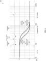
FIG. 6 is a diagram 600 showing sound pressure levels based on varying air flow resistance at a secondary bass port by varying its size according to various embodiments of the present invention. Diagram 600 shows a sound pressure level (dB) vs. frequency (Hz) plot based on varying air flow resistance at a secondary bass port by varying its size. The plot is illustrative but not exhaustive. The effect of vary air flow resistance at a secondary bass port by varying its size is shown in diagram 600. For example, by applying different air flow resistances via varying the length ofsecondary bass port secondary bass port fourth end opening 244D. - According to a preferred embodiment,
secondary bass port secondary bass port secondary bass port secondary bass port bass port chamber 242, 342 has a corresponding air flow resistance such that lowering the air flow resistance results in increasing sound pressure levels between about 100 Hz and 300 Hz in the frequency response for worse vocal clarity and increasing the air flow resistance results in decreasing sound pressure levels between about 100 Hz and 300 Hz in the frequency response for better vocal clarity. The lowering or increasing of air flow resistance is due to varying the length ofsecondary bass port - To further elaborate,
plot curve 606 corresponds to a longer port tube (i.e.,secondary bass port 240, 340) such as shown inFIG. 3 . Plot curve 608 corresponds to a shorter port tube (i.e.,secondary bass port 240, 340) such as shown inFIG. 2 . As such, increasing the length ofsecondary bass port air flow resistance 602; hence, shifting a plot curve left on diagram 600. Yet, decreasing the length ofsecondary bass port air flow resistance 604; hence, shifting a plot curve right on diagram 600. By adjusting or configuring the length ofsecondary bass port secondary bass port headphone Vocal clarity range 614 may encompass portions of upper bass range 610 (e.g., 100 Hz to 200 Hz) and lower mid-range (e.g., above 200 Hz to 300 Hz) of mid-range 612 (e.g., 200 Hz to 4 kHz). - Notably,
plot curve 606 shows an increase (e.g., 6 dB to 10 dB) of the sound pressure levels within vocal clarity range 614 (e.g., 100 Hz to 300 Hz) and an increase (e.g., 0 dB to < 6 dB) of the sound pressure levels within the mid-range (e.g., above 300 Hz to 1.5 kHz) in the frequency response ofheadphone headphone plot curve 606 may be deemed to have a better balance of tuning the sound pressure levels in the frequency response for optimized vocal clarity. Accordingly, plot curves 606 and 608 can correspond to any adjustment or configuration to sound pressure levels within a range of frequencies in the frequency response ofheadphone secondary bass port FIG. 6 . -
FIG. 7 is a flow diagram 700 for an apparatus with acoustic enhancement according to various embodiments of the present invention. Atstep 702, a driver unit is provided with a housing having an interior side for integrating together a magnet, a diaphragm, and a primary bass port, the primary bass port being substantially surrounded by the magnet and having a primary bass port chamber with a first end opening facing towards the diaphragm and a second end opening facing opposite of the first end opening, the diaphragm being located on a front side of the driver unit and configured for analog audio reproduction. Atstep 704, a secondary bass port is provided having a secondary bass port chamber with a third end opening and a fourth end opening, the secondary bass port being coupled at the third end opening to the primary bass port at the second end opening, and the fourth end opening having substantially unimpeded air flow. Various embodiments of flow diagram 700 can be based according to the specification, including the description, figures, and claims. - The present invention relates to an apparatus with acoustic enhancement. Various embodiments include the apparatus having a secondary bass port with or without an isolating acoustic chamber. For example, the apparatus can be either: 1) a closed-back headphone with a secondary bass port and an isolating acoustic chamber; 2) an open-back headphone with a secondary bass port and no isolating acoustic chamber; or 3) a semi-open back headphone with a secondary bass port and an isolating acoustic chamber. Different combinations between headphone types, secondary bass port, and isolating acoustic chamber are possible. The air flow at end openings (e.g., third end opening 244C, fourth end opening 244D) and/or size (e.g., length, diameter, width, height, etc.) of the
secondary bass port 240/340 can be selected/adjusted to achieve a desired sound signature or frequency response for the apparatus. In general, as shown inFIG. 5 for example, increasing the air flow at end openings of the secondary bass port can increase the sound levels of a certain frequency range within the frequency response for the apparatus. In addition, as shown inFIG. 6 for example, adjusting the size of the secondary bass port can shift a plot curve left or right to modulate the sound levels in a certain frequency range within the frequency response for the apparatus. - Advantageously, various embodiments of the present invention provide: 1) the improved efficiency of modifying a headphone sound signature or frequency response; 2) the ability for a manufacturer to incorporate components into the headphone casing without substantially affecting the sound signature or frequency response since they can be separate from or outside the acoustic chamber; 3) the ability to create a smaller casing and headphone; 4) the ability to adjust for better vocal clarity; 5) the ability to enhance bass with a smaller acoustic volume; 6) the ability to compensate for the bass levels that traditional acoustic chambers' achieved through larger sizes/volumes (e.g., acoustic volumes); and/or 7) less tuning due to the isolated acoustic chamber (e.g., isolated from other components such as battery and PCBA).
- Although the foregoing invention has been described in some detail for purposes of clarity of understanding, it will be apparent that certain changes and modifications may be practiced, the scope of protection being solely defined by the appended claims.
Claims (10)
- Headphones (200; 300) with acoustic enhancement, the headphones having a corresponding frequency response, comprising:a driver unit (208) with a housing (232) having an interior side (232A) for integrating together a magnet (236), a diaphragm (238), and a primary bass port (224), the primary bass port being substantially surrounded by the magnet and having a primary bass port chamber (226) with a first end opening (244A) facing towards the diaphragm and a second end opening (244B) facing opposite of the first end opening, the diaphragm being located on the interior side of the driver unit and configured for analog audio reproduction; anda secondary bass port (240;340) having a secondary bass port chamber (242;342) with a third end opening (244C) and a fourth end opening (244D), the secondary bass port being coupled at the third end opening to the primary bass port at the second end opening, and the fourth end opening having substantially unimpeded air flow, further comprising:
an acoustic chamber (210) configured to prevent ambient noise from substantially mixing with the analog audio reproduction, the acoustic chamber substantially encircling and covering a backside (232B) of the driver unit (208) except for where the secondary bass port (240) couples to the primary bass port (224) of the driver (208), wherein the acoustic chamber and the secondary bass port are configured for collectively tuning the sound pressure levels in the frequency response and the backside of the driver unit corresponds to an exterior side (232B) of the housing (232), the exterior side of the housing being opposite of the interior side (232A)of the housing, wherein the second end opening (244B) of the primary bass port (224) does not open to the acoustic chamber. - The headphones as recited in claim 1, wherein an air flow resistor (230) is configured to apply a fixed air flow resistance at either the second end opening (244B) of the primary bass port (224) or the third end opening (244C) of the secondary bass port (240).
- The headphones as recited in claim 2, wherein the air flow resistor (230) is of a gas permeable construction, the gas permeable construction being selected from a group consisting of paper, cloth, foam, mesh, and felt.
- The headphones as recited in claim 1, wherein the secondary bass port (240; 340) is sizable in real time.
- The headphones as recited in claim 1, wherein the secondary bass port (240; 340) is configured for tuning sound pressure levels in the frequency response
- The headphones as recited in claim 5, wherein the secondary bass port (240; 340) is configured for tuning the sound pressure levels within a frequency range of about 100 Hz to 4 kHz in the frequency response, and/or wherein the secondary bass port chamber (240; 340) has a corresponding air flow resistance such that lowering the air flow resistance results in increasing sound pressure levels between about 100Hz and 300 Hz in the frequency response for worse vocal clarity and increasing the air flow resistance results in decreasing sound pressure levels between about 100 Hz and 300 Hz in the frequency response for better vocal clarity.
- The headphones as recited in claim 1, wherein the secondary bass port (240) comprises a plurality of sections that divide the secondary bass port chamber (242) into sub-chambers, each sub-chamber having a different cross sectional area, and wherein optionally at least two of the plurality of sections are constructed from different materials, the material being selected from the group consisting of plastic, ethylene-vinyl acetate (EVA) felt, metal, non-metal, rubber, foam, and sponge.
- The headphones as recited in claim 1, wherein the driver unit (208) is a dynamic driver, and/or wherein the headphones are selected from the group consisting of in-ear headphones, on-ear headphones, over-ear headphones, open-back headphones, semi-open back headphones, and closed-back headphones.
- The headphones as cited in claim 1, wherein the primary bass port (224) is a substantially straight tube and the secondary bass port (240) is a hollow structure of substantially any shape selected from the group consisting of a straight tube, a winding tube, a straight/winding polygonal cross sectional hollow structure, a straight/winding cylindrical hollow structure, a flare out tube, and any combination of these.
- A method for acoustic enhancement, the method comprising providing headphones (200; 300) having a corresponding frequency response, wherein providing said headphones comprises:providing a driver unit (208) with a housing (232) having an interior side (232A) for integrating together a magnet (236), a diaphragm (238), and a primary bass port (224), the primary bass port being substantially surrounded by the magnet and having a primary bass port chamber (226) with a first end opening (244A) facing towards the diaphragm and a second end opening (244B) facing opposite of the first end opening, the diaphragm being located on the interior side of the driver unit and configured for analog audio reproduction;providing a secondary bass port (240; 340) having a secondary bass port chamber (242; 342) with a third end opening (244C) and a fourth end opening (244D), the secondary bass port being coupled at the third end opening to the primary bass port at the second end opening, and the fourth end opening having substantially unimpeded air flow; andproviding an acoustic chamber (210) configured to prevent ambient noise from substantially mixing with the analog audio reproduction, the acoustic chamber substantially encircling and covering a backside (232B) of the driver unit (208) except for where the secondary bass port (240) couples to the primary bass port (224) of the driver (208), wherein the acoustic chamber and the secondary bass port are configured for collectively tuning the sound pressure levels in the frequency response and the backside of the driver unit corresponds to an exterior side (232B) of the housing (232), the exterior side of the housing being opposite of the interior side (232A)of the housing, wherein the second end opening (244B) of the primary bass port (224) does not open to the acoustic chamber.
Applications Claiming Priority (1)
| Application Number | Priority Date | Filing Date | Title |
|---|---|---|---|
| US16/405,404 US11082768B2 (en) | 2019-05-07 | 2019-05-07 | Apparatus with acoustic enhancement and method for the same |
Publications (2)
| Publication Number | Publication Date |
|---|---|
| EP3737112A1 EP3737112A1 (en) | 2020-11-11 |
| EP3737112B1 true EP3737112B1 (en) | 2024-07-10 |
Family
ID=70553986
Family Applications (1)
| Application Number | Title | Priority Date | Filing Date |
|---|---|---|---|
| EP20173144.5A Active EP3737112B1 (en) | 2019-05-07 | 2020-05-06 | Headphones with bass enhancement |
Country Status (4)
| Country | Link |
|---|---|
| US (1) | US11082768B2 (en) |
| EP (1) | EP3737112B1 (en) |
| CN (1) | CN111918161B (en) |
| SG (1) | SG10202004178RA (en) |
Families Citing this family (5)
| Publication number | Priority date | Publication date | Assignee | Title |
|---|---|---|---|---|
| TWI740220B (en) * | 2019-09-26 | 2021-09-21 | 美律實業股份有限公司 | Head phone structure |
| JP7532991B2 (en) * | 2020-07-31 | 2024-08-14 | ヤマハ株式会社 | Headphones |
| US11336983B1 (en) * | 2021-03-18 | 2022-05-17 | Em-Tech Co., Ltd. | Receiver module having pressure equilibrium structure |
| US11805348B2 (en) | 2022-02-28 | 2023-10-31 | Zachary Arthur Mehrbach | Acoustical damping system for headphones |
| TWI825641B (en) * | 2022-03-29 | 2023-12-11 | 致伸科技股份有限公司 | Earphone device |
Family Cites Families (7)
| Publication number | Priority date | Publication date | Assignee | Title |
|---|---|---|---|---|
| TWI469652B (en) | 2013-02-08 | 2015-01-11 | Cotron Corp | Earphone |
| TWI524783B (en) * | 2013-03-20 | 2016-03-01 | 固昌通訊股份有限公司 | Earphone |
| WO2015022817A1 (en) * | 2013-08-12 | 2015-02-19 | ソニー株式会社 | Headphone and acoustic characteristic adjustment method |
| WO2015076006A1 (en) | 2013-11-19 | 2015-05-28 | ソニー株式会社 | Headphone and acoustic characteristic adjustment method |
| US10034112B2 (en) * | 2014-07-25 | 2018-07-24 | Skullcandy, Inc. | Mass port plug for customizing headphone drivers, and related methods |
| CN107517430B (en) * | 2016-06-17 | 2020-01-21 | 声电电子科技(惠州)有限公司 | Double-washer micro loudspeaker |
| WO2018187663A1 (en) * | 2017-04-07 | 2018-10-11 | Correlated Magnetics Research, Llc | Loudspeaker magnet and earphone assembly |
-
2019
- 2019-05-07 US US16/405,404 patent/US11082768B2/en active Active
-
2020
- 2020-05-06 EP EP20173144.5A patent/EP3737112B1/en active Active
- 2020-05-06 SG SG10202004178RA patent/SG10202004178RA/en unknown
- 2020-05-06 CN CN202010372548.4A patent/CN111918161B/en active Active
Also Published As
| Publication number | Publication date |
|---|---|
| US20200359126A1 (en) | 2020-11-12 |
| EP3737112A1 (en) | 2020-11-11 |
| US11082768B2 (en) | 2021-08-03 |
| CN111918161B (en) | 2025-10-03 |
| SG10202004178RA (en) | 2020-12-30 |
| CN111918161A (en) | 2020-11-10 |
Similar Documents
| Publication | Publication Date | Title |
|---|---|---|
| EP3737112B1 (en) | Headphones with bass enhancement | |
| US11234085B2 (en) | Earpieces and related articles and devices | |
| US7634099B2 (en) | High-fidelity earpiece with adjustable frequency response | |
| US7489794B2 (en) | Earpiece with acoustic vent for driver response optimization | |
| USRE48214E1 (en) | Custom fit in-ear monitors utilizing a single piece driver module | |
| US20110031060A1 (en) | Earpiece | |
| CN109218888A (en) | Quality with draft chamber loads earplug | |
| CN112788459B (en) | Receiver module integrated with a pipe | |
| WO2010007440A2 (en) | Earphone | |
| US10721549B2 (en) | Direct-radiating earphone drivers | |
| CN110036651B (en) | Loudspeaker enclosure with closable port | |
| CN113810813B (en) | Earphone body, earphone and method for adjusting sound pressure level by using earphone body | |
| US10448147B2 (en) | Acoustic device having multiple diaphragms | |
| US9668042B1 (en) | Adjustable acoustic bass earbud | |
| JP2019145964A (en) | earphone | |
| RU2680663C2 (en) | In-ear headphone | |
| JP6508687B1 (en) | Sealed earphone | |
| HK40044489A (en) | Apparatus with acoustic enhancement and method for the same | |
| US20080199035A1 (en) | In-Ear Phone | |
| US12143767B1 (en) | Earphone bidirectional pressure port | |
| KR20200091189A (en) | Acoustic device having multiple vibration plates | |
| JPH11136781A (en) | Phase inversion speaker cabinet | |
| CN111225307B (en) | Headphone bass enhancement device and headphone with the same | |
| CN120529886A (en) | Adjustable earplugs |
Legal Events
| Date | Code | Title | Description |
|---|---|---|---|
| PUAI | Public reference made under article 153(3) epc to a published international application that has entered the european phase |
Free format text: ORIGINAL CODE: 0009012 |
|
| STAA | Information on the status of an ep patent application or granted ep patent |
Free format text: STATUS: THE APPLICATION HAS BEEN PUBLISHED |
|
| AK | Designated contracting states |
Kind code of ref document: A1 Designated state(s): AL AT BE BG CH CY CZ DE DK EE ES FI FR GB GR HR HU IE IS IT LI LT LU LV MC MK MT NL NO PL PT RO RS SE SI SK SM TR |
|
| AX | Request for extension of the european patent |
Extension state: BA ME |
|
| STAA | Information on the status of an ep patent application or granted ep patent |
Free format text: STATUS: REQUEST FOR EXAMINATION WAS MADE |
|
| 17P | Request for examination filed |
Effective date: 20210505 |
|
| RBV | Designated contracting states (corrected) |
Designated state(s): AL AT BE BG CH CY CZ DE DK EE ES FI FR GB GR HR HU IE IS IT LI LT LU LV MC MK MT NL NO PL PT RO RS SE SI SK SM TR |
|
| STAA | Information on the status of an ep patent application or granted ep patent |
Free format text: STATUS: EXAMINATION IS IN PROGRESS |
|
| 17Q | First examination report despatched |
Effective date: 20220627 |
|
| P01 | Opt-out of the competence of the unified patent court (upc) registered |
Effective date: 20230520 |
|
| GRAP | Despatch of communication of intention to grant a patent |
Free format text: ORIGINAL CODE: EPIDOSNIGR1 |
|
| STAA | Information on the status of an ep patent application or granted ep patent |
Free format text: STATUS: GRANT OF PATENT IS INTENDED |
|
| INTG | Intention to grant announced |
Effective date: 20240205 |
|
| GRAS | Grant fee paid |
Free format text: ORIGINAL CODE: EPIDOSNIGR3 |
|
| GRAA | (expected) grant |
Free format text: ORIGINAL CODE: 0009210 |
|
| STAA | Information on the status of an ep patent application or granted ep patent |
Free format text: STATUS: THE PATENT HAS BEEN GRANTED |
|
| AK | Designated contracting states |
Kind code of ref document: B1 Designated state(s): AL AT BE BG CH CY CZ DE DK EE ES FI FR GB GR HR HU IE IS IT LI LT LU LV MC MK MT NL NO PL PT RO RS SE SI SK SM TR |
|
| REG | Reference to a national code |
Ref country code: CH Ref legal event code: EP |
|
| REG | Reference to a national code |
Ref country code: DE Ref legal event code: R096 Ref document number: 602020033622 Country of ref document: DE |
|
| REG | Reference to a national code |
Ref country code: NL Ref legal event code: FP |
|
| REG | Reference to a national code |
Ref country code: LT Ref legal event code: MG9D |
|
| PG25 | Lapsed in a contracting state [announced via postgrant information from national office to epo] |
Ref country code: PT Free format text: LAPSE BECAUSE OF FAILURE TO SUBMIT A TRANSLATION OF THE DESCRIPTION OR TO PAY THE FEE WITHIN THE PRESCRIBED TIME-LIMIT Effective date: 20241111 |
|
| REG | Reference to a national code |
Ref country code: AT Ref legal event code: MK05 Ref document number: 1703084 Country of ref document: AT Kind code of ref document: T Effective date: 20240710 |
|
| PG25 | Lapsed in a contracting state [announced via postgrant information from national office to epo] |
Ref country code: PT Free format text: LAPSE BECAUSE OF FAILURE TO SUBMIT A TRANSLATION OF THE DESCRIPTION OR TO PAY THE FEE WITHIN THE PRESCRIBED TIME-LIMIT Effective date: 20241111 |
|
| PG25 | Lapsed in a contracting state [announced via postgrant information from national office to epo] |
Ref country code: NO Free format text: LAPSE BECAUSE OF FAILURE TO SUBMIT A TRANSLATION OF THE DESCRIPTION OR TO PAY THE FEE WITHIN THE PRESCRIBED TIME-LIMIT Effective date: 20241010 |
|
| PG25 | Lapsed in a contracting state [announced via postgrant information from national office to epo] |
Ref country code: FI Free format text: LAPSE BECAUSE OF FAILURE TO SUBMIT A TRANSLATION OF THE DESCRIPTION OR TO PAY THE FEE WITHIN THE PRESCRIBED TIME-LIMIT Effective date: 20240710 Ref country code: GR Free format text: LAPSE BECAUSE OF FAILURE TO SUBMIT A TRANSLATION OF THE DESCRIPTION OR TO PAY THE FEE WITHIN THE PRESCRIBED TIME-LIMIT Effective date: 20241011 Ref country code: PL Free format text: LAPSE BECAUSE OF FAILURE TO SUBMIT A TRANSLATION OF THE DESCRIPTION OR TO PAY THE FEE WITHIN THE PRESCRIBED TIME-LIMIT Effective date: 20240710 |
|
| PG25 | Lapsed in a contracting state [announced via postgrant information from national office to epo] |
Ref country code: BG Free format text: LAPSE BECAUSE OF FAILURE TO SUBMIT A TRANSLATION OF THE DESCRIPTION OR TO PAY THE FEE WITHIN THE PRESCRIBED TIME-LIMIT Effective date: 20240710 |
|
| PG25 | Lapsed in a contracting state [announced via postgrant information from national office to epo] |
Ref country code: LV Free format text: LAPSE BECAUSE OF FAILURE TO SUBMIT A TRANSLATION OF THE DESCRIPTION OR TO PAY THE FEE WITHIN THE PRESCRIBED TIME-LIMIT Effective date: 20240710 |
|
| PG25 | Lapsed in a contracting state [announced via postgrant information from national office to epo] |
Ref country code: AT Free format text: LAPSE BECAUSE OF FAILURE TO SUBMIT A TRANSLATION OF THE DESCRIPTION OR TO PAY THE FEE WITHIN THE PRESCRIBED TIME-LIMIT Effective date: 20240710 Ref country code: IS Free format text: LAPSE BECAUSE OF FAILURE TO SUBMIT A TRANSLATION OF THE DESCRIPTION OR TO PAY THE FEE WITHIN THE PRESCRIBED TIME-LIMIT Effective date: 20241110 |
|
| PG25 | Lapsed in a contracting state [announced via postgrant information from national office to epo] |
Ref country code: HR Free format text: LAPSE BECAUSE OF FAILURE TO SUBMIT A TRANSLATION OF THE DESCRIPTION OR TO PAY THE FEE WITHIN THE PRESCRIBED TIME-LIMIT Effective date: 20240710 |
|
| PG25 | Lapsed in a contracting state [announced via postgrant information from national office to epo] |
Ref country code: RS Free format text: LAPSE BECAUSE OF FAILURE TO SUBMIT A TRANSLATION OF THE DESCRIPTION OR TO PAY THE FEE WITHIN THE PRESCRIBED TIME-LIMIT Effective date: 20241010 Ref country code: ES Free format text: LAPSE BECAUSE OF FAILURE TO SUBMIT A TRANSLATION OF THE DESCRIPTION OR TO PAY THE FEE WITHIN THE PRESCRIBED TIME-LIMIT Effective date: 20240710 |
|
| PG25 | Lapsed in a contracting state [announced via postgrant information from national office to epo] |
Ref country code: RS Free format text: LAPSE BECAUSE OF FAILURE TO SUBMIT A TRANSLATION OF THE DESCRIPTION OR TO PAY THE FEE WITHIN THE PRESCRIBED TIME-LIMIT Effective date: 20241010 Ref country code: PL Free format text: LAPSE BECAUSE OF FAILURE TO SUBMIT A TRANSLATION OF THE DESCRIPTION OR TO PAY THE FEE WITHIN THE PRESCRIBED TIME-LIMIT Effective date: 20240710 Ref country code: NO Free format text: LAPSE BECAUSE OF FAILURE TO SUBMIT A TRANSLATION OF THE DESCRIPTION OR TO PAY THE FEE WITHIN THE PRESCRIBED TIME-LIMIT Effective date: 20241010 Ref country code: LV Free format text: LAPSE BECAUSE OF FAILURE TO SUBMIT A TRANSLATION OF THE DESCRIPTION OR TO PAY THE FEE WITHIN THE PRESCRIBED TIME-LIMIT Effective date: 20240710 Ref country code: IS Free format text: LAPSE BECAUSE OF FAILURE TO SUBMIT A TRANSLATION OF THE DESCRIPTION OR TO PAY THE FEE WITHIN THE PRESCRIBED TIME-LIMIT Effective date: 20241110 Ref country code: HR Free format text: LAPSE BECAUSE OF FAILURE TO SUBMIT A TRANSLATION OF THE DESCRIPTION OR TO PAY THE FEE WITHIN THE PRESCRIBED TIME-LIMIT Effective date: 20240710 Ref country code: GR Free format text: LAPSE BECAUSE OF FAILURE TO SUBMIT A TRANSLATION OF THE DESCRIPTION OR TO PAY THE FEE WITHIN THE PRESCRIBED TIME-LIMIT Effective date: 20241011 Ref country code: FI Free format text: LAPSE BECAUSE OF FAILURE TO SUBMIT A TRANSLATION OF THE DESCRIPTION OR TO PAY THE FEE WITHIN THE PRESCRIBED TIME-LIMIT Effective date: 20240710 Ref country code: ES Free format text: LAPSE BECAUSE OF FAILURE TO SUBMIT A TRANSLATION OF THE DESCRIPTION OR TO PAY THE FEE WITHIN THE PRESCRIBED TIME-LIMIT Effective date: 20240710 Ref country code: BG Free format text: LAPSE BECAUSE OF FAILURE TO SUBMIT A TRANSLATION OF THE DESCRIPTION OR TO PAY THE FEE WITHIN THE PRESCRIBED TIME-LIMIT Effective date: 20240710 Ref country code: AT Free format text: LAPSE BECAUSE OF FAILURE TO SUBMIT A TRANSLATION OF THE DESCRIPTION OR TO PAY THE FEE WITHIN THE PRESCRIBED TIME-LIMIT Effective date: 20240710 |
|
| REG | Reference to a national code |
Ref country code: DE Ref legal event code: R097 Ref document number: 602020033622 Country of ref document: DE |
|
| PG25 | Lapsed in a contracting state [announced via postgrant information from national office to epo] |
Ref country code: SM Free format text: LAPSE BECAUSE OF FAILURE TO SUBMIT A TRANSLATION OF THE DESCRIPTION OR TO PAY THE FEE WITHIN THE PRESCRIBED TIME-LIMIT Effective date: 20240710 Ref country code: RO Free format text: LAPSE BECAUSE OF FAILURE TO SUBMIT A TRANSLATION OF THE DESCRIPTION OR TO PAY THE FEE WITHIN THE PRESCRIBED TIME-LIMIT Effective date: 20240710 Ref country code: DK Free format text: LAPSE BECAUSE OF FAILURE TO SUBMIT A TRANSLATION OF THE DESCRIPTION OR TO PAY THE FEE WITHIN THE PRESCRIBED TIME-LIMIT Effective date: 20240710 |
|
| PG25 | Lapsed in a contracting state [announced via postgrant information from national office to epo] |
Ref country code: EE Free format text: LAPSE BECAUSE OF FAILURE TO SUBMIT A TRANSLATION OF THE DESCRIPTION OR TO PAY THE FEE WITHIN THE PRESCRIBED TIME-LIMIT Effective date: 20240710 |
|
| PG25 | Lapsed in a contracting state [announced via postgrant information from national office to epo] |
Ref country code: CZ Free format text: LAPSE BECAUSE OF FAILURE TO SUBMIT A TRANSLATION OF THE DESCRIPTION OR TO PAY THE FEE WITHIN THE PRESCRIBED TIME-LIMIT Effective date: 20240710 |
|
| PG25 | Lapsed in a contracting state [announced via postgrant information from national office to epo] |
Ref country code: SK Free format text: LAPSE BECAUSE OF FAILURE TO SUBMIT A TRANSLATION OF THE DESCRIPTION OR TO PAY THE FEE WITHIN THE PRESCRIBED TIME-LIMIT Effective date: 20240710 Ref country code: IT Free format text: LAPSE BECAUSE OF FAILURE TO SUBMIT A TRANSLATION OF THE DESCRIPTION OR TO PAY THE FEE WITHIN THE PRESCRIBED TIME-LIMIT Effective date: 20240710 |
|
| PLBE | No opposition filed within time limit |
Free format text: ORIGINAL CODE: 0009261 |
|
| STAA | Information on the status of an ep patent application or granted ep patent |
Free format text: STATUS: NO OPPOSITION FILED WITHIN TIME LIMIT |
|
| PGFP | Annual fee paid to national office [announced via postgrant information from national office to epo] |
Ref country code: NL Payment date: 20250526 Year of fee payment: 6 |
|
| 26N | No opposition filed |
Effective date: 20250411 |
|
| PGFP | Annual fee paid to national office [announced via postgrant information from national office to epo] |
Ref country code: DE Payment date: 20250529 Year of fee payment: 6 |
|
| PGFP | Annual fee paid to national office [announced via postgrant information from national office to epo] |
Ref country code: GB Payment date: 20250527 Year of fee payment: 6 |
|
| PGFP | Annual fee paid to national office [announced via postgrant information from national office to epo] |
Ref country code: FR Payment date: 20250526 Year of fee payment: 6 |
|
| PG25 | Lapsed in a contracting state [announced via postgrant information from national office to epo] |
Ref country code: SE Free format text: LAPSE BECAUSE OF FAILURE TO SUBMIT A TRANSLATION OF THE DESCRIPTION OR TO PAY THE FEE WITHIN THE PRESCRIBED TIME-LIMIT Effective date: 20240710 |
|
| REG | Reference to a national code |
Ref country code: CH Ref legal event code: H13 Free format text: ST27 STATUS EVENT CODE: U-0-0-H10-H13 (AS PROVIDED BY THE NATIONAL OFFICE) Effective date: 20251223 |
|
| PG25 | Lapsed in a contracting state [announced via postgrant information from national office to epo] |
Ref country code: LU Free format text: LAPSE BECAUSE OF NON-PAYMENT OF DUE FEES Effective date: 20250506 |
|
| PG25 | Lapsed in a contracting state [announced via postgrant information from national office to epo] |
Ref country code: CH Free format text: LAPSE BECAUSE OF NON-PAYMENT OF DUE FEES Effective date: 20250531 |
|
| PG25 | Lapsed in a contracting state [announced via postgrant information from national office to epo] |
Ref country code: MC Free format text: LAPSE BECAUSE OF FAILURE TO SUBMIT A TRANSLATION OF THE DESCRIPTION OR TO PAY THE FEE WITHIN THE PRESCRIBED TIME-LIMIT Effective date: 20240710 |