EP3736938A1 - Procédé d'amortissement de l'oscillation de puissance réactive pour un système d'éolienne doté d'un dispositif de compensation de puissance réactive intégré - Google Patents
Procédé d'amortissement de l'oscillation de puissance réactive pour un système d'éolienne doté d'un dispositif de compensation de puissance réactive intégré Download PDFInfo
- Publication number
- EP3736938A1 EP3736938A1 EP20173034.8A EP20173034A EP3736938A1 EP 3736938 A1 EP3736938 A1 EP 3736938A1 EP 20173034 A EP20173034 A EP 20173034A EP 3736938 A1 EP3736938 A1 EP 3736938A1
- Authority
- EP
- European Patent Office
- Prior art keywords
- reactive power
- droop
- wind turbine
- grid
- qmvb
- Prior art date
- Legal status (The legal status is an assumption and is not a legal conclusion. Google has not performed a legal analysis and makes no representation as to the accuracy of the status listed.)
- Granted
Links
- 238000000034 method Methods 0.000 title claims abstract description 40
- 230000010355 oscillation Effects 0.000 title description 8
- 238000013016 damping Methods 0.000 title 1
- 238000011084 recovery Methods 0.000 claims abstract description 36
- 238000001514 detection method Methods 0.000 claims abstract description 7
- 230000003068 static effect Effects 0.000 claims description 15
- 230000006698 induction Effects 0.000 claims description 8
- 230000001360 synchronised effect Effects 0.000 claims description 6
- 230000006870 function Effects 0.000 description 6
- 230000001052 transient effect Effects 0.000 description 6
- 238000010586 diagram Methods 0.000 description 5
- 238000001816 cooling Methods 0.000 description 3
- 238000010248 power generation Methods 0.000 description 3
- 230000008569 process Effects 0.000 description 3
- 230000004044 response Effects 0.000 description 3
- 239000003990 capacitor Substances 0.000 description 2
- 230000008859 change Effects 0.000 description 2
- 238000006243 chemical reaction Methods 0.000 description 2
- 230000008676 import Effects 0.000 description 2
- 230000000116 mitigating effect Effects 0.000 description 2
- 230000004048 modification Effects 0.000 description 2
- 238000012986 modification Methods 0.000 description 2
- 230000005540 biological transmission Effects 0.000 description 1
- 230000001276 controlling effect Effects 0.000 description 1
- 239000002826 coolant Substances 0.000 description 1
- 230000008878 coupling Effects 0.000 description 1
- 238000010168 coupling process Methods 0.000 description 1
- 238000005859 coupling reaction Methods 0.000 description 1
- 230000009977 dual effect Effects 0.000 description 1
- 239000007788 liquid Substances 0.000 description 1
- 238000004519 manufacturing process Methods 0.000 description 1
- 230000001105 regulatory effect Effects 0.000 description 1
- 238000004804 winding Methods 0.000 description 1
Images


Classifications
-
- H—ELECTRICITY
- H02—GENERATION; CONVERSION OR DISTRIBUTION OF ELECTRIC POWER
- H02J—CIRCUIT ARRANGEMENTS OR SYSTEMS FOR SUPPLYING OR DISTRIBUTING ELECTRIC POWER; SYSTEMS FOR STORING ELECTRIC ENERGY
- H02J3/00—Circuit arrangements for ac mains or ac distribution networks
- H02J3/38—Arrangements for parallely feeding a single network by two or more generators, converters or transformers
-
- F—MECHANICAL ENGINEERING; LIGHTING; HEATING; WEAPONS; BLASTING
- F03—MACHINES OR ENGINES FOR LIQUIDS; WIND, SPRING, OR WEIGHT MOTORS; PRODUCING MECHANICAL POWER OR A REACTIVE PROPULSIVE THRUST, NOT OTHERWISE PROVIDED FOR
- F03D—WIND MOTORS
- F03D7/00—Controlling wind motors
- F03D7/02—Controlling wind motors the wind motors having rotation axis substantially parallel to the air flow entering the rotor
- F03D7/028—Controlling wind motors the wind motors having rotation axis substantially parallel to the air flow entering the rotor controlling wind motor output power
- F03D7/0284—Controlling wind motors the wind motors having rotation axis substantially parallel to the air flow entering the rotor controlling wind motor output power in relation to the state of the electric grid
-
- F—MECHANICAL ENGINEERING; LIGHTING; HEATING; WEAPONS; BLASTING
- F03—MACHINES OR ENGINES FOR LIQUIDS; WIND, SPRING, OR WEIGHT MOTORS; PRODUCING MECHANICAL POWER OR A REACTIVE PROPULSIVE THRUST, NOT OTHERWISE PROVIDED FOR
- F03D—WIND MOTORS
- F03D9/00—Adaptations of wind motors for special use; Combinations of wind motors with apparatus driven thereby; Wind motors specially adapted for installation in particular locations
- F03D9/20—Wind motors characterised by the driven apparatus
- F03D9/25—Wind motors characterised by the driven apparatus the apparatus being an electrical generator
- F03D9/255—Wind motors characterised by the driven apparatus the apparatus being an electrical generator connected to electrical distribution networks; Arrangements therefor
-
- H—ELECTRICITY
- H02—GENERATION; CONVERSION OR DISTRIBUTION OF ELECTRIC POWER
- H02J—CIRCUIT ARRANGEMENTS OR SYSTEMS FOR SUPPLYING OR DISTRIBUTING ELECTRIC POWER; SYSTEMS FOR STORING ELECTRIC ENERGY
- H02J3/00—Circuit arrangements for ac mains or ac distribution networks
- H02J3/001—Methods to deal with contingencies, e.g. abnormalities, faults or failures
-
- H—ELECTRICITY
- H02—GENERATION; CONVERSION OR DISTRIBUTION OF ELECTRIC POWER
- H02J—CIRCUIT ARRANGEMENTS OR SYSTEMS FOR SUPPLYING OR DISTRIBUTING ELECTRIC POWER; SYSTEMS FOR STORING ELECTRIC ENERGY
- H02J3/00—Circuit arrangements for ac mains or ac distribution networks
- H02J3/18—Arrangements for adjusting, eliminating or compensating reactive power in networks
- H02J3/1821—Arrangements for adjusting, eliminating or compensating reactive power in networks using shunt compensators
- H02J3/1835—Arrangements for adjusting, eliminating or compensating reactive power in networks using shunt compensators with stepless control
- H02J3/1842—Arrangements for adjusting, eliminating or compensating reactive power in networks using shunt compensators with stepless control wherein at least one reactive element is actively controlled by a bridge converter, e.g. active filters
-
- H—ELECTRICITY
- H02—GENERATION; CONVERSION OR DISTRIBUTION OF ELECTRIC POWER
- H02J—CIRCUIT ARRANGEMENTS OR SYSTEMS FOR SUPPLYING OR DISTRIBUTING ELECTRIC POWER; SYSTEMS FOR STORING ELECTRIC ENERGY
- H02J3/00—Circuit arrangements for ac mains or ac distribution networks
- H02J3/38—Arrangements for parallely feeding a single network by two or more generators, converters or transformers
- H02J3/46—Controlling of the sharing of output between the generators, converters, or transformers
- H02J3/48—Controlling the sharing of the in-phase component
-
- H—ELECTRICITY
- H02—GENERATION; CONVERSION OR DISTRIBUTION OF ELECTRIC POWER
- H02J—CIRCUIT ARRANGEMENTS OR SYSTEMS FOR SUPPLYING OR DISTRIBUTING ELECTRIC POWER; SYSTEMS FOR STORING ELECTRIC ENERGY
- H02J3/00—Circuit arrangements for ac mains or ac distribution networks
- H02J3/38—Arrangements for parallely feeding a single network by two or more generators, converters or transformers
- H02J3/46—Controlling of the sharing of output between the generators, converters, or transformers
- H02J3/50—Controlling the sharing of the out-of-phase component
-
- H—ELECTRICITY
- H02—GENERATION; CONVERSION OR DISTRIBUTION OF ELECTRIC POWER
- H02M—APPARATUS FOR CONVERSION BETWEEN AC AND AC, BETWEEN AC AND DC, OR BETWEEN DC AND DC, AND FOR USE WITH MAINS OR SIMILAR POWER SUPPLY SYSTEMS; CONVERSION OF DC OR AC INPUT POWER INTO SURGE OUTPUT POWER; CONTROL OR REGULATION THEREOF
- H02M5/00—Conversion of ac power input into ac power output, e.g. for change of voltage, for change of frequency, for change of number of phases
- H02M5/40—Conversion of ac power input into ac power output, e.g. for change of voltage, for change of frequency, for change of number of phases with intermediate conversion into dc
- H02M5/42—Conversion of ac power input into ac power output, e.g. for change of voltage, for change of frequency, for change of number of phases with intermediate conversion into dc by static converters
- H02M5/44—Conversion of ac power input into ac power output, e.g. for change of voltage, for change of frequency, for change of number of phases with intermediate conversion into dc by static converters using discharge tubes or semiconductor devices to convert the intermediate dc into ac
- H02M5/453—Conversion of ac power input into ac power output, e.g. for change of voltage, for change of frequency, for change of number of phases with intermediate conversion into dc by static converters using discharge tubes or semiconductor devices to convert the intermediate dc into ac using devices of a triode or transistor type requiring continuous application of a control signal
- H02M5/458—Conversion of ac power input into ac power output, e.g. for change of voltage, for change of frequency, for change of number of phases with intermediate conversion into dc by static converters using discharge tubes or semiconductor devices to convert the intermediate dc into ac using devices of a triode or transistor type requiring continuous application of a control signal using semiconductor devices only
- H02M5/4585—Conversion of ac power input into ac power output, e.g. for change of voltage, for change of frequency, for change of number of phases with intermediate conversion into dc by static converters using discharge tubes or semiconductor devices to convert the intermediate dc into ac using devices of a triode or transistor type requiring continuous application of a control signal using semiconductor devices only having a rectifier with controlled elements
-
- H—ELECTRICITY
- H02—GENERATION; CONVERSION OR DISTRIBUTION OF ELECTRIC POWER
- H02P—CONTROL OR REGULATION OF ELECTRIC MOTORS, ELECTRIC GENERATORS OR DYNAMO-ELECTRIC CONVERTERS; CONTROLLING TRANSFORMERS, REACTORS OR CHOKE COILS
- H02P9/00—Arrangements for controlling electric generators for the purpose of obtaining a desired output
- H02P9/007—Control circuits for doubly fed generators
-
- H—ELECTRICITY
- H02—GENERATION; CONVERSION OR DISTRIBUTION OF ELECTRIC POWER
- H02P—CONTROL OR REGULATION OF ELECTRIC MOTORS, ELECTRIC GENERATORS OR DYNAMO-ELECTRIC CONVERTERS; CONTROLLING TRANSFORMERS, REACTORS OR CHOKE COILS
- H02P9/00—Arrangements for controlling electric generators for the purpose of obtaining a desired output
- H02P9/10—Control effected upon generator excitation circuit to reduce harmful effects of overloads or transients, e.g. sudden application of load, sudden removal of load, sudden change of load
-
- F—MECHANICAL ENGINEERING; LIGHTING; HEATING; WEAPONS; BLASTING
- F05—INDEXING SCHEMES RELATING TO ENGINES OR PUMPS IN VARIOUS SUBCLASSES OF CLASSES F01-F04
- F05B—INDEXING SCHEME RELATING TO WIND, SPRING, WEIGHT, INERTIA OR LIKE MOTORS, TO MACHINES OR ENGINES FOR LIQUIDS COVERED BY SUBCLASSES F03B, F03D AND F03G
- F05B2270/00—Control
- F05B2270/30—Control parameters, e.g. input parameters
- F05B2270/337—Electrical grid status parameters, e.g. voltage, frequency or power demand
-
- F—MECHANICAL ENGINEERING; LIGHTING; HEATING; WEAPONS; BLASTING
- F05—INDEXING SCHEMES RELATING TO ENGINES OR PUMPS IN VARIOUS SUBCLASSES OF CLASSES F01-F04
- F05B—INDEXING SCHEME RELATING TO WIND, SPRING, WEIGHT, INERTIA OR LIKE MOTORS, TO MACHINES OR ENGINES FOR LIQUIDS COVERED BY SUBCLASSES F03B, F03D AND F03G
- F05B2270/00—Control
- F05B2270/40—Type of control system
- F05B2270/402—Type of control system passive or reactive, e.g. using large wind vanes
-
- H—ELECTRICITY
- H02—GENERATION; CONVERSION OR DISTRIBUTION OF ELECTRIC POWER
- H02J—CIRCUIT ARRANGEMENTS OR SYSTEMS FOR SUPPLYING OR DISTRIBUTING ELECTRIC POWER; SYSTEMS FOR STORING ELECTRIC ENERGY
- H02J2300/00—Systems for supplying or distributing electric power characterised by decentralized, dispersed, or local generation
- H02J2300/20—The dispersed energy generation being of renewable origin
- H02J2300/28—The renewable source being wind energy
-
- H—ELECTRICITY
- H02—GENERATION; CONVERSION OR DISTRIBUTION OF ELECTRIC POWER
- H02P—CONTROL OR REGULATION OF ELECTRIC MOTORS, ELECTRIC GENERATORS OR DYNAMO-ELECTRIC CONVERTERS; CONTROLLING TRANSFORMERS, REACTORS OR CHOKE COILS
- H02P2101/00—Special adaptation of control arrangements for generators
- H02P2101/15—Special adaptation of control arrangements for generators for wind-driven turbines
-
- Y—GENERAL TAGGING OF NEW TECHNOLOGICAL DEVELOPMENTS; GENERAL TAGGING OF CROSS-SECTIONAL TECHNOLOGIES SPANNING OVER SEVERAL SECTIONS OF THE IPC; TECHNICAL SUBJECTS COVERED BY FORMER USPC CROSS-REFERENCE ART COLLECTIONS [XRACs] AND DIGESTS
- Y02—TECHNOLOGIES OR APPLICATIONS FOR MITIGATION OR ADAPTATION AGAINST CLIMATE CHANGE
- Y02E—REDUCTION OF GREENHOUSE GAS [GHG] EMISSIONS, RELATED TO ENERGY GENERATION, TRANSMISSION OR DISTRIBUTION
- Y02E10/00—Energy generation through renewable energy sources
- Y02E10/70—Wind energy
- Y02E10/72—Wind turbines with rotation axis in wind direction
-
- Y—GENERAL TAGGING OF NEW TECHNOLOGICAL DEVELOPMENTS; GENERAL TAGGING OF CROSS-SECTIONAL TECHNOLOGIES SPANNING OVER SEVERAL SECTIONS OF THE IPC; TECHNICAL SUBJECTS COVERED BY FORMER USPC CROSS-REFERENCE ART COLLECTIONS [XRACs] AND DIGESTS
- Y02—TECHNOLOGIES OR APPLICATIONS FOR MITIGATION OR ADAPTATION AGAINST CLIMATE CHANGE
- Y02E—REDUCTION OF GREENHOUSE GAS [GHG] EMISSIONS, RELATED TO ENERGY GENERATION, TRANSMISSION OR DISTRIBUTION
- Y02E10/00—Energy generation through renewable energy sources
- Y02E10/70—Wind energy
- Y02E10/76—Power conversion electric or electronic aspects
-
- Y—GENERAL TAGGING OF NEW TECHNOLOGICAL DEVELOPMENTS; GENERAL TAGGING OF CROSS-SECTIONAL TECHNOLOGIES SPANNING OVER SEVERAL SECTIONS OF THE IPC; TECHNICAL SUBJECTS COVERED BY FORMER USPC CROSS-REFERENCE ART COLLECTIONS [XRACs] AND DIGESTS
- Y02—TECHNOLOGIES OR APPLICATIONS FOR MITIGATION OR ADAPTATION AGAINST CLIMATE CHANGE
- Y02E—REDUCTION OF GREENHOUSE GAS [GHG] EMISSIONS, RELATED TO ENERGY GENERATION, TRANSMISSION OR DISTRIBUTION
- Y02E40/00—Technologies for an efficient electrical power generation, transmission or distribution
- Y02E40/30—Reactive power compensation
Definitions
- the present disclosure relates generally to power generating systems, and, more particularly, to a system and method for coordinated control of various sources of reactive power in a wind turbine system.
- the generator is electrically coupled to a bi-directional power converter that includes a rotor-side converter (RSC) joined to a line-side converter (LSC) via a regulated DC link.
- RSC rotor-side converter
- LSC line-side converter
- Each of the RSC and the LSC typically includes a bank of pulse width modulated switching devices, for example insulated gate bipolar transistors (IGBT modules).
- IGBT modules insulated gate bipolar transistors
- the LSC converts the DC power on the DC link into AC output power that is combined with the power from the generator stator to provide multi-phase power having a frequency maintained substantially at the frequency of the electrical grid bus (e.g. 50 HZ or 60 HZ).
- the above system is generally referred to as a doubly-fed induction generator (DFIG) system, whose operating principles include that the rotor windings are connected to the grid via slip rings and the power converter controls rotor current and voltage. Control of rotor voltage and current enables the generator to remain synchronized with the grid frequency while the wind turbine speed varies (e.g., rotor frequency can differ from the grid frequency). Also, the primary source of reactive power from the DFIG system is from the RSC via the generator (generator stator-side reactive power) and the LSC (generator line-side reactive power).
- DFIG doubly-fed induction generator
- the power converter in particular the RSC
- the generator is able to import or export reactive power, which allows the system to support the grid during extreme voltage fluctuations on the grid.
- the amount of reactive power to be supplied by a wind farm to the grid during steady-state and transient conditions is established by a code requirement dictated by the grid operator, wherein a wind farm controller determines the reactive power demand made on each wind turbine within the wind farm.
- a local controller at each wind turbine receives and allocates the reactive power demand between the generator sources (e.g., between generator-side reactive power and rotor-side reactive power).
- conventional wind turbine system controls utilize a reactive power droop scheme between the generator and an auxiliary device (i.e., a reactive power compensation device) configured on a common bus with a plurality of wind turbines to dampen reactive power oscillations.
- the droop scheme generally remains unchanged between steady-state and transient grid states.
- the present invention proposes to integrate a dedicated reactive power compensation device with individual wind turbines, for example a device located at a down-tower location within the wind turbine tower and coupled to the power converter, and to utilize a novel reactive power droop scheme during transient voltage grid states in order to dampen reactive power oscillations between the generator and the reactive power compensation device that may be more prevalent due to direct coupling of the generator and the reactive power compensation device.
- the present disclosure is drawn to a method for operating a wind turbine system that provides real and reactive power to a grid, the wind turbine system including a generator with a power converter and an integrated reactive power compensation device.
- the method includes receiving a total reactive power demand (Qcmd) made on the wind turbine system at a first grid state, such as a steady-state voltage on the grid.
- This (Qcmd) command may be generated, for example, by a farm-level controller in a wind farm that encompasses multiple wind turbines.
- the method also includes allocating (Qcmd) between generator reactive power (Qg) and compensation device reactive power (Qmvb).
- a first reactive power droop scheme is determined that includes a reactive power droop value (same or different) applied to one or both of the control loops for (Qg) and (Qmvb) at the first grid state.
- the first reactive power droop scheme is determined to minimize reactive power oscillations between the generator and the reactive power compensation device at steady-state grid voltages.
- the first reactive power droop scheme is changed to a second reactive power droop scheme by changing the reactive power droop value applied to the control loop of one or both of (Qg) and (Qmvb) during recovery from the grid fault.
- the second reactive power droop scheme comprises a predefined profile during the voltage recovery of the wind turbine system from the grid fault.
- This profile may include one or a plurality of changed droop values during the recovery from the grid fault.
- the predefined profile may include a plurality of different droop values that change at predefined times during the recovery from the grid fault.
- a plurality of the predefined profiles may be stored in a look-up table and selected as a function of type of grid fault, or any other combination of variables, such as the (Qcmd) demand made on the wind turbine system, capacity of (Qg) and (Qmvb), and so forth.
- the reactive power droop value applied to the control loops of (Qg) and (Qmvb) in the second reactive power droop scheme are independently determined and have the same or different droop values during the course of recovery from the grid fault.
- the second reactive power droop scheme comprises zero droop applied to both of (Qg) and (Qmvb) for at least one predefined time period during the recovery from the grid fault.
- the generator is a doubly fed induction generator (DFIG), and the power converter includes a line side converter (LSC) and a rotor side converter (RSC).
- DFIG doubly fed induction generator
- the power converter includes a line side converter (LSC) and a rotor side converter (RSC).
- LSC line side converter
- RSC rotor side converter
- Qg includes a generator stator-side reactive power (Qs) component and a generator line-side reactive power (Ql) component.
- Qs generator stator-side reactive power
- Ql generator line-side reactive power
- the reactive power compensation device is physically configured with the DFIG such that (Qmvb) combines with (Ql).
- the present disclosure also encompasses a wind turbine system configured to supply real and reactive power to a grid, wherein the system includes a wind turbine with a tower, rotor, hub, and a plurality of blades coupled to the hub.
- a doubly fed induction generator (DFIG) system is coupled to the rotor, the DFIG system further including a power converter with a line side converter (LSC) and a rotor side converter (RSC), wherein the DFIG system is configured to generate a generator reactive power (Qg).
- a dedicated reactive power compensation device is operationally configured with the DFIG system to generate a reactive power (Qmvb).
- the reactive power compensation device may be any one or combination of a Static VAR compensator (SVC), a Static VAR Generator (SVG) device, or a Static Synchronous Compensator (STATCOM) device.
- SVC Static VAR compensator
- SVG Static VAR Generator
- STATCOM Static Synchronous Compensator
- a control system/controller is configured with the wind turbine system to: receive a total reactive power demand (Qcmd) made on the wind turbine system at a first grid state; allocate (Qcmd) to generator reactive power (Qg) and compensation device reactive power (Qmvb); determine a first reactive power droop scheme that comprises a reactive power droop value (same or different) applied to the control loop of (Qg) and (Qmvb) at the first grid state; and upon detection of a grid fault, change the first reactive power droop scheme to a second reactive power droop scheme by changing the reactive power droop value applied to the control loop of one or both of (Qg) and (Qmvb) during recovery from the grid fault.
- Qcmd total reactive power demand
- Qg generator reactive power
- Qmvb compensation device reactive power
- Various embodiments of the wind turbine system may include any one or combination of the control features discussed above with respect to the method embodiments.
- the present method and system aspects of the invention are described herein with reference to a wind turbine power generating system, and more particularly to a wind turbine DFIG system that supplies real and reactive power to a grid.
- the present invention proposes to integrate a dedicated reactive power compensation device with individual wind turbines, for example a device located at a down-tower location within the wind turbine tower and coupled to the power converter, and to utilize a novel reactive power droop scheme during transient voltage grid states in order to dampen reactive power oscillations between the generator and the reactive power compensation, particularly during quasi steady-state, transient, and fault recovery grid states, and to provide for faster post-fault voltage recovery.
- a farm-level voltage command signal may be adjusted as a function of a local reactive power droop characteristic for the wind turbine generator.
- This droop characteristic is generally preset, and may vary between the different wind turbine generators within a wind farm. For example, a preset 4% droop characteristic will provide a particular reactive current value at the generator's operating voltage, as compared to a 6% droop characteristic preset for a different wind turbine generator.
- the droop characteristic may be determined for the various wind turbines based on the impedance between that wind turbine and the wind farm substation bus.
- the use of the term "droop" in this disclosure is the same as known in the art to cause sharing of reactive power among various sources of reactive power on an alternating current (ac) power system.
- FIG. 1 illustrates a perspective view of one embodiment of a wind turbine 10.
- the wind turbine 10 generally includes a tower 12 extending from a support surface 14, a nacelle 16 mounted on the tower 12, and a rotor 18 coupled to the nacelle 16.
- the rotor 18 includes a rotatable hub 20 and at least one rotor blade 22 coupled to and extending outwardly from the hub 20.
- the rotor 18 includes three rotor blades 22.
- the rotor 18 may include more or less than three rotor blades 22.
- Each rotor blade 22 may be spaced about the hub 20 to facilitate rotating the rotor 18 to enable kinetic energy to be transferred from the wind into usable mechanical energy, and subsequently, electrical energy.
- the rotor 18 may be rotatably coupled to an electric generator 120 ( FIG. 2 ) for production of electrical energy.
- Wind power generation is typically provided by a wind farm having a large number (often 100 or more) of the wind turbines 10 with associated wind turbine generators 120 ( FIG. 2 ), wherein each individual wind turbine 10 typically experiences a unique wind force. Accordingly, the output power for each individual wind turbine generator 120 may vary from one wind turbine 10 to another wind turbine 10 within the wind farm.
- active power (P) and reactive power (Q) are provided by each wind turbine generator 120.
- a farm-level controller provides reactive power commands (Qcmd) to the wind turbine generators 120, based on transmission grid needs (which may be dictated by the grid operator or determined based on grid voltage).
- the (Qcmd) demand may be identical for each wind turbine generator.
- the reactive power commands may be individually tailored to the wind turbine generators 120 in the wind farm based on the different power generation characteristics of the respective wind turbine generators 120, as described, for example in US Pat. Pub. No. 2015/0295529 . It should be appreciated that the present invention is not limited to the manner or methodology in which the reactive power command for an individual wind turbine generator 120 is generated.
- FIG. 2 a schematic diagram of one embodiment of a wind turbine power system 100 ("wind turbine system") is illustrated in accordance with aspects of the present subject matter.
- the wind turbine system 100 incorporates a DFIG configuration.
- the present subject matter will generally be described herein with reference to the system 100 shown in FIG. 2 , those of ordinary skill in the art, using the disclosures provided herein, should understand that aspects of the present disclosure may also be applicable in other power generation systems, and, as mentioned above, that the invention is not limited to wind turbine systems.
- the rotor 18 of the wind turbine 10 may, optionally, be coupled to a gear box 118, which is, in turn, coupled to the generator 120, which may be a doubly fed induction generator (DFIG).
- DFIG doubly fed induction generator
- the DFIG 120 is connected to a stator bus 154.
- a power converter is connected to the DFIG 120 via a rotor bus 156, and to the stator bus 154 via a line side bus 188.
- the stator bus 154 provides an output multiphase power (e.g. three-phase power) from a stator of the DFIG 120
- the rotor bus 156 provides an output multiphase power (e.g. three-phase power) from a rotor of the DFIG 120.
- the power converter 162 includes a rotor side converter (RSC) 166 and a line side converter (LSC) 168.
- the DFIG 120 is coupled via the rotor bus 156 to the rotor side converter 166.
- the RSC 166 is coupled to the LSC 168 via a DC link 136 across which is a DC link capacitor 138.
- the LSC 168 is, in turn, coupled to a line side bus 188.
- the RSC 166 and the LSC 168 may be configured for normal operating mode in a three-phase, pulse width modulation (PWM) arrangement using insulated gate bipolar transistor (IGBT) switching elements, as will be discussed in more detail with respect to FIG. 3 .
- PWM pulse width modulation
- IGBT insulated gate bipolar transistor
- the power converter 162 is coupled to a converter controller 174 in order to control the operation of the rotor side converter 166 and the line side converter 168.
- the converter controller 174 may be configured as an interface between the power converter 162 and a local wind turbine controller (control system) 176 and include any number of control devices.
- the controller 174 may include a processing device (e.g. microprocessor, microcontroller, etc.) executing computer-readable instructions stored in a computer-readable medium. The instructions when executed by the processing device may cause the processing device to perform operations, including providing control commands (e.g. switching frequency commands) to the switching elements of the power converter 162.
- control commands e.g. switching frequency commands
- the reactive power is supplied primarily by the RSC, via the generator 120 and the LSC.
- various line contactors and circuit breakers including, for example, a grid breaker 182 may also be included for isolating the various components as necessary for normal operation of the DFIG 120 during connection to and disconnection from a load, such as the electrical grid 184.
- a system circuit breaker 178 may couple the system bus 160 to a transformer 180, which may be coupled to the electrical grid 184 via the grid breaker 182.
- fuses may replace some or all of the circuit breakers.
- alternating current power generated at the DFIG 120 by rotating the rotor 18 is provided to the electrical grid 184 via dual paths defined by the stator bus 154 and the rotor bus 156.
- sinusoidal multi-phase (e.g. three-phase) alternating current (AC) power is provided to the power converter 162.
- the rotor side power converter 166 converts the AC power provided from the rotor bus 156 into direct current (DC) power and provides the DC power to the DC link 136.
- switching elements e.g. IGBTs
- IGBTs switching elements used in the bridge circuits of the rotor side power converter 166 may be modulated to convert the AC power provided from the rotor bus 156 into DC power suitable for the DC link 136.
- the line side converter 168 converts the DC power on the DC link 136 into AC output power suitable for the electrical grid 184.
- switching elements e.g. IGBTs
- the AC power from the power converter 162 can be combined with the power from the stator of DFIG 120 to provide multi-phase power (e.g. three-phase power) having a frequency maintained substantially at the frequency of the electrical grid 184 (e.g. 50 Hz or 60 Hz).
- various circuit breakers and switches such as grid breaker 182, system breaker 178, stator sync switch 158, converter breaker 186, and line contactor 172 may be included in the wind turbine power system 100 to connect or disconnect corresponding buses, for example, when current flow is excessive and may damage components of the wind turbine power system 100 or for other operational considerations. Additional protection components may also be included in the wind turbine power system 100.
- the power converter 162 may receive control signals from, for instance, the local control system 176 via the converter controller 174.
- the control signals may be based, among other things, on sensed conditions or operating characteristics of the wind turbine power system 100, and provide for control of the operation of the power converter 162.
- feedback in the form of a sensed speed of the DFIG 120 may be used to control the conversion of the output power from the rotor bus 156 to maintain a proper and balanced multi-phase (e.g. three-phase) power supply.
- Other feedback from other sensors may also be used by the controller 174 or control system 176 to control the power converter 162, including, for example, stator and rotor bus voltages and current feedbacks.
- switching control signals e.g. gate timing commands for IGBTs
- stator synchronizing control signals e.g. gate timing commands for IGBTs
- circuit breaker signals may be generated.
- the power converter 162 also compensates or adjusts the frequency of the three-phase power from the rotor for changes, for example, in the wind speed at hub 20 and blades 22. Therefore, mechanical and electrical rotor frequencies are decoupled and the electrical stator and rotor frequency matching is facilitated substantially independently of the mechanical rotor speed.
- the bi-directional characteristics of the power converter 162, and specifically, the bi-directional characteristics of the LSC 168 and RSC 166 facilitate feeding back at least some of the generated electrical power into generator rotor. More specifically, electrical power is transmitted from the stator bus 154 to line side bus 188 and subsequently through the line contactor 172 and into the power converter 162, specifically the LSC 168 which acts as a rectifier and rectifies the sinusoidal, three-phase AC power to DC power. The DC power is transmitted into DC link 136. Capacitor 138 facilitates mitigating DC link voltage amplitude variations by facilitating mitigation of a DC ripple sometimes associated with three-phase AC rectification.
- the DC power is subsequently transmitted to the RSC 166 that converts the DC electrical power to a three-phase, sinusoidal AC electrical power with pre-determined voltages, currents, and frequencies. This conversion is monitored and controlled via converter controller 174.
- the converted AC power is transmitted from RSC 166 via rotor bus 156 to the generator rotor. In this manner, generator reactive power control is facilitated by controlling rotor current and voltage.
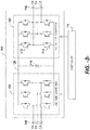
- the rotor side converter (RSC) 166 includes a plurality of bridge circuits (e.g. H-bridge circuits), with each phase of the rotor bus 156 input to the rotor side converter 166 being coupled to a single bridge circuit.
- the line side converter (LSC) 168 may also include a plurality of bridge circuits. Similar to the rotor side converter 166, the line side converter 168 also includes a single bridge circuit for each output phase of the line converter 168.
- the line side converter 168, the rotor side converter 166, or both the line side converter 168 and the rotor side converter 166 may include parallel bridge circuits without deviating from the scope of the present disclosure.
- Each bridge circuit may generally include a plurality of switching elements (e.g. IGBTs) coupled in series with one another.
- each bridge circuit includes an upper IGBT (e.g. IGBT 212) and a lower IGBT (e.g. IGBT 214).
- a diode may be coupled in parallel with each of the IGBTs.
- parallel IGBTs and diodes may be used to increase the current rating of the converter.
- the line side converter 168 and the rotor side converter 166 may be controlled, for instance, by providing control commands, using a suitable driver circuit, to the gates of the IGBTs.
- the converter controller 174 may provide suitable gate timing commands to the gates of the IGBTs of the bridge circuits.
- the control commands may control the switching frequency of the IGBTs to provide a desired output.
- the power convertor 162 may include any other suitable switching elements.
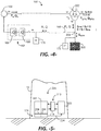
- FIG. 4 depicts real (P) and reactive (Q) power flow in a wind turbine power system 100 configured with a DFIG system 102.
- the primary source of reactive power in the DFIG system is from the RSC 166 via the generator 102 (generator stator-side reactive power (Qs)) and from the LSC 168 (generator line-side reactive power (Ql)).
- a harmonic distortion filter 175 is configured in the line side bus.
- Use of the power converter 162, in particular the RSC 166, to control the rotor current makes it is possible to adjust the total reactive power (Qwtg) of the system 100 fed to the grid from the RSC 166 independently of the rotational speed of the generator 102.
- the DFIG generator 102 is able to import or export reactive power, which allows the system to support the grid during extreme voltage fluctuations on the grid.
- the wind turbine power system 100 includes a dedicated reactive power compensation device 200 (also referred to herein as a modular VAR Box (MVB)) that generates an auxiliary reactive power (Qmvb).
- the reactive power compensation device 200 is connected to the line side bus 188 (with a different harmonic distortion filter 175) at connection point 204 such that (Qmvb) combines with (Ql) on the line side bus as (Q), wherein (Q) and (Qs) are combined at the three-way transformer 202.
- Total reactive power (Qwtg) and total real power (Pwtg) are delivered from the transformer 202 to the grid.
- the maximum reactive power capacities for (Qmvb), (Qs), and (Ql) are determined in real-time based on any one or combination of: power system operating state; ambient temperature; or thermal constraints of the generator; power converter, or reactive power compensation device.
- the values for (Qmvb), (Qs), and (Ql) may be continuously or periodically determined and updated in the control system.
- the reactive power compensation device 200 may be any one or combination of a Static VAR compensator (SVC), a Static VAR Generator (SVG) device, or a Static Synchronous Compensator (STATCOM) device.
- SVC Static VAR compensator
- SVG Static VAR Generator
- STATCOM Static Synchronous Compensator
- the reactive power compensation device 200 is connected with the line side bus 188 at the connection point 204.
- both the LSC 168 and the MVB 200 are commonly connected to the same three-way transformer 202.
- a down-tower location 226 is depicted within the wind turbine tower 12.
- the "down-tower” location is at or near the ground level within the tower 12 where the electronic control cabinets are located, including the power converter 162 and controller 174.
- a cooling system 210 (with heat exchanger 214) is configured to deliver a cooling medium (e.g. air or liquid) to the electronic components to maintain the components within an acceptable operating temperature range.
- the MVB 200 is also located at the down-tower location 226 in proximity to the power converter 162 and is also cooled by the same cooling system 210.
- the power converter controller 174 is configured with a LSC controller 206 and a RSC controller 208.
- a control line 224 connects the LSC controller 206 with the MVB 200 so that the MVB is also controlled by the LSC controller 206.
- Fig. 5 is not intended to limit location of the MVB 200, power converter 162, or cooling system. In other embodiments, these components may be located in an up-tower location closer to the nacelle.
- a total reactive power demand (Qcmd) is made on the wind turbine system 100 at a first grid state, such as a steady-state voltage on the grid.
- This (Qcmd) command may be generated, for example, by a farm-level controller in a wind farm that encompasses multiple wind turbines.
- the total (Qcmd) is allocated between generator reactive power (Qg) and compensation device reactive power (Qmvb). Referring to FIG. 4 , it is appreciated that (Qg) is the sum of (Qs) and (Ql).
- a first reactive power droop scheme is determined that includes a reactive power droop value (the same or different) applied to the control loop one or both of (Qg) and (Qmvb) at the first grid state, which may be a steady-state voltage on the grid.
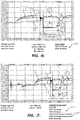
- the signal labeled "a” is total reactive power from the DFIG system 100 at the point of connection with the grid.
- the signal labeled "b” corresponds to (Qmvb) from the reactive power compensation device.
- the signal labeled "c” corresponds to (Qs).
- (Qg) is the sum of (Qs) and (Ql).
- (Qg) 1500 kVar
- (Qmvb) 1000 kVAr
- (Qs) 300kVar
- (Ql) 200kVar.
- the first reactive power droop scheme 215 applies a 5% droop value to the control loop that determines and maintains (Qg) and a 0% droop value to the control loop for (Qmvb). These values are determined to minimize reactive power oscillations between the generator and the reactive power compensation device at steady-state grid voltages.
- FIG. 6 depicts the LVRT (Low Voltage Ride Through) response of the system 100 wherein the first reactive power scheme is maintained throughout the fault and recovery. Thus, in the example of Fig. 6 , a second reactive power scheme is not utilized. As indicated in the graph of FIG. 6 , the fault recovery time for the generator to reach the pre-fault operating point takes about 3 seconds.
- FIG. 7 depicts the same grid fault, (Qg) and (Qmvb) values, and first reactive power scheme 215 (i.e., 5% droop applied to the (Qg) control loop and 0% droop applied to the (Qmvb) control loop) as in FIG. 6 .
- first reactive power scheme 215 i.e., 5% droop applied to the (Qg) control loop and 0% droop applied to the (Qmvb) control loop
- a post-fault second droop scheme 217 is implemented wherein the 5% droop applied to (Qg) in the first scheme 215 is changed to 0% during the recovery.
- the recovery time is significantly improved to approximately 2 seconds (as compared to 3 seconds in FIG. 6 ).
- the method includes changing both of the reactive power droop values applied to the (Qg) and (Qmvb) control loops in the second power scheme 217.
- the first reactive power scheme may include a 5% droop value applied to each of the (Qg) and (Qmvb) control loops, wherein this is changed to 0% applied to each of the (Qg) and (Qmvb) control loops in the second reactive power scheme.
- the second droop scheme 217 may include 0% droop applied to each of (Qg) and (Qmvb) for a predefined time period (e.g., 100msec.).
- the second droop scheme 217 may include additional droop values determined and applied independently to each of (Qg) and (Qmvb) after the initial 0% droop period.
- the second droop scheme 217 may include a plurality of different droop values applied to one or both of the (Qg) and (Qmvb) control loops according to a timed, predefined profile.
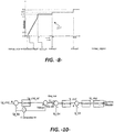
- FIG. 8 is provided as an example of a droop scheme profile that may be applied to one or both of the (Qg) and (Qmvb) control loops, wherein the profile is independently determined and stored for each of (Qg) and (Qmvb).
- Kdroop2 a second droop value
- Kdroop3 a third droop value
- Kdroop4 a fourth droop value
- Kdroop5 a fifth droop value
- a plurality of the predefined profiles used in the second reactive power scheme 217 for the (Qg) and (Qmvb) control loops may be pre-determined and stored in a look-up table, wherein a particular profile is selected as a function of type of grid fault, or any other combination of variables, such as the (Qcmd) demand made on the wind turbine system, initial values and/or capacity of (Qg) and (Qmvb), and so forth.
- FIG. 9 depicts an exemplary control method 220 of an embodiment in accordance with aspects of the present disclosure.
- the method 220 reflects the control loop process for (Qg) depicted in FIG 10 , wherein a droop value is applied in the control loop as discussed above.
- the method 220 starts at step 222.
- a reactive power command (Qcmd) for the wind turbine system is received, for example from a farm-level controller.
- a reactive power feedback signal (Qg_fbk) from the DFIG and a grid voltage feedback signal (Vg_fbk) are also generated. If grid voltage indicates a transient or fault state on the grid, then based on the grid voltage, the second reactive power droop scheme is implemented.
- (Qcmd) is allocated to (Qmvb) assigned to the reactive power compensation device and (Qg_cmd) assigned to the DFIG.
- a reactive power command (Qg_cmd) is generated for the DFIG.
- (Qmvb) is transmitted to the controller for the reactive power compensation device, wherein a parallel process of the remaining steps 230-244 indicated in FIG. 9 proceeds for determination and application of droop to be applied to the (Qmvb) control loop.
- a droop value (K_droop) is determined for (Qg_cmd) in the second reactive power droop scheme.
- This (K_droop) value may be selected from a plurality of stored profiles, as discussed above, or in an alternate embodiment, may be computed in real-time.
- an intermediate voltage command (V_cmd_int) is generated based on (Qg_cmd and Qg_fbk).
- step 234 the (K_droop) value is applied to (Q_fbk) to calculate voltage droop (Vdroop).
- a final voltage command (Vg_cmd) is calculated based on (V_cmd_int) and (Vdroop).
- a reactive current command (Iy_cmd) is generated, and at step 240 a power converter voltage command (Vy_cmd) is generated from (Iy_cmd).
- the (Vy_cmd) is used to generate a modulation index for the power converter, which is primarily responsible for generation of reactive power from the DFIG.
- step 244 It is understood, however, that the applicable steps of the method 220 will be repeated for changes in droop value for the DFIG as dictated by the stored (K_droop) profile, as discussed above.
Applications Claiming Priority (1)
| Application Number | Priority Date | Filing Date | Title |
|---|---|---|---|
| US16/403,870 US10790668B1 (en) | 2019-05-06 | 2019-05-06 | Method for reactive power oscillation damping for a wind turbine system with integrated reactive power compensation device |
Publications (2)
| Publication Number | Publication Date |
|---|---|
| EP3736938A1 true EP3736938A1 (fr) | 2020-11-11 |
| EP3736938B1 EP3736938B1 (fr) | 2022-04-06 |
Family
ID=70553925
Family Applications (1)
| Application Number | Title | Priority Date | Filing Date |
|---|---|---|---|
| EP20173034.8A Active EP3736938B1 (fr) | 2019-05-06 | 2020-05-05 | Procédé d'amortissement de l'oscillation de puissance réactive pour un système d'éolienne doté d'un dispositif de compensation de puissance réactive intégré |
Country Status (4)
| Country | Link |
|---|---|
| US (1) | US10790668B1 (fr) |
| EP (1) | EP3736938B1 (fr) |
| DK (1) | DK3736938T3 (fr) |
| ES (1) | ES2922321T3 (fr) |
Families Citing this family (4)
| Publication number | Priority date | Publication date | Assignee | Title |
|---|---|---|---|---|
| DE102017112958A1 (de) * | 2017-06-13 | 2018-12-13 | Wobben Properties Gmbh | Windenergieanlage mit getriebelosem Generator und Generatorfilter |
| CN112165125B (zh) * | 2020-10-09 | 2022-10-14 | 国电南瑞科技股份有限公司 | 一种惯量反下垂控制方法及系统 |
| EP3993215A1 (fr) * | 2020-10-29 | 2022-05-04 | Wobben Properties GmbH | Bandes frt dynamiques pour éoliennes |
| CN112769141A (zh) * | 2020-12-30 | 2021-05-07 | 西南交通大学 | 一种采用svg补偿的风电并网运行电压控制方法 |
Citations (8)
| Publication number | Priority date | Publication date | Assignee | Title |
|---|---|---|---|---|
| US20100332040A1 (en) * | 2009-06-24 | 2010-12-30 | Vestas Wind Systems A/S | Current control of a wind park |
| EP2482421A1 (fr) * | 2011-01-31 | 2012-08-01 | Sinovel Wind Group Co., Ltd | Système réactif de contrôle de la tension et procédé de parc d'éoliennes d'unités éoliennes à double alimentation |
| US20150137520A1 (en) * | 2012-06-12 | 2015-05-21 | Vestas Wind Systems A/S | Wind-power-plant control upon low-voltage grid faults |
| US20150295529A1 (en) | 2014-04-15 | 2015-10-15 | General Electric Company | Reactive power control for wind turbine generators |
| US20160322821A1 (en) * | 2013-12-11 | 2016-11-03 | Vestas Wind Systems A/S | A wind power plant, and a method for controlling a reactive current injection in a wind power plant |
| US20170025858A1 (en) | 2013-11-28 | 2017-01-26 | Vestas Wind Systems A/S | Reconfiguration of the reactive power loop of a wind power plant |
| US20170317498A1 (en) * | 2016-05-02 | 2017-11-02 | Nec Laboratories America, Inc. | Resiliency Controller for Voltage Regulation in Microgrids |
| US20190013754A1 (en) * | 2017-07-06 | 2019-01-10 | General Electric Company | Allocating Reactive Power Production for Doubly Fed Induction Generator Wind Turbine System |
Family Cites Families (35)
| Publication number | Priority date | Publication date | Assignee | Title |
|---|---|---|---|---|
| US7071579B2 (en) | 2002-06-07 | 2006-07-04 | Global Energyconcepts,Llc | Wind farm electrical system |
| US7245037B2 (en) | 2002-09-13 | 2007-07-17 | Abb Ab | Wind power fed network |
| US7095597B1 (en) | 2003-04-30 | 2006-08-22 | Clipper Windpower Technology, Inc. | Distributed static var compensation (DSVC) system for wind and water turbine applications |
| US6924565B2 (en) | 2003-08-18 | 2005-08-02 | General Electric Company | Continuous reactive power support for wind turbine generators |
| US7119452B2 (en) | 2003-09-03 | 2006-10-10 | General Electric Company | Voltage control for wind generators |
| US7013203B2 (en) | 2003-10-22 | 2006-03-14 | General Electric Company | Wind turbine system control |
| US7567160B2 (en) | 2006-02-15 | 2009-07-28 | American Superconductor Corporation | Supplementary transformer cooling in a reactive power compensation system |
| WO2011012733A1 (fr) | 2009-07-27 | 2011-02-03 | Gamesa Innovation & Technology, S.L. | Système pour la compensation d'énergie réactive dans un système d'énergie électrique |
| US7923862B2 (en) | 2009-10-06 | 2011-04-12 | General Electric Company | Reactive power regulation and voltage support for renewable energy plants |
| US9478987B2 (en) | 2009-11-10 | 2016-10-25 | Siemens Aktiengesellschaft | Power oscillation damping employing a full or partial conversion wind turbine |
| WO2011104273A2 (fr) | 2010-02-25 | 2011-09-01 | Vestas Wind Systems A/S | Procédé et dispositif de commande destinés à commander une source de puissance réactive |
| CN103004050B (zh) | 2010-06-03 | 2016-01-20 | 维斯塔斯风力系统集团公司 | 用于控制风力发电厂中的中央电容器的方法和控制装置 |
| US8664800B2 (en) | 2010-08-31 | 2014-03-04 | General Electric Company | System and method for distribution of inverter VAR support |
| EP2503146B1 (fr) | 2011-03-21 | 2013-12-18 | Siemens Aktiengesellschaft | Procédé et agencement de contrôle du fonctionnement d'une installation de production d'énergie électrique durant une déconnexion de grille utilitaire. |
| WO2012178176A1 (fr) | 2011-06-23 | 2012-12-27 | Inventus Holdings, Llc | Génération électrique à multiples sites renouvelables et commande de puissance réactive |
| WO2013160486A2 (fr) | 2012-04-27 | 2013-10-31 | Repower Systems Se | Parc éolien permettant une régulation locale rapide de la puissance réactive |
| EP2896099B1 (fr) | 2012-09-17 | 2016-11-30 | Vestas Wind Systems A/S | Procédé de détermination des points de consigne individuels dans un dispositif de commande de centrale électrique, et dispositif de commande de centrale électrique |
| EP2896102B1 (fr) | 2012-09-17 | 2017-02-22 | Vestas Wind Systems A/S | Procédé de détermination des points de consigne individuels dans un dispositif de commande de centrale électrique et dispositif de commande de centrale électrique |
| CN102882229B (zh) | 2012-09-21 | 2015-06-17 | 北京金风科创风电设备有限公司 | 风电场动态电压自动控制系统 |
| EP2741392A3 (fr) | 2012-12-04 | 2016-12-14 | ABB Research Ltd. | Systèmes et procédés permettant d'utiliser un compensateur actif pour augmenter un redresseur à diodes |
| US9680307B2 (en) | 2012-12-21 | 2017-06-13 | General Electric Company | System and method for voltage regulation of a renewable energy plant |
| EP2957012B1 (fr) | 2013-02-15 | 2017-05-03 | Vestas Wind Systems A/S | Procédé de fonctionnement d'une centrale éolienne |
| US9318988B2 (en) | 2013-09-05 | 2016-04-19 | General Electric Company | System and method for voltage control of wind generators |
| US9419439B2 (en) | 2014-01-14 | 2016-08-16 | Siemens Aktiengesellschaft | Reconnecting a wind power plant to a utility grid |
| CN103955572B (zh) | 2014-04-23 | 2018-03-20 | 国家电网公司 | 一种双馈式风力发电机组机电暂态模型的建模方法 |
| US10008854B2 (en) * | 2015-02-19 | 2018-06-26 | Enphase Energy, Inc. | Method and apparatus for time-domain droop control with integrated phasor current control |
| US9831810B2 (en) | 2015-03-10 | 2017-11-28 | General Electric Company | System and method for improved reactive power speed-of-response for a wind farm |
| US10431980B2 (en) * | 2016-01-25 | 2019-10-01 | Enphase Energy, Inc. | Method and apparatus for increased energy harvest in a microgrid |
| US10027118B2 (en) * | 2016-05-19 | 2018-07-17 | General Electric Company | System and method for balancing reactive power loading between renewable energy power systems |
| CN106451483A (zh) | 2016-08-01 | 2017-02-22 | 郭权利 | 基于双馈风电机组风电场无功补偿装置及控制方法 |
| CN106532771A (zh) | 2016-12-01 | 2017-03-22 | 国网新疆电力公司经济技术研究院 | 一种自适应电压跌落的双馈风电机组低电压穿越实现方法 |
| CN106532730B (zh) * | 2016-12-28 | 2019-01-29 | 江苏金风科技有限公司 | 微电网动态稳定控制系统和方法 |
| CN106655272B (zh) * | 2017-01-16 | 2018-12-04 | 湖南大学 | 抑制故障瞬时冲击电流型虚拟同步逆变器及其控制方法 |
| CN107171335B (zh) | 2017-06-22 | 2020-11-03 | 清华大学 | 一种基于本地无功调节的风电场电压协调控制方法 |
| CN107834564B (zh) | 2017-11-02 | 2021-04-30 | 上海电力学院 | 一种微电网系统的小干扰电压稳定性的控制方法 |
-
2019
- 2019-05-06 US US16/403,870 patent/US10790668B1/en active Active
-
2020
- 2020-05-05 ES ES20173034T patent/ES2922321T3/es active Active
- 2020-05-05 DK DK20173034.8T patent/DK3736938T3/da active
- 2020-05-05 EP EP20173034.8A patent/EP3736938B1/fr active Active
Patent Citations (8)
| Publication number | Priority date | Publication date | Assignee | Title |
|---|---|---|---|---|
| US20100332040A1 (en) * | 2009-06-24 | 2010-12-30 | Vestas Wind Systems A/S | Current control of a wind park |
| EP2482421A1 (fr) * | 2011-01-31 | 2012-08-01 | Sinovel Wind Group Co., Ltd | Système réactif de contrôle de la tension et procédé de parc d'éoliennes d'unités éoliennes à double alimentation |
| US20150137520A1 (en) * | 2012-06-12 | 2015-05-21 | Vestas Wind Systems A/S | Wind-power-plant control upon low-voltage grid faults |
| US20170025858A1 (en) | 2013-11-28 | 2017-01-26 | Vestas Wind Systems A/S | Reconfiguration of the reactive power loop of a wind power plant |
| US20160322821A1 (en) * | 2013-12-11 | 2016-11-03 | Vestas Wind Systems A/S | A wind power plant, and a method for controlling a reactive current injection in a wind power plant |
| US20150295529A1 (en) | 2014-04-15 | 2015-10-15 | General Electric Company | Reactive power control for wind turbine generators |
| US20170317498A1 (en) * | 2016-05-02 | 2017-11-02 | Nec Laboratories America, Inc. | Resiliency Controller for Voltage Regulation in Microgrids |
| US20190013754A1 (en) * | 2017-07-06 | 2019-01-10 | General Electric Company | Allocating Reactive Power Production for Doubly Fed Induction Generator Wind Turbine System |
Also Published As
| Publication number | Publication date |
|---|---|
| ES2922321T3 (es) | 2022-09-13 |
| DK3736938T3 (da) | 2022-07-11 |
| US10790668B1 (en) | 2020-09-29 |
| EP3736938B1 (fr) | 2022-04-06 |
Similar Documents
| Publication | Publication Date | Title |
|---|---|---|
| EP3736938A1 (fr) | Procédé d'amortissement de l'oscillation de puissance réactive pour un système d'éolienne doté d'un dispositif de compensation de puissance réactive intégré | |
| Xiang et al. | Coordinated control of an HVDC link and doubly fed induction generators in a large offshore wind farm | |
| US20120242295A1 (en) | Method and arrangement for controlling an operation of an electric energy production facility during a disconnection to a utility grid | |
| US10581247B1 (en) | System and method for reactive power control of wind turbines in a wind farm supported with auxiliary reactive power compensation | |
| US10742149B1 (en) | System and method for reactive power control of a wind turbine by varying switching frequency of rotor side converter | |
| US20070273155A1 (en) | Method for operating a frequency converter of a generator and wind energy turbine having a generator operated according to the method | |
| EP3736935A1 (fr) | Système d'éolienne doté d'un dispositif de compensation de puissance réactive intégré | |
| US10767630B1 (en) | System and method for operating a wind farm during low wind speeds | |
| EP3971414A1 (fr) | Commande de formation de réseau pour ressource basée sur un onduleur utilisant une impédance virtuelle | |
| EP3893383A1 (fr) | Système et procédé de contrôle de convertisseurs d'éolienne pendant le temps de maintien d'alimentation en cas d'événements de haute tension | |
| EP3736940B1 (fr) | Système et procédé pour la commande coordonnée de la puissance réactive d'un générateur et d'un dispositif de compensation de la puissance réactive dans un système d'éolienne | |
| US11196260B2 (en) | System and method for control of reactive power from a reactive power compensation device in a wind turbine system | |
| US11506173B2 (en) | System and method for providing grid-forming control for a double-fed wind turbine generator using virtual impedance | |
| CA2835303C (fr) | Systeme et methode d'optimisation de generateur a induction a double alimentation a double pont | |
| US20230246574A1 (en) | System and method for providing grid-forming control of an inverter-based resource | |
| US10958200B1 (en) | System and method for operating a wind turbine power system during low wind speeds to improve efficiency | |
| WO2024091249A1 (fr) | Système et procédé d'extension du seuil de vitesse de fonctionnement d'une ressource à base d'onduleur formant un réseau | |
| Satheeshkumar et al. | An Efficient Control Scheme for Wind Farm Using Back to Back Converter |
Legal Events
| Date | Code | Title | Description |
|---|---|---|---|
| PUAI | Public reference made under article 153(3) epc to a published international application that has entered the european phase |
Free format text: ORIGINAL CODE: 0009012 |
|
| STAA | Information on the status of an ep patent application or granted ep patent |
Free format text: STATUS: THE APPLICATION HAS BEEN PUBLISHED |
|
| AK | Designated contracting states |
Kind code of ref document: A1 Designated state(s): AL AT BE BG CH CY CZ DE DK EE ES FI FR GB GR HR HU IE IS IT LI LT LU LV MC MK MT NL NO PL PT RO RS SE SI SK SM TR |
|
| AX | Request for extension of the european patent |
Extension state: BA ME |
|
| STAA | Information on the status of an ep patent application or granted ep patent |
Free format text: STATUS: REQUEST FOR EXAMINATION WAS MADE |
|
| 17P | Request for examination filed |
Effective date: 20210511 |
|
| RBV | Designated contracting states (corrected) |
Designated state(s): AL AT BE BG CH CY CZ DE DK EE ES FI FR GB GR HR HU IE IS IT LI LT LU LV MC MK MT NL NO PL PT RO RS SE SI SK SM TR |
|
| GRAP | Despatch of communication of intention to grant a patent |
Free format text: ORIGINAL CODE: EPIDOSNIGR1 |
|
| STAA | Information on the status of an ep patent application or granted ep patent |
Free format text: STATUS: GRANT OF PATENT IS INTENDED |
|
| INTG | Intention to grant announced |
Effective date: 20211026 |
|
| GRAS | Grant fee paid |
Free format text: ORIGINAL CODE: EPIDOSNIGR3 |
|
| GRAA | (expected) grant |
Free format text: ORIGINAL CODE: 0009210 |
|
| STAA | Information on the status of an ep patent application or granted ep patent |
Free format text: STATUS: THE PATENT HAS BEEN GRANTED |
|
| AK | Designated contracting states |
Kind code of ref document: B1 Designated state(s): AL AT BE BG CH CY CZ DE DK EE ES FI FR GB GR HR HU IE IS IT LI LT LU LV MC MK MT NL NO PL PT RO RS SE SI SK SM TR |
|
| REG | Reference to a national code |
Ref country code: GB Ref legal event code: FG4D |
|
| REG | Reference to a national code |
Ref country code: CH Ref legal event code: EP |
|
| REG | Reference to a national code |
Ref country code: AT Ref legal event code: REF Ref document number: 1482293 Country of ref document: AT Kind code of ref document: T Effective date: 20220415 |
|
| REG | Reference to a national code |
Ref country code: DE Ref legal event code: R096 Ref document number: 602020002515 Country of ref document: DE |
|
| REG | Reference to a national code |
Ref country code: IE Ref legal event code: FG4D |
|
| REG | Reference to a national code |
Ref country code: DK Ref legal event code: T3 Effective date: 20220706 |
|
| REG | Reference to a national code |
Ref country code: LT Ref legal event code: MG9D |
|
| REG | Reference to a national code |
Ref country code: NL Ref legal event code: MP Effective date: 20220406 |
|
| REG | Reference to a national code |
Ref country code: ES Ref legal event code: FG2A Ref document number: 2922321 Country of ref document: ES Kind code of ref document: T3 Effective date: 20220913 |
|
| REG | Reference to a national code |
Ref country code: AT Ref legal event code: MK05 Ref document number: 1482293 Country of ref document: AT Kind code of ref document: T Effective date: 20220406 |
|
| PG25 | Lapsed in a contracting state [announced via postgrant information from national office to epo] |
Ref country code: NL Free format text: LAPSE BECAUSE OF FAILURE TO SUBMIT A TRANSLATION OF THE DESCRIPTION OR TO PAY THE FEE WITHIN THE PRESCRIBED TIME-LIMIT Effective date: 20220406 |
|
| PG25 | Lapsed in a contracting state [announced via postgrant information from national office to epo] |
Ref country code: SE Free format text: LAPSE BECAUSE OF FAILURE TO SUBMIT A TRANSLATION OF THE DESCRIPTION OR TO PAY THE FEE WITHIN THE PRESCRIBED TIME-LIMIT Effective date: 20220406 Ref country code: PT Free format text: LAPSE BECAUSE OF FAILURE TO SUBMIT A TRANSLATION OF THE DESCRIPTION OR TO PAY THE FEE WITHIN THE PRESCRIBED TIME-LIMIT Effective date: 20220808 Ref country code: NO Free format text: LAPSE BECAUSE OF FAILURE TO SUBMIT A TRANSLATION OF THE DESCRIPTION OR TO PAY THE FEE WITHIN THE PRESCRIBED TIME-LIMIT Effective date: 20220706 Ref country code: LT Free format text: LAPSE BECAUSE OF FAILURE TO SUBMIT A TRANSLATION OF THE DESCRIPTION OR TO PAY THE FEE WITHIN THE PRESCRIBED TIME-LIMIT Effective date: 20220406 Ref country code: HR Free format text: LAPSE BECAUSE OF FAILURE TO SUBMIT A TRANSLATION OF THE DESCRIPTION OR TO PAY THE FEE WITHIN THE PRESCRIBED TIME-LIMIT Effective date: 20220406 Ref country code: GR Free format text: LAPSE BECAUSE OF FAILURE TO SUBMIT A TRANSLATION OF THE DESCRIPTION OR TO PAY THE FEE WITHIN THE PRESCRIBED TIME-LIMIT Effective date: 20220707 Ref country code: FI Free format text: LAPSE BECAUSE OF FAILURE TO SUBMIT A TRANSLATION OF THE DESCRIPTION OR TO PAY THE FEE WITHIN THE PRESCRIBED TIME-LIMIT Effective date: 20220406 Ref country code: BG Free format text: LAPSE BECAUSE OF FAILURE TO SUBMIT A TRANSLATION OF THE DESCRIPTION OR TO PAY THE FEE WITHIN THE PRESCRIBED TIME-LIMIT Effective date: 20220706 Ref country code: AT Free format text: LAPSE BECAUSE OF FAILURE TO SUBMIT A TRANSLATION OF THE DESCRIPTION OR TO PAY THE FEE WITHIN THE PRESCRIBED TIME-LIMIT Effective date: 20220406 |
|
| PG25 | Lapsed in a contracting state [announced via postgrant information from national office to epo] |
Ref country code: RS Free format text: LAPSE BECAUSE OF FAILURE TO SUBMIT A TRANSLATION OF THE DESCRIPTION OR TO PAY THE FEE WITHIN THE PRESCRIBED TIME-LIMIT Effective date: 20220406 Ref country code: PL Free format text: LAPSE BECAUSE OF FAILURE TO SUBMIT A TRANSLATION OF THE DESCRIPTION OR TO PAY THE FEE WITHIN THE PRESCRIBED TIME-LIMIT Effective date: 20220406 Ref country code: LV Free format text: LAPSE BECAUSE OF FAILURE TO SUBMIT A TRANSLATION OF THE DESCRIPTION OR TO PAY THE FEE WITHIN THE PRESCRIBED TIME-LIMIT Effective date: 20220406 Ref country code: IS Free format text: LAPSE BECAUSE OF FAILURE TO SUBMIT A TRANSLATION OF THE DESCRIPTION OR TO PAY THE FEE WITHIN THE PRESCRIBED TIME-LIMIT Effective date: 20220806 |
|
| REG | Reference to a national code |
Ref country code: DE Ref legal event code: R097 Ref document number: 602020002515 Country of ref document: DE |
|
| REG | Reference to a national code |
Ref country code: BE Ref legal event code: MM Effective date: 20220531 |
|
| PG25 | Lapsed in a contracting state [announced via postgrant information from national office to epo] |
Ref country code: SM Free format text: LAPSE BECAUSE OF FAILURE TO SUBMIT A TRANSLATION OF THE DESCRIPTION OR TO PAY THE FEE WITHIN THE PRESCRIBED TIME-LIMIT Effective date: 20220406 Ref country code: SK Free format text: LAPSE BECAUSE OF FAILURE TO SUBMIT A TRANSLATION OF THE DESCRIPTION OR TO PAY THE FEE WITHIN THE PRESCRIBED TIME-LIMIT Effective date: 20220406 Ref country code: RO Free format text: LAPSE BECAUSE OF FAILURE TO SUBMIT A TRANSLATION OF THE DESCRIPTION OR TO PAY THE FEE WITHIN THE PRESCRIBED TIME-LIMIT Effective date: 20220406 Ref country code: MC Free format text: LAPSE BECAUSE OF FAILURE TO SUBMIT A TRANSLATION OF THE DESCRIPTION OR TO PAY THE FEE WITHIN THE PRESCRIBED TIME-LIMIT Effective date: 20220406 Ref country code: LU Free format text: LAPSE BECAUSE OF NON-PAYMENT OF DUE FEES Effective date: 20220505 Ref country code: EE Free format text: LAPSE BECAUSE OF FAILURE TO SUBMIT A TRANSLATION OF THE DESCRIPTION OR TO PAY THE FEE WITHIN THE PRESCRIBED TIME-LIMIT Effective date: 20220406 Ref country code: CZ Free format text: LAPSE BECAUSE OF FAILURE TO SUBMIT A TRANSLATION OF THE DESCRIPTION OR TO PAY THE FEE WITHIN THE PRESCRIBED TIME-LIMIT Effective date: 20220406 |
|
| PLBE | No opposition filed within time limit |
Free format text: ORIGINAL CODE: 0009261 |
|
| STAA | Information on the status of an ep patent application or granted ep patent |
Free format text: STATUS: NO OPPOSITION FILED WITHIN TIME LIMIT |
|
| 26N | No opposition filed |
Effective date: 20230110 |
|
| PG25 | Lapsed in a contracting state [announced via postgrant information from national office to epo] |
Ref country code: AL Free format text: LAPSE BECAUSE OF FAILURE TO SUBMIT A TRANSLATION OF THE DESCRIPTION OR TO PAY THE FEE WITHIN THE PRESCRIBED TIME-LIMIT Effective date: 20220406 |
|
| PG25 | Lapsed in a contracting state [announced via postgrant information from national office to epo] |
Ref country code: IE Free format text: LAPSE BECAUSE OF NON-PAYMENT OF DUE FEES Effective date: 20220505 Ref country code: FR Free format text: LAPSE BECAUSE OF NON-PAYMENT OF DUE FEES Effective date: 20220606 |
|
| PG25 | Lapsed in a contracting state [announced via postgrant information from national office to epo] |
Ref country code: SI Free format text: LAPSE BECAUSE OF FAILURE TO SUBMIT A TRANSLATION OF THE DESCRIPTION OR TO PAY THE FEE WITHIN THE PRESCRIBED TIME-LIMIT Effective date: 20220406 Ref country code: BE Free format text: LAPSE BECAUSE OF NON-PAYMENT OF DUE FEES Effective date: 20220531 |
|
| P01 | Opt-out of the competence of the unified patent court (upc) registered |
Effective date: 20230530 |
|
| PGFP | Annual fee paid to national office [announced via postgrant information from national office to epo] |
Ref country code: ES Payment date: 20230601 Year of fee payment: 4 Ref country code: DK Payment date: 20230419 Year of fee payment: 4 Ref country code: DE Payment date: 20230419 Year of fee payment: 4 |
|
| REG | Reference to a national code |
Ref country code: GB Ref legal event code: 732E Free format text: REGISTERED BETWEEN 20231102 AND 20231108 |
|
| REG | Reference to a national code |
Ref country code: DE Ref legal event code: R082 Ref document number: 602020002515 Country of ref document: DE Representative=s name: ZIMMERMANN & PARTNER PATENTANWAELTE MBB, DE Ref country code: DE Ref legal event code: R082 Country of ref document: DE Ref country code: DE Ref legal event code: R081 Ref document number: 602020002515 Country of ref document: DE Owner name: GENERAL ELECTRIC RENOVABLES ESPANA, S.L., ES Free format text: FORMER OWNER: GENERAL ELECTRIC COMPANY, SCHENECTADY, NY, US |
|
| REG | Reference to a national code |
Ref country code: CH Ref legal event code: PL |
|
| PG25 | Lapsed in a contracting state [announced via postgrant information from national office to epo] |
Ref country code: LI Free format text: LAPSE BECAUSE OF NON-PAYMENT OF DUE FEES Effective date: 20230531 Ref country code: IT Free format text: LAPSE BECAUSE OF FAILURE TO SUBMIT A TRANSLATION OF THE DESCRIPTION OR TO PAY THE FEE WITHIN THE PRESCRIBED TIME-LIMIT Effective date: 20220406 Ref country code: CH Free format text: LAPSE BECAUSE OF NON-PAYMENT OF DUE FEES Effective date: 20230531 |
|
| REG | Reference to a national code |
Ref country code: DE Ref legal event code: R082 Ref document number: 602020002515 Country of ref document: DE Representative=s name: ZIMMERMANN & PARTNER PATENTANWAELTE MBB, DE |
|
| PG25 | Lapsed in a contracting state [announced via postgrant information from national office to epo] |
Ref country code: MK Free format text: LAPSE BECAUSE OF FAILURE TO SUBMIT A TRANSLATION OF THE DESCRIPTION OR TO PAY THE FEE WITHIN THE PRESCRIBED TIME-LIMIT Effective date: 20220406 Ref country code: CY Free format text: LAPSE BECAUSE OF FAILURE TO SUBMIT A TRANSLATION OF THE DESCRIPTION OR TO PAY THE FEE WITHIN THE PRESCRIBED TIME-LIMIT Effective date: 20220406 |