EP3736846A1 - Active/passive automotive fuse module - Google Patents
Active/passive automotive fuse module Download PDFInfo
- Publication number
- EP3736846A1 EP3736846A1 EP20172693.2A EP20172693A EP3736846A1 EP 3736846 A1 EP3736846 A1 EP 3736846A1 EP 20172693 A EP20172693 A EP 20172693A EP 3736846 A1 EP3736846 A1 EP 3736846A1
- Authority
- EP
- European Patent Office
- Prior art keywords
- active
- fuse
- base
- projectile
- fuse module
- Prior art date
- Legal status (The legal status is an assumption and is not a legal conclusion. Google has not performed a legal analysis and makes no representation as to the accuracy of the status listed.)
- Granted
Links
Images


Classifications
-
- H—ELECTRICITY
- H01—ELECTRIC ELEMENTS
- H01H—ELECTRIC SWITCHES; RELAYS; SELECTORS; EMERGENCY PROTECTIVE DEVICES
- H01H39/00—Switching devices actuated by an explosion produced within the device and initiated by an electric current
- H01H39/006—Opening by severing a conductor
-
- H—ELECTRICITY
- H01—ELECTRIC ELEMENTS
- H01H—ELECTRIC SWITCHES; RELAYS; SELECTORS; EMERGENCY PROTECTIVE DEVICES
- H01H85/00—Protective devices in which the current flows through a part of fusible material and this current is interrupted by displacement of the fusible material when this current becomes excessive
- H01H85/02—Details
- H01H85/04—Fuses, i.e. expendable parts of the protective device, e.g. cartridges
- H01H85/05—Component parts thereof
- H01H85/055—Fusible members
- H01H85/06—Fusible members characterised by the fusible material
-
- H—ELECTRICITY
- H01—ELECTRIC ELEMENTS
- H01H—ELECTRIC SWITCHES; RELAYS; SELECTORS; EMERGENCY PROTECTIVE DEVICES
- H01H85/00—Protective devices in which the current flows through a part of fusible material and this current is interrupted by displacement of the fusible material when this current becomes excessive
- H01H85/48—Protective devices wherein the fuse is carried or held directly by the base
-
- H—ELECTRICITY
- H01—ELECTRIC ELEMENTS
- H01H—ELECTRIC SWITCHES; RELAYS; SELECTORS; EMERGENCY PROTECTIVE DEVICES
- H01H85/00—Protective devices in which the current flows through a part of fusible material and this current is interrupted by displacement of the fusible material when this current becomes excessive
- H01H85/02—Details
- H01H85/0241—Structural association of a fuse and another component or apparatus
-
- H—ELECTRICITY
- H01—ELECTRIC ELEMENTS
- H01H—ELECTRIC SWITCHES; RELAYS; SELECTORS; EMERGENCY PROTECTIVE DEVICES
- H01H85/00—Protective devices in which the current flows through a part of fusible material and this current is interrupted by displacement of the fusible material when this current becomes excessive
- H01H85/02—Details
- H01H85/20—Bases for supporting the fuse; Separate parts thereof
- H01H85/2045—Mounting means or insulating parts of the base, e.g. covers, casings
-
- H—ELECTRICITY
- H01—ELECTRIC ELEMENTS
- H01H—ELECTRIC SWITCHES; RELAYS; SELECTORS; EMERGENCY PROTECTIVE DEVICES
- H01H85/00—Protective devices in which the current flows through a part of fusible material and this current is interrupted by displacement of the fusible material when this current becomes excessive
- H01H85/02—Details
- H01H85/20—Bases for supporting the fuse; Separate parts thereof
- H01H85/205—Electric connections to contacts on the base
-
- H—ELECTRICITY
- H01—ELECTRIC ELEMENTS
- H01H—ELECTRIC SWITCHES; RELAYS; SELECTORS; EMERGENCY PROTECTIVE DEVICES
- H01H85/00—Protective devices in which the current flows through a part of fusible material and this current is interrupted by displacement of the fusible material when this current becomes excessive
- H01H85/02—Details
- H01H85/30—Means for indicating condition of fuse structurally associated with the fuse
-
- H—ELECTRICITY
- H01—ELECTRIC ELEMENTS
- H01H—ELECTRIC SWITCHES; RELAYS; SELECTORS; EMERGENCY PROTECTIVE DEVICES
- H01H85/00—Protective devices in which the current flows through a part of fusible material and this current is interrupted by displacement of the fusible material when this current becomes excessive
- H01H85/02—Details
- H01H85/38—Means for extinguishing or suppressing arc
-
- H—ELECTRICITY
- H01—ELECTRIC ELEMENTS
- H01H—ELECTRIC SWITCHES; RELAYS; SELECTORS; EMERGENCY PROTECTIVE DEVICES
- H01H85/00—Protective devices in which the current flows through a part of fusible material and this current is interrupted by displacement of the fusible material when this current becomes excessive
- H01H85/02—Details
- H01H85/20—Bases for supporting the fuse; Separate parts thereof
- H01H85/205—Electric connections to contacts on the base
- H01H2085/2055—Connections to bus bars in an installation with screw in type fuses or knife blade fuses
-
- H—ELECTRICITY
- H01—ELECTRIC ELEMENTS
- H01H—ELECTRIC SWITCHES; RELAYS; SELECTORS; EMERGENCY PROTECTIVE DEVICES
- H01H85/00—Protective devices in which the current flows through a part of fusible material and this current is interrupted by displacement of the fusible material when this current becomes excessive
- H01H85/02—Details
- H01H85/20—Bases for supporting the fuse; Separate parts thereof
- H01H2085/2075—Junction box, having holders integrated with several other holders in a particular wiring layout
- H01H2085/208—Junction box, having holders integrated with several other holders in a particular wiring layout specially adapted for vehicles
-
- H—ELECTRICITY
- H01—ELECTRIC ELEMENTS
- H01H—ELECTRIC SWITCHES; RELAYS; SELECTORS; EMERGENCY PROTECTIVE DEVICES
- H01H85/00—Protective devices in which the current flows through a part of fusible material and this current is interrupted by displacement of the fusible material when this current becomes excessive
- H01H85/0039—Means for influencing the rupture process of the fusible element
Definitions
- This disclosure relates generally to the field of circuit protection devices and relates more particularly to an active/passive automotive fuse module that includes both passive and active circuit protection elements.
- Fuses are commonly implemented in automobile electrical systems for providing overcurrent protection. Most automobile fuses are "passive" devices that include fuse elements that are configured to carry a rated amount of electrical current during normal operation. If current flowing through a fuse element exceeds the fuse element's rated current, the fuse element will melt, disintegrate, or otherwise separate, thereby arresting the current to prevent or mitigate damage to connected electrical components.
- PIs pyrotechnic interrupters
- a controller e.g., an airbag control unit, battery management system, etc.
- a controller may send an initiation signal to a PI, causing a pyrotechnic initiator within the PI to be detonated.
- a resultant increase in pressure within the PI rapidly forcibly drives a projectile through a conductor that extends through the PI. Electrical current flowing through the PI is thereby interrupted, and the projectile, which is formed of a dielectric material, provides an electrically insulating barrier between separated portions of the conductor to prevent electrical arcing therebetween.
- An exemplary embodiment of an active/passive automotive fuse module in accordance with the present disclosure may include an electrically insulating base, a fuse plate including a bus bar portion disposed on a top surface of the base above a projectile cavity formed in the base, the fuse plate further including a fusible portion electrically connected to the bus bar portion and adapted to open when an amount of current flowing through the fuse plate exceeds a current rating of the active/passive automotive fuse module, the active/passive automotive fuse module further including a pyrotechnic interrupter (PI) disposed atop the base and including a projectile positioned above the bus bar portion, the PI configured to drive the projectile through the bus bar portion upon actuation of the PI.
- PI pyrotechnic interrupter
- an active/passive automotive fuse module in accordance with the present disclosure may include an electrically insulating base, a fuse plate including a bus bar portion disposed on a top surface of the base and above a projectile cavity formed in the base, first and second fusible portions extending perpendicularly from first and second ends of the bus bar portion into respective first and second fuse cavities formed in the base on opposite side of the projectile cavity, the first and second fusible portions adapted to open when an amount of current flowing through the fuse plate exceeds a current rating of the active/passive automotive fuse module, and first and second terminal portions extending from lower termini of the first and second fusible portions, respectively, for connecting the active/passive automotive fuse module within a circuit.
- the active/passive automotive fuse module may further include a pyrotechnic interrupter (PI) disposed atop the base, the PI including a pyrotechnic initiator and a projectile positioned above the bus bar portion, wherein the pyrotechnic initiator is configured to detonate and force the projectile through the bus bar portion upon reception of an initiation signal by the PI.
- PI pyrotechnic interrupter
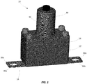
- FIGS. 1-3 a perspective view and cross-sectional views illustrating a Active/Passive automotive fuse module 10 (hereinafter “the fuse module 10") in accordance with the present disclosure is shown.
- the fuse module 10 Active/Passive automotive fuse module 10
- terms such as “front,” “rear,” “top,” “bottom,” “up,” “down,” “vertical,” and “horizontal” may be used herein to describe the relative placement and orientation of various components of the fuse module 10, each with respect to the geometry and orientation of the fuse module 10 as it appears in FIGS. 1- 3.
- Said terminology will include the words specifically mentioned, derivatives thereof, and words of similar import.
- the fuse module 10 may generally include a base 12, a fuse plate 14, a spacing cap 16, and a pyrotechnic interrupter (PI) 18.
- the base 12 may be a substantially rectangular member formed of an electrically insulating material (e.g., plastic, polymer, ceramic, etc.). As illustrated in the cross-sectional view of the fuse module 10 shown in FIG. 2 , the base 12 may include vertically-elongated first and second fuse cavities 18a, 18b formed in the top surface thereof.
- the first and second fuse cavities 18a, 18b may be substantially identical and may have lower termini (e.g., floors) located above the bottom surface of the base 12.
- the base 12 may further include a projectile cavity 20 formed in the top surface thereof, horizontally intermediate the fuse cavities 18a, 18b.
- the projectile cavity 20 may be shorter than the fuse cavities 18a, 18b.
- the present disclosure is not limited in this regard.
- the fuse plate 14 may be formed from a single piece of conductive material (e.g., stamped from a single sheet of copper) and may include a bus bar portion 22, first and second fusible portions 24a, 24b, and first and second terminal portions 26a, 26b.
- the bus bar portion 22 may be disposed on the top surface of the base 12 in a horizontal orientation and may extend from a first end disposed above the first fuse cavity 18a, over the projectile cavity 20, to a second end disposed above the second fuse cavity 18b.
- the first and second fusible portions 24a, 24b may extend perpendicularly downwardly from the first and second ends of the bus bar portion 22, respectively, into the respective first and second fuse cavities 18a, 18b.
- first and second fusible portions 24a, 24b may extend through respective slots formed in the floors of the first and second fuse cavities 18a, 18b and may be terminate below the bottom surface of the base 12.
- the first and second terminal portions 26a, 26b may extend perpendicularly outwardly (i.e., away from the projectile cavity 20) from the lower termini of the first and second fusible portions 24a, 24b, respectively, and may include respective mounting apertures 30a, 30b formed therethrough for connecting the fuse module 10 within a circuit (e.g., between a battery and one or more electrical loads in an automobile).
- the first and second fusible portions 24a, 24b may be configured to melt, disintegrate, or otherwise open if current flowing through the fuse plate 14 exceeds a predetermined threshold, or "current rating," of the fuse module 10.
- the first and second fusible portions 24a, 24b may include perforations, slots, thinned or narrowed segments, and/or various other features for making the first and second fusible portions 24a, 24b more susceptible to melting or opening than other portions of the fuse plate 14.
- the first and second fusible portions 24a, 24b may be configured to have a current rating in a range between 30 amps and 1000 amps.
- an arc-quenching, fuse filler material such as sand, silica, or the like (not shown), may partially or entirely fill the first and second fuse cavities 18a, 18b and may substantially surround the first and second fusible portions 24a, 24b for quenching electrical arcs that could otherwise propagate upon opening of the first and second fusible portions 24a, 24b during an overcurrent condition.
- the fuse module 10 may therefore be particularly well suited for high-voltage applications. While the fuse module 10 has been described and illustrated as having two fusible portions 24a, 24b, various alternative embodiments of the fuse module 10 are contemplated that may include only one fusible portion or more than two fusible portions.
- the spacing cap 16 which may be formed from an electrically insulting material that is the same as, or is similar to, that from which the base 12 is formed, may be disposed atop the base 12 and the bus bar portion 22 of the fuse plate 14.
- the spacing cap 16 may define a projectile channel 32 that extends vertically therethrough.
- the projectile channel 32 may be disposed directly above the bus bar portion 22 and the projectile cavity 20 of the base 12. While the spacing cap 16 is depicted as being separate from the base 12 it is contemplated that, in various alternative embodiments, the base 12 and the spacing cap 16 may be formed as a single, contiguous body. The present disclosure is not limited in this regard.
- the PI 18, which may be of a commercially available variety (e.g., sold under the trade name "PYROSWITCH” by AUTOLIV), may include a housing 36 having a mounting flange 38.
- the housing 36 may be disposed atop the spacing cap 16, with mechanical fasteners 40a, 40b extending through the mounting flange 38, the spacing cap 16, and the base 12 for fastening the aforementioned components together in a vertically stacked relationship as shown.
- the housing 36 may have a vertically oriented, hollow shaft 41 extending therethrough, the shaft 41 having a first, open end located directly above the projectile channel 32 of the spacing cap 16.
- the shaft 41 may contain a projectile 42 that extends into the projectile channel 32 and rests atop the bus bar portion 22 of the fuse plate 14.
- the projectile 42 may have a pointed or wedge-shaped tip disposed in a confronting relationship with the bus bar portion 22. The present disclosure is not limited in this regard.
- the housing 36 may further containin a pyrotechnic initiator 44 disposed adjacent to, and configured to discharge an explosive output into, a second, top end of the shaft 41.
- the pyrotechnic initiator 44 may be operatively connected to a controller 45 (e.g., an airbag control unit, battery management system, etc.) located within an automobile.
- the controller 45 may send an initiation signal to the PI 18, causing the pyrotechnic initiator 44 to be detonated.
- the explosive output of the detonation may result in an increase in pressure within shaft 41 rapidly forcing the projectile 42 downwardly, through the bus bar portion 22 of the fuse plate 14 as shown in FIG. 3 .
- the bus bar portion 22 is thereby severed, and electrical current flowing through the fuse plate 14 is interrupted.
- the projectile 42 which may be formed of a dielectric material, may provide an electrically insulating barrier between the separated ends of the bus bar portion 22 to prevent electrical arcing therebetween.
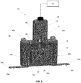
- FIG. 4 a perspective view illustrating another active/passive automotive fuse module 100 (hereinafter “the fuse module 100") in accordance with the present disclosure is shown.
- the fuse module 100 may be substantially identical to the fuse module 10 described above, with the exception of the first and second terminal portions 26a, 26b of the fuse plate 14 of the fuse module 10 being replaced by vertically extending first and second terminal prongs 126a, 126b.
- the first and second terminal prongs 126a, 126b may accommodate "plug in” applications of the fuse module 100 in which the first and second terminal prongs 126a, 126b may be mated to complementary receptacles for connecting the fuse module 100 within a circuit.
- the active/passive automotive fuse modules of the present disclosure facilitate the implementation of both passive and active circuit protection elements (e.g., conventional fuse elements and a pyrotechnic interrupter) in single, compact, space-saving form factor that facilitates convenient installation within an automobile. It will be further appreciated that the active/passive automotive fuse modules of the present disclosure may be particularly well-suited for high voltage applications.
Landscapes
- Engineering & Computer Science (AREA)
- Power Engineering (AREA)
- Fuses (AREA)
Abstract
Description
- This application claims the benefit of
U.S. Provisional Patent Application No. 62/844,358, filed May 7, 2019 - This disclosure relates generally to the field of circuit protection devices and relates more particularly to an active/passive automotive fuse module that includes both passive and active circuit protection elements.
- Fuses are commonly implemented in automobile electrical systems for providing overcurrent protection. Most automobile fuses are "passive" devices that include fuse elements that are configured to carry a rated amount of electrical current during normal operation. If current flowing through a fuse element exceeds the fuse element's rated current, the fuse element will melt, disintegrate, or otherwise separate, thereby arresting the current to prevent or mitigate damage to connected electrical components.
- In some cases, it may be desirable to "actively" create a physical opening in an electrical circuit regardless of an amount of electrical current flowing through the circuit. For example, if an automobile is involved in a collision, it may be desirable to physically open an electrical circuit in the automobile to ensure that connected electrical components are deenergized to mitigate the risk of fire and/or electrocution in the aftermath of the collision. To that end, so-called pyrotechnic interrupters (PIs) have been developed which can be selectively actuated upon the occurrence of specified events to interrupt the flow of current in a circuit. For example, in the case of an automobile collision, a controller (e.g., an airbag control unit, battery management system, etc.) may send an initiation signal to a PI, causing a pyrotechnic initiator within the PI to be detonated. A resultant increase in pressure within the PI rapidly forcibly drives a projectile through a conductor that extends through the PI. Electrical current flowing through the PI is thereby interrupted, and the projectile, which is formed of a dielectric material, provides an electrically insulating barrier between separated portions of the conductor to prevent electrical arcing therebetween.
- In certain automobile applications it may be desirable to implement both passive and active circuit protection elements. It may further be desirable to implement such elements in a compact, space-saving form factor that facilitates convenient installation and that is well suited for high voltage applications.
- It is with respect to these and other considerations that the present improvements may be useful.
- This Summary is provided to introduce a selection of concepts in a simplified form further described below in the Detailed Description. This Summary is not intended to identify key features or essential features of the claimed subject matter, nor is the summary intended as an aid in determining the scope of the claimed subject matter.
- An exemplary embodiment of an active/passive automotive fuse module in accordance with the present disclosure may include an electrically insulating base, a fuse plate including a bus bar portion disposed on a top surface of the base above a projectile cavity formed in the base, the fuse plate further including a fusible portion electrically connected to the bus bar portion and adapted to open when an amount of current flowing through the fuse plate exceeds a current rating of the active/passive automotive fuse module, the active/passive automotive fuse module further including a pyrotechnic interrupter (PI) disposed atop the base and including a projectile positioned above the bus bar portion, the PI configured to drive the projectile through the bus bar portion upon actuation of the PI.
- Another exemplary embodiment of an active/passive automotive fuse module in accordance with the present disclosure may include an electrically insulating base, a fuse plate including a bus bar portion disposed on a top surface of the base and above a projectile cavity formed in the base, first and second fusible portions extending perpendicularly from first and second ends of the bus bar portion into respective first and second fuse cavities formed in the base on opposite side of the projectile cavity, the first and second fusible portions adapted to open when an amount of current flowing through the fuse plate exceeds a current rating of the active/passive automotive fuse module, and first and second terminal portions extending from lower termini of the first and second fusible portions, respectively, for connecting the active/passive automotive fuse module within a circuit. The active/passive automotive fuse module may further include a pyrotechnic interrupter (PI) disposed atop the base, the PI including a pyrotechnic initiator and a projectile positioned above the bus bar portion, wherein the pyrotechnic initiator is configured to detonate and force the projectile through the bus bar portion upon reception of an initiation signal by the PI.
-
-
FIG. 1 is a perspective view illustrating an active/passive automotive fuse module in accordance with the present disclosure; -
FIG. 2 is a cross sectional view illustrating the active/passive automotive fuse module shown inFIG. 1 in a non-actuated state; -
FIG. 3 is a cross sectional view illustrating the active/passive automotive fuse module shown inFIG. 1 in an actuated state; -
FIG. 4 is a perspective view illustrating an active/passive automotive fuse module in accordance with the present disclosure. - An active/passive automotive fuse module in accordance with the present disclosure will now be described more fully with reference to the accompanying drawings, in which preferred embodiments of the active/passive automotive fuse module are presented. It will be understood, however, that the active/passive automotive fuse module may be embodied in many different forms and should not be construed as being limited to the embodiments set forth herein. Rather, these embodiments are provided so that this disclosure will convey certain exemplary aspects of the active/passive automotive fuse module to those skilled in the art.
- Referring to
FIGS. 1-3 , a perspective view and cross-sectional views illustrating a Active/Passive automotive fuse module 10 (hereinafter "thefuse module 10") in accordance with the present disclosure is shown. For the sake of convenience and clarity, terms such as "front," "rear," "top," "bottom," "up," "down," "vertical," and "horizontal" may be used herein to describe the relative placement and orientation of various components of thefuse module 10, each with respect to the geometry and orientation of thefuse module 10 as it appears inFIGS. 1- 3. Said terminology will include the words specifically mentioned, derivatives thereof, and words of similar import. - The
fuse module 10 may generally include abase 12, afuse plate 14, aspacing cap 16, and a pyrotechnic interrupter (PI) 18. Thebase 12 may be a substantially rectangular member formed of an electrically insulating material (e.g., plastic, polymer, ceramic, etc.). As illustrated in the cross-sectional view of thefuse module 10 shown inFIG. 2 , thebase 12 may include vertically-elongated first andsecond fuse cavities second fuse cavities base 12. Thebase 12 may further include aprojectile cavity 20 formed in the top surface thereof, horizontally intermediate thefuse cavities projectile cavity 20 may be shorter than thefuse cavities - The
fuse plate 14 may be formed from a single piece of conductive material (e.g., stamped from a single sheet of copper) and may include abus bar portion 22, first and secondfusible portions terminal portions bus bar portion 22 may be disposed on the top surface of thebase 12 in a horizontal orientation and may extend from a first end disposed above thefirst fuse cavity 18a, over theprojectile cavity 20, to a second end disposed above thesecond fuse cavity 18b. The first and secondfusible portions bus bar portion 22, respectively, into the respective first andsecond fuse cavities fusible portions second fuse cavities base 12. The first and secondterminal portions fusible portions respective mounting apertures fuse module 10 within a circuit (e.g., between a battery and one or more electrical loads in an automobile). - The first and second
fusible portions fuse plate 14 exceeds a predetermined threshold, or "current rating," of thefuse module 10. In various examples, the first and secondfusible portions fusible portions fuse plate 14. In a non-limiting example, the first and secondfusible portions second fuse cavities fusible portions fusible portions fuse module 10 may therefore be particularly well suited for high-voltage applications. While thefuse module 10 has been described and illustrated as having twofusible portions fuse module 10 are contemplated that may include only one fusible portion or more than two fusible portions. - The
spacing cap 16, which may be formed from an electrically insulting material that is the same as, or is similar to, that from which thebase 12 is formed, may be disposed atop thebase 12 and thebus bar portion 22 of thefuse plate 14. Thespacing cap 16 may define aprojectile channel 32 that extends vertically therethrough. Theprojectile channel 32 may be disposed directly above thebus bar portion 22 and theprojectile cavity 20 of thebase 12. While thespacing cap 16 is depicted as being separate from thebase 12 it is contemplated that, in various alternative embodiments, thebase 12 and thespacing cap 16 may be formed as a single, contiguous body. The present disclosure is not limited in this regard. - The
PI 18, which may be of a commercially available variety (e.g., sold under the trade name "PYROSWITCH" by AUTOLIV), may include ahousing 36 having amounting flange 38. Thehousing 36 may be disposed atop thespacing cap 16, withmechanical fasteners mounting flange 38, thespacing cap 16, and thebase 12 for fastening the aforementioned components together in a vertically stacked relationship as shown. Thehousing 36 may have a vertically oriented,hollow shaft 41 extending therethrough, theshaft 41 having a first, open end located directly above theprojectile channel 32 of thespacing cap 16. The shaft 41may contain aprojectile 42 that extends into theprojectile channel 32 and rests atop thebus bar portion 22 of thefuse plate 14. In various embodiments, theprojectile 42 may have a pointed or wedge-shaped tip disposed in a confronting relationship with thebus bar portion 22. The present disclosure is not limited in this regard. - The
housing 36 may further containin apyrotechnic initiator 44 disposed adjacent to, and configured to discharge an explosive output into, a second, top end of theshaft 41. In various embodiments, thepyrotechnic initiator 44 may be operatively connected to a controller 45 (e.g., an airbag control unit, battery management system, etc.) located within an automobile. Upon the occurrence of a specified event, such as an automobile collision, thecontroller 45 may send an initiation signal to thePI 18, causing thepyrotechnic initiator 44 to be detonated. The explosive output of the detonation may result in an increase in pressure withinshaft 41 rapidly forcing the projectile 42 downwardly, through thebus bar portion 22 of thefuse plate 14 as shown inFIG. 3 . Thebus bar portion 22 is thereby severed, and electrical current flowing through thefuse plate 14 is interrupted. The projectile 42, which may be formed of a dielectric material, may provide an electrically insulating barrier between the separated ends of thebus bar portion 22 to prevent electrical arcing therebetween. - Referring to
FIG. 4 , a perspective view illustrating another active/passive automotive fuse module 100 (hereinafter "thefuse module 100") in accordance with the present disclosure is shown. Thefuse module 100 may be substantially identical to thefuse module 10 described above, with the exception of the first and secondterminal portions fuse plate 14 of thefuse module 10 being replaced by vertically extending first and secondterminal prongs terminal prongs fuse module 100 in which the first and secondterminal prongs fuse module 100 within a circuit. - In view of the foregoing description, it will be appreciated that the active/passive automotive fuse modules of the present disclosure facilitate the implementation of both passive and active circuit protection elements (e.g., conventional fuse elements and a pyrotechnic interrupter) in single, compact, space-saving form factor that facilitates convenient installation within an automobile. It will be further appreciated that the active/passive automotive fuse modules of the present disclosure may be particularly well-suited for high voltage applications.
- As used herein, an element or step recited in the singular and proceeded with the word "a" or "an" should be understood as not excluding plural elements or steps, unless such exclusion is explicitly recited. Furthermore, references to "one embodiment" of the present disclosure are not intended to be interpreted as excluding the existence of additional embodiments that also incorporate the recited features.
- While the present disclosure makes reference to certain embodiments, numerous modifications, alterations and changes to the described embodiments are possible without departing from the sphere and scope of the present disclosure, as defined in the appended claim(s). Accordingly, it is intended that the present disclosure not be limited to the described embodiments, but that it has the full scope defined by the language of the following claims, and equivalents thereof.
Claims (15)
- An active/passive automotive fuse module comprising:an electrically insulating base;a fuse plate comprising:a bus bar portion disposed on a top surface of the base and above a projectile cavity formed in the base;a fusible portion electrically connected to the bus bar portion and adapted to open when an amount of current flowing through the fuse plate exceeds a current rating of the active/passive automotive fuse module; anda pyrotechnic interrupter (PI) disposed atop the base and including a projectile positioned above the bus bar portion, the PI configured to drive the projectile through the bus bar portion upon actuation of the PI.
- The active/passive automotive fuse module of claim 1, wherein the fusible portion is disposed within a fuse cavity in the base.
- The active/passive automotive fuse module of claim 1 or 2, wherein the fusible portion extends perpendicularly from the bus bar portion.
- The active/passive automotive fuse module of claim 2 or 3, wherein the fuse cavity is at least partially filled with an arc quenching material that surrounds the fusible portion.
- The active/passive automotive fuse module of any of the preceding claims, wherein the fusible portion is a first fusible portion extending from a first end of the bus bar portion, the fuse plate further comprising a second fusible portion extending from a second end of the bus bar portion, preferably
wherein the first fusible portion is disposed within a first fuse cavity in the base and the second fusible portion is disposed within a second fuse cavity in the base, more preferably
wherein the first and second fuse cavities are at least partially filled with an arc quenching material that surrounds the first and second fusible portions. - The active/passive automotive fuse module of any of the preceding claims, further comprising a spacing cap disposed between the base and the PI and having a projectile channel extending therethrough, wherein a portion of the projectile extends into the projectile channel.
- The active/passive automotive fuse module of any of the preceding claims, further comprising a controller operatively connected to a pyrotechnic initiator of the PI and adapted to send an actuation signal to the pyrotechnic initiator upon the occurrence of a predetermined event.
- The active/passive automotive fuse module of any of the preceding claims, wherein the fuse plate further comprises a terminal portion extending from the fusible portion, through the base, and having a mounting aperture formed therethrough for facilitating electrical connection within a circuit.
- The active/passive automotive fuse module of any of the preceding claims 1-7, wherein the fuse plate further comprises a terminal portion extending from the fusible portion, through the base, and terminating in a flat prong adapted to be plugged into a receptacle for facilitating electrical connection within a circuit.
- An active/passive automotive fuse module, optionally according to any of the preceding claims, comprising:an electrically insulating base;a fuse plate, comprising:a bus bar portion disposed on a top surface of the base and above a projectile cavity formed in the base;first and second fusible portions extending perpendicularly from first and second ends of the bus bar portion into respective first and second fuse cavities formed in the base on opposite side of the projectile cavity, the first and second fusible portions adapted to open when an amount of current flowing through the fuse plate exceeds a current rating of the active/passive automotive fuse module;first and second terminal portions extending from lower termini of the first and second fusible portions, respectively, for connecting the active/passive automotive fuse module within a circuit; anda pyrotechnic interrupter (PI) disposed atop the base, the PI including a pyrotechnic initiator and a projectile positioned above the bus bar portion, wherein the pyrotechnic initiator is configured to detonate and force the projectile through the bus bar portion upon reception of an initiation signal by the PI.
- The active/passive automotive fuse module of claim 10, wherein the first and second fuse cavities are at least partially filled with an arc quenching material that surrounds the first and second fusible portions.
- The active/passive automotive fuse module of claim 10 or 11, further comprising a spacing cap disposed between the base and the PI and having a projectile channel extending therethrough, wherein a portion of the projectile extends into the projectile channel.
- The active/passive automotive fuse module of any of the claims 10-12, further comprising a controller operatively connected to a pyrotechnic initiator of the PI and adapted to send an actuation signal to the pyrotechnic initiator upon the occurrence of a predetermined event.
- The active/passive automotive fuse module of any of the claims 10-13,
wherein each of the first and second terminal portions has a mounting aperture formed therethrough for facilitating electrical connection within a circuit, or
wherein each of the first and second terminal portions terminates in a flat prong adapted to be plugged into a receptacle for facilitating electrical connection within a circuit. - An automobile comprising an active/passive automotive fuse module according to any of the preceding claims.
Applications Claiming Priority (2)
| Application Number | Priority Date | Filing Date | Title |
|---|---|---|---|
| US201962844358P | 2019-05-07 | 2019-05-07 | |
| US16/854,111 US11355300B2 (en) | 2019-05-07 | 2020-04-21 | Active/passive automotive fuse module |
Publications (2)
| Publication Number | Publication Date |
|---|---|
| EP3736846A1 true EP3736846A1 (en) | 2020-11-11 |
| EP3736846B1 EP3736846B1 (en) | 2025-03-05 |
Family
ID=70553736
Family Applications (1)
| Application Number | Title | Priority Date | Filing Date |
|---|---|---|---|
| EP20172693.2A Active EP3736846B1 (en) | 2019-05-07 | 2020-05-04 | Active/passive automotive fuse module |
Country Status (4)
| Country | Link |
|---|---|
| US (1) | US11355300B2 (en) |
| EP (1) | EP3736846B1 (en) |
| JP (1) | JP7695033B2 (en) |
| CN (1) | CN111916321B (en) |
Cited By (2)
| Publication number | Priority date | Publication date | Assignee | Title |
|---|---|---|---|---|
| EP4307333A1 (en) * | 2022-07-14 | 2024-01-17 | Littelfuse, Inc. | Active/passive fuse module |
| EP4374408A4 (en) * | 2021-07-20 | 2024-10-16 | Littelfuse International Holding, LLC | ACTIVE/PASSIVE FUSE MODULE |
Families Citing this family (5)
| Publication number | Priority date | Publication date | Assignee | Title |
|---|---|---|---|---|
| JP7316367B2 (en) * | 2020-12-11 | 2023-07-27 | 西安中熔電気股▲ふん▼有限公司 | Multiple fracture induced fuses using a combination of mechanical cutting and fusing |
| JP7487153B2 (en) * | 2020-12-22 | 2024-05-20 | 現代自動車株式会社 | Emergency power management system for mobility and control method thereof |
| US11557451B1 (en) | 2021-12-07 | 2023-01-17 | Hamilton Sundstrand Corporation | High voltage high current fuse with arc interrupter |
| CN114446736A (en) * | 2022-01-13 | 2022-05-06 | 宁波峰梅新能源汽车科技有限公司 | Explosion fuse |
| SE545700C2 (en) * | 2022-03-04 | 2023-12-12 | Scania Cv Ab | Bus bar current interruption device and energy storage device |
Citations (3)
| Publication number | Priority date | Publication date | Assignee | Title |
|---|---|---|---|---|
| DE29913553U1 (en) * | 1999-08-03 | 1999-12-30 | Wilhelm Pudenz GmbH, 27243 Dünsen | Electrical fuse |
| GB2489101A (en) * | 2011-03-18 | 2012-09-19 | Gm Global Tech Operations Inc | Pyrotechnically actuated fuse for a motor vehicle |
| FR3051282A1 (en) * | 2016-05-16 | 2017-11-17 | Herakles | CUTTING DEVICE FOR CONNECTING TO AN ELECTRICAL CIRCUIT |
Family Cites Families (16)
| Publication number | Priority date | Publication date | Assignee | Title |
|---|---|---|---|---|
| JPS5313869Y2 (en) * | 1972-01-20 | 1978-04-13 | ||
| US6295930B1 (en) * | 1998-01-08 | 2001-10-02 | Harness System Technologies Research, Ltd. | Circuit breaker |
| US6753755B2 (en) * | 2001-06-28 | 2004-06-22 | Safer Home, Inc. | Electrical safety connector fuse |
| US20040041682A1 (en) * | 2002-08-29 | 2004-03-04 | Pasha Brian D. | Battery circuit disconnect device |
| US7123124B2 (en) * | 2003-10-17 | 2006-10-17 | Special Devices, Inc. | Pyrotechnic circuit breaker |
| JP2010244921A (en) | 2009-04-08 | 2010-10-28 | Taiheiyo Seiko Kk | High-voltage fuse |
| JP5323623B2 (en) | 2009-09-14 | 2013-10-23 | 太平洋精工株式会社 | Automotive fuse |
| CN203398063U (en) * | 2013-07-19 | 2014-01-15 | 厦门赛尔特电子有限公司 | Fuse in the shape of n |
| US10566160B2 (en) * | 2015-05-18 | 2020-02-18 | Gigavac, Llc | Passive triggering mechanisms for use with switching devices incorporating pyrotechnic features |
| JP6516155B2 (en) | 2015-06-25 | 2019-05-22 | 富士電機機器制御株式会社 | fuse |
| US10312040B2 (en) * | 2016-05-11 | 2019-06-04 | Eaton Intelligent Power Limited | Modular circuit protection systems and methods |
| DE102017203851B4 (en) * | 2016-11-28 | 2018-06-14 | Volkswagen Aktiengesellschaft | Electrical fuse, method of operating an electrical fuse and electric traction network |
| JP7033595B2 (en) * | 2016-12-05 | 2022-03-10 | リテルヒューズ・インク | Battery terminal fuse module |
| US10283307B2 (en) * | 2017-04-05 | 2019-05-07 | Littelfuse, Inc. | Surface mount fuse |
| DE102017011631B4 (en) * | 2017-12-15 | 2020-02-13 | Panasonic Industrial Devices Europe Gmbh | Device for interrupting an electrical circuit |
| US11043344B2 (en) * | 2018-05-23 | 2021-06-22 | Eaton Intelligent Power Limited | Arc flash reduction maintenance system with pyrotechnic circuit protection modules |
-
2020
- 2020-04-21 US US16/854,111 patent/US11355300B2/en active Active
- 2020-05-04 EP EP20172693.2A patent/EP3736846B1/en active Active
- 2020-05-05 JP JP2020081643A patent/JP7695033B2/en active Active
- 2020-05-07 CN CN202010384326.4A patent/CN111916321B/en active Active
Patent Citations (3)
| Publication number | Priority date | Publication date | Assignee | Title |
|---|---|---|---|---|
| DE29913553U1 (en) * | 1999-08-03 | 1999-12-30 | Wilhelm Pudenz GmbH, 27243 Dünsen | Electrical fuse |
| GB2489101A (en) * | 2011-03-18 | 2012-09-19 | Gm Global Tech Operations Inc | Pyrotechnically actuated fuse for a motor vehicle |
| FR3051282A1 (en) * | 2016-05-16 | 2017-11-17 | Herakles | CUTTING DEVICE FOR CONNECTING TO AN ELECTRICAL CIRCUIT |
Cited By (3)
| Publication number | Priority date | Publication date | Assignee | Title |
|---|---|---|---|---|
| EP4374408A4 (en) * | 2021-07-20 | 2024-10-16 | Littelfuse International Holding, LLC | ACTIVE/PASSIVE FUSE MODULE |
| EP4307333A1 (en) * | 2022-07-14 | 2024-01-17 | Littelfuse, Inc. | Active/passive fuse module |
| US12308194B2 (en) | 2022-07-14 | 2025-05-20 | Littelfuse, Inc. | Active/passive fuse module |
Also Published As
| Publication number | Publication date |
|---|---|
| US20200357594A1 (en) | 2020-11-12 |
| JP2020184541A (en) | 2020-11-12 |
| EP3736846B1 (en) | 2025-03-05 |
| JP7695033B2 (en) | 2025-06-18 |
| CN111916321B (en) | 2025-07-01 |
| US11355300B2 (en) | 2022-06-07 |
| CN111916321A (en) | 2020-11-10 |
Similar Documents
| Publication | Publication Date | Title |
|---|---|---|
| US11355300B2 (en) | Active/passive automotive fuse module | |
| US11387068B2 (en) | Active/passive fuse module | |
| EP3840006B1 (en) | Active and passive fuse module | |
| US10661656B2 (en) | Pyrotechnic switch and intermediate circuit discharge system | |
| JPH0845405A (en) | Pyro-technique high current protective element | |
| JP2002512422A (en) | Especially for the separation of electrical circuits for high current strength | |
| US11594391B2 (en) | Active/passive fuse module | |
| US20230343532A1 (en) | Pyrotechnic circuit breaker | |
| CN114586124B (en) | Switch with actuator | |
| US12308194B2 (en) | Active/passive fuse module | |
| US20210066011A1 (en) | Device for Interrupting an Electrical Current Circuit | |
| CN113994450B (en) | DC circuit interrupter switch assembly | |
| EP4374408A1 (en) | Active/passive fuse module | |
| CN108711543B (en) | Electric automobile fuse | |
| KR101939927B1 (en) | Plug | |
| CN224096679U (en) | Intelligent excitation fuse | |
| EP4184547B1 (en) | Fuse module with clamped fuse installation | |
| CN223193726U (en) | Circuit breaker components, motor controller components, powertrain and vehicles | |
| EP4195232B1 (en) | High voltage high current fuse with arc interrupter | |
| CN221642288U (en) | Circuit breaker, power battery system and electric vehicle | |
| CN220774277U (en) | Intelligent fuse with bending type connecting piece | |
| JP2001307834A (en) | Connector and wiring structure | |
| CN108475759A (en) | Battery cells for electrical accumulators | |
| JP2000090794A (en) | Circuit breaker | |
| JP2000082372A (en) | Circuit breaker |
Legal Events
| Date | Code | Title | Description |
|---|---|---|---|
| PUAI | Public reference made under article 153(3) epc to a published international application that has entered the european phase |
Free format text: ORIGINAL CODE: 0009012 |
|
| STAA | Information on the status of an ep patent application or granted ep patent |
Free format text: STATUS: THE APPLICATION HAS BEEN PUBLISHED |
|
| AK | Designated contracting states |
Kind code of ref document: A1 Designated state(s): AL AT BE BG CH CY CZ DE DK EE ES FI FR GB GR HR HU IE IS IT LI LT LU LV MC MK MT NL NO PL PT RO RS SE SI SK SM TR |
|
| AX | Request for extension of the european patent |
Extension state: BA ME |
|
| STAA | Information on the status of an ep patent application or granted ep patent |
Free format text: STATUS: REQUEST FOR EXAMINATION WAS MADE |
|
| 17P | Request for examination filed |
Effective date: 20210506 |
|
| RBV | Designated contracting states (corrected) |
Designated state(s): AL AT BE BG CH CY CZ DE DK EE ES FI FR GB GR HR HU IE IS IT LI LT LU LV MC MK MT NL NO PL PT RO RS SE SI SK SM TR |
|
| STAA | Information on the status of an ep patent application or granted ep patent |
Free format text: STATUS: EXAMINATION IS IN PROGRESS |
|
| 17Q | First examination report despatched |
Effective date: 20231031 |
|
| GRAP | Despatch of communication of intention to grant a patent |
Free format text: ORIGINAL CODE: EPIDOSNIGR1 |
|
| STAA | Information on the status of an ep patent application or granted ep patent |
Free format text: STATUS: GRANT OF PATENT IS INTENDED |
|
| INTG | Intention to grant announced |
Effective date: 20240930 |
|
| GRAS | Grant fee paid |
Free format text: ORIGINAL CODE: EPIDOSNIGR3 |
|
| GRAA | (expected) grant |
Free format text: ORIGINAL CODE: 0009210 |
|
| STAA | Information on the status of an ep patent application or granted ep patent |
Free format text: STATUS: THE PATENT HAS BEEN GRANTED |
|
| AK | Designated contracting states |
Kind code of ref document: B1 Designated state(s): AL AT BE BG CH CY CZ DE DK EE ES FI FR GB GR HR HU IE IS IT LI LT LU LV MC MK MT NL NO PL PT RO RS SE SI SK SM TR |
|
| REG | Reference to a national code |
Ref country code: GB Ref legal event code: FG4D |
|
| GRAT | Correction requested after decision to grant or after decision to maintain patent in amended form |
Free format text: ORIGINAL CODE: EPIDOSNCDEC |
|
| P01 | Opt-out of the competence of the unified patent court (upc) registered |
Free format text: CASE NUMBER: APP_5463/2025 Effective date: 20250131 |
|
| GRAM | Information related to correction after decision after decision to grant or to maintain patent in amended form deleted |
Free format text: ORIGINAL CODE: EPIDOSDCDEC |
|
| REG | Reference to a national code |
Ref country code: CH Ref legal event code: EP |
|
| REG | Reference to a national code |
Ref country code: DE Ref legal event code: R096 Ref document number: 602020047087 Country of ref document: DE |
|
| REG | Reference to a national code |
Ref country code: IE Ref legal event code: FG4D |
|
| PG25 | Lapsed in a contracting state [announced via postgrant information from national office to epo] |
Ref country code: RS Free format text: LAPSE BECAUSE OF FAILURE TO SUBMIT A TRANSLATION OF THE DESCRIPTION OR TO PAY THE FEE WITHIN THE PRESCRIBED TIME-LIMIT Effective date: 20250605 |
|
| PG25 | Lapsed in a contracting state [announced via postgrant information from national office to epo] |
Ref country code: FI Free format text: LAPSE BECAUSE OF FAILURE TO SUBMIT A TRANSLATION OF THE DESCRIPTION OR TO PAY THE FEE WITHIN THE PRESCRIBED TIME-LIMIT Effective date: 20250305 |
|
| PGFP | Annual fee paid to national office [announced via postgrant information from national office to epo] |
Ref country code: DE Payment date: 20250514 Year of fee payment: 6 |
|
| REG | Reference to a national code |
Ref country code: NL Ref legal event code: MP Effective date: 20250305 |
|
| PG25 | Lapsed in a contracting state [announced via postgrant information from national office to epo] |
Ref country code: ES Free format text: LAPSE BECAUSE OF FAILURE TO SUBMIT A TRANSLATION OF THE DESCRIPTION OR TO PAY THE FEE WITHIN THE PRESCRIBED TIME-LIMIT Effective date: 20250305 |
|
| REG | Reference to a national code |
Ref country code: LT Ref legal event code: MG9D |
|
| PG25 | Lapsed in a contracting state [announced via postgrant information from national office to epo] |
Ref country code: NO Free format text: LAPSE BECAUSE OF FAILURE TO SUBMIT A TRANSLATION OF THE DESCRIPTION OR TO PAY THE FEE WITHIN THE PRESCRIBED TIME-LIMIT Effective date: 20250605 |
|
| PGFP | Annual fee paid to national office [announced via postgrant information from national office to epo] |
Ref country code: IT Payment date: 20250522 Year of fee payment: 6 |
|
| PG25 | Lapsed in a contracting state [announced via postgrant information from national office to epo] |
Ref country code: HR Free format text: LAPSE BECAUSE OF FAILURE TO SUBMIT A TRANSLATION OF THE DESCRIPTION OR TO PAY THE FEE WITHIN THE PRESCRIBED TIME-LIMIT Effective date: 20250305 |
|
| PG25 | Lapsed in a contracting state [announced via postgrant information from national office to epo] |
Ref country code: LV Free format text: LAPSE BECAUSE OF FAILURE TO SUBMIT A TRANSLATION OF THE DESCRIPTION OR TO PAY THE FEE WITHIN THE PRESCRIBED TIME-LIMIT Effective date: 20250305 |
|
| PG25 | Lapsed in a contracting state [announced via postgrant information from national office to epo] |
Ref country code: GR Free format text: LAPSE BECAUSE OF FAILURE TO SUBMIT A TRANSLATION OF THE DESCRIPTION OR TO PAY THE FEE WITHIN THE PRESCRIBED TIME-LIMIT Effective date: 20250606 Ref country code: BG Free format text: LAPSE BECAUSE OF FAILURE TO SUBMIT A TRANSLATION OF THE DESCRIPTION OR TO PAY THE FEE WITHIN THE PRESCRIBED TIME-LIMIT Effective date: 20250305 |
|
| REG | Reference to a national code |
Ref country code: AT Ref legal event code: MK05 Ref document number: 1773753 Country of ref document: AT Kind code of ref document: T Effective date: 20250305 |
|
| PG25 | Lapsed in a contracting state [announced via postgrant information from national office to epo] |
Ref country code: NL Free format text: LAPSE BECAUSE OF FAILURE TO SUBMIT A TRANSLATION OF THE DESCRIPTION OR TO PAY THE FEE WITHIN THE PRESCRIBED TIME-LIMIT Effective date: 20250305 |
|
| PG25 | Lapsed in a contracting state [announced via postgrant information from national office to epo] |
Ref country code: SE Free format text: LAPSE BECAUSE OF FAILURE TO SUBMIT A TRANSLATION OF THE DESCRIPTION OR TO PAY THE FEE WITHIN THE PRESCRIBED TIME-LIMIT Effective date: 20250305 |
|
| PG25 | Lapsed in a contracting state [announced via postgrant information from national office to epo] |
Ref country code: SM Free format text: LAPSE BECAUSE OF FAILURE TO SUBMIT A TRANSLATION OF THE DESCRIPTION OR TO PAY THE FEE WITHIN THE PRESCRIBED TIME-LIMIT Effective date: 20250305 |
|
| PG25 | Lapsed in a contracting state [announced via postgrant information from national office to epo] |
Ref country code: PT Free format text: LAPSE BECAUSE OF FAILURE TO SUBMIT A TRANSLATION OF THE DESCRIPTION OR TO PAY THE FEE WITHIN THE PRESCRIBED TIME-LIMIT Effective date: 20250707 |
|
| PG25 | Lapsed in a contracting state [announced via postgrant information from national office to epo] |
Ref country code: PL Free format text: LAPSE BECAUSE OF FAILURE TO SUBMIT A TRANSLATION OF THE DESCRIPTION OR TO PAY THE FEE WITHIN THE PRESCRIBED TIME-LIMIT Effective date: 20250305 |
|
| PG25 | Lapsed in a contracting state [announced via postgrant information from national office to epo] |
Ref country code: AT Free format text: LAPSE BECAUSE OF FAILURE TO SUBMIT A TRANSLATION OF THE DESCRIPTION OR TO PAY THE FEE WITHIN THE PRESCRIBED TIME-LIMIT Effective date: 20250305 |
|
| PG25 | Lapsed in a contracting state [announced via postgrant information from national office to epo] |
Ref country code: EE Free format text: LAPSE BECAUSE OF FAILURE TO SUBMIT A TRANSLATION OF THE DESCRIPTION OR TO PAY THE FEE WITHIN THE PRESCRIBED TIME-LIMIT Effective date: 20250305 Ref country code: CZ Free format text: LAPSE BECAUSE OF FAILURE TO SUBMIT A TRANSLATION OF THE DESCRIPTION OR TO PAY THE FEE WITHIN THE PRESCRIBED TIME-LIMIT Effective date: 20250305 |
|
| PG25 | Lapsed in a contracting state [announced via postgrant information from national office to epo] |
Ref country code: RO Free format text: LAPSE BECAUSE OF FAILURE TO SUBMIT A TRANSLATION OF THE DESCRIPTION OR TO PAY THE FEE WITHIN THE PRESCRIBED TIME-LIMIT Effective date: 20250305 |
|
| PG25 | Lapsed in a contracting state [announced via postgrant information from national office to epo] |
Ref country code: SK Free format text: LAPSE BECAUSE OF FAILURE TO SUBMIT A TRANSLATION OF THE DESCRIPTION OR TO PAY THE FEE WITHIN THE PRESCRIBED TIME-LIMIT Effective date: 20250305 |
|
| PG25 | Lapsed in a contracting state [announced via postgrant information from national office to epo] |
Ref country code: IS Free format text: LAPSE BECAUSE OF FAILURE TO SUBMIT A TRANSLATION OF THE DESCRIPTION OR TO PAY THE FEE WITHIN THE PRESCRIBED TIME-LIMIT Effective date: 20250705 |
|
| REG | Reference to a national code |
Ref country code: DE Ref legal event code: R097 Ref document number: 602020047087 Country of ref document: DE |
|
| REG | Reference to a national code |
Ref country code: CH Ref legal event code: H13 Free format text: ST27 STATUS EVENT CODE: U-0-0-H10-H13 (AS PROVIDED BY THE NATIONAL OFFICE) Effective date: 20251223 |
|
| PLBE | No opposition filed within time limit |
Free format text: ORIGINAL CODE: 0009261 |
|
| STAA | Information on the status of an ep patent application or granted ep patent |
Free format text: STATUS: NO OPPOSITION FILED WITHIN TIME LIMIT |
|
| PG25 | Lapsed in a contracting state [announced via postgrant information from national office to epo] |
Ref country code: DK Free format text: LAPSE BECAUSE OF FAILURE TO SUBMIT A TRANSLATION OF THE DESCRIPTION OR TO PAY THE FEE WITHIN THE PRESCRIBED TIME-LIMIT Effective date: 20250305 |
|
| REG | Reference to a national code |
Ref country code: CH Ref legal event code: L10 Free format text: ST27 STATUS EVENT CODE: U-0-0-L10-L00 (AS PROVIDED BY THE NATIONAL OFFICE) Effective date: 20260114 |
|
| PG25 | Lapsed in a contracting state [announced via postgrant information from national office to epo] |
Ref country code: LU Free format text: LAPSE BECAUSE OF NON-PAYMENT OF DUE FEES Effective date: 20250504 |
|
| PG25 | Lapsed in a contracting state [announced via postgrant information from national office to epo] |
Ref country code: CH Free format text: LAPSE BECAUSE OF NON-PAYMENT OF DUE FEES Effective date: 20250531 |
|
| REG | Reference to a national code |
Ref country code: BE Ref legal event code: MM Effective date: 20250531 |
|
| PG25 | Lapsed in a contracting state [announced via postgrant information from national office to epo] |
Ref country code: MC Free format text: LAPSE BECAUSE OF FAILURE TO SUBMIT A TRANSLATION OF THE DESCRIPTION OR TO PAY THE FEE WITHIN THE PRESCRIBED TIME-LIMIT Effective date: 20250305 |
|
| 26N | No opposition filed |
Effective date: 20251208 |
|
| GBPC | Gb: european patent ceased through non-payment of renewal fee |
Effective date: 20250605 |
|
| PG25 | Lapsed in a contracting state [announced via postgrant information from national office to epo] |
Ref country code: GB Free format text: LAPSE BECAUSE OF NON-PAYMENT OF DUE FEES Effective date: 20250605 |
|
| PG25 | Lapsed in a contracting state [announced via postgrant information from national office to epo] |
Ref country code: IE Free format text: LAPSE BECAUSE OF NON-PAYMENT OF DUE FEES Effective date: 20250504 |
|
| PG25 | Lapsed in a contracting state [announced via postgrant information from national office to epo] |
Ref country code: BE Free format text: LAPSE BECAUSE OF NON-PAYMENT OF DUE FEES Effective date: 20250531 |
|
| PGFP | Annual fee paid to national office [announced via postgrant information from national office to epo] |
Ref country code: FR Payment date: 20260309 Year of fee payment: 7 |