EP3736647A1 - Dependencies between process objects - Google Patents
Dependencies between process objects Download PDFInfo
- Publication number
- EP3736647A1 EP3736647A1 EP19173091.0A EP19173091A EP3736647A1 EP 3736647 A1 EP3736647 A1 EP 3736647A1 EP 19173091 A EP19173091 A EP 19173091A EP 3736647 A1 EP3736647 A1 EP 3736647A1
- Authority
- EP
- European Patent Office
- Prior art keywords
- operator station
- objects
- process object
- station server
- assigned
- Prior art date
- Legal status (The legal status is an assumption and is not a legal conclusion. Google has not performed a legal analysis and makes no representation as to the accuracy of the status listed.)
- Withdrawn
Links
Images


Classifications
-
- G—PHYSICS
- G05—CONTROLLING; REGULATING
- G05B—CONTROL OR REGULATING SYSTEMS IN GENERAL; FUNCTIONAL ELEMENTS OF SUCH SYSTEMS; MONITORING OR TESTING ARRANGEMENTS FOR SUCH SYSTEMS OR ELEMENTS
- G05B19/00—Programme-control systems
- G05B19/02—Programme-control systems electric
- G05B19/04—Programme control other than numerical control, i.e. in sequence controllers or logic controllers
- G05B19/042—Programme control other than numerical control, i.e. in sequence controllers or logic controllers using digital processors
-
- G—PHYSICS
- G05—CONTROLLING; REGULATING
- G05B—CONTROL OR REGULATING SYSTEMS IN GENERAL; FUNCTIONAL ELEMENTS OF SUCH SYSTEMS; MONITORING OR TESTING ARRANGEMENTS FOR SUCH SYSTEMS OR ELEMENTS
- G05B19/00—Programme-control systems
- G05B19/02—Programme-control systems electric
- G05B19/418—Total factory control, i.e. centrally controlling a plurality of machines, e.g. direct or distributed numerical control [DNC], flexible manufacturing systems [FMS], integrated manufacturing systems [IMS], computer integrated manufacturing [CIM]
- G05B19/4183—Total factory control, i.e. centrally controlling a plurality of machines, e.g. direct or distributed numerical control [DNC], flexible manufacturing systems [FMS], integrated manufacturing systems [IMS], computer integrated manufacturing [CIM] characterised by data acquisition, e.g. workpiece identification
-
- G—PHYSICS
- G05—CONTROLLING; REGULATING
- G05B—CONTROL OR REGULATING SYSTEMS IN GENERAL; FUNCTIONAL ELEMENTS OF SUCH SYSTEMS; MONITORING OR TESTING ARRANGEMENTS FOR SUCH SYSTEMS OR ELEMENTS
- G05B2219/00—Program-control systems
- G05B2219/30—Nc systems
- G05B2219/31—From computer integrated manufacturing till monitoring
- G05B2219/31472—Graphical display of process
Definitions
- the invention relates to an operator station server of a control system of a process engineering plant with the features of claim 1.
- the invention also relates to a control system for a process engineering plant according to claim 7.
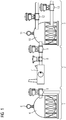
- FIG 1 a simplified excerpt of a process engineering system for the storage and distribution of gas is shown.
- the system is divided into three subsystems 1, 2, 3.
- the first subsystem 1 has a first pressure chamber 4 and a first drain valve 5 connected to it.
- the first pressure chamber 4 has a first pressure sensor 6.
- the second subsystem comprises a compressor 7, which is connected to an inlet valve 9 via a first flow sensor 8.
- the third subsystem 3 has a second pressure chamber 10 connected to the inlet valve 9.
- the second pressure chamber 10 has a second pressure sensor 11 and is connected to a second discharge valve 12 and a third discharge valve 13.
- All the technical objects 4-13 of the system shown are automated by various process objects of a control system that controls the system.
- the compressor 7 can be assigned a process object “engine control”, the inlet valve 9 a process object “inlet valve control” etc.
- the technical objects 4-6 of the first subsystem 1 as well as the technical objects 7-13 of the second and third subsystem 2, 3 are each located on a "procedural line", i.e. they are directly dependent on one another or have operative connections with one another.
- the invention is based on the object of specifying a device for operating and monitoring a process plant that makes it faster and more efficient to find alarm causes and alarm dependencies between different process objects of a process plant - without the need for additional analysis tools such as message sequence displays.
- An operator station server according to the invention of a control system of a process engineering plant has a computer-implemented process image, the computer-implemented process image at a runtime of the process engineering system including at least a first computer-implemented process object and a second computer-implemented process object, each of which is assigned to a technical object of the process engineering system and with are in operative connection with this, the two assigned technical objects being in operative connection within the process-engineering plant.
- the operator station server is characterized in that the first process object has a reference to the second process object.
- the process engineering plant can be a plant from the process industry such as a chemical, pharmaceutical, petrochemical or a plant from the food and beverage industry.
- control system each have a control system or at least one computer-aided module for controlling and regulating the ongoing process or production.
- a control system is understood to be a computer-aided technical system that includes functionalities for displaying, operating and managing a technical system such as a production facility.
- the control system includes sensors for determining measured values and various actuators.
- the control system includes so-called process or production-related components that are used to control the actuators or sensors.
- the control system shows, among other things Means for visualizing the technical system and for engineering.
- control system also includes further processing units for more complex regulations and systems for data storage and processing.
- a technical object can be individual sensors or actuators of the process engineering system.
- a technical object can also be a combination of several sensors and / or actuators, for example a motor, a reactor, a pump or a valve system.
- an "operator station server” is understood to mean a server that centrally records data from an operator control and monitoring system and, as a rule, alarm and measured value archives of a process control system of a process plant and makes it available to users.
- the operator station server usually establishes a communication link to the automation systems of the process plant and forwards data from the process plant to so-called operator station clients, which are used to operate and monitor the operation of the individual functional elements of the process plant.
- operator station server can, without being limited to this, be a SIMATIC PCS 7 industrial workstation server from SIEMENS.
- the operator station server has a process image, i.e. A current status of the technical objects of the process engineering plant is stored on the server at the runtime of the plant.
- the process image comprises at least a first computer-implemented process object and a second computer-implemented process object.
- the (first and second) process objects in the process image of the operator station server references are expanded in order to be able to relationally relate the different process objects of the process engineering system to a mapping of a process engineering line of the system.
- the reference is a structured and direction-oriented reference to another process object.
- the values of the structured reference can be derived in an engineering phase, for example from CFC plans (Continuous Functional Chart) or tabular relation matrices and integrated into the configuration of the operator station server.
- the operator station server is able to dynamically determine information on procedural strands between the individual process objects during a runtime of the procedural plant and to forward it to any downstream device for operating and monitoring.
- the operative connection between a first and a second tank can consist, for example, in the fact that a fluid can flow from the first tank into the second tank.
- the first process object preferably has further references to further process objects
- the process objects are each assigned to a technical object of the process-engineering system and are in operative connection with it, and wherein the technical objects assigned to the further process objects are in operative connection with the technical object assigned to the first process object, and the first process object is assigned information about how many references to the further process objects the first process object has.
- the operator station server can be connected to an operator station client, the operator station client being provided and designed to receive visualization information from the operator station server during a runtime of the process plant in order to at least the first and the second process object and the operative connection between the two technical objects assigned to the first and second process object in the form of symbolic system images.
- the operator station server is thus able to determine the dependency from the process objects of the symbols present in a plant picture - so to speak, to derive the process-related strand.
- the operator station server e has an operator station client, the operator station client being provided and designed to receive visualization information from the operator station server during the runtime of the process engineering system in order to at least the first and the second process object and the To visually represent active connection between the two technical objects assigned to the first and second process object in the form of symbolic system images, and the operator station client is provided and designed to provide at least one first visual representation during the runtime of the technical system, the at least one to the comprises a symbolic system image belonging to the first process object, and to generate a second visual representation which comprises at least one symbolic system image belonging to the second process object, wherein the first visual representation has a representation reference to the second visual representation, and vice versa, wherein an operator of the process engineering system can switch between a display of the two visual representations by selecting the respective representation reference.
- An operator is understood to be a human operator of the process engineering plant.
- the operator interacts with the technical system or its control system by means of special user interfaces and controls special technical functions of the system.
- the operator can use an operating and monitoring system of the control system.
- the operator can navigate along the derived procedural strand from plant picture to plant picture, for example to be able to identify the cause of a surge of alarms or the like quickly and efficiently.
- control system means that the control system, or more precisely a visualization service of the control system, is aware of information about the respective data structure types in order to be able to transfer this to a connected operator station client for graphical presentation.
- control system for a process engineering system which has at least one operator station server as explained above.
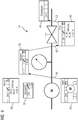
- FIG 2 a part of a control system 14 according to the invention of a technical system designed as a process engineering system is shown.
- the control system 14 comprises a first server of an operating system or an operator station server 15 and a second operator station server 16.
- the control system has an operator station client 17.
- the first operator station server 15, the second operator station server 16 and the operator station client 17 are connected to one another via a terminal bus 18 and to other components of the control system 14, not shown, such as an engineering system server or a process data archive.
- a user or operator has access to the first operator station server 15 and to the second operator station server 16 by means of the terminal bus 18 by means of the operator station client 17 in the context of operation and monitoring.
- the terminal bus 18 can, without being limited to it, be designed for example as Industrial Ethernet.
- the first operator station server 15 has a first device interface 19 which can be connected to a system bus (not shown).
- the first operator station server 15 can use this to communicate with an (external) device or an application, in particular a web application.
- the second operator station server 16 has a second device interface 20, which can also be connected to a system bus (not shown).
- the first operator station server 15 has a first computer-implemented process image 21 in which process values received at a runtime of the process engineering system are stored.
- the first operator station server 15 also includes a visualization service 23 for outputting visualization information to the operator station client 17.
- the process values are assigned to different computer-implemented process objects 22a, 22b, 22c.
- the computer-implemented process objects 22a, 22b, 22c are each assigned to a technical object of the process engineering system and are accordingly in an operative connection with them. This means that, for example, sensor values that arise in the associated technical object are mapped in the associated process object 22a, 22b, 22c.
- the process objects 22a, 22b, 22c are in FIG 2 with the designations "POI: Mot1", “POI: MonAn1" and "POI: PID1".
- Each process object 22a, 22b, 22c has a number of assigned parameters which are shown in FIG 2 are designated with "AlarmStatus", “PV_Out”, "SP_Out” etc.
- the visualization service 23 generates (among other things) a symbolic plant image 27 from the information stored in the process image 21, which is transmitted to the operator station client 17 for visualization.
- a first software component 26 of the visualization service 23 uses the references 24a, 24b, 24c to determine a dependency on block symbols generated from the process objects 22a, 22b, 22c in the symbolic system image 27 - in order to derive the procedural strand for the system image, so to speak.
- a second software component 28 of the visualization service 23 (a so-called “Screen Object Model” or SOM for short) is used to generate the block symbols for the process objects 22a, 22b, 22c for display in the system image 27.
- the first software component 26 calculates the entire procedural strand, i.e. Process objects 22a, 22b, 22c are also included in the calculation of the line, of which no block symbols are displayed in the currently displayed system image 27. If the procedural line contains process objects 22a, 22b, 22c whose block symbols are not present in the current system image 27, the system images 27 are determined for those process objects 22a, 22b, 22c in which they are present.
- group alarms are calculated and updated for the process objects 22a, 22b, 22c concerned (that is, their block symbols are shown in the respective system image 27).
- "screen change buttons” can then be dynamically created in the currently open system image 27 at runtime in order to be able to navigate along the derived procedural strand from system image 27 to system image 27. In the FIG 3-7 this aspect is illustrated even more clearly.
- the second operator station server 16 analogously to the first operator station server 15, has a second computer-implemented process image 30 in which process values received during a runtime of the process engineering system are stored.
- the second operator station server 16 also includes a visualization service 29 for outputting visualization information to the operator station client 17.
- the process values are assigned to various computer-implemented process objects 31a, 31b, 31c.
- the computer-implemented process objects 31a, 31b, 31c are each assigned to a technical object of the process engineering system and are accordingly in an operative connection with them.
- the process objects 31a, 31b, 31c are in FIG 2 with the designations "POI: MonAn2", “POI: PID2" and "POI: PID3".
- Each process object 31a, 31b, 31c has a number of assigned parameters which are shown in FIG 2 are designated with "AlarmStatus", "PV_Out", "SP_Out” etc.
- Each process object 31a, 31b, 31c has a structured and direction-oriented reference 32a, 32b, 32c, which is shown in FIG FIG 2 is designated with "Dependency Tag Struct" (the dependency is marked with double arrows 33a, 33b, 24c).
- the references 24a, 24b, 24c, 32a, 32b, 32c can also refer to process objects 22a, 22b, 22c, 31a, 31b, 31c that are in a process image 21, 30 of another operator station server 15, 16 are stored.
- the visualization service 29 of the second operator station server 16 has a first software component 34 and a second software component 35.
- FIG. 3 is an exemplary system image 27 of the first subsystem 1 and the second subsystem 2 FIG 1 with block symbols 36-40, which refer to the technical objects of the first subsystem 1 and the second subsystem 2 FIG 1 Respectively.
- a first block symbol 36 corresponds to the first discharge valve 5
- a second block symbol 37 corresponds to the first pressure sensor 6
- a third block symbol 38 corresponds to the flow sensor 8
- a fourth block symbol 39 corresponds to the compressor 7
- a fifth block symbol 40 corresponds to the Inlet valve 9.
- M the compressor 7
- the flow sensor 8 (“arrow")
- valve inlet valve 9
- the dependency determined by the first software component 26 ("DCS Domain Logic") between the technical objects on which the block symbols 36-40 are based was used dynamically by means of the second software component 27 of the first operator station server 15 to expand the system image 27 by means of the to identify the procedural line on which the selected block symbol is based.
- the procedural data flow was visualized by directed arrows 41, 42, 43 - the color of the arrow (not visible here) corresponds to the alarm class color of the highest-priority alarm along the procedural strand. Since the procedural line is located in a further plant diagram 45 (cf. FIG 5 and 6) continued, a display reference 44 (a so-called “picture change button”, labeled “subsystem 3”) was also inserted.
- the display reference 44 contains a list of the alarms of the process objects whose block symbols 46, 47, 48 are located in the further system image 45.
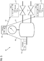
- FIG 5 is an exemplary further system image 45 of the third subsystem 3 from FIG 1 with block symbols 46, 47, 48, which relate to the technical objects of the third subsystem 3 FIG 1 Respectively.
- a first block symbol 46 corresponds to the second pressure sensor 11
- a second block symbol 47 corresponds to the second discharge valve 12
- a third block symbol 48 corresponds to the third discharge valve 13.
- FIG 5 Analogous to FIG 4 is also in FIG 5 the previously determined procedural data flow by directional arrows 49, 50, 51 visualized.
- the system image shows 45 FIG 5 a display reference 52 (“subsystem 2”), which enables a change to the system image 27, and a listing of the alarms of the process objects whose block symbols 38-40 are in the system image 27 according to FIG 4 are located.
- the operator can also directly select the alarm status in the representation references 44, 52.
- the operator can also deactivate the representation of the procedural strand in the system images 27, 45.
Abstract
Operator Station Server (15, 16) eines Leitsystems (14) einer verfahrenstechnischen Anlage, der ein computerimplementiertes Prozessabbild (21, 30) aufweist, wobei das computerimplementierte Prozessabbild (21, 30) zu einer Laufzeit der verfahrenstechnischen Anlage wenigstens ein erstes computerimplementiertes Prozessobjekt (22a, 22b, 22c, 31a, 31b, 31c) und ein zweites computerimplementiertes Prozessobjekt (22a, 22b, 22c, 31a, 31b, 31c) umfasst, die jeweils einem technischen Objekt (4, 5, 6, 7, 8, 9, 10, 11, 12, 13) der verfahrenstechnischen Anlage zugeordnet sind und mit diesem in Wirkverbindung stehen, wobei die beiden zugeordneten technischen Objekte (4, 5, 6, 7, 8, 9, 10, 11, 12, 13) in einer Wirkverbindung innerhalb der verfahrenstechnischen Anlage stehen. Der Operator Station Server (15, 16) ist dadurch gekennzeichnet, dass das erste Prozessobjekt (22a, 22b, 22c, 31a, 31b, 31c) eine Referenz (24a, 24b, 24c, 32a, 32b, 32c) auf das zweite Prozessobjekt (22a, 22b, 22c, 31a, 31b, 31c) aufweist.Operator station server (15, 16) of a control system (14) of a process engineering plant, which has a computer-implemented process image (21, 30), the computer-implemented process image (21, 30) at least one first computer-implemented process object (22a , 22b, 22c, 31a, 31b, 31c) and a second computer-implemented process object (22a, 22b, 22c, 31a, 31b, 31c) that each have a technical object (4, 5, 6, 7, 8, 9, 10 , 11, 12, 13) are assigned to the process engineering system and are in operative connection with it, the two assigned technical objects (4, 5, 6, 7, 8, 9, 10, 11, 12, 13) in operative connection within the process plant. The operator station server (15, 16) is characterized in that the first process object (22a, 22b, 22c, 31a, 31b, 31c) has a reference (24a, 24b, 24c, 32a, 32b, 32c) to the second process object ( 22a, 22b, 22c, 31a, 31b, 31c).
Description
Die Erfindung betrifft einen Operator Station Server eines Leitsystems einer verfahrenstechnischen Anlage mit den Merkmalen des Anspruchs 1. Außerdem betrifft die Erfindung ein Leitsystem für eine verfahrenstechnische Anlage gemäß Anspruch 7.The invention relates to an operator station server of a control system of a process engineering plant with the features of claim 1. The invention also relates to a control system for a process engineering plant according to
In
Alle dargestellten technischen Objekte 4-13 der Anlage werden durch verschiedene Prozessobjekte eines die Anlage steuernden Leitsystems automatisiert. Dem Kompressor 7 kann beispielsweise ein Prozessobjekt "Motorsteuerung", dem Einlassventil 9 ein Prozessobjekt "Einlassventilregelung" usw.All the technical objects 4-13 of the system shown are automated by various process objects of a control system that controls the system. For example, the
Die dargestellten technischen Objekte 4-6 der ersten Teilanlage 1 sowie die technischen Objekte 7-13 der zweiten und dritten Teilanlage 2, 3 befinden sich jeweils an einem "verfahrenstechnischen Strang", d.h. sie stehen in unmittelbarer Abhängigkeit zueinander bzw. weisen Wirkverbindungen miteinander auf.The technical objects 4-6 of the first subsystem 1 as well as the technical objects 7-13 of the second and
Die verfahrenstechnische Abhängigkeit steht in direktem Zusammenhang mit dem Alarmmanagement zwischen den Prozessobjekten - durch einen Fehler im Kompressor reduziert sich der Durchfluss, es kommt zu einem Druckabfall, usw. Für die Bedienung und Beobachtung verfahrenstechnischer Anlagen werden symbolische Anlagenbilder erstellt, die die verfahrenstechnischen Zusammenhänge abstrahiert darstellen. Aufgrund ihrer Komplexität müssen Anlagenbilder oftmals stark vereinfacht werden, so dass der verfahrenstechnische Zusammenhang oftmals verloren geht, was die Evaluierung eines Alarmschwallverursachers erschwert.The procedural dependency is directly related to the alarm management between the process objects - a fault in the compressor reduces the flow rate, there is a pressure drop, etc. For the operation and monitoring of process engineering systems, symbolic system images are created that represent the process engineering relationships in an abstract manner. Due to their complexity, plant diagrams often have to be greatly simplified, so that the procedural context is often lost, which makes it difficult to evaluate the cause of an alarm surge.
Der Erfindung liegt die Aufgabe zugrunde, eine Vorrichtung zum Bedienen und Beobachten einer verfahrenstechnischen Anlage anzugeben, die ein Auffinden von Alarmursachen und Alarmabhängigkeiten zwischen verschiedenen Prozessobjekten einer verfahrenstechnischen Anlage schneller und effizient gestaltet - ohne dass dabei zusätzliche Analysewerkzeuge wie beispielweise Meldefolgeanzeigen benötigt werden.The invention is based on the object of specifying a device for operating and monitoring a process plant that makes it faster and more efficient to find alarm causes and alarm dependencies between different process objects of a process plant - without the need for additional analysis tools such as message sequence displays.
Diese Aufgabe wird gelöst durch einen Operator Station Server eines Leitsystems einer verfahrenstechnischen Anlage, insbesondere Fertigungs- oder Prozessanlage, mit den Merkmalen des Anspruchs 1. Zudem wird die Aufgabe gelöst durch ein Leitsystem für eine verfahrenstechnische Anlage gemäß Anspruch 7. Vorteilhafte Weiterbildungen ergeben sich aus den abhängigen Ansprüchen.This object is achieved by an operator station server of a control system of a process plant, in particular a manufacturing or process plant, with the features of claim 1. In addition, the object is achieved by a control system for a process plant according to
Ein erfindungsgemäßer Operator Station Server eines Leitsystems einer verfahrenstechnischen Anlage weist ein computerimplementiertes Prozessabbild auf, wobei das computerimplementierte Prozessabbild zu einer Laufzeit der verfahrenstechnischen Anlage wenigstens ein erstes computerimplementiertes Prozessobjekt und ein zweites computerimplementiertes Prozessobjekt umfasst, die jeweils einem technischen Objekt der verfahrenstechnischen Anlage zugeordnet sind und mit diesem in Wirkverbindung stehen, wobei die beiden zugeordneten technischen Objekte in einer Wirkverbindung innerhalb der verfahrenstechnischen Anlage stehen. Der Operator Station Server ist dadurch gekennzeichnet, dass das erste Prozessobjekt eine Referenz auf das zweite Prozessobjekt aufweist.An operator station server according to the invention of a control system of a process engineering plant has a computer-implemented process image, the computer-implemented process image at a runtime of the process engineering system including at least a first computer-implemented process object and a second computer-implemented process object, each of which is assigned to a technical object of the process engineering system and with are in operative connection with this, the two assigned technical objects being in operative connection within the process-engineering plant. The operator station server is characterized in that the first process object has a reference to the second process object.
Bei der verfahrenstechnischen Anlage kann es sich um eine Anlage aus der Prozessindustrie wie beispielsweise eine chemische, pharmazeutische, petrochemische oder eine Anlage aus der Nahrungs- und Genussmittelindustrie handeln.The process engineering plant can be a plant from the process industry such as a chemical, pharmaceutical, petrochemical or a plant from the food and beverage industry.
Diese Anlagen verfügen jeweils über ein Leitsystem oder zumindest ein computerunterstütztes Modul zur Steuerung und Regelung des ablaufenden Prozesses oder der Produktion. Unter einem Leitsystem wird im vorliegenden Kontext ein computergestütztes technisches System verstanden, das Funktionalitäten zum Darstellen, Bedienen und Leiten eines technischen Systems wie einer Produktionsanlage umfasst. Das Leitsystem umfasst im vorliegenden Fall Sensoren zur Ermittlung von Messwerten sowie verschiedene Aktoren. Zudem umfasst das Leitsystem sogenannte prozess- oder fertigungsnahe Komponenten, die zur Ansteuerung der Aktoren bzw. Sensoren dienen. Darüber hinaus weist das Leitsystem u.a. Mittel zur Visualisierung der technischen Anlage und zu einem Engineering auf. Unter dem Begriff Leitsystem sind zusätzlich auch weitere Recheneinheiten für komplexere Regelungen und Systeme zur Datenspeicherung und -verarbeitung zu fassen.These systems each have a control system or at least one computer-aided module for controlling and regulating the ongoing process or production. In the present context, a control system is understood to be a computer-aided technical system that includes functionalities for displaying, operating and managing a technical system such as a production facility. In the present case, the control system includes sensors for determining measured values and various actuators. In addition, the control system includes so-called process or production-related components that are used to control the actuators or sensors. In addition, the control system shows, among other things Means for visualizing the technical system and for engineering. The term control system also includes further processing units for more complex regulations and systems for data storage and processing.
Bei einem technischen Objekt kann es sich um einzelne Sensoren oder Aktoren der verfahrenstechnischen Anlage handeln. Ein technisches Objekt kann aber auch ein Zusammenschluss mehrerer Sensoren und/oder Aktoren sein, beispielsweise ein Motor, ein Reaktor, eine Pumpe oder ein Ventilsystem.A technical object can be individual sensors or actuators of the process engineering system. A technical object can also be a combination of several sensors and / or actuators, for example a motor, a reactor, a pump or a valve system.
Unter einem "Operator Station Server" wird vorliegend ein Server verstanden, der zentral Daten eines Bedien- und Beobachtungssystems sowie in der Regel Alarm- und Messwertarchive eines Prozessleitsystems einer verfahrenstechnischen Anlage erfasst und Benutzern zur Verfügung stellt. Der Operator Station Server stellt in der Regel eine Kommunikationsverbindung zu Automatisierungssystemen der verfahrenstechnischen Anlage her und gibt Daten der verfahrenstechnischen Anlage an sogenannte Operator Station Clients weiter, die zur Bedienung und Beobachtung eines Betriebs der einzelnen Funktionselemente der verfahrenstechnischen Anlage dienen. Bei dem Operator Station Server kann es sich, ohne sich darauf zu beschränken, um einen SIMATIC PCS 7 Industrial Workstation Server von SIEMENS handeln.In the present case, an "operator station server" is understood to mean a server that centrally records data from an operator control and monitoring system and, as a rule, alarm and measured value archives of a process control system of a process plant and makes it available to users. The operator station server usually establishes a communication link to the automation systems of the process plant and forwards data from the process plant to so-called operator station clients, which are used to operate and monitor the operation of the individual functional elements of the process plant. At The operator station server can, without being limited to this, be a SIMATIC PCS 7 industrial workstation server from SIEMENS.
Der Operator Station Server weist ein Prozessabbild auf, d.h. auf dem Server ist ein aktueller Zustand der technischen Objekte der verfahrenstechnischen Anlage zur Laufzeit der Anlage hinterlegt. Das Prozessabbild umfasst wenigstens ein erstes computerimplementiertes Prozessobjekt und ein zweites computerimplementiertes Prozessobjekt.The operator station server has a process image, i.e. A current status of the technical objects of the process engineering plant is stored on the server at the runtime of the plant. The process image comprises at least a first computer-implemented process object and a second computer-implemented process object.
Um die unterschiedlichen Prozessobjekte der verfahrenstechnischen Anlage zur Laufzeit in einen relationalen Bezug zu einer Abbildung eines verfahrenstechnischen Strangs der Anlage bringen zu können, sind gemäß der Erfindung die (ersten und zweiten) Prozessobjekte in dem Prozessabbild des Operator Station Servers Referenzen erweitert.According to the invention, the (first and second) process objects in the process image of the operator station server references are expanded in order to be able to relationally relate the different process objects of the process engineering system to a mapping of a process engineering line of the system.
Bei der Referenz handelt es sich vorliegend um einen strukturierten und richtungsorientierten Verweis auf ein anderes Prozessobjekt. Die Werte der strukturierten Referenz können in einer Engineering-Phase beispielsweise aus CFC-Plänen (Continuous Functional Chart) oder tabellarischen Relationsmatrizen abgeleitet und in die Konfiguration des Operator Station Servers integriert worden sein.In the present case, the reference is a structured and direction-oriented reference to another process object. The values of the structured reference can be derived in an engineering phase, for example from CFC plans (Continuous Functional Chart) or tabular relation matrices and integrated into the configuration of the operator station server.
Der erfindungsgemäße Operator Station Server ist in der Lage, Informationen zu verfahrenstechnischen Strängen zwischen den einzelnen Prozessobjekten dynamisch zu einer Laufzeit der verfahrenstechnischen Anlage zu ermitteln und an eine etwaige nachgeschaltete Einrichtung zum Bedienen und Beobachten weiterzuleiten.The operator station server according to the invention is able to dynamically determine information on procedural strands between the individual process objects during a runtime of the procedural plant and to forward it to any downstream device for operating and monitoring.
Im Rahmen einer bevorzugten Weiterbildung der Erfindung sind in dem Operator Station Server Informationen darüber hinterlegt, welcher Art die Wirkverbindung zwischen den beiden, dem ersten und zweiten Prozessobjekt zugeordneten, technischen Objekten ist. Die Wirkverbindung zwischen einem ersten und einem zweiten Tank (als technischen Objekten) kann beispielsweise darin bestehen, dass ein Fluid aus dem ersten Tank in den zweiten Tank fließen kann.In the context of a preferred development of the invention, information is stored in the operator station server about the type of functional connection between the two technical objects assigned to the first and second process objects Objects is. The operative connection between a first and a second tank (as technical objects) can consist, for example, in the fact that a fluid can flow from the first tank into the second tank.
Bevorzugt weist das erste Prozessobjekt neben der Referenz auf das zweite Prozessobjekt weitere Referenzen auf weitere Prozessobjekte auf,
wobei die Prozessobjekte jeweils einem technischen Objekt der verfahrenstechnischen Anlage zugeordnet sind und mit diesem in Wirkverbindung stehen,
und wobei die den weiteren Prozessobjekten zugeordneten technischen Objekte in einer Wirkverbindung mit dem, dem ersten Prozessobjekt zugeordneten, technischen Objekt stehen, und wobei dem ersten Prozessobjekt Informationen darüber zugeordnet sind, wie viele Referenzen auf die weiteren Prozessobjekte das erste Prozessobjekt aufweist.In addition to the reference to the second process object, the first process object preferably has further references to further process objects,
The process objects are each assigned to a technical object of the process-engineering system and are in operative connection with it,
and wherein the technical objects assigned to the further process objects are in operative connection with the technical object assigned to the first process object, and the first process object is assigned information about how many references to the further process objects the first process object has.
Der Operator Station Server kann mit einem Operator Station Client verbunden sein, wobei der Operator Station Client dazu vorgesehen und ausgebildet ist, während einer Laufzeit der verfahrenstechnischen Anlage Visualisierungsinformationen von dem Operator Station Server zu empfangen, um wenigstens das erste und das zweite Prozessobjekt und die Wirkverbindung zwischen den beiden, dem ersten und zweiten Prozessobjekt zugeordneten technischen Objekten in Form von symbolischen Anlagenbildern visuell darzustellen.The operator station server can be connected to an operator station client, the operator station client being provided and designed to receive visualization information from the operator station server during a runtime of the process plant in order to at least the first and the second process object and the operative connection between the two technical objects assigned to the first and second process object in the form of symbolic system images.
Der Operator Station Server ist somit in der Lage die Abhängigkeit aus den Prozessobjekten der in einem Anlagenbild vorhandenen Symbole zu ermitteln - sozusagen den verfahrenstechnischen Strang abzuleiten.The operator station server is thus able to determine the dependency from the process objects of the symbols present in a plant picture - so to speak, to derive the process-related strand.
Ganz besonders bevorzugt weist der Operator Station Server e einen Operator Station Client auf, wobei der Operator Station Client dazu vorgesehen und ausgebildet ist, während einer Laufzeit der verfahrenstechnischen Anlage Visualisierungsinformationen von dem Operator Station Server zu empfangen, um wenigstens das erste und das zweite Prozessobjekt und die Wirkverbindung zwischen den beiden, dem ersten und zweiten Prozessobjekt zugeordneten technischen Objekten in Form von symbolischen Anlagenbildern visuell darzustellen, und wobei der Operator Station Client dazu vorgesehen und ausgebildet ist, während der Laufzeit der technischen Anlage wenigstens eine erste visuelle Darstellung, die wenigstens ein zu dem ersten Prozessobjekt gehöriges symbolisches Anlagenbild umfasst, und eine zweite visuelle Darstellung, die wenigstens ein zu dem zweiten Prozessobjekt gehöriges symbolische Anlagenbild umfasst, zu erzeugen,
wobei die erste visuelle Darstellung eine Darstellungsreferenz auf die zweite visuelle Darstellung aufweist, und umgekehrt,
wobei ein Operator der verfahrenstechnischen Anlage zwischen einer Anzeige der beiden visuellen Darstellungen wechseln kann, indem er die jeweilige Darstellungsreferenz anwählt.Very particularly preferably, the operator station server e has an operator station client, the operator station client being provided and designed to receive visualization information from the operator station server during the runtime of the process engineering system in order to at least the first and the second process object and the To visually represent active connection between the two technical objects assigned to the first and second process object in the form of symbolic system images, and the operator station client is provided and designed to provide at least one first visual representation during the runtime of the technical system, the at least one to the comprises a symbolic system image belonging to the first process object, and to generate a second visual representation which comprises at least one symbolic system image belonging to the second process object,
wherein the first visual representation has a representation reference to the second visual representation, and vice versa,
wherein an operator of the process engineering system can switch between a display of the two visual representations by selecting the respective representation reference.
Unter einem Operator wird ein menschlicher Bediener der verfahrenstechnischen Anlage verstanden. Der Operator interagiert mittels spezieller Benutzerschnittstellen mit der technischen Anlage bzw. dessen Leitsystem und steuert spezielle technische Funktionen der Anlage. Hierzu kann der Operator ein Bedien- und Beobachtungssystem des Leitsystems nutzen.An operator is understood to be a human operator of the process engineering plant. The operator interacts with the technical system or its control system by means of special user interfaces and controls special technical functions of the system. For this purpose, the operator can use an operating and monitoring system of the control system.
Mit den zur Laufzeit der Anlage dynamisch angelegten "Bildwechselbuttons" kann der Operator entlang des abgeleiteten verfahrenstechnischen Stranges von Anlagenbild zu Anlagenbild navigieren, um beispielsweise die Ursache eines Alarmschwalls oder dergleichen schnell und effizient identifizieren zu können.With the "picture change buttons" dynamically created during the runtime of the plant, the operator can navigate along the derived procedural strand from plant picture to plant picture, for example to be able to identify the cause of a surge of alarms or the like quickly and efficiently.
Der Ausdruck "dem Leitsystem bekannt" meint dabei, dass dem Leitsystem, bzw. genauer einem Visualisierungsdienst des Leitsystems, Informationen über die jeweiligen Datenstrukturtypen bekannt sind, um diese an einen angeschlossenen Operator Station Client zur grafischen Darbietung übertragen zu können.The expression "known to the control system" means that the control system, or more precisely a visualization service of the control system, is aware of information about the respective data structure types in order to be able to transfer this to a connected operator station client for graphical presentation.
Die oben formulierte Aufgabe wird zudem gelöst durch ein Leitsystem für eine verfahrenstechnische Anlage, das wenigstens einen Operator Station Server wie zuvor erläutert aufweist.The object formulated above is also achieved by a control system for a process engineering system which has at least one operator station server as explained above.
Die oben beschriebenen Eigenschaften, Merkmale und Vorteile dieser Erfindung sowie die Art und Weise, wie diese erreicht werden, werden klarer und deutlicher verständlich im Zusammenhang mit der folgenden Beschreibung des Ausführungsbeispiels, das im Zusammenhang mit den Zeichnungen näher erläutert wird.The properties, features and advantages of this invention described above and the manner in which they are achieved will become clearer and more clearly understandable in connection with the following description of the exemplary embodiment, which is explained in more detail in connection with the drawings.
Es zeigen:
- FIG 2
- ein erfindungsgemäßes Leitsystem in einem Blockschaltbild;
- FIG 3
- ein erstes Anlagenbild einer verfahrenstechnischen Anlage;
- FIG 4
- das Anlagenbild gemäß
FIG 3 in einer überarbeiteten Gestaltungsform; und - FIG 5
- ein zweites Anlagenbild der verfahrenstechnischen Anlage.
- FIG 2
- a control system according to the invention in a block diagram;
- FIG 3
- a first plant image of a process plant;
- FIG 4
- the layout according to
FIG 3 in a revised design; and - FIG 5
- a second plant image of the process plant.
In
Ein Benutzer bzw. Operator hat mittels des Operator Station Clients 17 mittels des Terminalbus 18 im Kontext eines Bedienens und Beobachtens Zugriff auf den ersten Operator Station Server 15 sowie auf den zweiten Operator Station Server 16. Der Terminalbus 18 kann, ohne sich darauf zu beschränken, beispielsweise als Industrial Ethernet ausgebildet sein.A user or operator has access to the first
Der erste Operator Station Server 15 weist eine erste Geräteschnittstelle 19 auf, die mit einem nicht dargestellten Anlagenbus verbunden werden kann. Hierüber kann der erste Operator Station Server 15 mit einem (externen) Gerät oder einer Applikation, insbesondere Webapplikation, kommunizieren. Analog dazu weist der zweite Operator Station Server 16 eine zweite Geräteschnittstelle 20 auf, die ebenfalls mit einem nicht dargestellten Anlagenbus verbunden werden kann.The first
Der erste Operator Station Server 15 weist ein erstes computerimplementiertes Prozessabbild (Process Image) 21 auf, in welchem zu einer Laufzeit der verfahrenstechnischen Anlage empfangene Prozesswerte hinterlegt sind. Weiterhin umfasst der erste Operator Station Server 15 einen Visualisierungsdienst 23 zur Ausgabe von Visualisierungsinformationen an den Operator Station Client 17.The first
In dem Prozessabbild 21 sind die Prozesswerte verschiedenen computerimplementierten Prozessobjekten 22a, 22b, 22c zugeordnet. Die computerimplementierten Prozessobjekte 22a, 22b, 22c sind jeweils einem technischen Objekt der verfahrenstechnischen Anlage zugeordnet und stehen mit diesen entsprechend in einer Wirkverbindung. Dies bedeutet, dass beispielweise in dem zugeordneten technischen Objekt entstehenden Sensorwerte in dem dazugehörigen Prozessobjekt 22a, 22b, 22c abgebildet werden. Die Prozessobjekte 22a, 22b, 22c sind in
Jedes Prozessobjekt 22a, 22b, 22c weist eine strukturierte und richtungsorientierte Referenz 24a, 24b, 24c auf, die in
- Eine Referenz auf ein in
Abhängigkeit stehendes Prozessobjekt FIG 2 durch Doppelpfeile den Prozessobjekten Operator Station Server 15 hinterlegt. - Eine Definition der Abhängigkeit "links" oder "rechts" entlang eines verfahrenstechnischen Strangs der verfahrenstechnischen Anlage
- Anzahl der Referenzen nach "links" oder "rechts" entlang des verfahrenstechnischen Strangs
- A reference to a
dependent process object FIG 2 is symbolized bydouble arrows operator station server 15. - A definition of the "left" or "right" dependency along a process-technical strand of the process-technical plant
- Number of references to the "left" or "right" along the procedural strand
Der Visualisierungsdienst 23 erzeugt (unter anderem) aus den in dem Prozessabbild 21 hinterlegten Informationen ein symbolisches Anlagenbild 27, das zur Visualisierung an den Operator Station Client 17 übertragen wird. Eine erste Softwarekomponente 26 des Visualisierungsdienstes 23 verwendet dabei die Referenzen 24a, 24b, 24c dazu, eine Abhängigkeit von aus den Prozessobjekten 22a, 22b, 22c in dem symbolischen Anlagenbild 27 erzeugten Blocksymbolen zu ermitteln - um sozusagen den verfahrenstechnischen Strang für das Anlagenbild ab27 zuleiten. Eine zweite Softwarekomponente 28 des Visualisierungsdienstes 23 (ein sogenanntes "Screen Object Model" oder kurz SOM) dient der Erzeugung der Blocksymbole für die Prozessobjekte 22a, 22b, 22c zur Darstellung in dem Anlagenbild 27.The
Die erste Softwarekomponente 26 berechnet den gesamten verfahrenstechnischen Strang, d.h. auch Prozessobjekte 22a, 22b, 22c werden für die Berechnung des Strangs miteinbezogen, von denen im aktuell dargestellten Anlagenbild 27 keine Blocksymbole angezeigt werden. Sind im verfahrenstechnischen Strang Prozessobjekte 22a, 22b, 22c enthalten, deren Blocksymbole nicht im aktuellen Anlagenbild 27 vorhanden sind, werden für diejenigen Prozessobjekte 22a, 22b, 22c die Anlagenbilder 27 ermittelt, in denen sie vorhanden sind.The
Für ermittelten Anlagenbilder 27 werden Gruppenalarme für die jeweils betroffenen Prozessobjekte 22a, 22b, 22c (d.h. deren Blocksymbole in dem jeweiligen Anlagenbild 27 dargestellt werden) berechnet und aktualisiert. Mit den ermittelten Anlagenbildern 27 und Gruppenalarmen können dann zur Laufzeit "Bildwechselbuttons" dynamisch im aktuell geöffneten Anlagenbild 27 angelegt werden, um entlang des abgeleiteten verfahrenstechnischen Stranges von Anlagenbild 27 zu Anlagenbild 27 navigieren zu können. In den
Der zweite Operator Station Server 16 weist analog zu dem ersten Operator Station Server 15 ein zweites computerimplementiertes Prozessabbild (Process Image) 30 auf, in welchem zu einer Laufzeit der verfahrenstechnischen Anlage empfangene Prozesswerte hinterlegt sind. Weiterhin umfasst der zweite Operator Station Server 16 einen Visualisierungsdienst 29 zur Ausgabe von Visualisierungsinformationen an den Operator Station Client 17.The second
In dem Prozessabbild 30 sind die Prozesswerte verschiedenen computerimplementierten Prozessobjekten 31a, 31b, 31c zugeordnet. Die computerimplementierten Prozessobjekte 31a, 31b, 31c sind jeweils einem technischen Objekt der verfahrenstechnischen Anlage zugeordnet und stehen mit diesen entsprechend in einer Wirkverbindung. Die Prozessobjekte 31a, 31b, 31c sind in
Jedes Prozessobjekt 31a, 31b, 31c weist eine strukturierte und richtungsorientierte Referenz 32a, 32b, 32c auf, die in
In analoger Funktionsweise zu dem ersten Operator Station Server 15 weist der Visualisierungsdienst 29 des zweiten Operator Station Servers 16 eine erste Softwarekomponente 34 und eine zweite Softwarekomponente 35 auf.In an analogous way of functioning to the first
In
Es ist in
Hierzu wurde der verfahrenstechnische Datenfluss durch gerichtete Pfeile 41, 42, 43 visualisiert - die Farbe des Pfeiles (hier nicht erkennbar) entspricht dabei der Alarmklassenfarbe des höchstpriorisierten Alarms entlang des verfahrenstechnischen Stranges. Da sich der verfahrenstechnische Strang in einem weiteren Anlagenbild 45 (vgl.
In
Analog zu
Um direkt zur Quelle eines in einer der Darstellungsreferenzen 44, 52 zu gelangen, kann der Operator auch direkt den Alarmstatus in den Darstellungsreferenzen 44, 52 anwählen. Die Darstellung des verfahrenstechnischen Strangs in den Anlagenbildern 27, 45 kann vom Operator auch wieder deaktiviert werden.In order to go directly to the source of a in one of the representation references 44, 52, the operator can also directly select the alarm status in the representation references 44, 52. The operator can also deactivate the representation of the procedural strand in the
Obwohl die Erfindung im Detail durch das bevorzugte Ausführungsbeispiel näher illustriert und beschrieben wurde, so ist die Erfindung nicht durch die offenbarten Beispiele eingeschränkt und andere Variationen können vom Fachmann hieraus abgeleitet werden, ohne den Schutzumfang der Erfindung zu verlassen.Although the invention has been illustrated and described in more detail by the preferred exemplary embodiment, the invention is not restricted by the disclosed examples and other variations can be derived therefrom by the person skilled in the art without departing from the scope of protection of the invention.
Claims (7)
dadurch gekennzeichnet, dass
das erste Prozessobjekt (22a, 22b, 22c, 31a, 31b, 31c) eine Referenz (24a, 24b, 24c, 32a, 32b, 32c) auf das zweite Prozessobjekt (22a, 22b, 22c, 31a, 31b, 31c) aufweist.Operator station server (15, 16) of a control system (14) of a process engineering plant, which has a computer-implemented process image (21, 30), the computer-implemented process image (21, 30) at least one first computer-implemented process object (22a , 22b, 22c, 31a, 31b, 31c) and a second computer-implemented process object (22a, 22b, 22c, 31a, 31b, 31c) that each have a technical object (4, 5, 6, 7, 8, 9, 10 , 11, 12, 13) are assigned to the process engineering system and are in operative connection with it, the two assigned technical objects (4, 5, 6, 7, 8, 9, 10, 11, 12, 13) in operative connection within the process plant are available,
characterized in that
the first process object (22a, 22b, 22c, 31a, 31b, 31c) has a reference (24a, 24b, 24c, 32a, 32b, 32c) to the second process object (22a, 22b, 22c, 31a, 31b, 31c).
wobei die Prozessobjekte (22a, 22b, 22c, 31a, 31b, 31c) jeweils einem technischen Objekt (4, 5, 6, 7, 8, 9, 10, 11, 12, 13) der verfahrenstechnischen Anlage zugeordnet sind und mit diesem in Wirkverbindung stehen,
und wobei die den weiteren Prozessobjekten (22a, 22b, 22c, 31a, 31b, 31c) zugeordneten technischen Objekte (4, 5, 6, 7, 8, 9, 10, 11, 12, 13) in einer Wirkverbindung mit dem, dem ersten Prozessobjekt (22a, 22b, 22c, 31a, 31b, 31c) zugeordneten, technischen Objekt (4, 5, 6, 7, 8, 9, 10, 11, 12, 13) stehen,
und wobei dem ersten Prozessobjekt (22a, 22b, 22c, 31a, 31b, 31c) Informationen darüber zugeordnet sind, wie viele Referenzen (24a, 24b, 24c, 32a, 32b, 32c) auf die weiteren Prozessobjekte (22a, 22b, 22c, 31a, 31b, 31c) das erste Prozessobjekt (22a, 22b, 22c, 31a, 31b, 31c) aufweist.Operator station server (15, 16) according to one of the preceding claims, in which the first process object (22a, 22b, 22c, 31a, 31b, 31c) next to the reference 24a, 24b, 24c, 32a, 32b, 32c) on the second Process object (22a, 22b, 22c, 31a, 31b, 31c) has further references (24a, 24b, 24c, 32a, 32b, 32c) to further process objects (22a, 22b, 22c, 31a, 31b, 31c),
wherein the process objects (22a, 22b, 22c, 31a, 31b, 31c) are each assigned to a technical object (4, 5, 6, 7, 8, 9, 10, 11, 12, 13) of the process plant and are linked to this in Are actively connected,
and the technical objects (4, 5, 6, 7, 8, 9, 10, 11, 12, 13) assigned to the further process objects (22a, 22b, 22c, 31a, 31b, 31c) in an operative connection with the technical object (4, 5, 6, 7, 8, 9, 10, 11, 12, 13) assigned to the first process object (22a, 22b, 22c, 31a, 31b, 31c),
and wherein the first process object (22a, 22b, 22c, 31a, 31b, 31c) is assigned information about how many references (24a, 24b, 24c, 32a, 32b, 32c) to the further process objects (22a, 22b, 22c, 31a, 31b, 31c) has the first process object (22a, 22b, 22c, 31a, 31b, 31c).
und wobei der Operator Station Client (17) dazu vorgesehen und ausgebildet ist, während der Laufzeit der technischen Anlage wenigstens ein erstes symbolisches Anlagenbild (27, 45), das wenigstens ein zu dem ersten Prozessobjekt (22a, 22b, 22c, 31a, 31b, 31c) gehöriges Blocksymbol (36, 37, 38, 39, 40, 46, 47, 48) umfasst, und ein zweites symbolisches Anlagenbild (27, 45), das wenigstens ein zu dem zweiten Prozessobjekt (22a, 22b, 22c, 31a, 31b, 31c) gehöriges Blocksymbol (36, 37, 38, 39, 40, 46, 47, 48) umfasst, zu erzeugen,
wobei das erste Anlagenbild (27, 45) eine Darstellungsreferenz (44, 52) auf das zweite Anlagenbild (27, 45) aufweist, und umgekehrt,
wobei ein Operator der verfahrenstechnischen Anlage zwischen einer Anzeige der beiden Anlagenbilder (27, 45) wechseln kann, indem er die jeweilige Darstellungsreferenz (44, 52) anwählt.Operator station server (15, 16) according to one of the preceding claims, which has an operator station client (17), the operator station client (17) being provided and designed to receive visualization information from the operator station server during the runtime of the process plant (15, 16) to receive at least the first process object (22a, 22b, 22c, 31a, 31b, 31c) and the second process object (22a, 22b, 22c, 31a, 31b, 31c) and the operative connection between the two, the first process object (22a, 22b, 22c, 31a, 31b, 31c) and the second process object (22a, 22b, 22c, 31a, 31b, 31c) assigned technical objects (4, 5, 6, 7, 8, 9, 10, 11, 12, 13) in the form of visualize symbolic system images,
and wherein the operator station client (17) is provided and designed to, during the runtime of the technical system, at least one first symbolic system image (27, 45) that shows at least one of the first process objects (22a, 22b, 22c, 31a, 31b, 31c) includes the associated block symbol (36, 37, 38, 39, 40, 46, 47, 48), and a second symbolic system image (27, 45), which contains at least one of the second process object (22a, 22b, 22c, 31a, 31b, 31c) corresponding block symbol (36, 37, 38, 39, 40, 46, 47, 48) to generate,
wherein the first system image (27, 45) has a representation reference (44, 52) to the second system image (27, 45), and vice versa,
wherein an operator of the process engineering system can switch between a display of the two system images (27, 45) by selecting the respective display reference (44, 52).
Priority Applications (5)
| Application Number | Priority Date | Filing Date | Title |
|---|---|---|---|
| EP19173091.0A EP3736647A1 (en) | 2019-05-07 | 2019-05-07 | Dependencies between process objects |
| EP20728679.0A EP3953774B1 (en) | 2019-05-07 | 2020-05-06 | Device for retreiving alarm causes |
| CN202080034087.8A CN113811823A (en) | 2019-05-07 | 2020-05-06 | Dependencies between process objects |
| PCT/EP2020/062604 WO2020225316A1 (en) | 2019-05-07 | 2020-05-06 | Dependencies between process objects |
| US17/608,920 US20220197257A1 (en) | 2019-05-07 | 2020-05-06 | Control System and Operator Server for Establishing Dependencies between Process Objects |
Applications Claiming Priority (1)
| Application Number | Priority Date | Filing Date | Title |
|---|---|---|---|
| EP19173091.0A EP3736647A1 (en) | 2019-05-07 | 2019-05-07 | Dependencies between process objects |
Publications (1)
| Publication Number | Publication Date |
|---|---|
| EP3736647A1 true EP3736647A1 (en) | 2020-11-11 |
Family
ID=66668674
Family Applications (2)
| Application Number | Title | Priority Date | Filing Date |
|---|---|---|---|
| EP19173091.0A Withdrawn EP3736647A1 (en) | 2019-05-07 | 2019-05-07 | Dependencies between process objects |
| EP20728679.0A Active EP3953774B1 (en) | 2019-05-07 | 2020-05-06 | Device for retreiving alarm causes |
Family Applications After (1)
| Application Number | Title | Priority Date | Filing Date |
|---|---|---|---|
| EP20728679.0A Active EP3953774B1 (en) | 2019-05-07 | 2020-05-06 | Device for retreiving alarm causes |
Country Status (4)
| Country | Link |
|---|---|
| US (1) | US20220197257A1 (en) |
| EP (2) | EP3736647A1 (en) |
| CN (1) | CN113811823A (en) |
| WO (1) | WO2020225316A1 (en) |
Cited By (5)
| Publication number | Priority date | Publication date | Assignee | Title |
|---|---|---|---|---|
| EP3964905A1 (en) * | 2020-09-04 | 2022-03-09 | Siemens Aktiengesellschaft | User-specific dependencies between digital representations of process objects |
| EP4030252A1 (en) * | 2021-01-18 | 2022-07-20 | Siemens Aktiengesellschaft | Load management in the display of an alarm message display |
| EP4141594A1 (en) | 2021-08-23 | 2023-03-01 | Siemens Aktiengesellschaft | Detailed comparison of local archives in master/master scenarios of servers of a technical facility |
| EP4163746A1 (en) | 2021-10-05 | 2023-04-12 | Siemens Aktiengesellschaft | Control system for a technical installation with scaled down views of system images |
| EP4163741A1 (en) | 2021-10-05 | 2023-04-12 | Siemens Aktiengesellschaft | Contextualised and collaboration-enabled display security of a control system for a technical installation |
Citations (2)
| Publication number | Priority date | Publication date | Assignee | Title |
|---|---|---|---|---|
| EP3151217A1 (en) * | 2015-10-02 | 2017-04-05 | Siemens Aktiengesellschaft | Operator training system |
| EP3361341A1 (en) * | 2017-02-13 | 2018-08-15 | Siemens Aktiengesellschaft | Method for monitoring the conditions of the devices of an automation system and operator system |
Family Cites Families (14)
| Publication number | Priority date | Publication date | Assignee | Title |
|---|---|---|---|---|
| JP2007536634A (en) * | 2004-05-04 | 2007-12-13 | フィッシャー−ローズマウント・システムズ・インコーポレーテッド | Service-oriented architecture for process control systems |
| CN102356370A (en) * | 2008-02-25 | 2012-02-15 | 因文西斯系统公司 | System and method for generating control system database and graphics from schema-based intermediate descriptions |
| EP2360542A1 (en) * | 2010-02-22 | 2011-08-24 | Siemens Aktiengesellschaft | Method for projecting a process image on an operating and observation device |
| DE102010019142A1 (en) * | 2010-05-03 | 2011-11-03 | Siemens Aktiengesellschaft | Macromanagement system for an engineering system for the parameterization of switchgear |
| EP2715461B1 (en) * | 2011-05-30 | 2016-05-11 | ABB Research Ltd. | Using opc ua to automatically generate process graphics |
| JP2016505909A (en) * | 2012-10-08 | 2016-02-25 | フィッシャー−ローズマウント システムズ,インコーポレイテッド | Configurable user display in process control systems |
| US9977413B2 (en) * | 2013-03-11 | 2018-05-22 | Honeywell International Inc. | Apparatus and method for managing open windows in a graphical display for a representation of a process system |
| EP3201829A1 (en) * | 2014-10-01 | 2017-08-09 | ABB Schweiz AG | Method and system for configuring devices of a control system based on engineering graphic objects |
| EP3067768B1 (en) * | 2015-03-11 | 2018-04-25 | Siemens Aktiengesellschaft | Automation device and operator system |
| CN108351626B (en) * | 2015-11-02 | 2020-12-04 | Abb瑞士股份有限公司 | System and method for automated system configuration |
| EP3264208B1 (en) * | 2016-06-30 | 2021-01-06 | Siemens Aktiengesellschaft | Method for updating process objects in an engineering system |
| EP3396479B1 (en) * | 2017-04-28 | 2020-03-18 | Siemens Aktiengesellschaft | Engineering system |
| EP3495903B1 (en) * | 2017-12-05 | 2020-02-26 | Siemens Aktiengesellschaft | Method for operating and observing a system to be controlled by a technical installation and operator system |
| US11501036B2 (en) * | 2018-03-28 | 2022-11-15 | Abb Schweiz Ag | Simulations in a model of a process control system |
-
2019
- 2019-05-07 EP EP19173091.0A patent/EP3736647A1/en not_active Withdrawn
-
2020
- 2020-05-06 CN CN202080034087.8A patent/CN113811823A/en active Pending
- 2020-05-06 EP EP20728679.0A patent/EP3953774B1/en active Active
- 2020-05-06 US US17/608,920 patent/US20220197257A1/en active Pending
- 2020-05-06 WO PCT/EP2020/062604 patent/WO2020225316A1/en active Search and Examination
Patent Citations (2)
| Publication number | Priority date | Publication date | Assignee | Title |
|---|---|---|---|---|
| EP3151217A1 (en) * | 2015-10-02 | 2017-04-05 | Siemens Aktiengesellschaft | Operator training system |
| EP3361341A1 (en) * | 2017-02-13 | 2018-08-15 | Siemens Aktiengesellschaft | Method for monitoring the conditions of the devices of an automation system and operator system |
Cited By (9)
| Publication number | Priority date | Publication date | Assignee | Title |
|---|---|---|---|---|
| EP3964905A1 (en) * | 2020-09-04 | 2022-03-09 | Siemens Aktiengesellschaft | User-specific dependencies between digital representations of process objects |
| EP4030252A1 (en) * | 2021-01-18 | 2022-07-20 | Siemens Aktiengesellschaft | Load management in the display of an alarm message display |
| US11841701B2 (en) | 2021-01-18 | 2023-12-12 | Siemens Aktiengesellschaft | Load management for displaying an alarm signal indicator |
| EP4141594A1 (en) | 2021-08-23 | 2023-03-01 | Siemens Aktiengesellschaft | Detailed comparison of local archives in master/master scenarios of servers of a technical facility |
| US11625350B2 (en) | 2021-08-23 | 2023-04-11 | Siemens Aktiengesellschaft | Control system and method for fine-grained reconciliation of local archives in master/master scenarios of servers of a technical installation |
| EP4163746A1 (en) | 2021-10-05 | 2023-04-12 | Siemens Aktiengesellschaft | Control system for a technical installation with scaled down views of system images |
| EP4163741A1 (en) | 2021-10-05 | 2023-04-12 | Siemens Aktiengesellschaft | Contextualised and collaboration-enabled display security of a control system for a technical installation |
| WO2023057364A1 (en) | 2021-10-05 | 2023-04-13 | Siemens Aktiengesellschaft | Contextualised and collaborative creation of backups of displays in a control system for a technical plant |
| WO2023057365A1 (en) | 2021-10-05 | 2023-04-13 | Siemens Aktiengesellschaft | Control system for a technical installation with reduced-size views of installation images |
Also Published As
| Publication number | Publication date |
|---|---|
| EP3953774B1 (en) | 2023-03-01 |
| WO2020225316A1 (en) | 2020-11-12 |
| EP3953774A1 (en) | 2022-02-16 |
| CN113811823A (en) | 2021-12-17 |
| US20220197257A1 (en) | 2022-06-23 |
Similar Documents
| Publication | Publication Date | Title |
|---|---|---|
| EP3953774B1 (en) | Device for retreiving alarm causes | |
| DE10154534B4 (en) | Integrated alarm display in a process control network | |
| DE60210448T2 (en) | IMPROVED HART DEVICE ALARM IN A PROCESS CONTROL SYSTEM | |
| DE102010061132A1 (en) | Methods and Devices for Managing Process Control Status Rollups | |
| EP3495903B1 (en) | Method for operating and observing a system to be controlled by a technical installation and operator system | |
| EP3623891A1 (en) | Individualised image hierarchies for a control system of a technical installation | |
| EP3538962B1 (en) | Method for analysing malfunctions in a system of process automation | |
| WO2020144305A1 (en) | Alarm loop-in for alarm sequence displays | |
| DE102007029321B4 (en) | Method for operating a field device in a user-friendly mode | |
| EP4099114B1 (en) | Method for detecting a restricted operation and observation of a technical installation, operating and monitoring system and process control system | |
| EP3805882B1 (en) | Control system for a technical installation with a trend curve diagram | |
| EP3964905A1 (en) | User-specific dependencies between digital representations of process objects | |
| EP4045989A1 (en) | Control system for a technical installation with a visually coded trend curve diagram | |
| EP4290326A1 (en) | Control system for a technical plant and method of operation | |
| EP4030252B1 (en) | Load management in the display of an alarm message display | |
| EP4261629A1 (en) | Control system for a technical plant and method of operation | |
| EP4354233A1 (en) | Control system for a technical installation and operating method | |
| WO2023222384A1 (en) | Control system for a technical installation, and operating method | |
| EP4092502A1 (en) | Control system for a technical installation with a trend curve diagram | |
| EP4332699A1 (en) | Operator-supporting control system for a technical installation and operating method | |
| EP4089489A1 (en) | Control system for a technical installation | |
| WO2023175113A1 (en) | Control system for a technical installation, and operating method | |
| EP4341759A1 (en) | Alarm-associated containers in plant diagrams of technical plants | |
| EP4083731A1 (en) | Alarm management in process installations | |
| EP4123401A1 (en) | Granular representation of a loading level of web-based elements of a control system for a technical installation |
Legal Events
| Date | Code | Title | Description |
|---|---|---|---|
| PUAI | Public reference made under article 153(3) epc to a published international application that has entered the european phase |
Free format text: ORIGINAL CODE: 0009012 |
|
| STAA | Information on the status of an ep patent application or granted ep patent |
Free format text: STATUS: THE APPLICATION HAS BEEN PUBLISHED |
|
| AK | Designated contracting states |
Kind code of ref document: A1 Designated state(s): AL AT BE BG CH CY CZ DE DK EE ES FI FR GB GR HR HU IE IS IT LI LT LU LV MC MK MT NL NO PL PT RO RS SE SI SK SM TR |
|
| AX | Request for extension of the european patent |
Extension state: BA ME |
|
| STAA | Information on the status of an ep patent application or granted ep patent |
Free format text: STATUS: THE APPLICATION IS DEEMED TO BE WITHDRAWN |
|
| 18D | Application deemed to be withdrawn |
Effective date: 20210512 |