EP3736636A1 - Secondary transfer device - Google Patents
Secondary transfer device Download PDFInfo
- Publication number
- EP3736636A1 EP3736636A1 EP20172217.0A EP20172217A EP3736636A1 EP 3736636 A1 EP3736636 A1 EP 3736636A1 EP 20172217 A EP20172217 A EP 20172217A EP 3736636 A1 EP3736636 A1 EP 3736636A1
- Authority
- EP
- European Patent Office
- Prior art keywords
- depressurization
- secondary transfer
- cam
- pressing
- arm
- Prior art date
- Legal status (The legal status is an assumption and is not a legal conclusion. Google has not performed a legal analysis and makes no representation as to the accuracy of the status listed.)
- Granted
Links
- 238000000926 separation method Methods 0.000 claims abstract description 9
- 230000007246 mechanism Effects 0.000 claims description 48
- 230000002093 peripheral effect Effects 0.000 claims description 15
- 230000007423 decrease Effects 0.000 claims description 4
- 230000032258 transport Effects 0.000 description 15
- 238000010586 diagram Methods 0.000 description 11
- 230000006870 function Effects 0.000 description 5
- 239000000463 material Substances 0.000 description 4
- 238000011144 upstream manufacturing Methods 0.000 description 4
- 238000004140 cleaning Methods 0.000 description 3
- 239000003086 colorant Substances 0.000 description 3
- 238000001514 detection method Methods 0.000 description 3
- 230000005540 biological transmission Effects 0.000 description 2
- 238000009751 slip forming Methods 0.000 description 2
- 238000007792 addition Methods 0.000 description 1
- 230000015572 biosynthetic process Effects 0.000 description 1
- 230000000903 blocking effect Effects 0.000 description 1
- 230000005284 excitation Effects 0.000 description 1
- 239000004744 fabric Substances 0.000 description 1
- 238000000034 method Methods 0.000 description 1
- 230000010363 phase shift Effects 0.000 description 1
- 230000009467 reduction Effects 0.000 description 1
Images


Classifications
-
- G—PHYSICS
- G03—PHOTOGRAPHY; CINEMATOGRAPHY; ANALOGOUS TECHNIQUES USING WAVES OTHER THAN OPTICAL WAVES; ELECTROGRAPHY; HOLOGRAPHY
- G03G—ELECTROGRAPHY; ELECTROPHOTOGRAPHY; MAGNETOGRAPHY
- G03G15/00—Apparatus for electrographic processes using a charge pattern
- G03G15/14—Apparatus for electrographic processes using a charge pattern for transferring a pattern to a second base
- G03G15/16—Apparatus for electrographic processes using a charge pattern for transferring a pattern to a second base of a toner pattern, e.g. a powder pattern, e.g. magnetic transfer
- G03G15/1605—Apparatus for electrographic processes using a charge pattern for transferring a pattern to a second base of a toner pattern, e.g. a powder pattern, e.g. magnetic transfer using at least one intermediate support
- G03G15/1615—Apparatus for electrographic processes using a charge pattern for transferring a pattern to a second base of a toner pattern, e.g. a powder pattern, e.g. magnetic transfer using at least one intermediate support relating to the driving mechanism for the intermediate support, e.g. gears, couplings, belt tensioning
-
- G—PHYSICS
- G03—PHOTOGRAPHY; CINEMATOGRAPHY; ANALOGOUS TECHNIQUES USING WAVES OTHER THAN OPTICAL WAVES; ELECTROGRAPHY; HOLOGRAPHY
- G03G—ELECTROGRAPHY; ELECTROPHOTOGRAPHY; MAGNETOGRAPHY
- G03G15/00—Apparatus for electrographic processes using a charge pattern
- G03G15/01—Apparatus for electrographic processes using a charge pattern for producing multicoloured copies
- G03G15/0105—Details of unit
- G03G15/0131—Details of unit for transferring a pattern to a second base
-
- G—PHYSICS
- G03—PHOTOGRAPHY; CINEMATOGRAPHY; ANALOGOUS TECHNIQUES USING WAVES OTHER THAN OPTICAL WAVES; ELECTROGRAPHY; HOLOGRAPHY
- G03G—ELECTROGRAPHY; ELECTROPHOTOGRAPHY; MAGNETOGRAPHY
- G03G15/00—Apparatus for electrographic processes using a charge pattern
- G03G15/14—Apparatus for electrographic processes using a charge pattern for transferring a pattern to a second base
- G03G15/16—Apparatus for electrographic processes using a charge pattern for transferring a pattern to a second base of a toner pattern, e.g. a powder pattern, e.g. magnetic transfer
- G03G15/1605—Apparatus for electrographic processes using a charge pattern for transferring a pattern to a second base of a toner pattern, e.g. a powder pattern, e.g. magnetic transfer using at least one intermediate support
-
- G—PHYSICS
- G03—PHOTOGRAPHY; CINEMATOGRAPHY; ANALOGOUS TECHNIQUES USING WAVES OTHER THAN OPTICAL WAVES; ELECTROGRAPHY; HOLOGRAPHY
- G03G—ELECTROGRAPHY; ELECTROPHOTOGRAPHY; MAGNETOGRAPHY
- G03G15/00—Apparatus for electrographic processes using a charge pattern
- G03G15/14—Apparatus for electrographic processes using a charge pattern for transferring a pattern to a second base
- G03G15/16—Apparatus for electrographic processes using a charge pattern for transferring a pattern to a second base of a toner pattern, e.g. a powder pattern, e.g. magnetic transfer
- G03G15/1665—Apparatus for electrographic processes using a charge pattern for transferring a pattern to a second base of a toner pattern, e.g. a powder pattern, e.g. magnetic transfer by introducing the second base in the nip formed by the recording member and at least one transfer member, e.g. in combination with bias or heat
- G03G15/167—Apparatus for electrographic processes using a charge pattern for transferring a pattern to a second base of a toner pattern, e.g. a powder pattern, e.g. magnetic transfer by introducing the second base in the nip formed by the recording member and at least one transfer member, e.g. in combination with bias or heat at least one of the recording member or the transfer member being rotatable during the transfer
- G03G15/1685—Structure, details of the transfer member, e.g. chemical composition
-
- G—PHYSICS
- G03—PHOTOGRAPHY; CINEMATOGRAPHY; ANALOGOUS TECHNIQUES USING WAVES OTHER THAN OPTICAL WAVES; ELECTROGRAPHY; HOLOGRAPHY
- G03G—ELECTROGRAPHY; ELECTROPHOTOGRAPHY; MAGNETOGRAPHY
- G03G2215/00—Apparatus for electrophotographic processes
- G03G2215/00135—Handling of parts of the apparatus
- G03G2215/00139—Belt
-
- G—PHYSICS
- G03—PHOTOGRAPHY; CINEMATOGRAPHY; ANALOGOUS TECHNIQUES USING WAVES OTHER THAN OPTICAL WAVES; ELECTROGRAPHY; HOLOGRAPHY
- G03G—ELECTROGRAPHY; ELECTROPHOTOGRAPHY; MAGNETOGRAPHY
- G03G2221/00—Processes not provided for by group G03G2215/00, e.g. cleaning or residual charge elimination
- G03G2221/16—Mechanical means for facilitating the maintenance of the apparatus, e.g. modular arrangements and complete machine concepts
- G03G2221/1651—Mechanical means for facilitating the maintenance of the apparatus, e.g. modular arrangements and complete machine concepts for connecting the different parts
- G03G2221/1654—Locks and means for positioning or alignment
Landscapes
- Physics & Mathematics (AREA)
- General Physics & Mathematics (AREA)
- Electrostatic Charge, Transfer And Separation In Electrography (AREA)
Abstract
Description
- The present invention relates to a secondary transfer device for secondary-transferring a toner image primary-transferred onto an intermediate transfer belt to a sheet, and more particularly, to a secondary transfer device that can alleviate an impact when the leading and trailing ends of the sheet pass through a secondary transfer position.
- Many electrophotographic image forming apparatuses adopt a configuration in which image forming units for respective color components such as yellow (Y), magenta (M), cyan (C), black (K) are arranged to form each toner image along an outer peripheral surface of an endless annular intermediate transfer belt that has a predetermined width and that is wound around a plurality of rollers and rotates. These image forming units sequentially superimpose the toner images of respective colors on the intermediate transfer belt to form a full-color color toner image on the intermediate transfer belt, and secondary-transfers the image to a sheet.
- At the secondary transfer position, a transfer nip is formed by interposing the intermediate transfer belt between a roller that supports the intermediate transfer belt from the inside thereof and a secondary transfer roller that is pressed from outside by a spring or the like. When the transported sheet passes through the transfer nip (between the outer peripheral surface of the intermediate transfer belt and the secondary transfer roller), the toner image on the intermediate transfer belt is transferred to the sheet.
- When the leading edge of a cardboard enters the transfer nip or when the trailing edge exits the transfer nip, the load changes greatly. Therefore, the revolving speed of the intermediate transfer belt fluctuates or swing occurs, which may cause streaks or unevenness in the image.
- In order to cope with this problem, the nip pressure is temporarily reduced when the leading and trailing ends of the sheet pass through the transfer nip. For example, in the apparatus disclosed in Japanese Patent Application Laid-Open No.
2010-204259 - Further, in the device disclosed in Japanese Patent Application Laid-Open No.
2017-83503 - Specifically, the other end of the second lever is spread in a fan shape, and a tooth row that meshes with a gear provided on the shaft of the motor is arranged in an arc shape here. The first lever and the second lever form a link mechanism, and when the second lever swings according to the rotation angle of the motor shaft, the secondary transfer roller is vertically displaced. The transfer nip is formed by driving the motor to press the secondary transfer roller against the intermediate transfer belt. The secondary transfer roller is stationary with the force of the secondary transfer roller pushed back from the intermediate transfer belt and the motor torque balanced, and the motor torque is temporarily reduced when the leading and trailing ends of the sheet pass through the transfer nip, so that the nip pressure is reduced.
- In the apparatus disclosed in Japanese Patent Application Laid-Open No.
2010-204259 - Further, in the apparatus disclosed in Japanese Patent Application Laid-Open No.
2017-83503 - The invention has been made to solve the above problem, and an object of the invention is to provide a secondary transfer device capable of reducing the size while having a function of temporarily reducing a nip pressure when the leading and trailing ends of a sheet pass through a transfer nip.
- To achieve the abovementioned object, according to an aspect of the present invention, there is provided a secondary transfer device for secondary-transferring a toner image primary-transferred on an outer peripheral surface of an endless annular intermediate transfer belt to a sheet at a predetermined secondary transfer position, the intermediate transfer belt having a predetermined width and being wound around a plurality of rollers and rotating, and the secondary transfer device reflecting one aspect of the present invention comprises: a pressure-releasing mechanism that displaces a secondary transfer roller to a pressing position where the intermediate transfer belt is interposed and pressed between the secondary transfer roller and an opposite roller that abuts an inner peripheral surface of the intermediate transfer belt at the secondary transfer position, and a separation position separated from the outer peripheral surface of the intermediate transfer belt; a first drive that drives the pressure-releasing mechanism; a high-speed depressurization mechanism that temporarily depressurizes a nip pressure, at which the secondary transfer roller at the pressing position interposes and presses the intermediate transfer belt in a gap with respect to the opposite roller, when a leading end and a tailing end of a sheet pass between the secondary transfer roller and the intermediate transfer belt; and a second drive that drives the high-speed depressurization mechanism, wherein the pressure-releasing mechanism and the high-speed depressurization mechanism are arranged such that projected images when projected in an axial direction of the secondary transfer roller overlap.
- The advantages and features provided by one or more embodiments of the invention will become more fully understood from the detailed description given hereinbelow and the appended drawings which are given by way of illustration only, and thus are not intended as a definition of the limits of the present invention:
-
Fig. 1 is a diagram illustrating a mechanical schematic configuration of an image forming apparatus including a secondary transfer device according to an embodiment of the invention; -
Fig. 2 is a left side view of the secondary transfer device; -
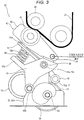
Fig. 3 is a diagram corresponding to a cross section taken along line A-A ofFig. 2 ; -
Fig. 4 is a diagram corresponding to a cross section taken along line B-B ofFig. 2 ; -
Fig. 5 is a perspective view illustrating each part of a secondary transfer unit separately; -
Fig. 6 is a diagram illustrating a main part of the secondary transfer device at the time of separation; -
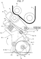
Fig. 7 is a diagram illustrating a main part of the secondary transfer device at the time of pressure bonding; -
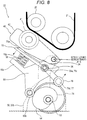
Fig. 8 is a diagram illustrating a main part of the secondary transfer device at the time of depressurization; -
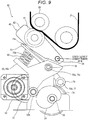
Fig. 9 is an explanatory diagram illustrating how a first drive and a second drive overlap; -
Fig. 10 is a diagram illustrating a secondary transfer device having a configuration in which only one depressurization cam is disposed at the center in the front-rear direction; and -
Figs. 11A and 11B are diagrams illustrating a comparison between a normal state and a state in which a lock mechanism is released and a rotation shaft is moved. - Hereinafter, one or more embodiments of the present invention will be described with reference to the drawings. However, the scope of the invention is not limited to the disclosed embodiments.
-
Fig. 1 illustrates a schematic configuration of animage forming apparatus 10 including a secondary transfer device according to an embodiment of the invention. Theimage forming apparatus 10 has a so-called multifunction machine that includes a copy function of forming an image obtained by optically reading an original document on a recording material such as recording paper and outputting the image, and a print function of forming an image rasterized on the recording paper based on print data input from the outside and outputting the image on the recording paper. The recording material is not limited to recording paper, but may be a film or cloth. Hereinafter, the recording material will be described as recording paper. - The
image forming apparatus 10 includes ascanner portion 11 that optically reads an original document, anoperation panel 12 that receives a user operation and displays various information, acontrol circuit portion 13 that controls the operation of the entire apparatus and performs image processing, animage forming portion 20 that forms an unfixed toner image on a recording material, afixing device 15 that fixes an unfixed toner image to the recording paper, asheet feed tray 14 that is capable of storing a large number of recording paper used for image formation, and a transport portion 16 that transports the sheet fed from thesheet feed tray 14. - The
image forming portion 20 forms a toner image by an electrophotographic method. Theimage forming portion 20 forms an endless annularintermediate transfer belt 21 having a predetermined width and being wound around a plurality of rollers,image forming units secondary transfer device 30 for secondarily transferring the toner image formed in the outer peripheral surface of theintermediate transfer belt 21 onto the recording paper. Further, theimage forming units - The
image forming units image forming units photosensitive drum 24 as an electrostatic latent image carrier on which an electrostatic latent image is formed the surface, and a charging device, a developing device, a transfer device, a photosensitive drum cleaning device, and the like are arranged around the drum Aprint head 26 is provided which includes a laser diode (LD) as a laser element, a polygon mirror, various lenses, a mirror, and the like. - In each of the
image forming units photosensitive drum 24 is driven by a drive unit, which is not illustrated, to rotate in a certain direction, and the charging device uniformly charges thephotosensitive drum 24, and theprint head 26 scans thephotosensitive drum 24 with a laser beam controlled to be on/off in accordance with a drive signal based on image data of a corresponding color to form an electrostatic latent image on the surface of thephotosensitive drum 24. - The developing device performs a developing step of developing the electrostatic latent image on the surface of the
photosensitive drum 24 with toner. The toner image formed on the surface of thephotosensitive drum 24 is transferred (primary-transferred) to theintermediate transfer belt 21 at a portion where the toner image contacts theintermediate transfer belt 21. The photosensitive drum cleaning device removes and collects the toner remaining on the surface of thephotosensitive drum 24 by rubbing with a blade or the like after the transfer. - The
intermediate transfer belt 21 wound around the plurality of rollers is driven by a drive unit, which is not illustrated, and rotates in the direction of arrow A in the drawing. In the course of the rotation, the toner images formed on thephotosensitive drums 24 of theimage forming units intermediate transfer belt 21 and are superimposed to form a full-color image. The images are synthesized on theintermediate transfer belt 21. This toner image is transferred (secondary transfer) from theintermediate transfer belt 21 onto the recording paper by thesecondary transfer device 30 arranged at the secondary transfer position D. Further, the toner remaining on theintermediate transfer belt 21 after the secondary transfer is removed from theintermediate transfer belt 21 by acleaning device 27 provided downstream of the secondary transfer position D. - The
fixing device 15 is provided in the middle of a transport path of the recording paper and downstream of the secondary transfer position D, and presses, heats, and fixes the toner image, which is transferred onto the surface of the recording paper at the secondary transfer position D, to the recording paper. - The transport portion 16 has a function of transporting the recording paper fed from the
sheet feed tray 14 to adischarge tray 17 through the secondary transfer position D and thefixing device 15. The transport portion 16 includes a motor that drives the transport roller besides a transport roller and a guide that form a transport path. Although not illustrated, the transport portion 16 includes a sheet reversing mechanism for double-sided printing that reverses the recording paper exiting thefixing device 15 and sends the recording paper again to the transport path upstream of the secondary transfer position D. - The
control circuit portion 13 includes a CPU (Central Processing Unit), a ROM (Read Only Memory), a RAM (Random Access Memory), and the like as main components. Each function as theimage forming apparatus 10 is realized by the CPU executing the processing according to the program stored in the ROM. Thecontrol circuit portion 13 controls operations of the transport portion 16, theimage forming portion 20, thesecondary transfer device 30, and the like. -
Fig. 2 is a left side view of the secondary transfer device 30 (a view of thesecondary transfer device 30 viewed from the fixingdevice 15 side inFig. 1 ), andFig. 3 is a diagram corresponding to a cross section taken along line A-A inFig. 2 , andFig. 4 is a view corresponding to the cross section taken along line B-B ofFig. 2 .Fig. 5 is an exploded perspective view of thesecondary transfer device 30.Figs. 6 to 8 are diagrams illustrating the outline of the operation of a main part of the mechanical configuration of thesecondary transfer device 30 extracted. - The
secondary transfer device 30 presses asecondary transfer roller 41, having the width direction of theintermediate transfer belt 21 as the axial direction, against the outer peripheral surface of theintermediate transfer belt 21 at the secondary transfer position D, so that a transfer nip is formed by interposing theintermediate transfer belt 21 between thesecondary transfer roller 41 and a roller (an opposite roller 28) disposed at a position facing thesecondary transfer roller 41 in the plurality of rollers around which theintermediate transfer belt 21 is wound. Hereinafter, the width direction of the intermediate transfer belt 21 (the axial direction of the secondary transfer roller 41) is referred to as "front-rear direction". Further, a relative position on the end side in the front-rear direction is called "outside", and a relative position closer to the center in the front-rear direction is "inside". - The
secondary transfer roller 41 is incorporated in thesecondary transfer unit 40, as illustrated inFigs. 3 and5 . Thesecondary transfer unit 40 is configured by rotatably supporting thesecondary transfer roller 41 on aframe member 42 and mounting aguide plate 43 and the like for guiding a sheet to the transfer nip to theframe member 42. - The
secondary transfer device 30 is configured by mounting, to theframe member 32, the above-describedsecondary transfer unit 40, a pressure-releasing portion (pressure-releasing mechanism) 50 for displacing thesecondary transfer unit 40 so as to be displaced to a pressing position at which thesecondary transfer roller 41 is pressed against theintermediate transfer belt 21 to form a transfer nip, and a separated position at which thesecondary transfer roller 41 is separated from theintermediate transfer belt 21, afirst drive 52 including a motor and gears for driving the pressure-releasingportion 50, a high-speed depressurization portion (high-speed depressurization mechanism) 70 that temporarily decompresses the nip pressure, with which thesecondary transfer roller 41 at the pressing position presses theintermediate transfer belt 21 interposed with theopposite roller 28, when the leading end and the tailing end of the sheet pass the secondary transfer location D (between thesecondary transfer roller 41 and the intermediate transfer belt 21), and asecond drive 72 including a motor and the like that drives the high-speed depressurization portion 70 (SeeFig. 5 ). - As illustrated in
Figs. 2 and5 , theframe member 32 includes a rectangular plate-shapedbottom plate part 32a which is long in the front-rear direction of thesecondary transfer device 30 and a pair ofsupport plates 32b which erect from the vicinity of both ends in the front-rear direction of thebottom plate part 32a toward each other. Each of the opposingsupport plates 32b has its lower portion screwed to thebottom plate part 32a, and its upper portion is narrower than the lower portion. In the vicinity of the upper end of eachsupport plate 32b, aunit support shaft 34 of a predetermined length for swingably supporting thesecondary transfer unit 40 is provided so as to protrude outward in the front-rear direction. - The
secondary transfer unit 40 is pivotally supported at both ends in the front-rear direction by theunit support shaft 34, and swings around theunit support shaft 34, so that thesecondary transfer roller 41 having an axial center at a distance separated from theunit support shaft 34 to the downstream side in the sheet transport direction is displaced to a pressing position and a separating position. - The pressure-releasing
portion 50 includes apressing cam 54 which is supported by arotation shaft 53 driven by afirst drive 52 in the same direction as the axis of thesecondary transfer roller 41 and rotates, and apressing arm 55 that abuts on thepressing cam 54 and oscillates to displace thesecondary transfer unit 40 between the pressing position and the separated position. Thepressing cam 54 and thepressing arm 55 are provided at both ends in the front-rear direction corresponding to therespective support plates 32b. - The
pressing arm 55 is configured such that arotation fulcrum 55a at one end thereof is pivotally supported by a support shaft 36 (seeFigs. 2 ,3 , and5 ) mounted to thesupport plate 32b slightly below theunit support shaft 34. The axial direction of thesupport shaft 36 that supports therotation fulcrum 55a of thepressing arm 55 is the same as the axis of thesecondary transfer roller 41. - As illustrated in
Figs. 3 ,6 and the like, therotation shaft 53 is rotatably supported by thesupport plate 32b at a position shifted slightly below therotation fulcrum 55a of thepressing arm 55 to the upstream side in the sheet transport direction. - The
pressing arm 55 has the above-describedrotation fulcrum 55a at one end (upper end), and has acontact roller 55b (abutting member) at the other end (lower end) which comes into contact with thepressing cam 54 and becomes a force point, and a workingarm 55c which protrudes sideways (upstream side in the sheet transport direction) on the way (seeFigs. 3 and6 ). - A
spring 56 extending upward spirally is mounted to the upper surface near the tip of the workingarm 55c of thepressing arm 55, and the upper end of thespring 56 is bonded to the lower surface of the tip of adepressurization arm 75 described later. Thepressing arm 55 has a working point where thespring 56 near the tip of the workingarm 55c is mounted, and when the transfer nip is formed, the back surface of thesecondary transfer unit 40 is pressed toward theopposite roller 28 via thespring 56 and thedepressurization arm 75. - The pressure-releasing
portion 50 includes twopressing cams 54 arranged at both ends in the axial direction (front-rear direction) of thesecondary transfer roller 41 in the same phase, and by using the respectivepressing arms 55 at both ends, the back surface of thesecondary transfer unit 40 is simultaneously and similarly pressed at both ends in the front-rear direction, and the pressing is released. - The high-
speed depressurization portion 70 includes adepressurization cam 74 which is mounted to arotation shaft 73 driven by thesecond drive 72 and rotates in the same direction as thesecondary transfer roller 41, and adepressurization arm 75 which abuts on thedepressurization cam 74 and swings to displace thesecondary transfer unit 40 at the pressing position in a direction where the nip pressure decreases. Therotation shaft 73 has a cylindrical shape, is fitted around therotation shaft 53 of the pressure-releasingportion 50, and is coaxial with therotation shaft 53. - The
depressurization cam 74 includes aslope 74a and aflat part 74b as a region of the outer periphery where a depressurization state where the nip pressure decreases (seeFig. 7 ). In the control of the high-speed depressurization portion 70, these regions are properly used according to the length of time for maintaining the depressurization. - The
depressurization cam 74 and thepressing cam 54 aligned coaxially are in a positional relationship in which the projected images projected in the axial direction of thesecondary transfer roller 41 are maximally overlapped. Further, the maximum diameter of thepressing cam 54 is smaller than the minimum diameter of thedepressurization cam 74. - As illustrated in
Figs. 2 ,5 and the like, thedepressurization arms 75 are provided corresponding to the twopressing arms 55 at both ends in the front-rear direction. One end of thedepressurization arm 75 is apressing portion 75a that presses the back surface of thesecondary transfer unit 40 toward the intermediate transfer belt 21 (seeFig. 3 and the like), and the back surface of thepressing portion 75a abuts on the upper end of thespring 56. The position where the upper end of thespring 56 is in contact is the workingpoint 75b of thedepressurization arm 75 in the depressurization operation. - The other end of the
depressurization arm 75 is aforce point 75d which receives a force from thedepressurization cam 74. Here, theforce points 75d at the ends of the twodepressurization arms 75 provided separately at both ends in the front-rear direction corresponding to thepressing arms 55 are connected by a depressurization shaft 77 (connecting member) that is long in the front-rear direction. A cylindricalrotating body 78 that is long in the front-rear direction and freely rotates around thedepressurization shaft 77 is fitted around thedepressurization shaft 77. - When the
rotating body 78 comes into contact with thedepressurization cam 74, thedepressurization arm 75 swings. By using the rotatingbody 78 as a member that abuts on thedepressurization cam 74, friction with thedepressurization cam 74 is reduced, and the durability of thedepressurization cam 74 is improved. Further, a configuration in which thedepressurization shaft 77 abuts on thedepressurization cam 74 without providing therotating body 78 may be employed. - A
rotation fulcrum 75c of thedepressurization arm 75 is located slightly closer to the end, where thedepressurization shaft 77 is connected, from the center of thedepressurization arm 75 in the longitudinal direction. Therotation fulcrum 75c is supported by thesupport plate 32b so as to be coaxial with therotation fulcrum 55a of thepressing arm 55. In thedepressurization arm 75, the distance from therotation fulcrum 75c to theworking point 75b (a portion where thespring 56 abuts on the back surface) at the time of depressurization is longer than the distance between theforce point 75d (where thedepressurization shaft 77 is connected) receiving the force from thedepressurization cam 74 and therotation fulcrum 75c. Thus, downsizing, and downsizing and cost reduction of thesecond drive 72 can be achieved. - In addition, the force point of the depressurization arm 75 (the rotating
body 78 of the depressurization shaft 77), that is, a portion that comes into contact with thedepressurization cam 74, is located between therotation fulcrum 55a of thepressing arm 55 and thepressing cam 54. Accordingly, the main part of the high-speed depressurization mechanism 70 is disposed so as to be included in the pressure-releasingportion 50, and the apparatus is downsized. - As illustrated in
Fig. 2 , thedepressurization cams 74 are respectively disposed so as to be near the inner sides of the twopressing cams 54 that are separately disposed at both ends in the front-rear direction. Further, a second drive 72 (a motor or the like) for rotating therotation shaft 73 of thedepressurization cam 74 and aposition detection sensor 76 for detecting the angular position of thedepressurization cam 74 are disposed inside the twodepressurization cams 74. - A first drive 52 (a motor or the like) for rotating the
rotation shaft 53, to which thepressing cam 54 is mounted, is mounted to one end of thesecondary transfer device 30 in the front-rear direction. Specifically, it is mounted at a position outside thepressing cam 54 and thepressing arm 55. - Further, as illustrated in
Fig. 9 , thefirst drive 52 and thesecond drive 72 are disposed so that the projected images when projected in the axial direction of thesecondary transfer roller 41 overlap. - Further, in the
image forming apparatus 10, the pressure-releasingportion 50 and the high-speed depressurization mechanism 70 of thesecondary transfer device 30 are disposed on the opposite side of theintermediate transfer belt 21 with respect to the secondary transfer position D. As illustrated inFigs. 1 ,3 and the like, the secondary transfer device 30 (the pressure-releasingportion 50, the high-speed depressurization mechanism 70) is located below the secondary transfer position D. Theintermediate transfer belt 21 is located above the secondary transfer position D. The pressure-releasingportion 50 and the high-speed depressurization mechanism 70 are located on the opposite side of theintermediate transfer belt 21 with respect to the secondary transfer position D. - Next, the operation of the
secondary transfer device 30 will be described. -
Fig. 6 illustrates a state in which thesecondary transfer unit 40 is at the separated position.Fig. 7 illustrates a state in which thesecondary transfer unit 40 is at the pressing position (pressure bonding state).Fig. 8 illustrates a state where the high-speed depressurization portion 70 operates to reduce the nip pressure. - When the
secondary transfer device 30 rotates therotation shaft 53 of the pressure-releasingportion 50 by thefirst drive 52, thepressing cam 54 mounted to therotation shaft 53 rotates. Thepressing arm 55 in which thecontact roller 55b of the lower end abuts on thepressing cam 54 swings about therotation fulcrum 55a in accordance with the angular position of thepressing cam 54. - When the
secondary transfer unit 40 is displaced from the separation position to the pressing position, thepressing arm 55 rotates rightward (clockwise) from the position illustrated inFig. 6 , and presses thesecondary transfer unit 40 toward theintermediate transfer belt 21 at the working point near the tip of the workingarm 55c via thespring 56 and thedepressurization arm 75 in this order.Fig. 7 illustrates a state in which depressurization by the high-speed depressurization portion 70 is not applied, and thedepressurization cam 74 is at an angular position where it does not come into contact with the force point of the depressurization arm 75 (the rotatingbody 78 of the depressurization shaft 77). Accordingly, in this state, thedepressurization arm 75 does not receive a force from thedepressurization cam 74, and is displaced in accordance with the pressing operation of the pressure-releasingportion 50. - When the
depressurization cam 74 of the high-speed depressurization portion 70 is rotated to a predetermined angular position while holding thepressing cam 54 of the pressure-releasingportion 50 at the position illustrated inFig. 7 , thedepressurization cam 74 abuts on the force point (the rotatingbody 78 of the depressurization shaft 77) of thedepressurization arm 75 and thedepressurization arm 75 slightly rotates therotation fulcrum 75c toward the center in the counterclockwise direction, and thepressing arm 55 is pushed back via thespring 56 at the workingpoint 75b in the end opposite to theforce point 75d with the rotation fulcrum interposed as illustrated inFig. 8 . - That is, the
depressurization arm 75 reduces the nip pressure by blocking the pressing force exerted on thesecondary transfer unit 40 by thepressing arm 55 via thespring 56. At this time, the axial distance between theopposite roller 28 and thesecondary transfer roller 41 is somewhat shorter than the sum of the radius of theopposite roller 28 and the radius of thesecondary transfer roller 41 when not in contact, and the nip pressure is generated by the elasticity of the outer peripheral members of thesecondary transfer roller 41 and theopposite roller 28. - As described above, the
secondary transfer device 30 according to the invention temporarily forms the depressurization state by the high-speed depressurization portion 70, which is a mechanism different from the pressure-releasingportion 50 that displaces thesecondary transfer unit 40 to the pressing position. Therefore, a temporary depressurization state can be easily and smoothly formed at an appropriate timing. - That is, the pressurization operation is performed by the
pressing arm 55 pressing thesecondary transfer unit 40 via thespring 56 and thedepressurization arm 75, and the depressurization operation is performed by displace thedepressurization arm 75 such that thespring 56 pushes back toward thepressing arm 55. Therefore, a suitable degree of depressurization can be easily obtained compared to a mechanism in which the pressure-releasingportion 50 slightly displaces thepressing arm 55 toward the separation position to reduce the pressure. In addition, since the operation stroke of thedepressurization arm 75 in the depressurization operation can be small, the depressurization operation and the depressurization release operation can be performed at high speed. - The
control circuit portion 13 controls thesecond drive 72 of the high-speed depressurization portion 70 so that the pressure (nip pressure) is temporarily reduced when the leading edge and the trailing edge of the sheet pass the secondary transfer position D. Specifically, a sensor for detecting the leading and trailing ends of the sheet is provided slightly upstream in the sheet transport direction of the secondary transfer position D, and the angular position of thedepressurization cam 74 is controlled by thesecond drive 72 to be the depressurization state only in a predetermined period before and after the leading and tailing ends of the sheet pass the secondary transfer position D with reference to the timing when the sensor detects the leading and tailing ends of the sheet. - The
depressurization cam 74 is provided with theslope 74a and theflat part 74b on the outer circumference as a region where a depressurization state is formed. In the control of the high-speed depressurization portion 70, thecontrol circuit portion 13 properly uses these regions according to a time for maintaining the depressurization. - More specifically, when maintaining the depressurization state for a certain period of time or more, the
control circuit portion 13 sets the angular position of thedepressurization cam 74 so that theflat part 74b of thedepressurization cam 74 abuts on the force point (the rotatingbody 78 of the depressurization shaft 77) of thedepressurization arm 75 to form the depressurization state, and stops thesecond drive 72 at the position to maintain the depressurization state. - On the other hand, if the time for maintaining the depressurization state is a short time less than a fixed time, the
control circuit portion 13 forms the depressurization state using theslope 74a of thedepressurization cam 74 where the force point of the depressurization arm 75 (the rotatingbody 78 of the depressurization shaft 77) abuts. Specifically, while thesecond drive 72 is being driven (while thedepressurization cam 74 is being rotated), theslope 74a is continuously formed over an angle range in which the depressurization state occurs for a required time, and thecontrol circuit portion 13 forms the depressurization state for the required time while driving thesecond drive 72 and maintaining the rotation of thedepressurization cam 74. - For example, as illustrated in
Fig. 7 , when theslopes 74a are provided on both sides of theflat part 74b, the rotatingbody 78 abuts on theslope 74a of thedepressurization cam 74, theflat part 74b, and theslopes 74a sequentially by continuing the rotation of thedepressurization cam 74, and during that time, the depressurization state is continuously formed. If the rotation of thedepressurization cam 74 is temporarily stopped when therotating body 78 comes to the angular position where it abuts from the oneslope 74a to theflat part 74b, the depressurization state can be extended during the temporary stop. - Since the
depressurization cam 74 is provided with theflat part 74b, the depressurization state for a certain time or more can be formed by stopping the excitation of the motor, so that the power consumption can be reduced, and the motor can be reduced in size and power. Further, when the depressurization state is formed for a short time and released, the rotation of thedepressurization cam 74 may be continued, so that the control of thesecond drive 72 is facilitated. - In addition, since the
rotation shaft 53 holding thepressing cam 54 and therotation shaft 73 holding thedepressurization cam 74 are coaxial, the positional accuracy when controlling the angular position of these cams is improved. - The
secondary transfer device 30 is downsized by the following configuration. First, the pressure-releasingportion 50 and the high-speed depressurization portion 70 are disposed so that the projected images when they are projected in the axial direction of thesecondary transfer roller 41 overlap. More specifically, the projection images obtained by projecting thepressing cam 54 and thedepressurization cam 74 in the axial direction of thesecondary transfer roller 41 partially or entirely overlap. As a result, the area of thesecondary transfer device 30 in a cross section perpendicular to the axis of thesecondary transfer roller 41 is reduced. - In the present embodiment, the
rotation shaft 53 of thepressing cam 54 and therotation shaft 73 of thedepressurization cam 74 are coaxial, so that the overlap between these cams is the largest. - In addition, as illustrated in
Fig. 9 , thefirst drive 52 and thesecond drive 72 are also disposed such that the projected images when projected in the axial direction of thesecondary transfer roller 41 overlap, and the area of thesecondary transfer device 30 in the cross section perpendicular to the axis of thesecondary transfer roller 41 is reduced. - In addition, by disposing the pressure-releasing
portion 50 and the high-speed depressurization portion 70 on the opposite side of the intermediate transfer belt with respect to the secondary transfer position, the rotating route of the intermediate transfer belt can be reduced, and the size of the image forming apparatus including the secondary transfer device can be reduced compared to the case where the pressure-releasingportion 50 and the high-speed depressurization portion 70 are provided inside the intermediate transfer belt. Further, by providing the pressure-releasingportion 50 and the high-speed depressurization portion 70 below thesecondary transfer unit 40, the overall size of theimage forming portion 20 including thesecondary transfer device 30 is reduced. - Further, as illustrated in
Fig. 2 , apressing arm 55 and apressing cam 54 are provided at two locations separated at both ends in the front-rear direction (the axial direction of the secondary transfer roller 41), and adepressurization cam 74 is disposed inside these two portions. Therefore, the size of the apparatus in the front-rear direction can be reduced as compared to the case where thedepressurization cam 74 is provided outside thepressing cam 54. In the configuration illustrated inFig. 2 , thedepressurization cams 74 are provided at two locations near the inside of each of thepressing cams 54, separated from each other in the front-rear direction, so that a depressurization force is applied near thedepressurization arm 75 to therotating body 78 of thedepressurization shaft 77, and the deflection of thedepressurization shaft 77 can be reduced. - As illustrated in
Fig. 10 , thedepressurization cam 74 may be configured such that only onedepressurization cam 74 is disposed inside the twopressing cams 54 provided separately at both ends in the front depth direction and at the center in the front-rear direction. When thedepressurization cams 74 are provided at two locations separated in the front-rear direction as illustrated inFig. 2 , there is a possibility that a difference occurs in the depressurization operations due to the shape and phase shift of the cams. In the configuration in which thedepressurization cam 74 is provided only at a position of the center in the front-rear direction, the depressurization operation can be performed by synchronizing thedepressurization arms 75 at both ends without being affected by the above difference. - In addition, as illustrated in
Fig. 2 , when twodepressurization cams 74 are disposed separately at both ends in the front-rear direction, aposition detection sensor 76 that detects the angular position of thesecond drive 72 and thedepressurization cam 74 is disposed inside. Therefore, the size of thesecondary transfer device 30 in the front-rear direction is reduced. In addition, as illustrated inFig. 10 , even in the configuration having onedepressurization cam 74, thesecond drive 72 and theposition detection sensor 76 are disposed inside the twopressing cams 54 divided at both ends in the front-rear direction. The size of thesecondary transfer device 30 in the front-rear direction is reduced. - In addition, the
rotation fulcrum 75c of thedepressurization arm 75 is provided between the force point (a connection location of the depressurization shaft 77) at which thedepressurization arm 75 receives a force from thedepressurization cam 74 and the working point (a location where the tip of thespring 56 abuts) of thedepressurization arm 75. Therefore, the direction in which the working point of thedepressurization arm 75 applies a force to thespring 56 for depressurization and the direction in which the force point of thedepressurization arm 75 is pressed during depressurization are reversed, and the degree of freedom of arrangement is increased. It is possible to select an arrangement that contributes to miniaturization. - Further, since the
secondary transfer roller 41 is incorporated into thesecondary transfer unit 40 to form a unit, the size, the maintainability, and the exchangeability of the high-speed depressurization portion 70 are improved. In addition, since the portion where the force for displacing thesecondary transfer roller 41 is applied can be set at an arbitrary portion or the like of theframe member 42 of thesecondary transfer unit 40, the degree of freedom of arrangement of each part is increased. - Further, the relationship between the
pressing cam 54 and thedepressurization cam 74 is coaxial, and the maximum diameter of thepressing cam 54 is smaller than the minimum diameter of thedepressurization cam 74. Thus, the depressurization operation by thedepressurization cam 74 can be performed irrespective of the position of thepressing cam 54. If the minimum diameter of thepressing cam 54 is larger than the maximum diameter of thedepressurization cam 74, the pressing operation by thepressing cam 54 can be performed regardless of the position of thedepressurization cam 74. - In addition, the
rotation shaft 53 of thepressing cam 54 can be moved in the axial direction when a lock mechanism, which is not illustrated, is released, and thepressing cam 54 and thecontact roller 55b on thepressing arm 55 side are displaced due to the movement.Fig. 11A illustrates a normal use state locked by the lock mechanism, andFig. 11B illustrates a state in which the lock mechanism is released and therotation shaft 53 and therotation shaft 73 coaxial therewith are simultaneously moved to release the above engagement. In the case ofFigs. 11A and 11B , thepressing cam 54 and thecontact roller 55b of thepressing arm 55 are displaced and disengaged from each other, so that thepressing arm 55 is in the separated position as illustrated inFig. 6 . Accordingly, thedepressurization arm 75 is also displaced, and therotating body 78 of thedepressurization shaft 77 and thedepressurization cam 74 are separated from each other, and the engagement is simultaneously released. - For example, when the
secondary transfer device 30 is stopped in the pressing state or the depressurization state due to some trouble, the pressing state or the depressurization state is released by releasing the lock mechanism and moving therotation shafts - Further, also in the high-
speed depressurization portion 70, thedepressurization cam 74 and therotating body 78 of thedepressurization shaft 77 are engaged in the normal use state in which the movement of therotation shaft 73 in the front-rear direction is restricted by the lock mechanism, and the lock mechanism is released. Then, when therotation shaft 73 is moved in the front-rear direction, the rotatingbody 78 of thedepressurization shaft 77 and thedepressurization cam 74 may be displaced and disengaged. For example, the diameter of therotating body 78 may be made larger than other parts only in a portion corresponding to a position corresponding to thedepressurization cam 74 in the normal use state. - The embodiment of the invention has been described with reference to the drawings. However, the specific configuration is not limited to that illustrated in the embodiment, and there are changes and additions within the scope of the invention, which are also included in the invention.
- For example, the
secondary transfer roller 41 may not be incorporated in thesecondary transfer unit 40, and the pressure-releasingportion 50 may press the axis of thesecondary transfer roller 41. - In the embodiment, the
pressing arm 55 presses thesecondary transfer unit 40 via thespring 56 and thedepressurization arm 75, and thedepressurization arm 75 pushes back thespring 56 when the pressure is reduced. For example, thepressing arm 55 may press thesecondary transfer unit 40 via thespring 56, and thedepressurization arm 75 may be engaged with a hook provided at both ends of thesecondary transfer unit 40 to apply a force to thesecondary transfer unit 40 in a direction toward the separation position. The shape of thespring 56 is not limited to the shape illustrated in the embodiment, and may be a leaf spring or the like, or may be an elastic body having necessary elasticity. - A secondary transfer device for secondary-transferring a toner image primary-transferred on an outer peripheral surface of an endless annular intermediate transfer belt to a sheet at a predetermined secondary transfer position, the intermediate transfer belt having a predetermined width and being wound around a plurality of rollers and rotating, the secondary transfer device including,
a pressure-releasing mechanism that displaces a secondary transfer roller to a pressing position where the intermediate transfer belt is interposed and pressed between the secondary transfer roller and an opposite roller that abuts an inner peripheral surface of the intermediate transfer belt at the secondary transfer position, and a separation position separated from the outer peripheral surface of the intermediate transfer belt,
a first drive that drives the pressure-releasing mechanism,
a high-speed depressurization mechanism that temporarily depressurizes a nip pressure, at which the secondary transfer roller at the pressing position interposes and presses the intermediate transfer belt in a gap with respect to the opposite roller, when a leading end and a tailing end of a sheet pass between the secondary transfer roller and the intermediate transfer belt, and
a second drive that drives the high-speed depressurization mechanism,
wherein the pressure-releasing mechanism and the high-speed depressurization mechanism are disposed on an opposite side of the intermediate transfer belt with respect to the secondary transfer position. - The secondary transfer device according to Note 1,
wherein the pressure-releasing mechanism and the high-speed depressurization mechanism are disposed such that projected images when projected in an axial direction of the secondary transfer roller overlap. - The secondary transfer device according to Note 2,
wherein a portion where the depressurization arm abuts on the depressurization cam is provided between a rotation fulcrum of the pressing arm and the pressing cam. - Although embodiments of the present invention have been described and illustrated in detail, the disclosed embodiments are made for purposes of illustration and example only and not limitation. The scope of the present invention should be interpreted by terms of the appended claims.
Claims (15)
- A secondary transfer device (30) for secondary-transferring a toner image primary-transferred on an outer peripheral surface of an endless annular intermediate transfer belt (21) to a sheet at a predetermined secondary transfer position (D), the intermediate transfer belt (21) having a predetermined width and being wound around a plurality of rollers and rotating, the secondary transfer device (30) comprising:a pressure-releasing mechanism (50) that displaces a secondary transfer roller (41) to a pressing position, where the intermediate transfer belt (21) is interposed and pressed between the secondary transfer roller (41) and an opposite roller (28) that abuts an inner peripheral surface of the intermediate transfer belt (21) at the secondary transfer position (D), and a separation position separated from the outer peripheral surface of the intermediate transfer belt (21);a first drive (52) that drives the pressure-releasing mechanism (50);a high-speed depressurization mechanism (70) that temporarily depressurizes a nip pressure, at which the secondary transfer roller (41) at the pressing position interposes and presses the intermediate transfer belt (21) in a gap with respect to the opposite roller (28), when a leading end and a tailing end of a sheet pass between the secondary transfer roller (41) and the intermediate transfer belt (21); anda second drive (72) that drives the high-speed depressurization mechanism (70),wherein the pressure-releasing mechanism (50) and the high-speed depressurization mechanism (70) are arranged such that projected images when projected in an axial direction of the secondary transfer roller (41) overlap.
- The secondary transfer device (30) according to claim 1,wherein the pressure-releasing mechanism (50) includes a pressing cam (54) that is supported to a rotation shaft (53) driven by the first drive (52) in the same direction as an axis of the secondary transfer roller (41), and a pressing arm (55) that abuts on the pressing cam (54) and swings to displace the secondary transfer roller (41) to the pressing position and the separation position,the high-speed depressurization mechanism (70) includes a depressurization cam (74) that is supported to a rotation shaft (73) driven by the second drive (72) in the same direction as an axis of the secondary transfer roller (41), and a depressurization arm (75) that abuts on the depressurization cam (74) and swings to displace the axis of the secondary transfer roller (41) in the pressing position in a direction in which the nip pressure decreases, andthe projected images of the pressing cam (54) and the depressurization cam (74) overlap with each other.
- The secondary transfer device (30) according to claim 2,
wherein the rotation shaft (53) of the pressing cam (54) and the rotation shaft (73) of the depressurization cam (74) are coaxial. - The secondary transfer device (30) according to claim 3,
wherein a maximum diameter of the pressing cam (54) is smaller than a minimum diameter of the depressurization cam (74). - The secondary transfer device (30) according to claim 3,
wherein a minimum diameter of the pressing cam (54) is larger than a maximum diameter of the depressurization cam (74). - The secondary transfer device (30) according to claim 3,
wherein the pressing arm (55) and the pressing cam (54) are provided at two locations separated at both ends in an axial direction of the secondary transfer roller (41), and the depressurization cam (74) is disposed inside these two locations. - The secondary transfer device (30) according to claim 6,wherein the depressurization arms (75) are provided at two locations separated at both ends in the axial direction of the secondary transfer roller (41), and locations of force points (75d) of these depressurization arms (75) are connected to each other by a connecting member,the depressurization cam (74) is disposed at a center in the axial direction of the secondary transfer roller (41), andthe connecting member abuts on the depressurization cam (74), and the depressurization arm (75) swings.
- The secondary transfer device (30) according to claim 6,wherein the depressurization arms (75) are provided at two locations separated at both ends in the axial direction of the secondary transfer roller (41), and locations of force points (75d) of these depressurization arms (75) are connected to each other by a connecting member, and whereinthe depressurization cams (74) are disposed near an inside of the pressing cam (54), respectively, and the connecting member abuts on the depressurization cam (74), and the depressurization arm (75) swings, or whereinthe depressurization cam (74) is disposed near the inside of the pressing cam (54), respectively, and a position detecting means that detects an angular position of the second drive (72) and the depressurization cam (74) is disposed inside the two depressurization cams (74).
- The secondary transfer device (30) according to claim 2 or 3,
wherein the depressurization arm (75) abuts on the depressurization cam (74) with a rotating body (78). - The secondary transfer device (30) according to claim 2 or 3,
wherein a rotation fulcrum (75c) of the depressurization arm (75) is located between a force point (75d) where the depressurization arm (75) receives a force from the depressurization cam (74) and a working point where the depressurization arm (75) applies a force in a direction in which the nip pressure decreases. - The secondary transfer device (30) according to claim 10,
wherein a distance from the rotation fulcrum (75c) to the working point is longer than a distance from the force point (75d) of the depressurization arm (75) to the rotation fulcrum (75c). - The secondary transfer device (30) according to any one of claims 1 to 3,
wherein the first drive (52) and the second drive (72) are disposed so that projected images when projected in an axial direction of the secondary transfer roller (41) overlap. - The secondary transfer device (30) according to claim 2 or 3,wherein the pressing arm (55) pushes the secondary transfer roller (41) toward the pressing position through the spring (56) and the depressurization arm (75) in this order, andthe high-speed depressurization mechanism (70) performs the depressurization by pushing the spring (56) back to the pressing arm (55) side with the depressurization arm (75).
- The secondary transfer device (30) according to claim 2 or 3,wherein the depressurization cam (74) includes a slope (74a) and a flat part (74b) on an outer periphery, as a region where a depressurization state is formed, andthe slope (74a) and the flat part (74b) are properly used depending on a length of time to maintain depressurization.
- The secondary transfer device (30) according to any one of claims 1 to 14,wherein the secondary transfer roller (41) is provided in a secondary transfer unit (40), andthe pressure-releasing mechanism (50) and the high-speed depressurization mechanism (70) displace the secondary transfer unit (40), andwherein the pressure-releasing mechanism (50) and the high-speed depressurization mechanism (70) are provided below the secondary transfer unit (40).
Applications Claiming Priority (2)
| Application Number | Priority Date | Filing Date | Title |
|---|---|---|---|
| JP2019087308A JP7311833B2 (en) | 2019-05-07 | 2019-05-07 | Secondary transfer device |
| JP2019087307A JP7240601B2 (en) | 2019-05-07 | 2019-05-07 | Secondary transfer device |
Publications (2)
| Publication Number | Publication Date |
|---|---|
| EP3736636A1 true EP3736636A1 (en) | 2020-11-11 |
| EP3736636B1 EP3736636B1 (en) | 2022-10-26 |
Family
ID=70482267
Family Applications (1)
| Application Number | Title | Priority Date | Filing Date |
|---|---|---|---|
| EP20172217.0A Active EP3736636B1 (en) | 2019-05-07 | 2020-04-29 | Secondary transfer device |
Country Status (2)
| Country | Link |
|---|---|
| US (1) | US20200356021A1 (en) |
| EP (1) | EP3736636B1 (en) |
Citations (4)
| Publication number | Priority date | Publication date | Assignee | Title |
|---|---|---|---|---|
| JP2010134125A (en) * | 2008-12-03 | 2010-06-17 | Ricoh Co Ltd | Image forming apparatus |
| US20100221029A1 (en) * | 2009-03-02 | 2010-09-02 | Minbu Ryuichi | Image forming apparatus |
| JP2017083503A (en) | 2015-10-23 | 2017-05-18 | コニカミノルタ株式会社 | Pressurization driving mechanism and image forming device |
| JP2018031999A (en) * | 2016-08-26 | 2018-03-01 | 株式会社リコー | Pressure application device, transfer device, and image forming apparatus |
-
2020
- 2020-04-15 US US16/849,423 patent/US20200356021A1/en not_active Abandoned
- 2020-04-29 EP EP20172217.0A patent/EP3736636B1/en active Active
Patent Citations (5)
| Publication number | Priority date | Publication date | Assignee | Title |
|---|---|---|---|---|
| JP2010134125A (en) * | 2008-12-03 | 2010-06-17 | Ricoh Co Ltd | Image forming apparatus |
| US20100221029A1 (en) * | 2009-03-02 | 2010-09-02 | Minbu Ryuichi | Image forming apparatus |
| JP2010204259A (en) | 2009-03-02 | 2010-09-16 | Ricoh Co Ltd | Image forming apparatus |
| JP2017083503A (en) | 2015-10-23 | 2017-05-18 | コニカミノルタ株式会社 | Pressurization driving mechanism and image forming device |
| JP2018031999A (en) * | 2016-08-26 | 2018-03-01 | 株式会社リコー | Pressure application device, transfer device, and image forming apparatus |
Also Published As
| Publication number | Publication date |
|---|---|
| US20200356021A1 (en) | 2020-11-12 |
| EP3736636B1 (en) | 2022-10-26 |
Similar Documents
| Publication | Publication Date | Title |
|---|---|---|
| US9229411B2 (en) | Sheet curl correction apparatus and image forming apparatus | |
| US9395654B2 (en) | Image forming apparatus having simple and compact configuration to separate secondary transfer member from primary transfer belt | |
| US20080101812A1 (en) | Image forming apparatus | |
| US7159862B2 (en) | Sheet delivery mechanism for image forming apparatus | |
| JP6425053B2 (en) | Fixing device and image forming apparatus | |
| JP2017227937A5 (en) | ||
| JP2012208171A (en) | Image forming device | |
| JP6222489B2 (en) | Fixing apparatus and image forming apparatus | |
| EP3736636A1 (en) | Secondary transfer device | |
| JP7311835B2 (en) | Secondary transfer device | |
| US10377592B2 (en) | Sheet loading apparatus and image forming apparatus | |
| US9885988B2 (en) | Sheet conveying apparatus and image forming apparatus including same | |
| US20220041389A1 (en) | Sheet feeding device | |
| JP7240601B2 (en) | Secondary transfer device | |
| JP7311833B2 (en) | Secondary transfer device | |
| JP2002351283A (en) | Image forming device | |
| JP6061190B2 (en) | Belt misalignment correction mechanism, belt device, transfer belt device, and image forming apparatus | |
| JP2020201294A (en) | Secondary transfer device and image forming apparatus | |
| JP7484142B2 (en) | Secondary transfer device and image forming apparatus | |
| JP7310515B2 (en) | Secondary transfer device and image forming device | |
| JP2021085917A (en) | Secondary transfer device and image forming apparatus | |
| JP2009116345A (en) | Image forming apparatus | |
| JP2009069649A (en) | Image forming apparatus | |
| JP6590168B2 (en) | Eccentric cam | |
| JPH1179458A (en) | Endless belt feeding device |
Legal Events
| Date | Code | Title | Description |
|---|---|---|---|
| PUAI | Public reference made under article 153(3) epc to a published international application that has entered the european phase |
Free format text: ORIGINAL CODE: 0009012 |
|
| STAA | Information on the status of an ep patent application or granted ep patent |
Free format text: STATUS: THE APPLICATION HAS BEEN PUBLISHED |
|
| AK | Designated contracting states |
Kind code of ref document: A1 Designated state(s): AL AT BE BG CH CY CZ DE DK EE ES FI FR GB GR HR HU IE IS IT LI LT LU LV MC MK MT NL NO PL PT RO RS SE SI SK SM TR |
|
| AX | Request for extension of the european patent |
Extension state: BA ME |
|
| STAA | Information on the status of an ep patent application or granted ep patent |
Free format text: STATUS: REQUEST FOR EXAMINATION WAS MADE |
|
| 17P | Request for examination filed |
Effective date: 20210430 |
|
| RBV | Designated contracting states (corrected) |
Designated state(s): AL AT BE BG CH CY CZ DE DK EE ES FI FR GB GR HR HU IE IS IT LI LT LU LV MC MK MT NL NO PL PT RO RS SE SI SK SM TR |
|
| GRAP | Despatch of communication of intention to grant a patent |
Free format text: ORIGINAL CODE: EPIDOSNIGR1 |
|
| STAA | Information on the status of an ep patent application or granted ep patent |
Free format text: STATUS: GRANT OF PATENT IS INTENDED |
|
| RIC1 | Information provided on ipc code assigned before grant |
Ipc: G03G 15/16 20060101AFI20220421BHEP |
|
| INTG | Intention to grant announced |
Effective date: 20220517 |
|
| GRAS | Grant fee paid |
Free format text: ORIGINAL CODE: EPIDOSNIGR3 |
|
| GRAA | (expected) grant |
Free format text: ORIGINAL CODE: 0009210 |
|
| STAA | Information on the status of an ep patent application or granted ep patent |
Free format text: STATUS: THE PATENT HAS BEEN GRANTED |
|
| AK | Designated contracting states |
Kind code of ref document: B1 Designated state(s): AL AT BE BG CH CY CZ DE DK EE ES FI FR GB GR HR HU IE IS IT LI LT LU LV MC MK MT NL NO PL PT RO RS SE SI SK SM TR |
|
| REG | Reference to a national code |
Ref country code: GB Ref legal event code: FG4D |
|
| REG | Reference to a national code |
Ref country code: CH Ref legal event code: EP |
|
| REG | Reference to a national code |
Ref country code: DE Ref legal event code: R096 Ref document number: 602020005812 Country of ref document: DE |
|
| REG | Reference to a national code |
Ref country code: AT Ref legal event code: REF Ref document number: 1527463 Country of ref document: AT Kind code of ref document: T Effective date: 20221115 |
|
| REG | Reference to a national code |
Ref country code: IE Ref legal event code: FG4D |
|
| REG | Reference to a national code |
Ref country code: LT Ref legal event code: MG9D |
|
| REG | Reference to a national code |
Ref country code: NL Ref legal event code: MP Effective date: 20221026 |
|
| REG | Reference to a national code |
Ref country code: AT Ref legal event code: MK05 Ref document number: 1527463 Country of ref document: AT Kind code of ref document: T Effective date: 20221026 |
|
| PG25 | Lapsed in a contracting state [announced via postgrant information from national office to epo] |
Ref country code: NL Free format text: LAPSE BECAUSE OF FAILURE TO SUBMIT A TRANSLATION OF THE DESCRIPTION OR TO PAY THE FEE WITHIN THE PRESCRIBED TIME-LIMIT Effective date: 20221026 |
|
| PG25 | Lapsed in a contracting state [announced via postgrant information from national office to epo] |
Ref country code: SE Free format text: LAPSE BECAUSE OF FAILURE TO SUBMIT A TRANSLATION OF THE DESCRIPTION OR TO PAY THE FEE WITHIN THE PRESCRIBED TIME-LIMIT Effective date: 20221026 Ref country code: PT Free format text: LAPSE BECAUSE OF FAILURE TO SUBMIT A TRANSLATION OF THE DESCRIPTION OR TO PAY THE FEE WITHIN THE PRESCRIBED TIME-LIMIT Effective date: 20230227 Ref country code: NO Free format text: LAPSE BECAUSE OF FAILURE TO SUBMIT A TRANSLATION OF THE DESCRIPTION OR TO PAY THE FEE WITHIN THE PRESCRIBED TIME-LIMIT Effective date: 20230126 Ref country code: LT Free format text: LAPSE BECAUSE OF FAILURE TO SUBMIT A TRANSLATION OF THE DESCRIPTION OR TO PAY THE FEE WITHIN THE PRESCRIBED TIME-LIMIT Effective date: 20221026 Ref country code: FI Free format text: LAPSE BECAUSE OF FAILURE TO SUBMIT A TRANSLATION OF THE DESCRIPTION OR TO PAY THE FEE WITHIN THE PRESCRIBED TIME-LIMIT Effective date: 20221026 Ref country code: ES Free format text: LAPSE BECAUSE OF FAILURE TO SUBMIT A TRANSLATION OF THE DESCRIPTION OR TO PAY THE FEE WITHIN THE PRESCRIBED TIME-LIMIT Effective date: 20221026 Ref country code: AT Free format text: LAPSE BECAUSE OF FAILURE TO SUBMIT A TRANSLATION OF THE DESCRIPTION OR TO PAY THE FEE WITHIN THE PRESCRIBED TIME-LIMIT Effective date: 20221026 |
|
| PGFP | Annual fee paid to national office [announced via postgrant information from national office to epo] |
Ref country code: FR Payment date: 20230309 Year of fee payment: 4 |
|
| PG25 | Lapsed in a contracting state [announced via postgrant information from national office to epo] |
Ref country code: RS Free format text: LAPSE BECAUSE OF FAILURE TO SUBMIT A TRANSLATION OF THE DESCRIPTION OR TO PAY THE FEE WITHIN THE PRESCRIBED TIME-LIMIT Effective date: 20221026 Ref country code: PL Free format text: LAPSE BECAUSE OF FAILURE TO SUBMIT A TRANSLATION OF THE DESCRIPTION OR TO PAY THE FEE WITHIN THE PRESCRIBED TIME-LIMIT Effective date: 20221026 Ref country code: LV Free format text: LAPSE BECAUSE OF FAILURE TO SUBMIT A TRANSLATION OF THE DESCRIPTION OR TO PAY THE FEE WITHIN THE PRESCRIBED TIME-LIMIT Effective date: 20221026 Ref country code: IS Free format text: LAPSE BECAUSE OF FAILURE TO SUBMIT A TRANSLATION OF THE DESCRIPTION OR TO PAY THE FEE WITHIN THE PRESCRIBED TIME-LIMIT Effective date: 20230226 Ref country code: HR Free format text: LAPSE BECAUSE OF FAILURE TO SUBMIT A TRANSLATION OF THE DESCRIPTION OR TO PAY THE FEE WITHIN THE PRESCRIBED TIME-LIMIT Effective date: 20221026 Ref country code: GR Free format text: LAPSE BECAUSE OF FAILURE TO SUBMIT A TRANSLATION OF THE DESCRIPTION OR TO PAY THE FEE WITHIN THE PRESCRIBED TIME-LIMIT Effective date: 20230127 |
|
| P01 | Opt-out of the competence of the unified patent court (upc) registered |
Effective date: 20230510 |
|
| REG | Reference to a national code |
Ref country code: DE Ref legal event code: R097 Ref document number: 602020005812 Country of ref document: DE |
|
| PG25 | Lapsed in a contracting state [announced via postgrant information from national office to epo] |
Ref country code: SM Free format text: LAPSE BECAUSE OF FAILURE TO SUBMIT A TRANSLATION OF THE DESCRIPTION OR TO PAY THE FEE WITHIN THE PRESCRIBED TIME-LIMIT Effective date: 20221026 Ref country code: RO Free format text: LAPSE BECAUSE OF FAILURE TO SUBMIT A TRANSLATION OF THE DESCRIPTION OR TO PAY THE FEE WITHIN THE PRESCRIBED TIME-LIMIT Effective date: 20221026 Ref country code: EE Free format text: LAPSE BECAUSE OF FAILURE TO SUBMIT A TRANSLATION OF THE DESCRIPTION OR TO PAY THE FEE WITHIN THE PRESCRIBED TIME-LIMIT Effective date: 20221026 Ref country code: DK Free format text: LAPSE BECAUSE OF FAILURE TO SUBMIT A TRANSLATION OF THE DESCRIPTION OR TO PAY THE FEE WITHIN THE PRESCRIBED TIME-LIMIT Effective date: 20221026 Ref country code: CZ Free format text: LAPSE BECAUSE OF FAILURE TO SUBMIT A TRANSLATION OF THE DESCRIPTION OR TO PAY THE FEE WITHIN THE PRESCRIBED TIME-LIMIT Effective date: 20221026 |
|
| PGFP | Annual fee paid to national office [announced via postgrant information from national office to epo] |
Ref country code: DE Payment date: 20230307 Year of fee payment: 4 |
|
| PG25 | Lapsed in a contracting state [announced via postgrant information from national office to epo] |
Ref country code: SK Free format text: LAPSE BECAUSE OF FAILURE TO SUBMIT A TRANSLATION OF THE DESCRIPTION OR TO PAY THE FEE WITHIN THE PRESCRIBED TIME-LIMIT Effective date: 20221026 Ref country code: AL Free format text: LAPSE BECAUSE OF FAILURE TO SUBMIT A TRANSLATION OF THE DESCRIPTION OR TO PAY THE FEE WITHIN THE PRESCRIBED TIME-LIMIT Effective date: 20221026 |
|
| PLBE | No opposition filed within time limit |
Free format text: ORIGINAL CODE: 0009261 |
|
| STAA | Information on the status of an ep patent application or granted ep patent |
Free format text: STATUS: NO OPPOSITION FILED WITHIN TIME LIMIT |
|
| 26N | No opposition filed |
Effective date: 20230727 |
|
| PG25 | Lapsed in a contracting state [announced via postgrant information from national office to epo] |
Ref country code: SI Free format text: LAPSE BECAUSE OF FAILURE TO SUBMIT A TRANSLATION OF THE DESCRIPTION OR TO PAY THE FEE WITHIN THE PRESCRIBED TIME-LIMIT Effective date: 20221026 |
|
| REG | Reference to a national code |
Ref country code: CH Ref legal event code: PL |
|
| PG25 | Lapsed in a contracting state [announced via postgrant information from national office to epo] |
Ref country code: LU Free format text: LAPSE BECAUSE OF NON-PAYMENT OF DUE FEES Effective date: 20230429 |
|
| REG | Reference to a national code |
Ref country code: BE Ref legal event code: MM Effective date: 20230430 |
|
| PG25 | Lapsed in a contracting state [announced via postgrant information from national office to epo] |
Ref country code: MC Free format text: LAPSE BECAUSE OF FAILURE TO SUBMIT A TRANSLATION OF THE DESCRIPTION OR TO PAY THE FEE WITHIN THE PRESCRIBED TIME-LIMIT Effective date: 20221026 |
|
| PG25 | Lapsed in a contracting state [announced via postgrant information from national office to epo] |
Ref country code: MC Free format text: LAPSE BECAUSE OF FAILURE TO SUBMIT A TRANSLATION OF THE DESCRIPTION OR TO PAY THE FEE WITHIN THE PRESCRIBED TIME-LIMIT Effective date: 20221026 Ref country code: LI Free format text: LAPSE BECAUSE OF NON-PAYMENT OF DUE FEES Effective date: 20230430 Ref country code: CH Free format text: LAPSE BECAUSE OF NON-PAYMENT OF DUE FEES Effective date: 20230430 |
|
| REG | Reference to a national code |
Ref country code: IE Ref legal event code: MM4A |
|
| PG25 | Lapsed in a contracting state [announced via postgrant information from national office to epo] |
Ref country code: BE Free format text: LAPSE BECAUSE OF NON-PAYMENT OF DUE FEES Effective date: 20230430 |
|
| PG25 | Lapsed in a contracting state [announced via postgrant information from national office to epo] |
Ref country code: IE Free format text: LAPSE BECAUSE OF NON-PAYMENT OF DUE FEES Effective date: 20230429 |
|
| PG25 | Lapsed in a contracting state [announced via postgrant information from national office to epo] |
Ref country code: IE Free format text: LAPSE BECAUSE OF NON-PAYMENT OF DUE FEES Effective date: 20230429 |
|
| PGFP | Annual fee paid to national office [announced via postgrant information from national office to epo] |
Ref country code: GB Payment date: 20240307 Year of fee payment: 5 Ref country code: GB Payment date: 20240307 Year of fee payment: 4 |